
JerryTodd
-
Posts
879 -
Joined
-
Last visited
Content Type
Profiles
Forums
Gallery
Events
Everything posted by JerryTodd
-

3D Naval Guns 1850s ~ 1870s
JerryTodd replied to JerryTodd's topic in CAD and 3D Modelling/Drafting Plans with Software
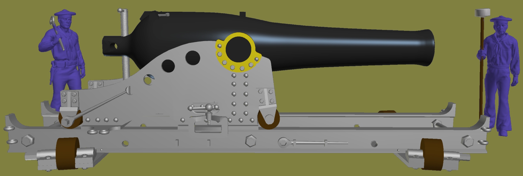
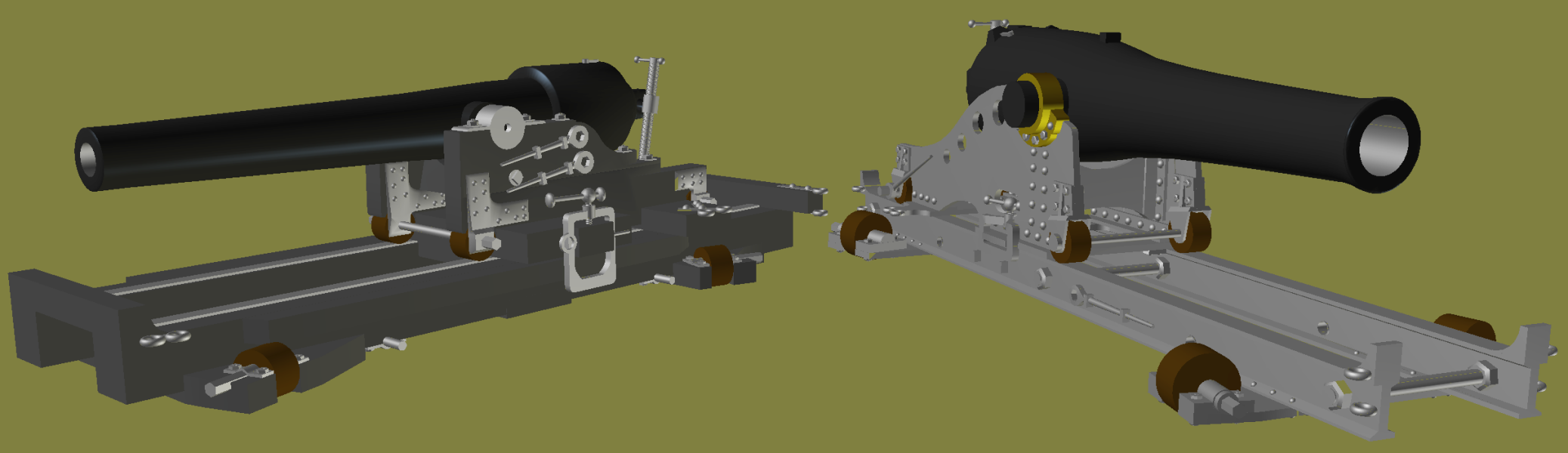
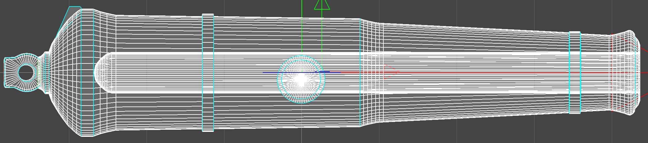
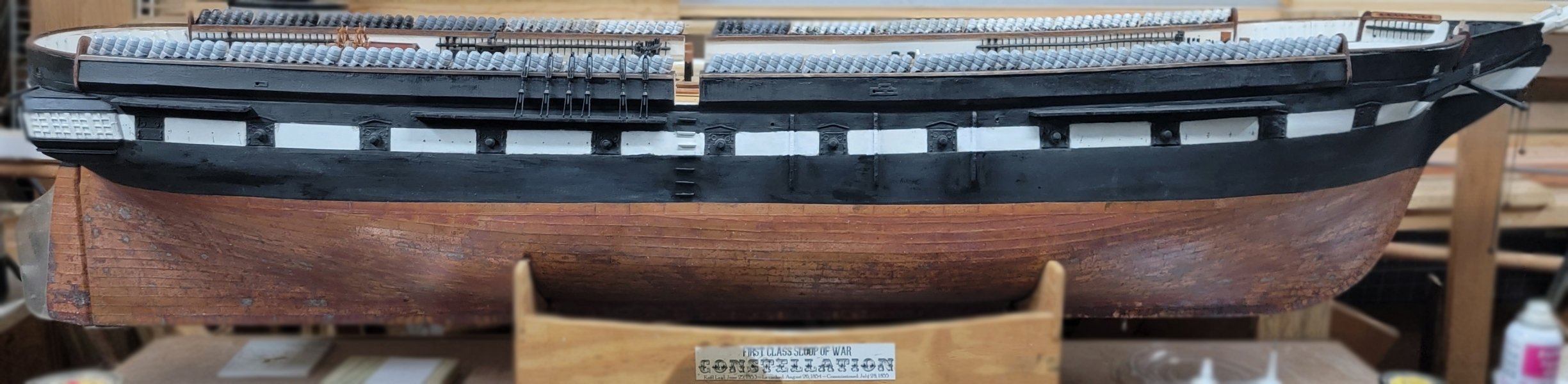
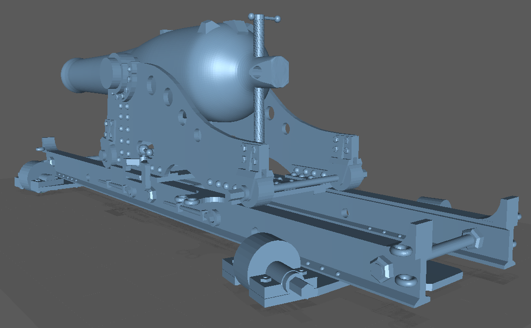
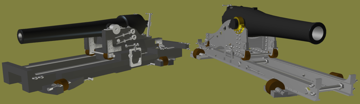
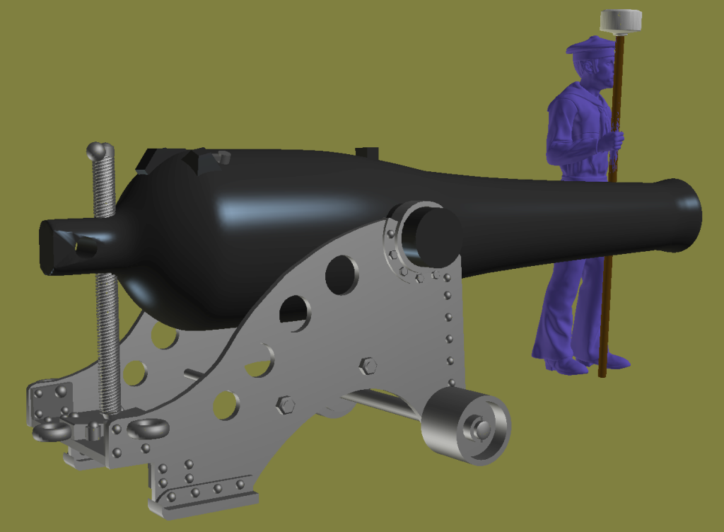
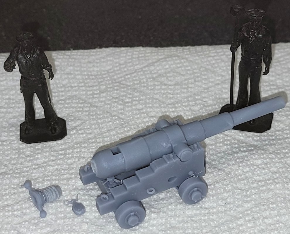
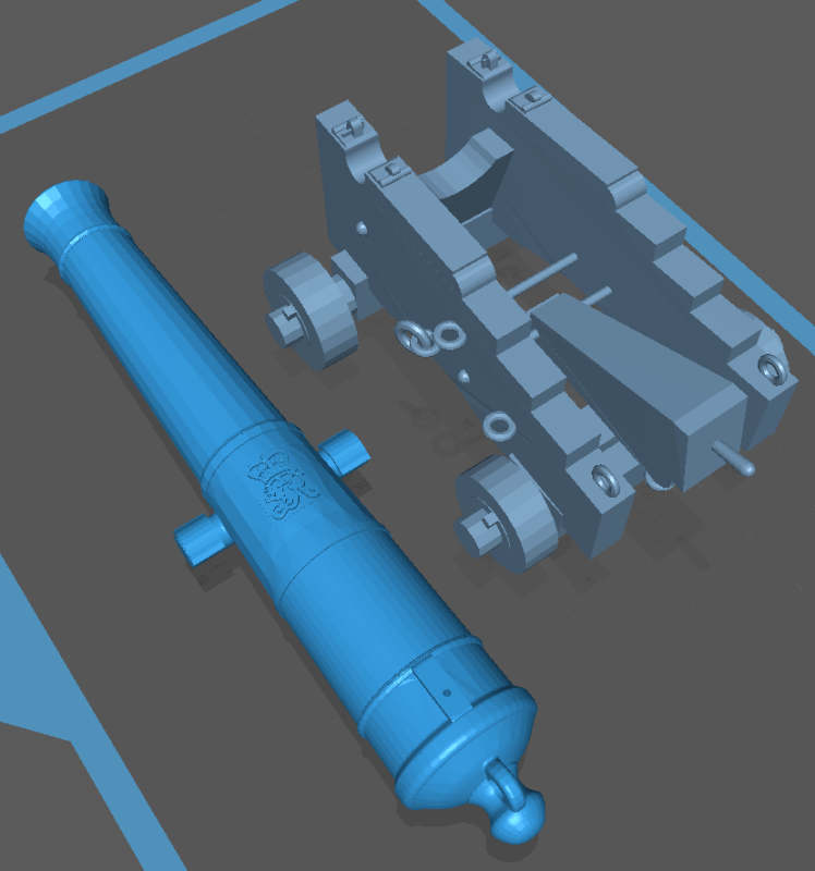
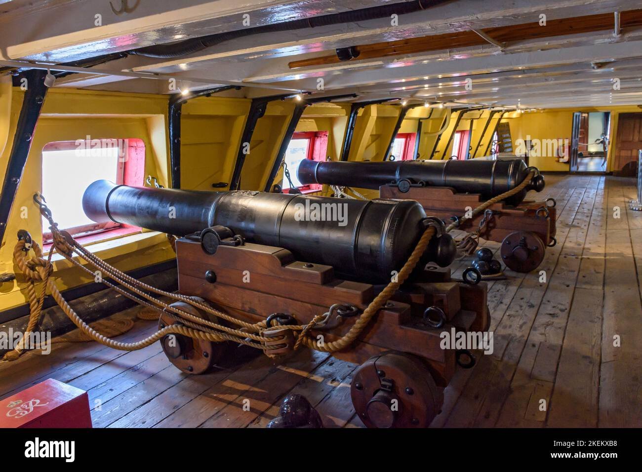
So I'm calling this one "finished" and posted it on Thingiverse. I may have to come back to it at some point, but till then... This model is of what I think is the first iteration of a wrought-iron pivot carriage for the XI inch Dahlgren. It would be altered over time, remove the compressors, adding recoil dampeners, geared devices for moving the gun on the slide, and so on. Many of these upgrades happened within the 1870's, the scope of my 3D Naval Guns 1850s-1870s project, but I don't plan on modelling them unless some incentive convinces me to. I am trying to compile a list of gun to look for in the National Archives, and plan to make a trip there, hopefull before Musk guts the place too. Many of the guns I've modeled so far, I haven't needed to actually print, for myself, at least, but Constellation did actually carry one of these for a time when she was a training ship, so I will eventually will be printing one for my Guns of Constellation project. When that happens, the pictures will probably go in that build-log. the two gun-deck pivots on-board Constellation in the 1870s; 100# Parrot & XI inch Dahlgren.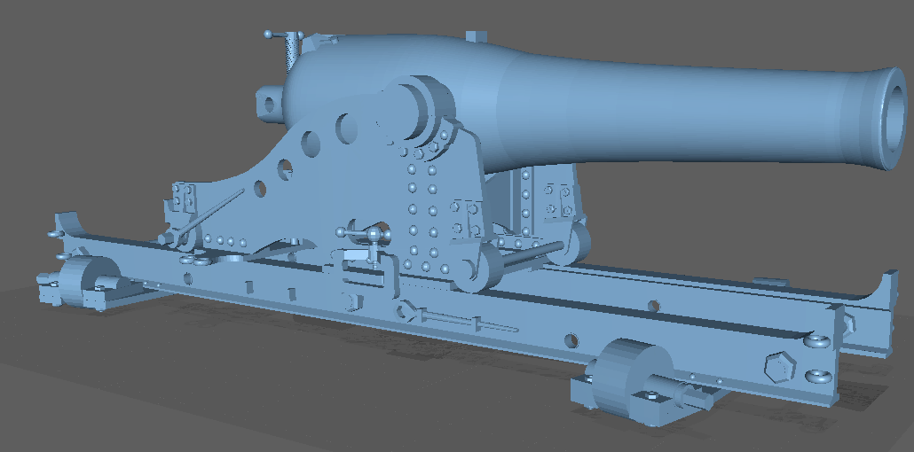
-
3D Naval Guns 1850s ~ 1870s
JerryTodd replied to JerryTodd's topic in CAD and 3D Modelling/Drafting Plans with Software
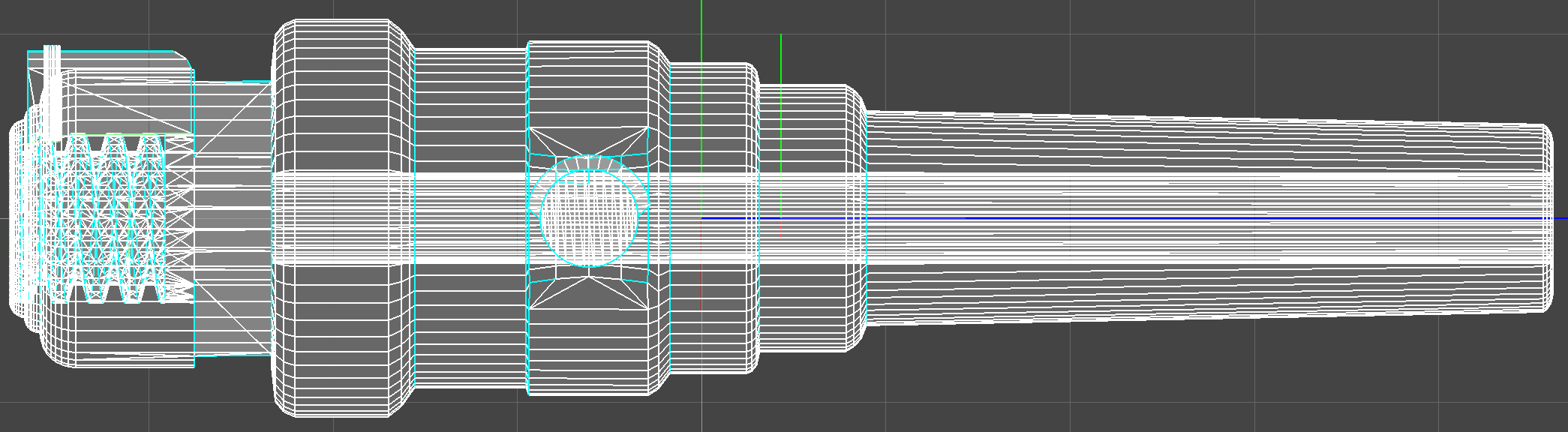
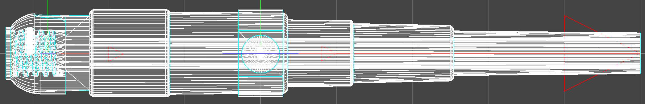
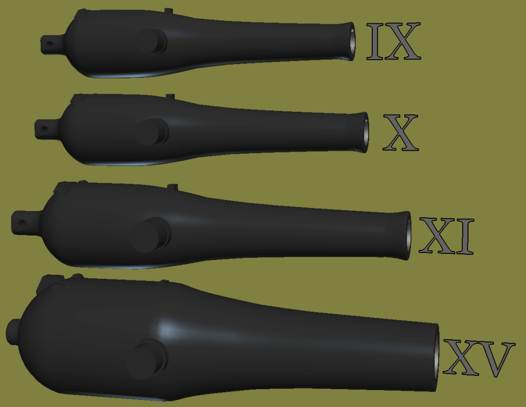
Finished up the XV inch Dahlgren I'm only doing the tube for this one, so I modeled in the touch-hole, elevation-screw hole, and a slot in the lobe where the firing mechanism goes.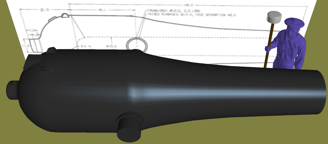
-
3D Naval Guns 1850s ~ 1870s
JerryTodd replied to JerryTodd's topic in CAD and 3D Modelling/Drafting Plans with Software
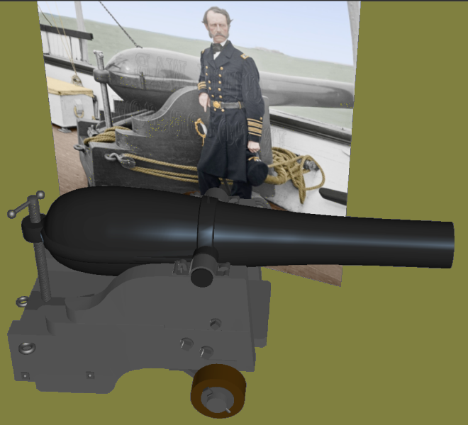
Any search for Dahlgren is bound to turn up a photo from a series that includes this one of John Dahlgren and one of his 50 pounder rifles: Since I had a good drawing in Arming the Fleet to work from, and it fits my time-line, I made one: I made the model match the photo, moving the aft eye-bolt up, and the files are posted up at Thingiverse.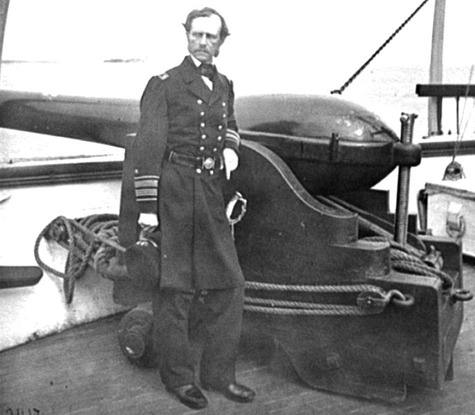

-
3D Naval Guns 1850s ~ 1870s
JerryTodd replied to JerryTodd's topic in CAD and 3D Modelling/Drafting Plans with Software
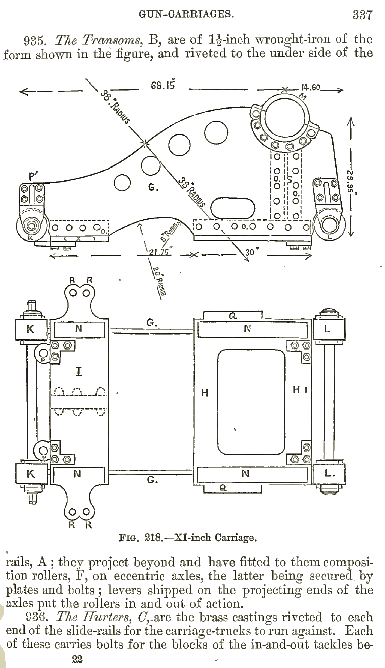
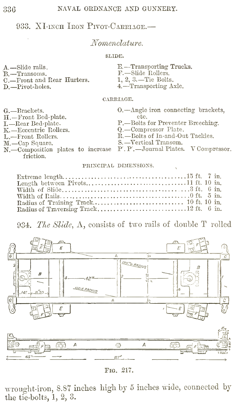
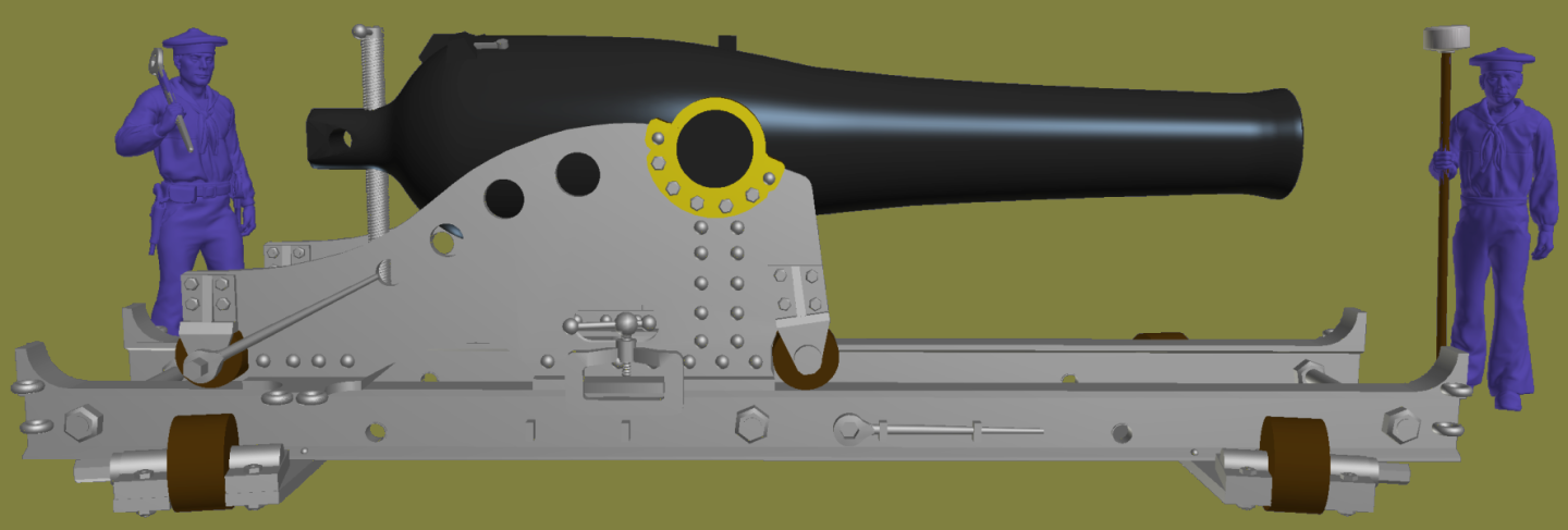
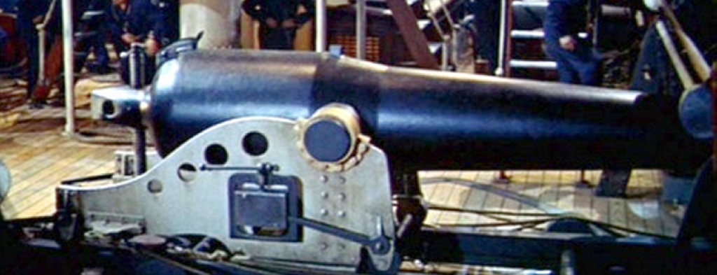
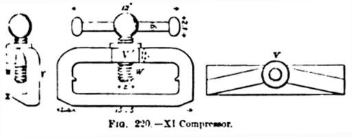
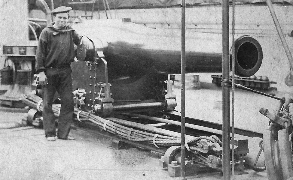
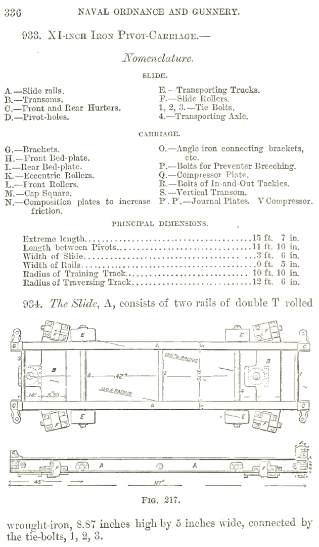
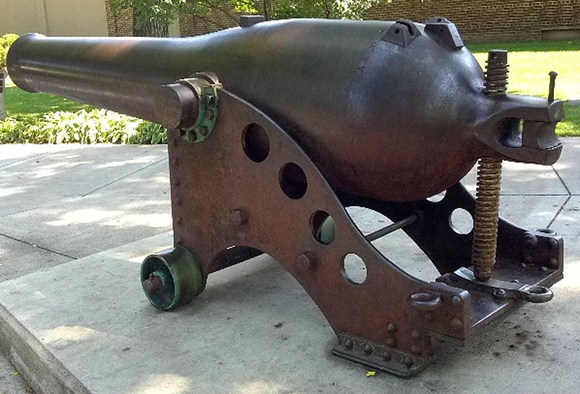
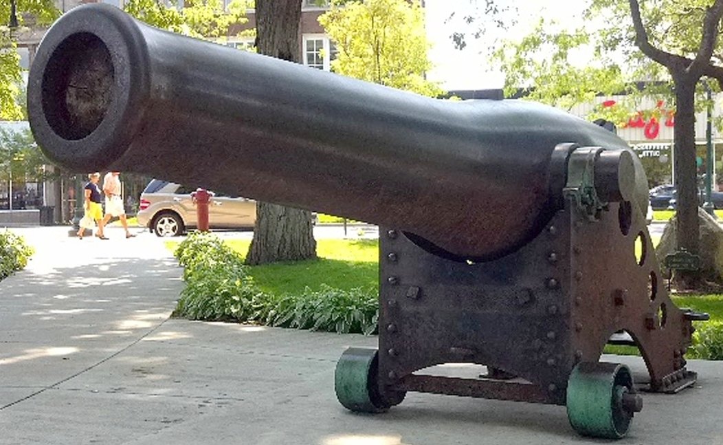
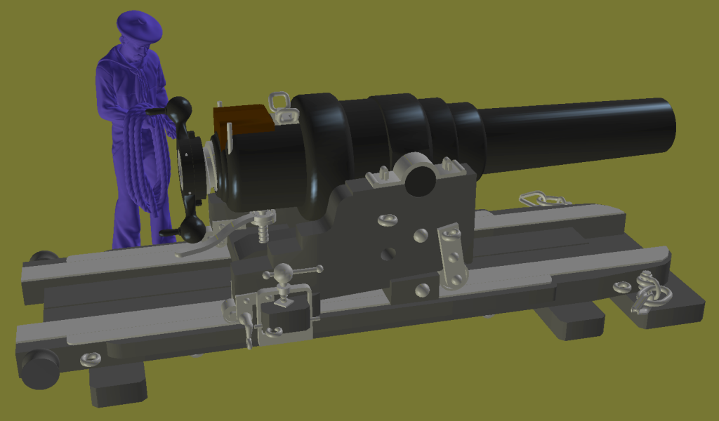
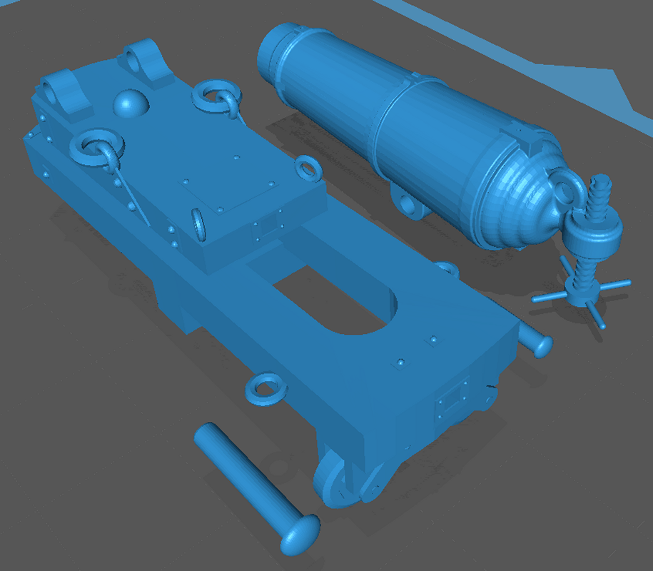
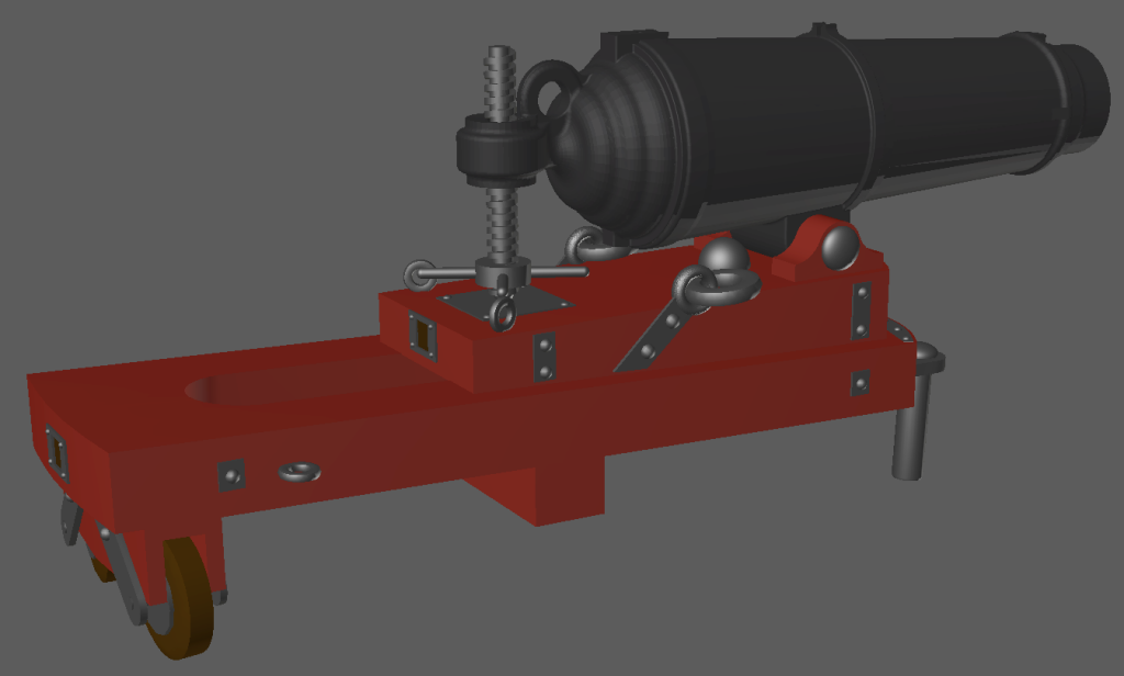
Back in post #7 I mentioned using a drawing from Deviant Art to start my XI Dahlgren on a iron carriage... Well, I finally learned it didn't represent any actual gun, gun rather a prop from the 1960s film 20,000 Leagues Under the Sea. It's a nice drawing, and a cool prop, but it's basically useless to me... But! I managed to turn up a scan of the 1875 Navy Ordnance & Gunnery manual on Google Books. This reference also helped me see things in photos I hadn't notice, or couldn't interpret, like the shape of the compressor... I basically had to rebuild my Iron Pivot XI Dahlgren nearly from scratch. There's still some adjusting to do, and details to add (and some to remove), but here it is so far...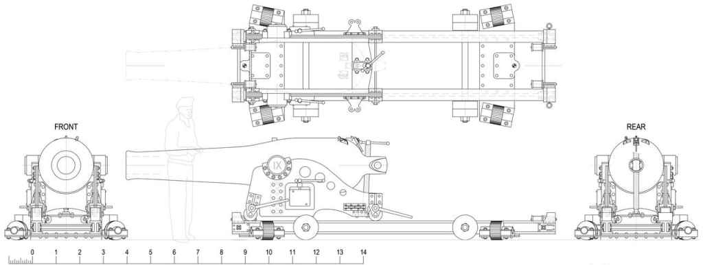

-
It's beginning to warm again which will hopefully mean physical progress. I want to get the joint between the hammocks and bulwarks dressed and trimmed out; properly and permanently attach the pin-rails; and continue making the chain-plates so I can get the shrouds and stays stood-up for the lower masts. The work will be almost all rigging at that point, but in fear of jinxing myself, we won't mention anything about being "finished." I was just got an email today inviting me to bring the models to a "School of the Sailor" being held May 18th at "Todd's Inheritance" at Fort Howard Maryland. I get more done when there's an impending event looming, so we'll see. After the personal events of last June, and the political events so far this year, I'm not counting on anything in the future being likely, much less, certain.
- 553 replies
-
- 1
-

-
- sloop of war
- constellation
- (and 3 more)
-
3D Naval Guns 1850s ~ 1870s
JerryTodd replied to JerryTodd's topic in CAD and 3D Modelling/Drafting Plans with Software
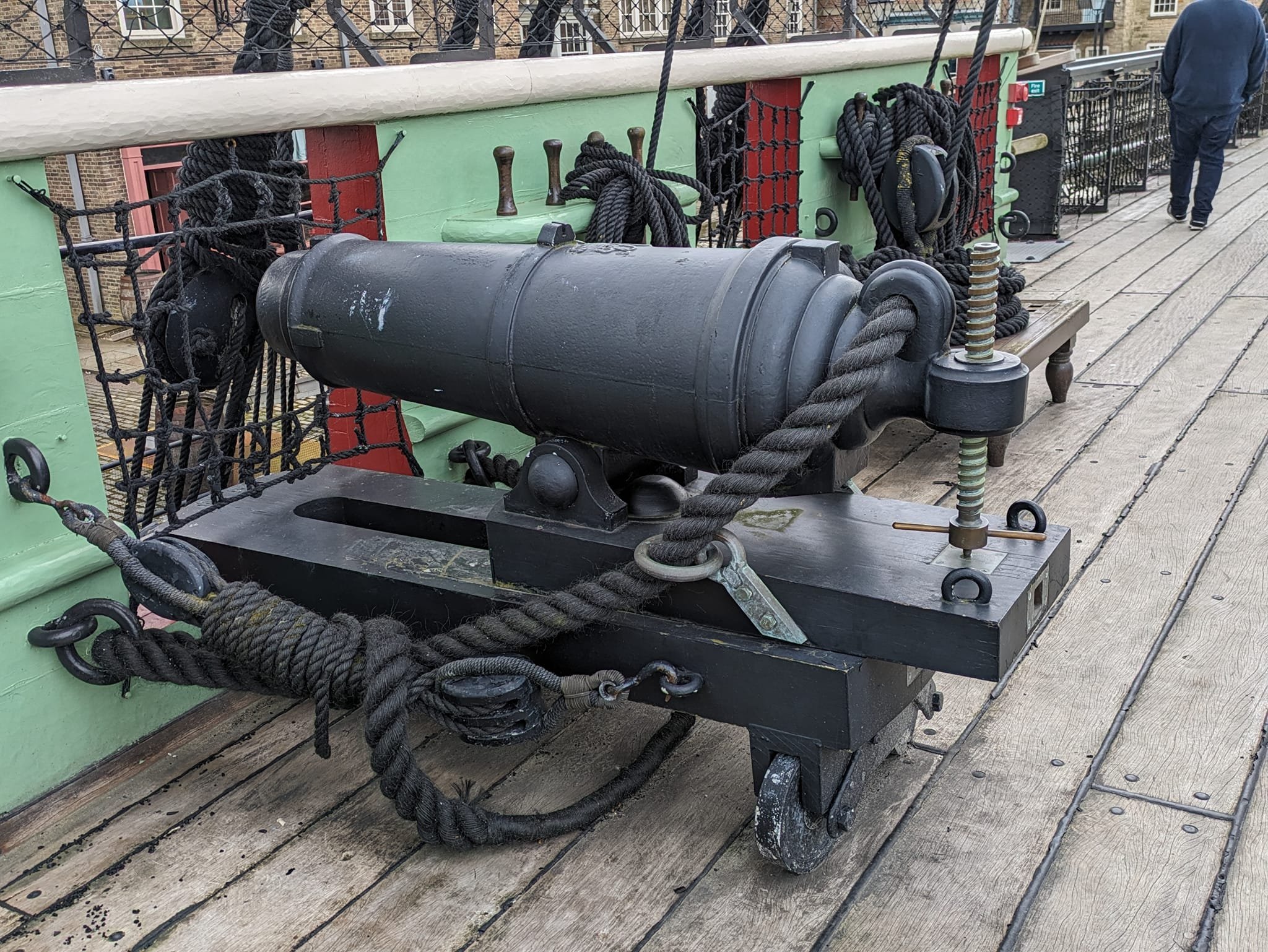
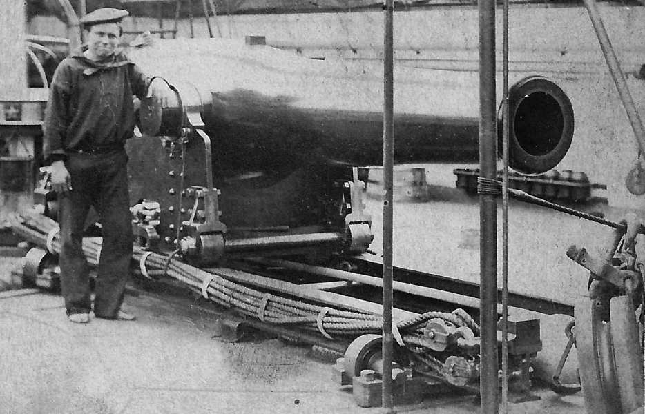
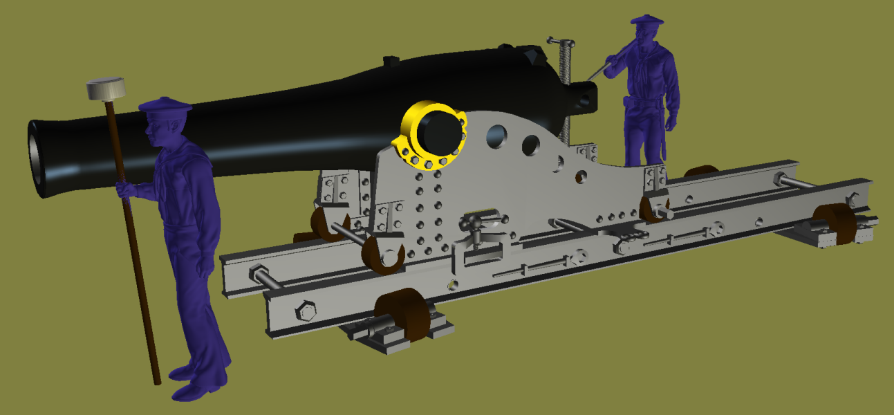
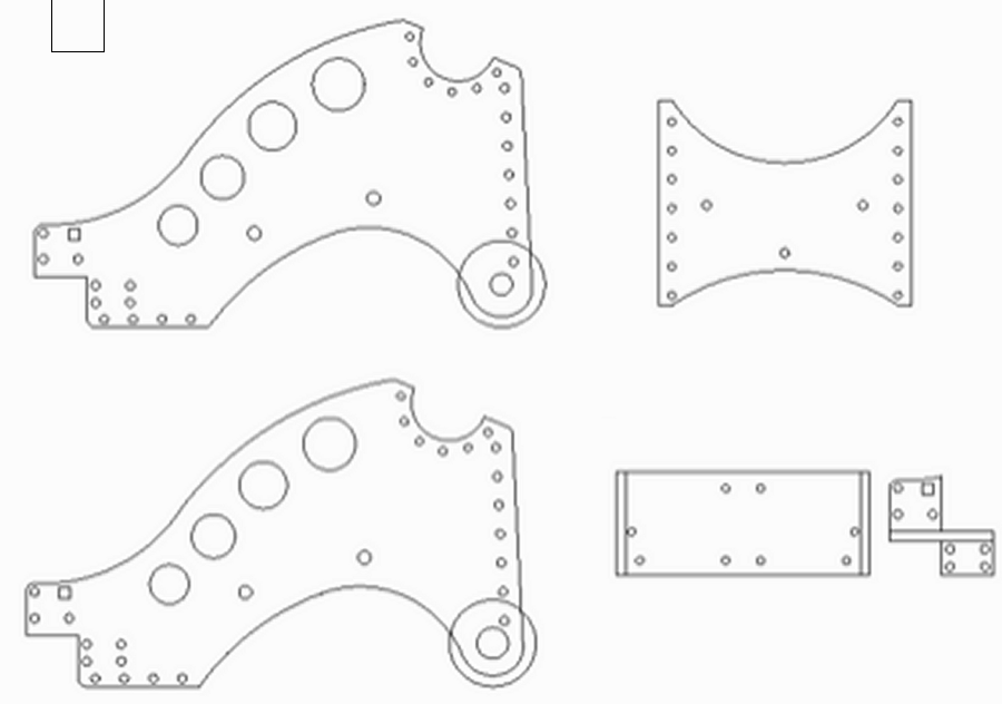
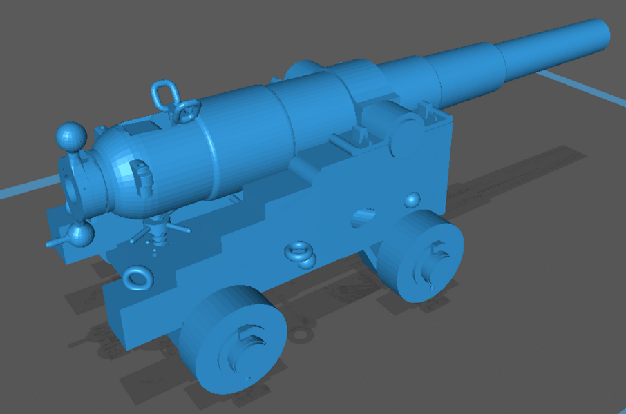
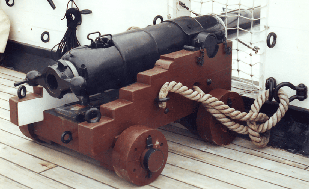
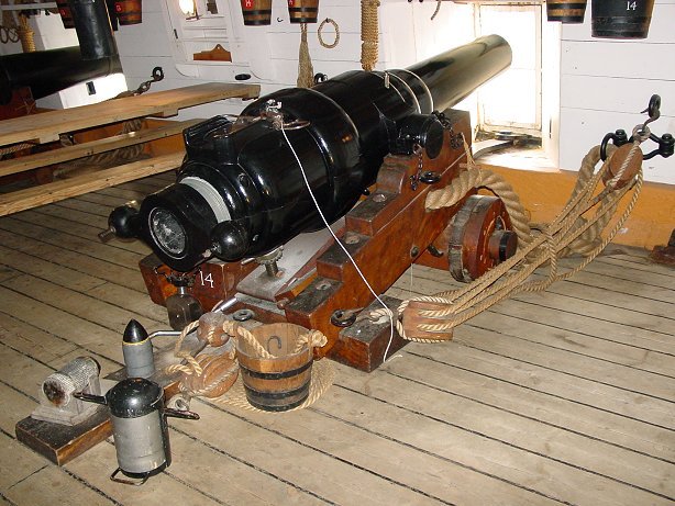
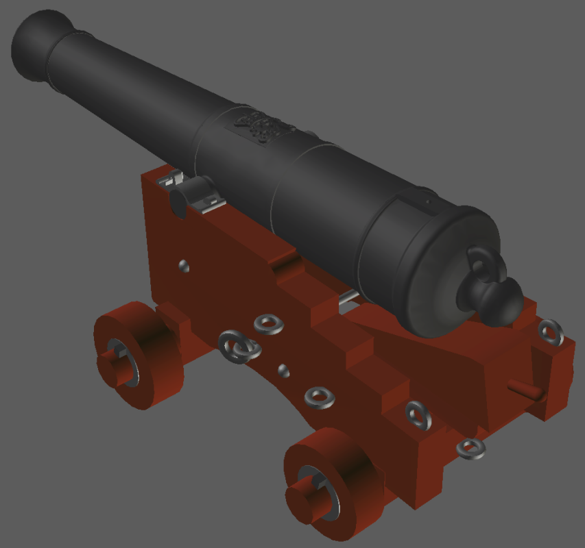
While searching for data on Warrior's gun carriages, or any guns, for that matter, I always find a few pictures of IX Dahlgrens on iron Marsilly-like carriages. So while another set of guns for another model of the Harriet Lane are on the printer, I began modeling this one. I'm amazed at how little good information is available for these guns. There's quite a few of them around, and some photos of them, but below, for instance, is the only image I could find showing the front of the carriage. I got excited when I found a nice drawing with 4-views, "full-scale" measurements, all the parts; but though it said it was this carriage, it was actually something conjured from someone's imagination, and not this carriage at all. Some fellow built a firing model of the gun and had the closet thing to a measured drawing I could find on his blog. This I scaled to the trunnions of my IX gun and basically eyeballed the rest from photos. Maybe it's not perfect, but it's looks pretty close to me.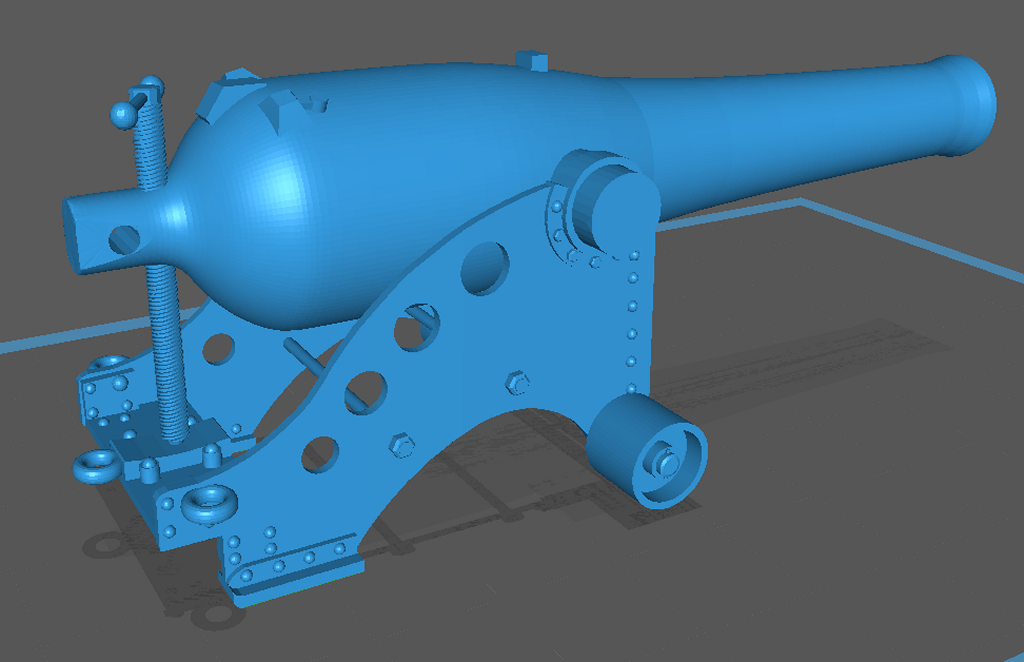
-
3D Naval Guns 1850s ~ 1870s
JerryTodd replied to JerryTodd's topic in CAD and 3D Modelling/Drafting Plans with Software
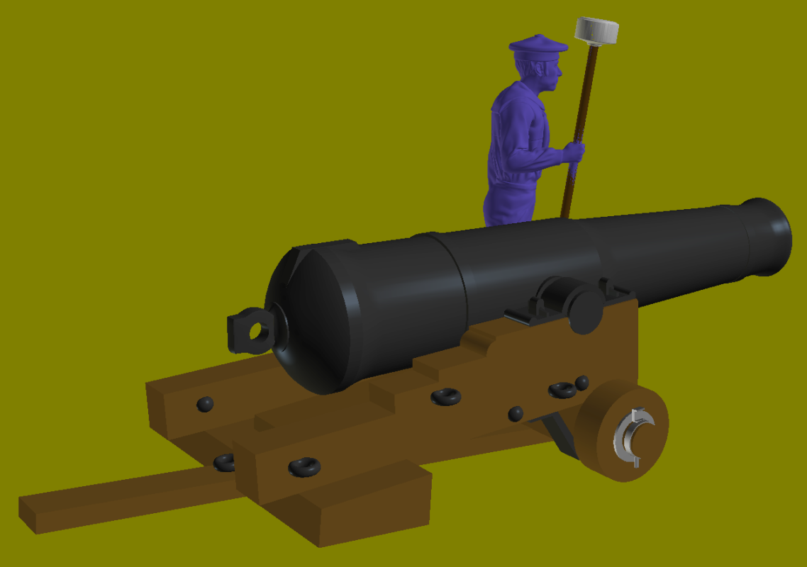
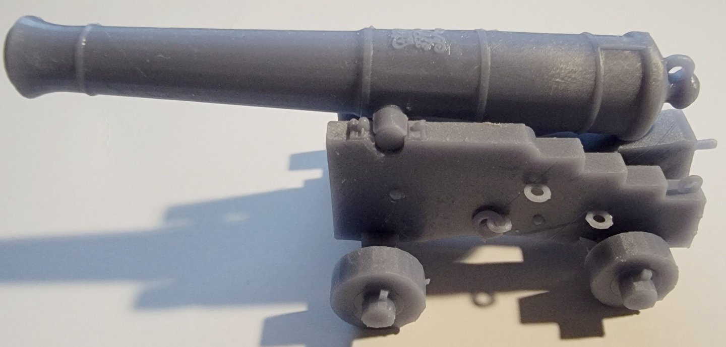
Wire-frame model of the 68 pounder smoothbore gun (still needs the front sight and rear site details) The carriage in-progress. I still haven't found any drawings, so I had to eyeball it from photos. In the slicer, just to check. When done, the barrel, carriage, and shifting-board will be separate pieces.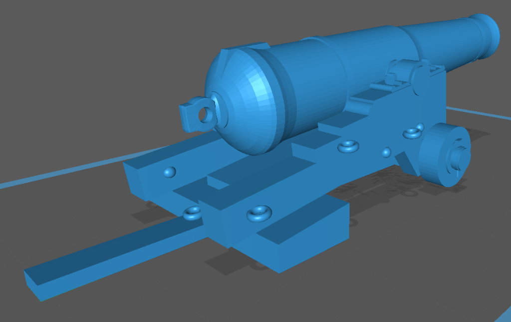

-
3D Naval Guns 1850s ~ 1870s
JerryTodd replied to JerryTodd's topic in CAD and 3D Modelling/Drafting Plans with Software
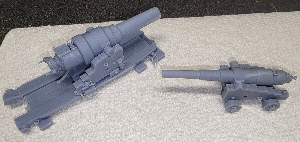
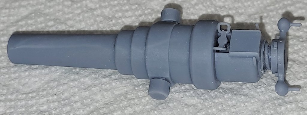
For some reason I thought doing another Armstrong was a good idea, so with drawings from Carlo in Italy, and some photos of the 40# Armstrong BLR on board HMS Warrior, off I go again. I repurposed the breech and breech-screw from the 110# BLR and went to work on the barrel. I make a long cylinder of a lot of segments and size the segments to the right diameters at the right places to form the barrel and it's bore from one "primitive." This gin with all its shapes are actually kind-of fun to do. (click for larger image) 110# gun 40# gun The 40# gun is much small than the 110#, but 1 inch longer. Warrior's sits on a 4-truck carriage. The print had some issues. The bails on the vent-piece almost didn't print, I forgot the make the "tray" on top of the breech for the vent-piece to rest when it was removed, and I added the sight-masses that Carlo sent. I haven't print this improved model yet, but it is all uploaded to Thingiverse. Before I print again, I want to try making the lever snap-on without requiring keeper-pins. So, while I'm on a "Warrior's armament kick" she also mounts Armstrong 110#s on a 2-truck carriage, and, I think 68# shell-guns, also on 2-truck carriages. I'm not aware of any other guns on the ship, so I guess I'll do these two next.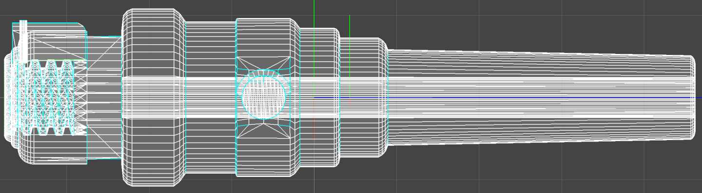
-
3D Naval Guns 1850s ~ 1870s
JerryTodd replied to JerryTodd's topic in CAD and 3D Modelling/Drafting Plans with Software
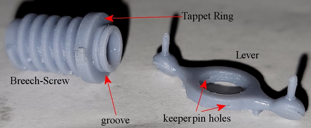
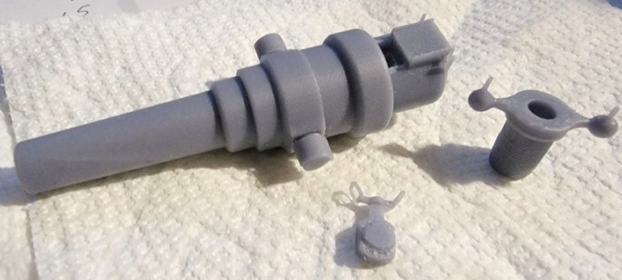
I printed the "breech-screw" and "lever" to see if it would print. The holes for the keeper pins were either too small, or closed up, and had to be drilled. The grove in the breech-screw came out nicely; I need to find some wire tiny enough to fit in there. The gun and it's carriage and slide came next. The slide came out a little gnawed on in one corner, but otherwise everything printed well. The coarser threads worked great and should scale down well. The lever/breech-screw combo probably won't, so I made a one piece lever/breech-screw piece. (click to see fullsized) The gun and it's carriage and slide came next. The slide came out a little gnawed on in one corner, but otherwise everything printed well. The coarser threads worked great and should scale down well. The lever/breech-screw combo probably won't, so I made a one piece lever/breech-screw piece It's all been posted on Thingiverse I think I'm done with this one for now, and need a break, and stick to muzzle loaders.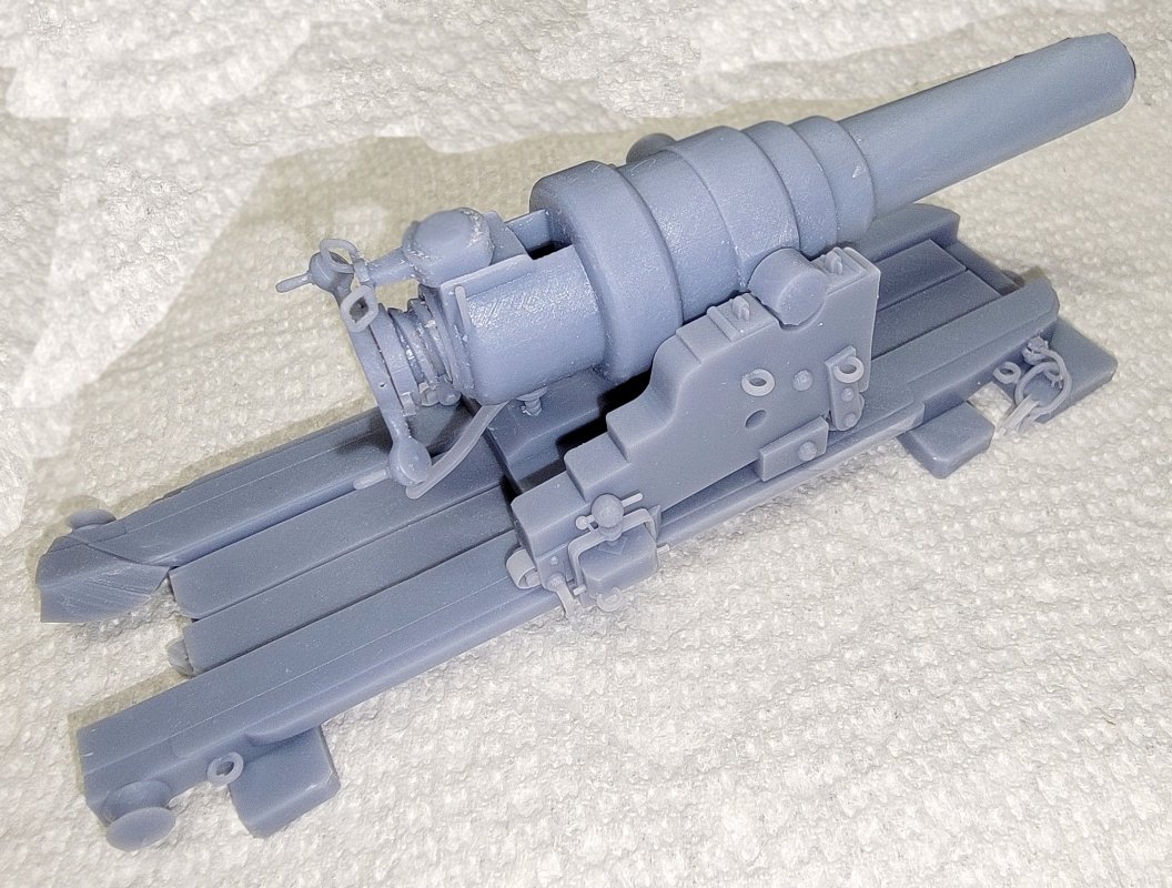
-
3D Naval Guns 1850s ~ 1870s
JerryTodd replied to JerryTodd's topic in CAD and 3D Modelling/Drafting Plans with Software
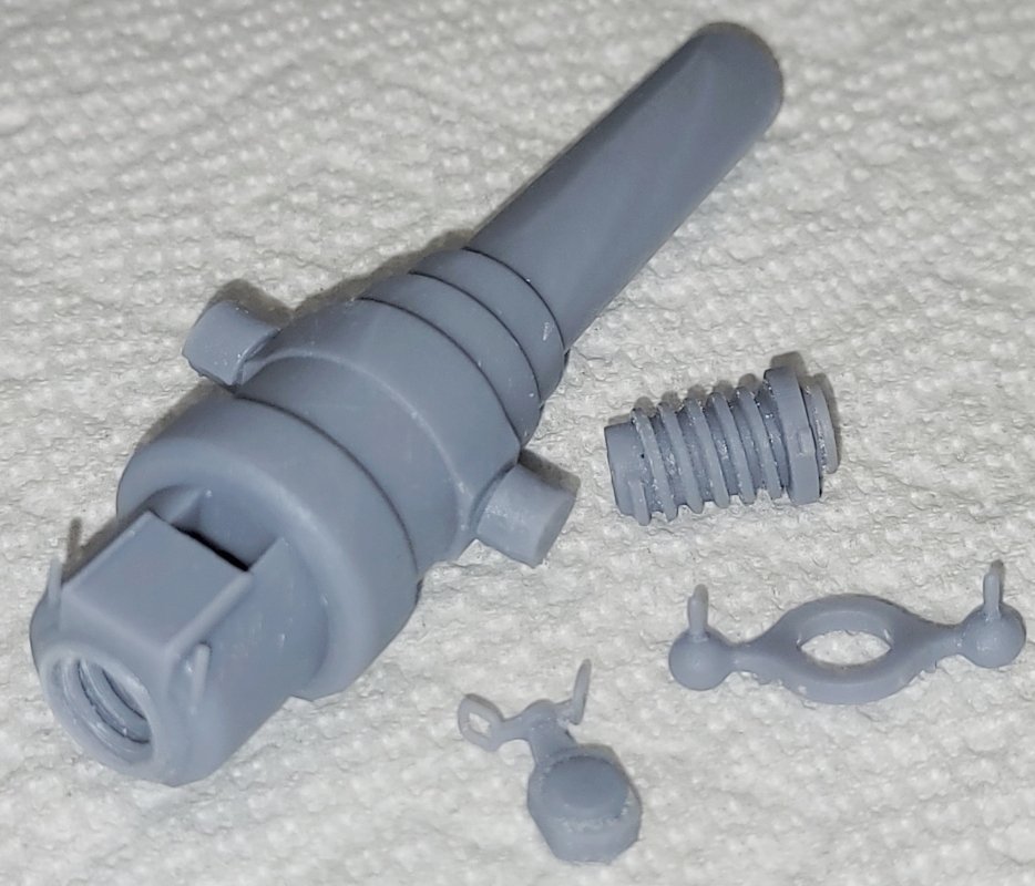
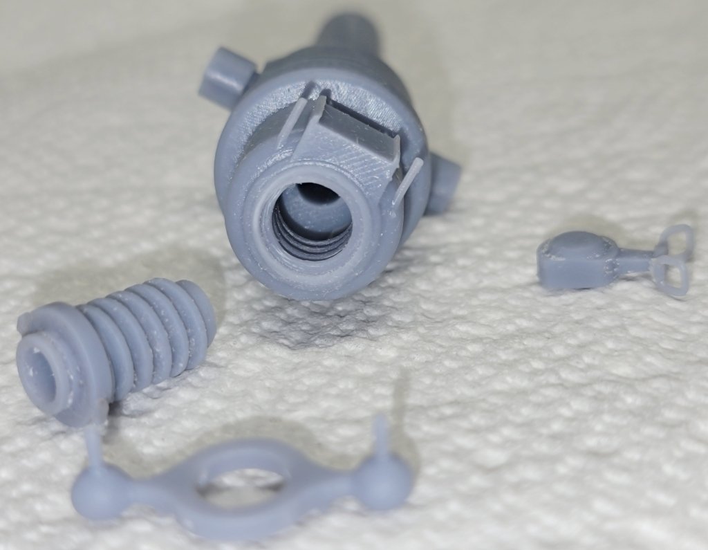
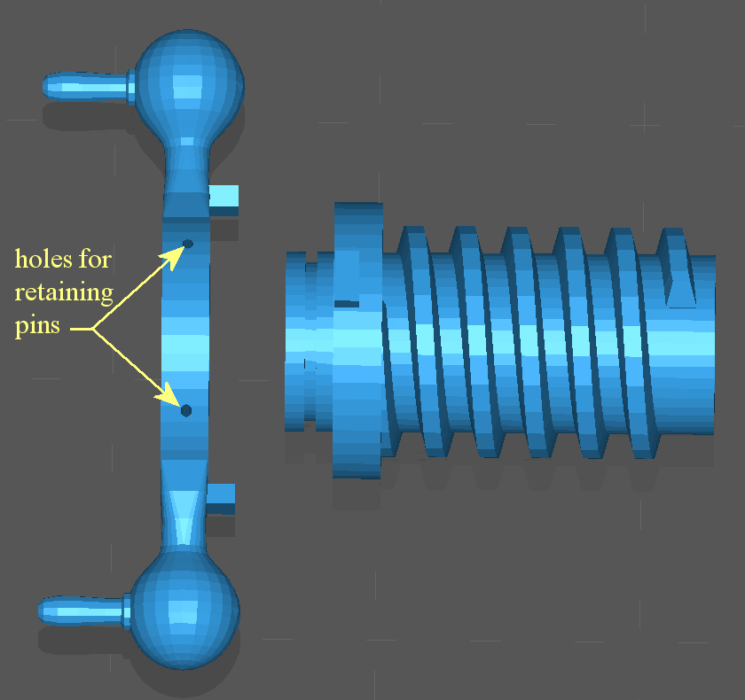
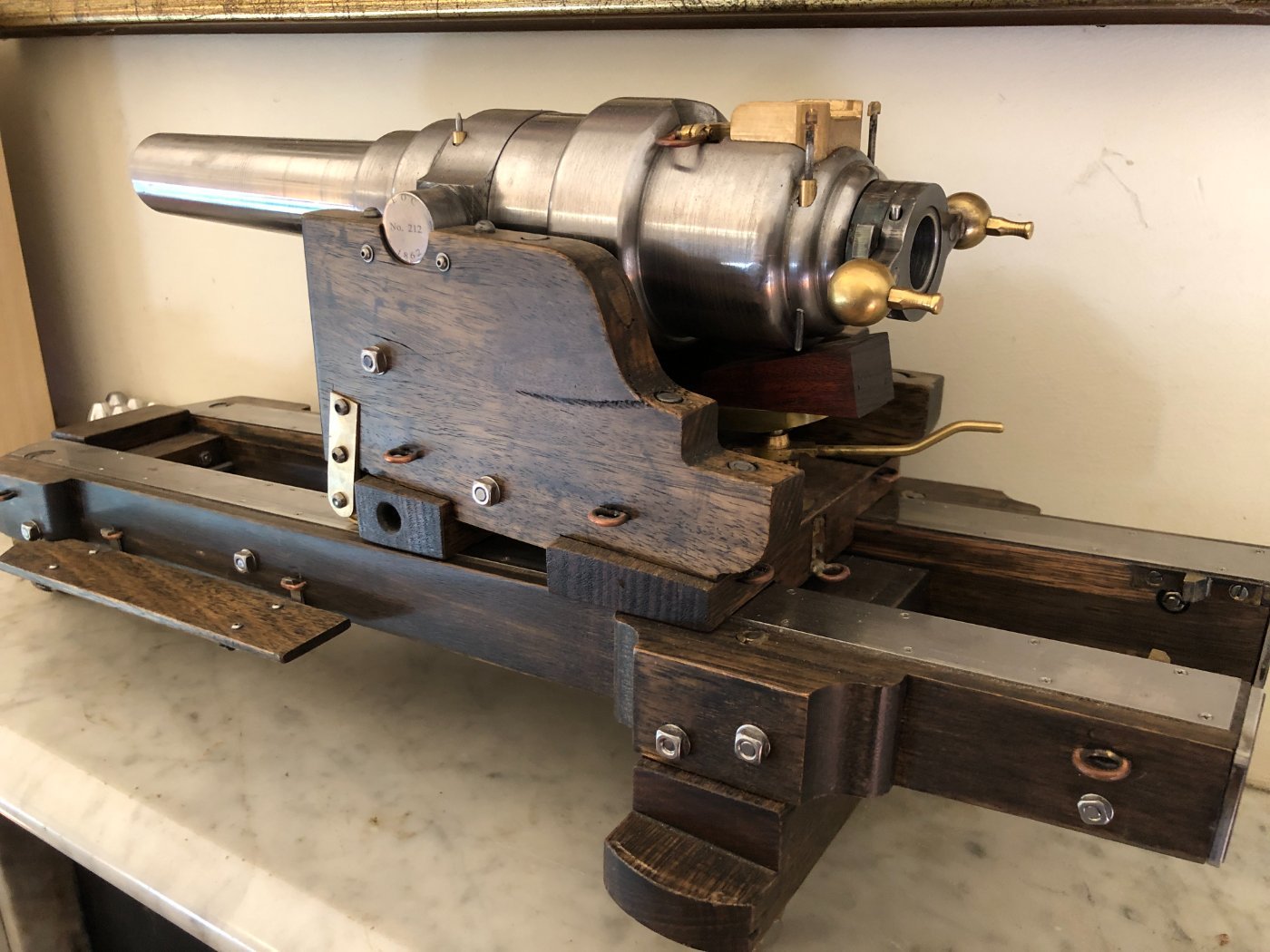
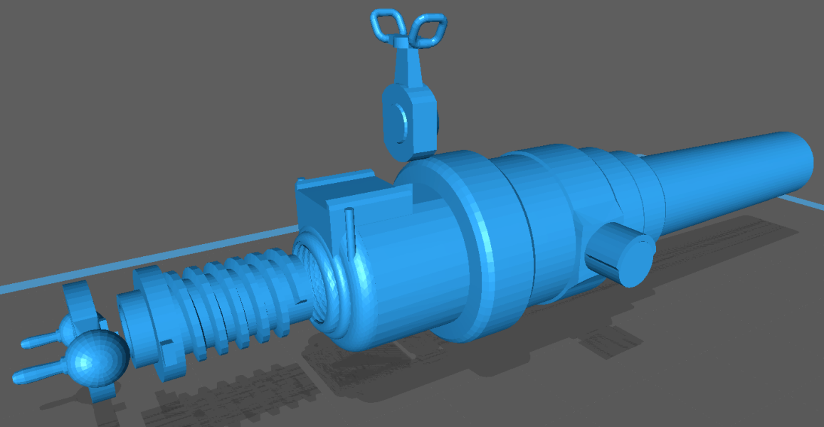
A conversation of 3D printed guns got me returning to the Armstrong 110# BLR. I've been working on a carriage and slide for it, but I decide to upgrade the gun tube now as well by making the breech loading characteristics funtional-ish. An Italian fellow (Carlo) that loves to draw artillery in AutoCAD sent me some drawings he made, and an Australian (JohnV) fellow that posted images of a beautiful (probably working) model, that he built; both of which helped me with details I didn't see before or interpret correctly. This model helped me finally figure out the breech mechanism. The first order of business was making the breech-screw removable. At first I was going to make it smooth and just friction fit into the breech, but Carlo shared an STL of his breech and the breech-screw with the proper threads with me. I scaled these to 1:36 scale and 3D printed a test. It worked, but the threads were very fine and took some hand work to make work. If printed at 1:76 or 1:96 I don't think it would work at all. At first I figure to make the original smooth plug idea for smaller scales, but decided instead to make coarser threads instead. My 3D software isn't the best for things like screw-threads, but I found STLs for a lead-screw and nut on Thingiverse, and adapted those. Putting the threads on the breech-screw was pretty straight forward, but removing the threads inside the breech and installing the ones that hatched the breech-screw was not. It turned out to be faster and easier to make the whole breech from scratch. I think that bit's pretty much done, though I haven't printed it yet to test. If you watch this video of the 110# Armstrong at Fort Nelson, UK, being load and fired, right-off you'll see them spinning the breech-screw with the handles on those pawn-shop balls. Loading & Firing the 110# Armstrong Gun What's interesting is that doesn't spin the breech-screw, it just spins on the end of the breech-screw until a set of stop-blocks hit and hammers the screw-breech open, or closed. If you look closely at JohnV's model above, you can get an idea of how it's put together, well I did; and so I'm incorporating that feature into my model. Anyone that prints this gun will have to insert two pins in the pawn-shop balls part to hold it on (you can see those in JohnV's model). I don't know if that detail will survive scaling the model below, say, 1:48 scale. Folks may have to just glue that bit together at smaller scales. There's still details to ad to the carriage, slide, and even the gun before I have a go at another print. If they goes well, it'll get posted on Thingiverse.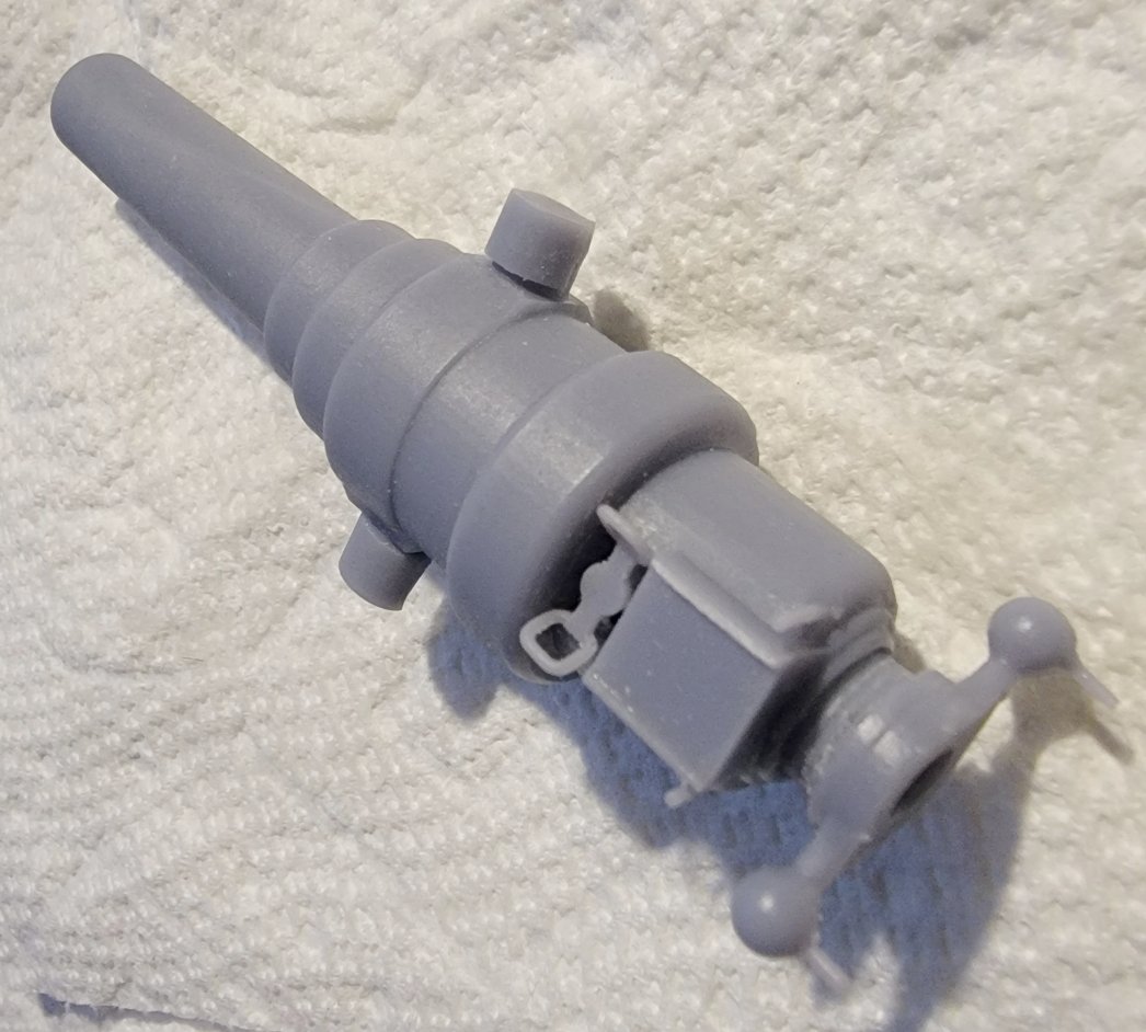
-
I was going to say something about how well the printer's doing, but I'm afraid I'll jinx it.
- 97 replies
-
- 1
-
-
- macedonian
- frigate
- (and 2 more)
-
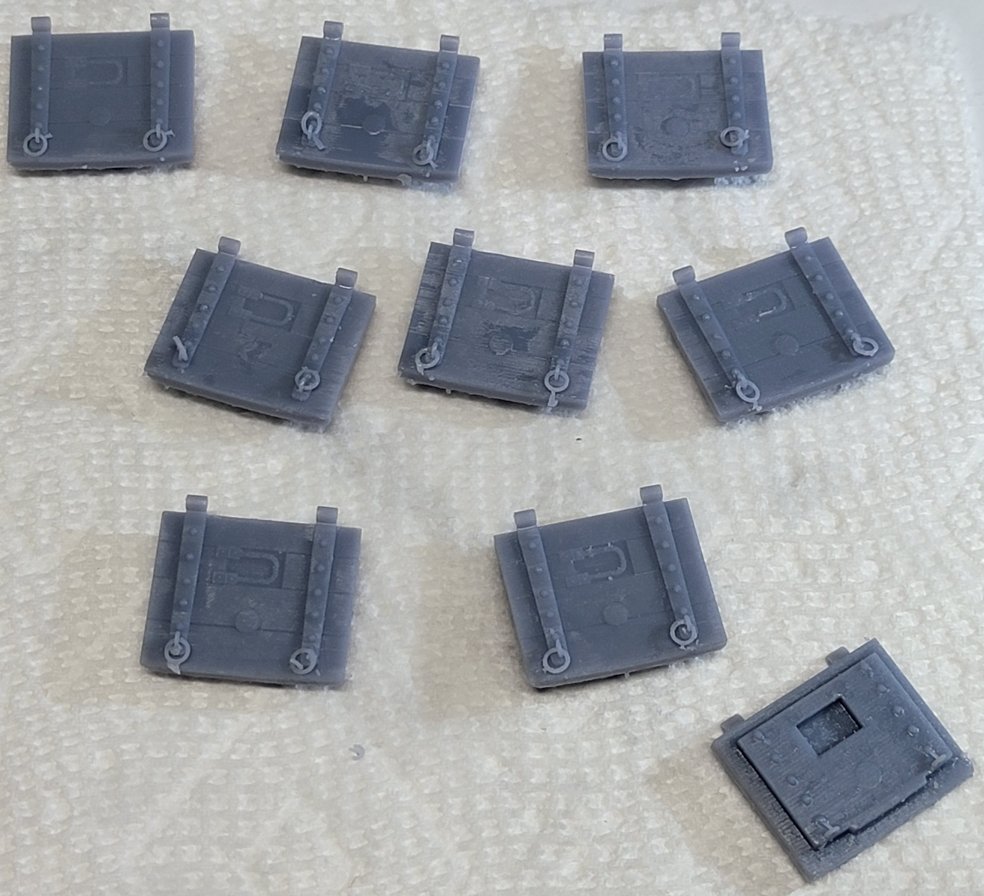
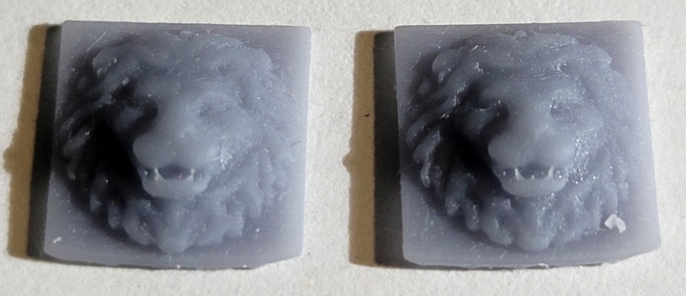
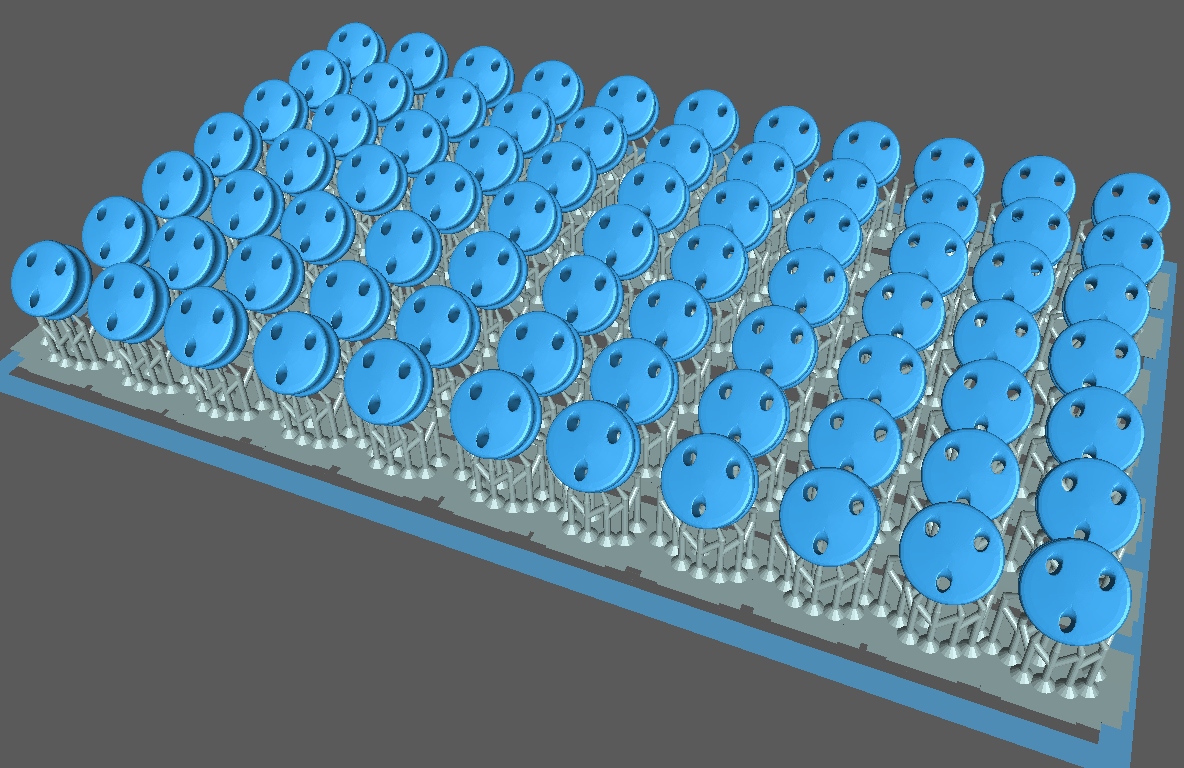
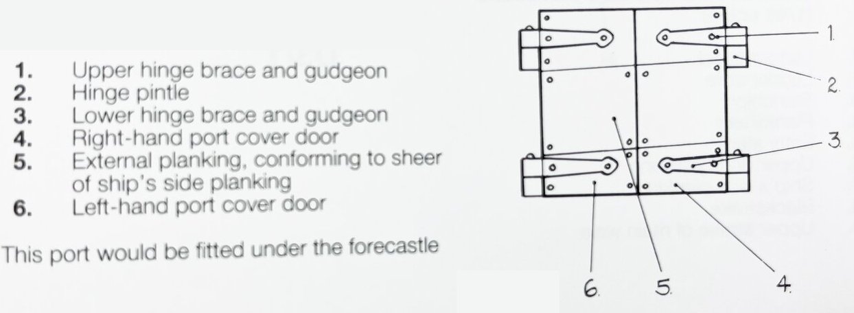
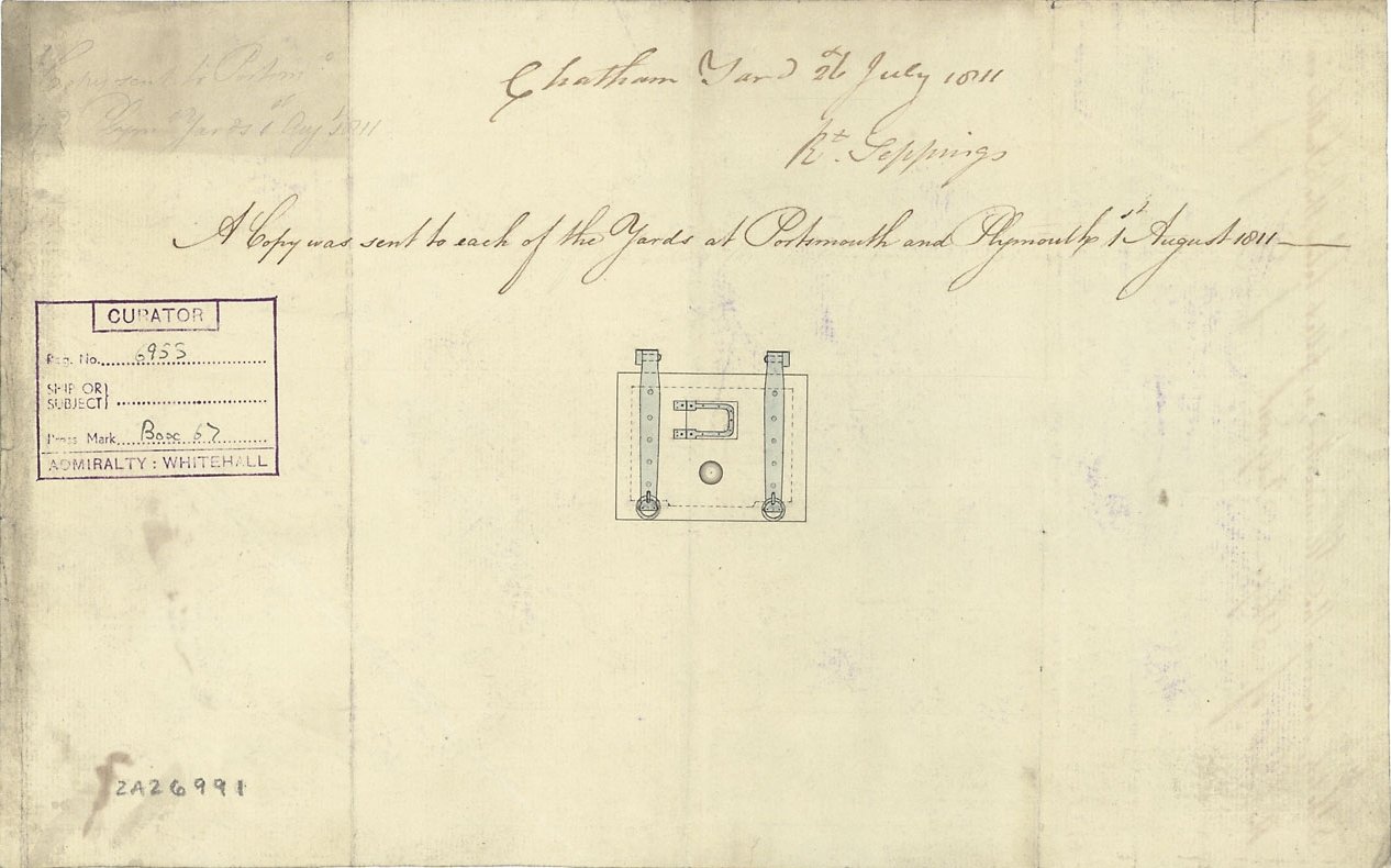
I looked for data regarding gunport lids all over MSW, the net, and in my books, with no real luck. Everything is Victory and Constitution, I couldn't even find good images of Trincomalee or Unicorn as references for a frigate's gunport lids. I did find a drawing at NMM, basically a memo for gunports dated 1811. Macedonian was launched in 1810, so I don't know how appropriate would be to my model, but I doubt it's too far off. click it see see it full size So I cobbled a 3D model of one together, and printed a few just to see. I probably need to make some adjustments before printing a full set, but I think they7 do the job. They don't need German optics kind of tolerances since I plan to have the guns run-out and all the lids open. The two gunports most forward are "catting-ports" and get split lids because a lifting lid would be in the way of fishing up the anchor, etc. Haven't made those yet... I also stumbled over a lion face door-knocker STL file and though I could use it for the cat-heads. I tossed some of it's "embellishments," like the knocker, flattened it, a lot, and put a square block behind it. In my scale it's 1cm square, about the size of someone's pinky finger-nail. The other item I made are dead-eyes. There's 6 different sized ones just for the lower shrouds and stays, and I'll have to guess at the top-mast shroud sizes. I printed a few of the largest ones, I'll save the rest till I need them.
- 97 replies
-
- 4
-
-
- macedonian
- frigate
- (and 2 more)
-
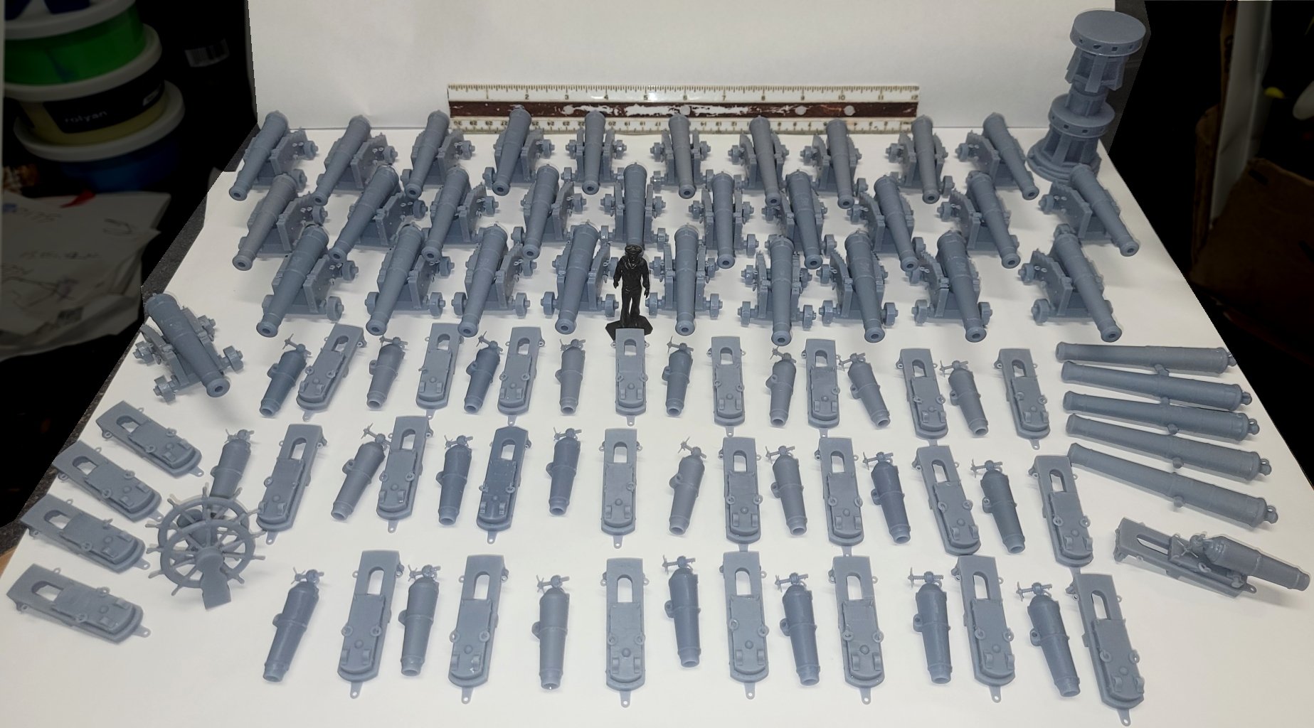
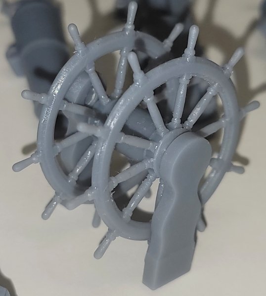
Still things to build and print for Macedonian, but the guns (and some extras) are printed, the capstan, and the ship's wheel: It's still below freezing here, so priming and painting will have to wait. Some 3D things yet to make? Blocks, hearts, bullseyes, fairleads, dead-eyes, crew figures, stuns'l irons, binnacle, pin-rails, cleats, ship's boats & boat-chocks, decorative carvings (I plan on modeling the entire transom and quarter galleries), and barrels, boxes, & what-not as needed. The next non-printed thing this model gets is wood padding around all the gunports and ceiling planking from the gun-deck up so the hull can get painted and at least start to look like a boat.
- 97 replies
-
- 3
-
-
- macedonian
- frigate
- (and 2 more)
-
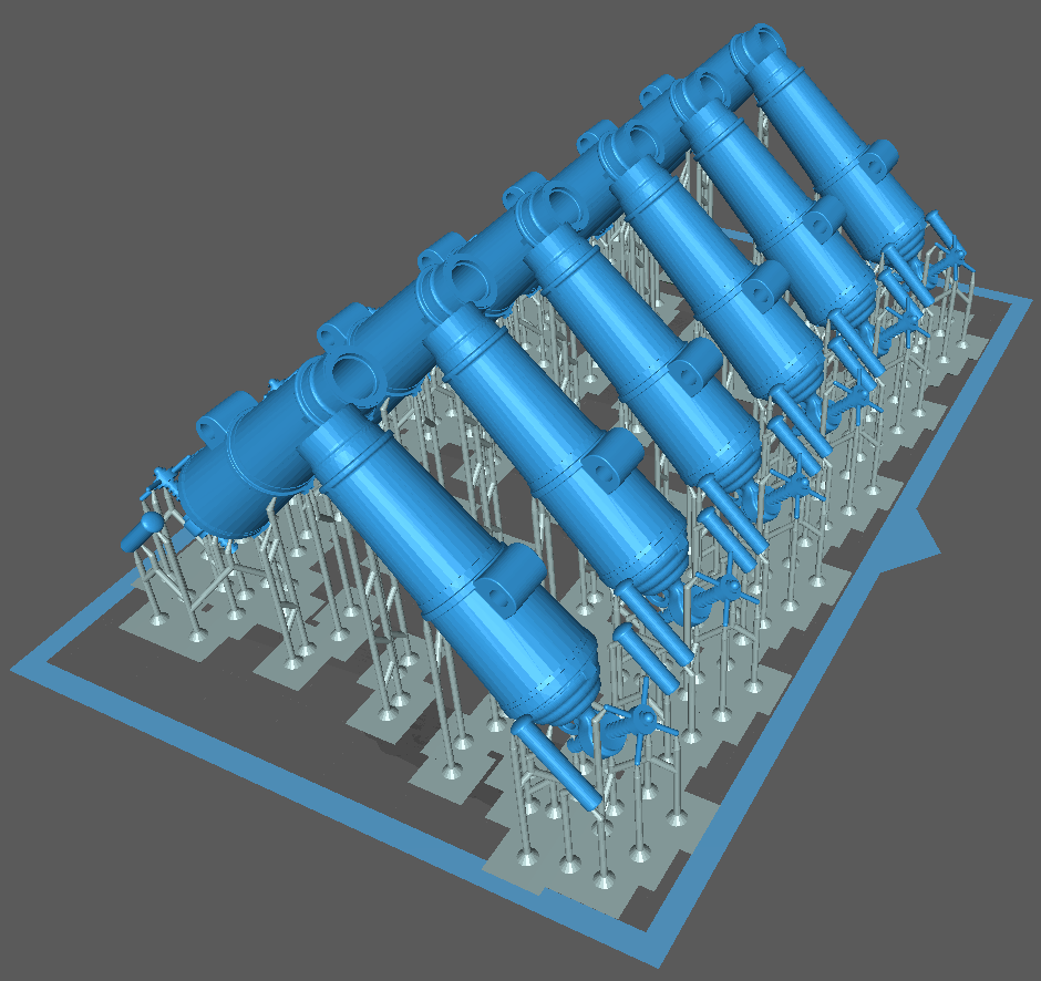
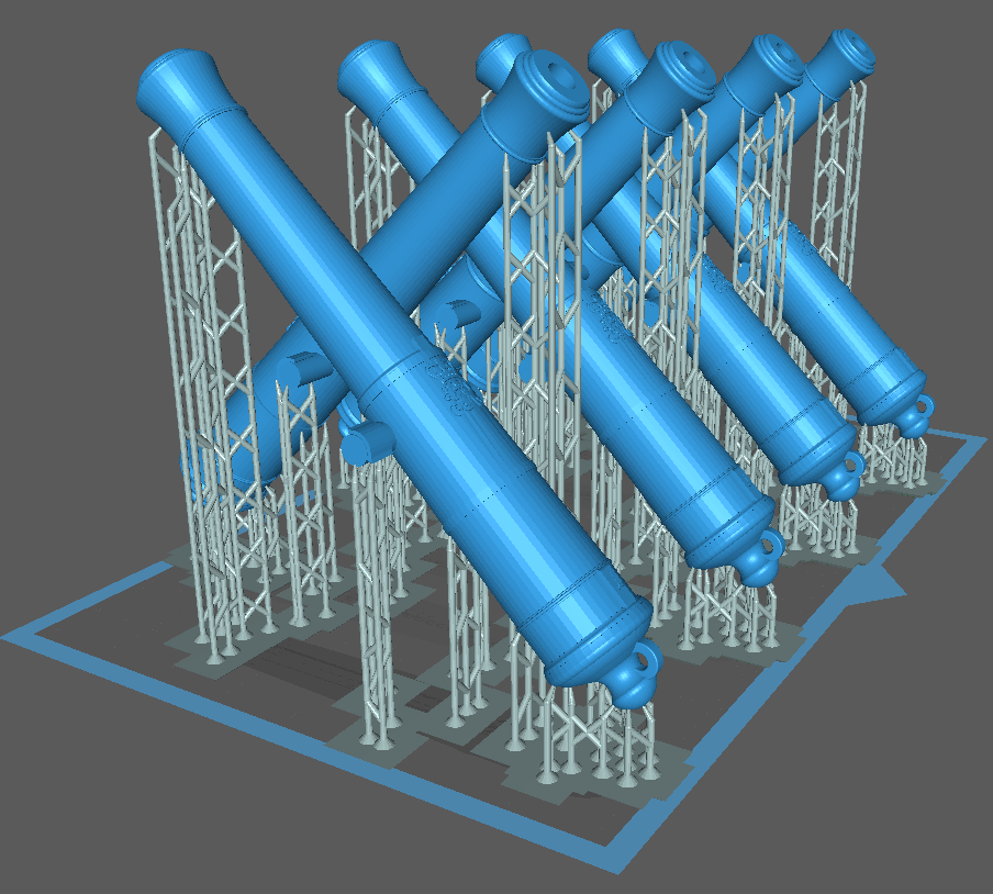
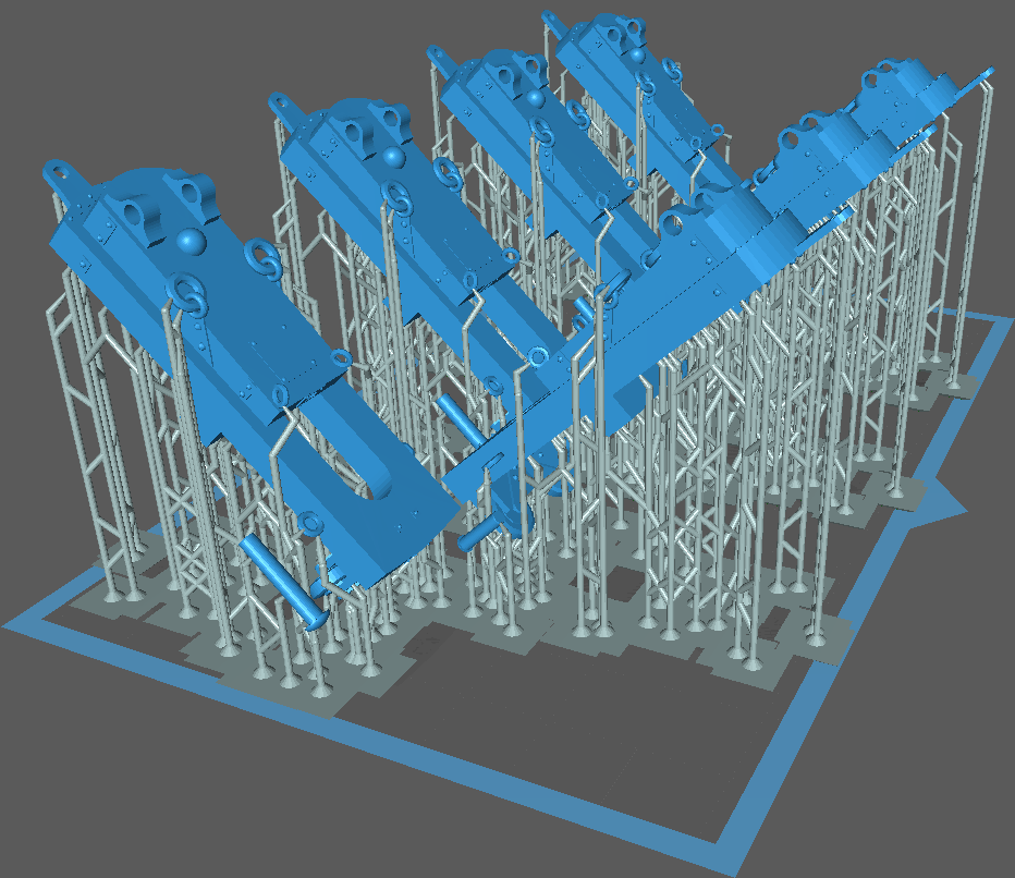
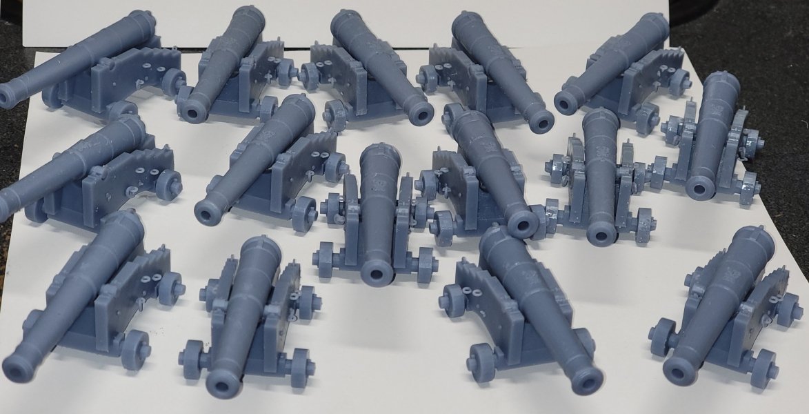
I can fit 5 carriages on the plate, angled at 45° takes about 2:25 hours 8 tubes at 45° are taller and take just over 3 hours. 7 carronade slides take 2:10 hours, and a dozen carronades are a couple of minutes take 1:56. "For those watching at home;" print time is based on layers, so the taller something is, the more layers it will have and the longer it takes (that includes the supports). Otherwise how much in on the plate (the blue box in the pics) has no effect on time; though it obviously effects the amount of resin used. The parts have to be angled to keep the surface area of each layer to a minimum or the wrong side will win in the tug-of-war between the plate/supports and the bottom of the vat.

- 97 replies
-
- 1
-
-
- macedonian
- frigate
- (and 2 more)
-
So, I've been printing cannons in between other things and have all the 18 pounder tubes I need, but only 15 carriages so far. and half the carronades with their slides.
- 97 replies
-
- 3
-
-
- macedonian
- frigate
- (and 2 more)
-
How did it get to be so many years so quickly?
-
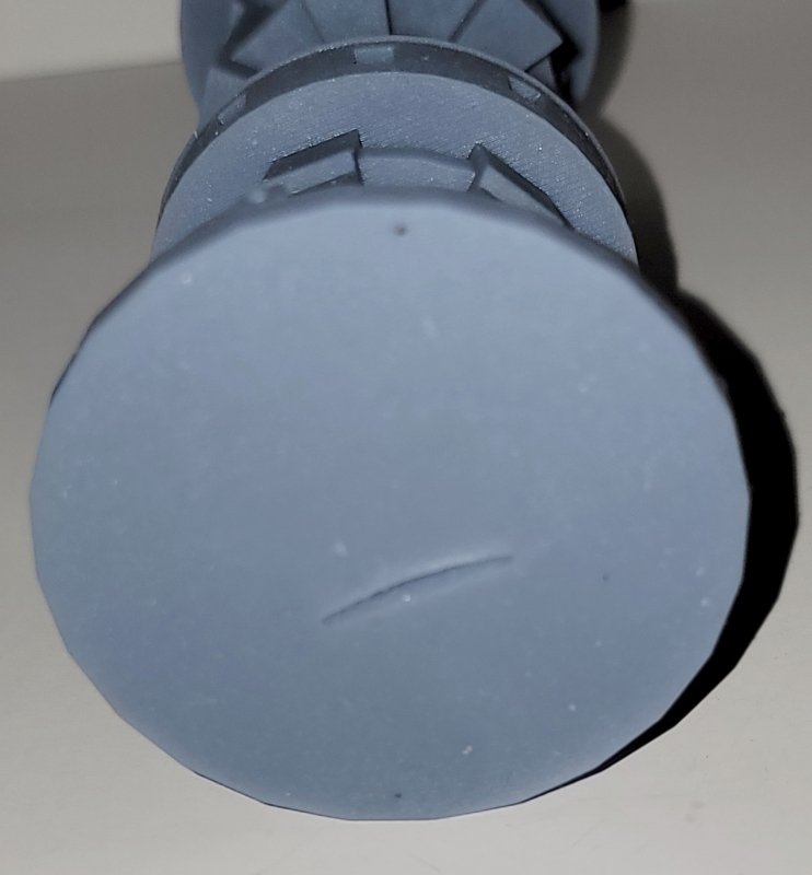
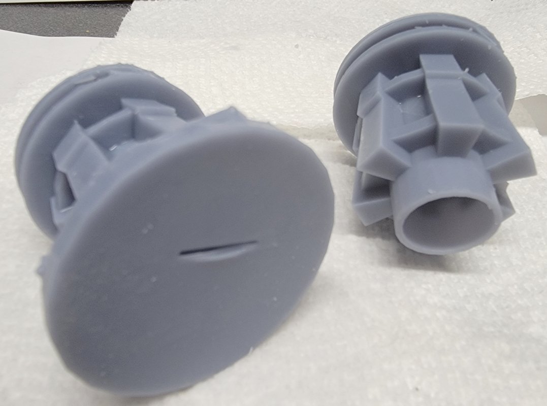
This time I got a nearly perfect print but for some reason it printed over the hole at the bottom with the same gash in it as the first print had. I'm not printing it again, so I'll drill out the hole, or maybe put in a pin so it can spin.
- 97 replies
-
- 4
-
-
- macedonian
- frigate
- (and 2 more)
-
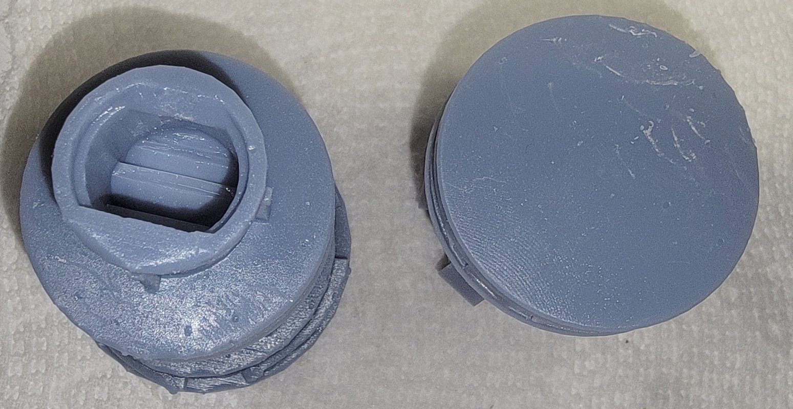
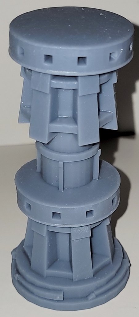
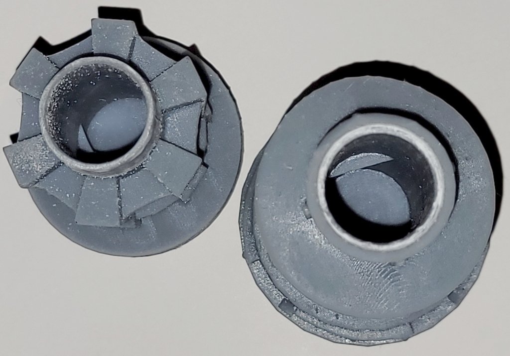
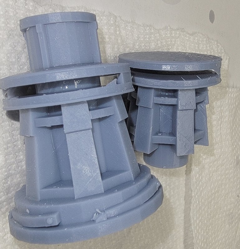
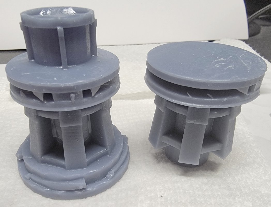
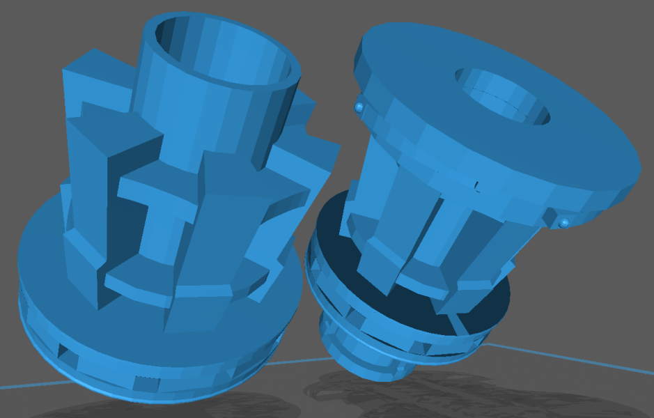
I figured I was done until the model was far enough along to merit adjusting and printing this thing, but I had a nagging feeling I needed to test print it rather than wait. Always trust your gut, I guess... The first thing I noticed was the boxes that formed the sockets for the capstan bars hardly printed at all. Both disks should have printed solid with square holes in it, so I'll probably need to rework it to figure out why they didn't. Note: I yanked off the supports, gave the parts a quick wash, and cured them quickly, so they don't look a good as they could even with their flaws The post connecting both capstans together is supposed to be a tube, and came out that way on the upper capstan, but, for some reason didn't on the lower one. The bottom closed-up except for a small gash, and inside it printed what look like vanes. The band at the top of the lower capstan which forms a socket for the upper to fit into, tried to fill in. In the model this part didn't have faces on it's inner surfaces, which is a sure-fire way to give the slicer a fit trying to interpret it. So it's "back-to-the-drawing-board"

- 97 replies
-
- 3
-
-
- macedonian
- frigate
- (and 2 more)
-
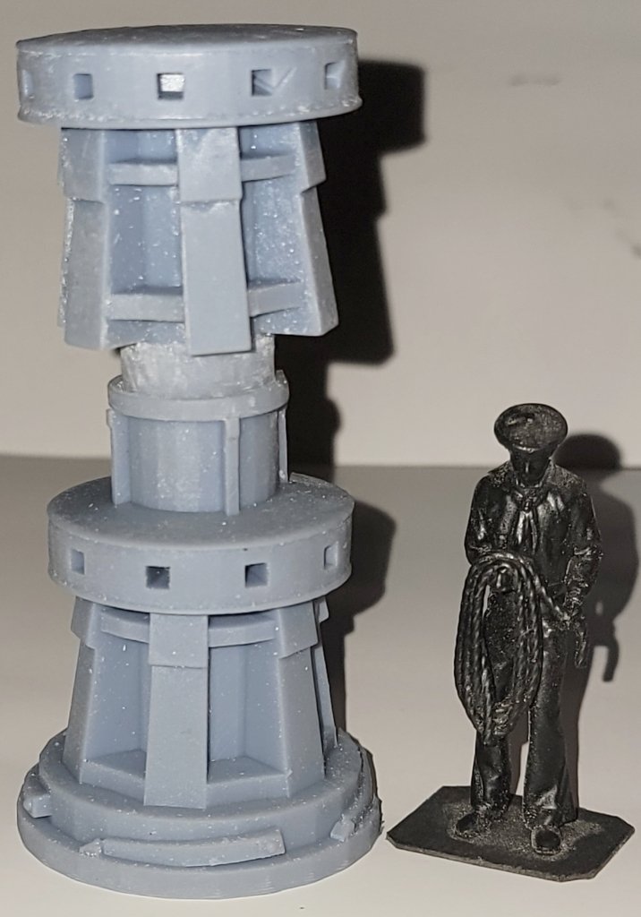
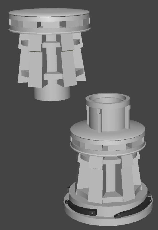
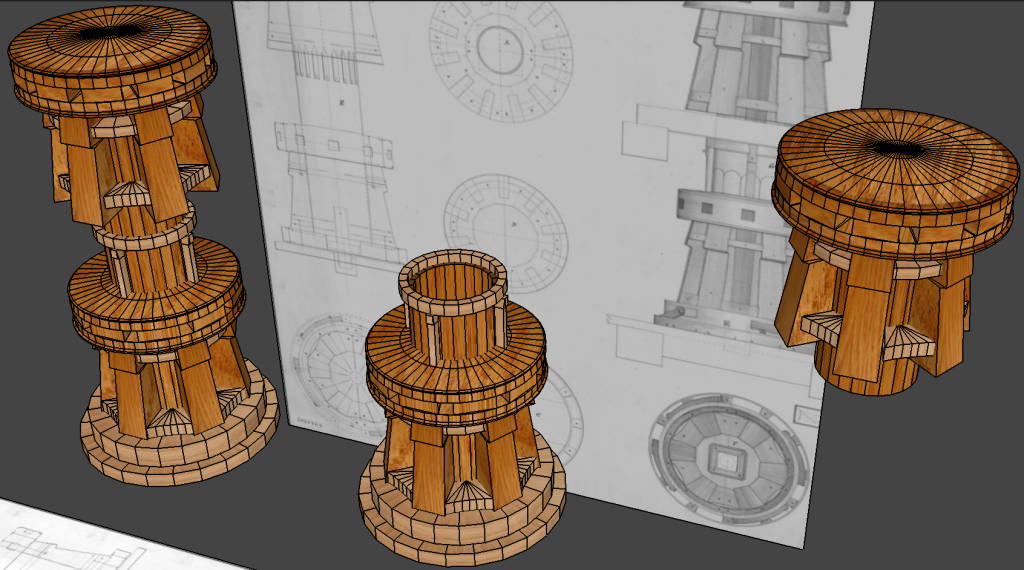
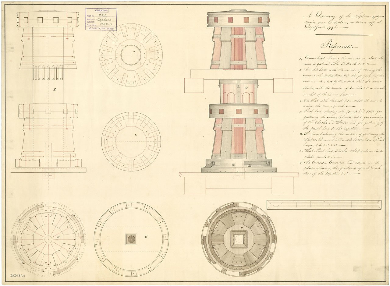
The gun models done, I moved on to the capstan. I based my model on a drawing from NMM of the Neptune's capstan "taken off at Deptford Yard, 1796" The drawing has an actual scale on it, rather than "1 inch = 5 foot." or some thing equally useless when you're working from digital scans. I'm working in Anim8or again, and had the bulk of the model done in a couple of hours. The spar-deck capstan is separate from the gun-deck one to make it easier to install in the model. I made the pillar hollow to save on resin and facilitate curing, so it doesn't crack over time. I breaks at the band above the lower capstan, and the bit that extrudes below the upper one will need to have it's length adjusted to fit what the model actually turns out to be. I simplified some items, like the pawls and stops, and the whole model's basically non-functional, 'cause I don't need it to be functional.

- 97 replies
-
- 4
-
-
- macedonian
- frigate
- (and 2 more)
-
Assuming you're working in 1:64 scale normal sewing thread should be fine, though I suggest polyester over cotton. Both Pride I & II's shrouds were wire rope and the seizings were also wire, though most eyes were spliced. Neither boat was truly "authentic."
- 1 reply
-
- 2
-
-
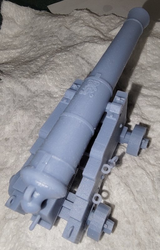
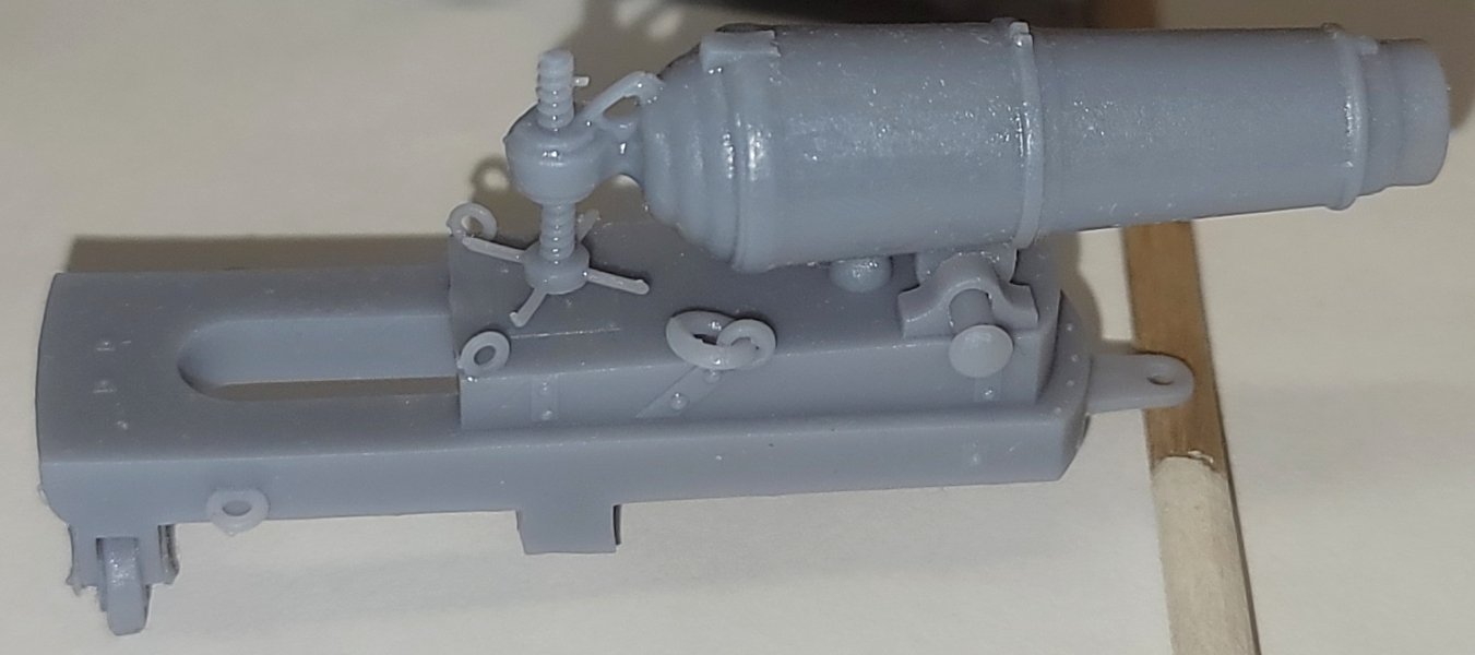
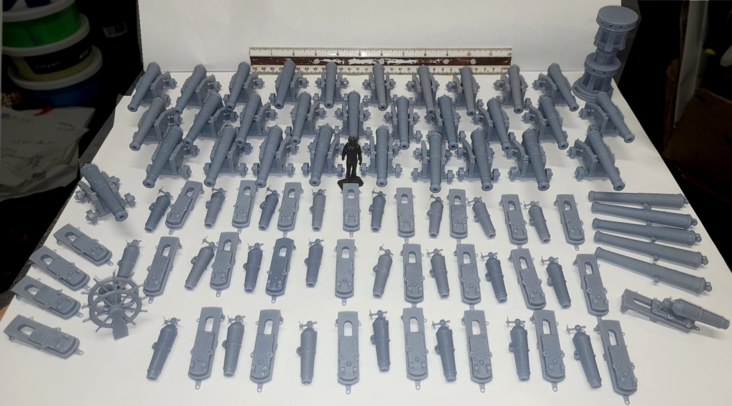
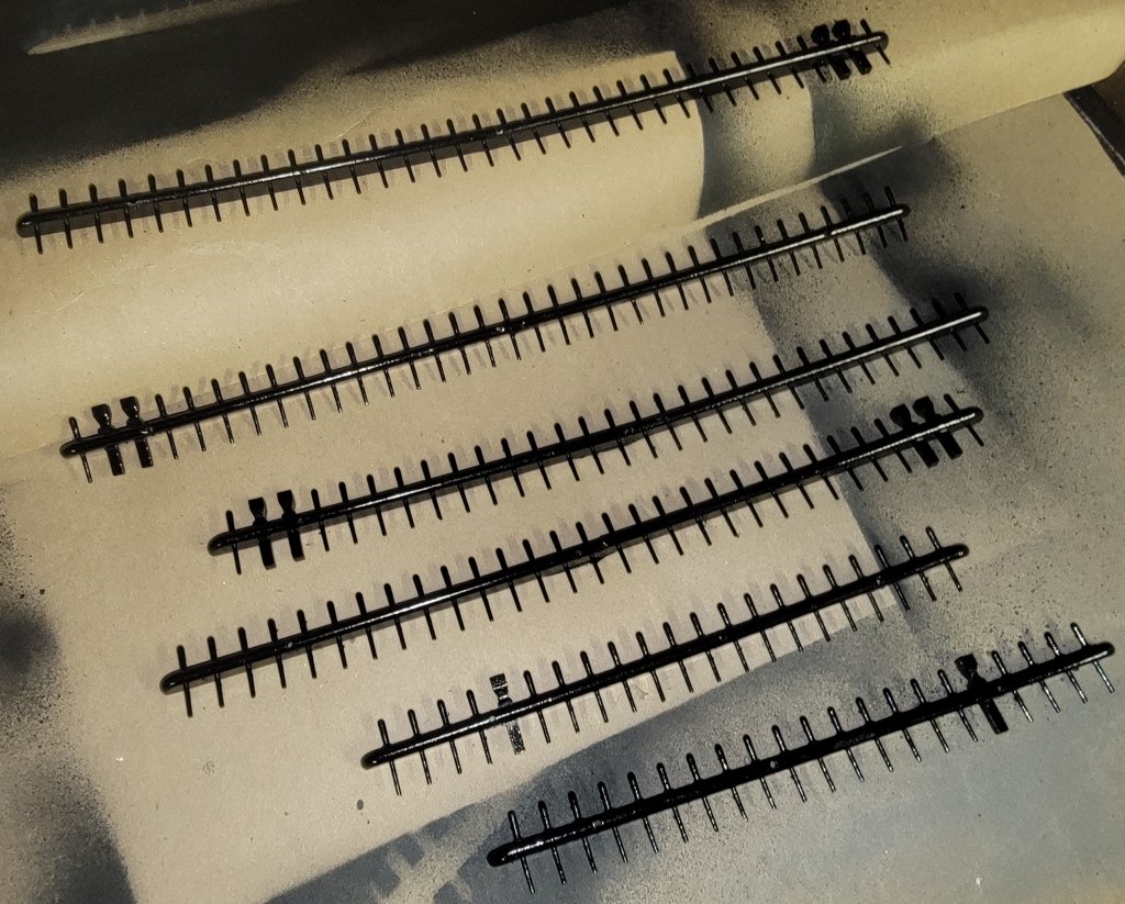
Still trying to figure out blender so i can do all the curly decorations on Constellation's head and Macedonian's stern and not doing very well with the learning curve, so after shoveling some snow today, I fell back on something I know how to do, guns. I had these basically modeled for a while now and was just adding details; eyebolts, rings, etc; but I rebuilt the carronade slide completely from scratch. For Macedonian, I'll need 22 carronades and 28 18's and maybe 2 more for chasers. Besides various drawings; I used images of the 18's on board Unicorn and the carronades on Trincomalee as general guides. The files for both are available on Thingiverse I've started printing them, though it's taken some fidgeting to get them to come out right, mostly in how they are angled and supported. I'm a bit up-in-the air about the color of the carriages/slides. On Victory their all a buff color, Trincomolee they're black, on Unicorn they're unpainted. So what color should I paint them for a frigate in 1812? Test prints are done, time to go into full production


- 97 replies
-
- 3
-
-
- macedonian
- frigate
- (and 2 more)
-
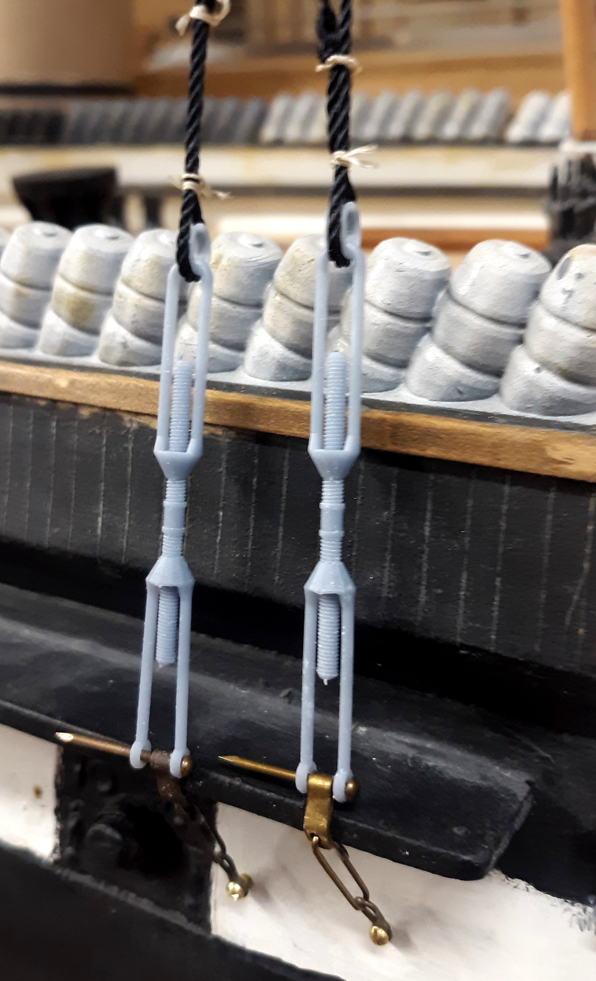
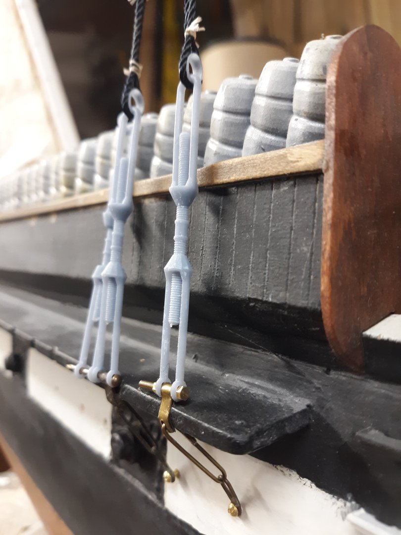
Most of the lines made-off to these pins will be static and basically "for show,' they won't be under much stress. I'm using a resin meant to be stronger than the stuff people use to print D&D porn figures. The real test will be the rigging screws

- 553 replies
-
- 4
-
-

-
- sloop of war
- constellation
- (and 3 more)
-
Does anyone know what this rigging is called?
JerryTodd replied to RobMann79's topic in Masting, rigging and sails
If your model is post 1800ish - it mostly likely didn't have this cat's cradle on it. -
Hello from the Chesapeake Bay area
JerryTodd replied to SaltyScot's topic in New member Introductions
Welcome from near Annapolis -
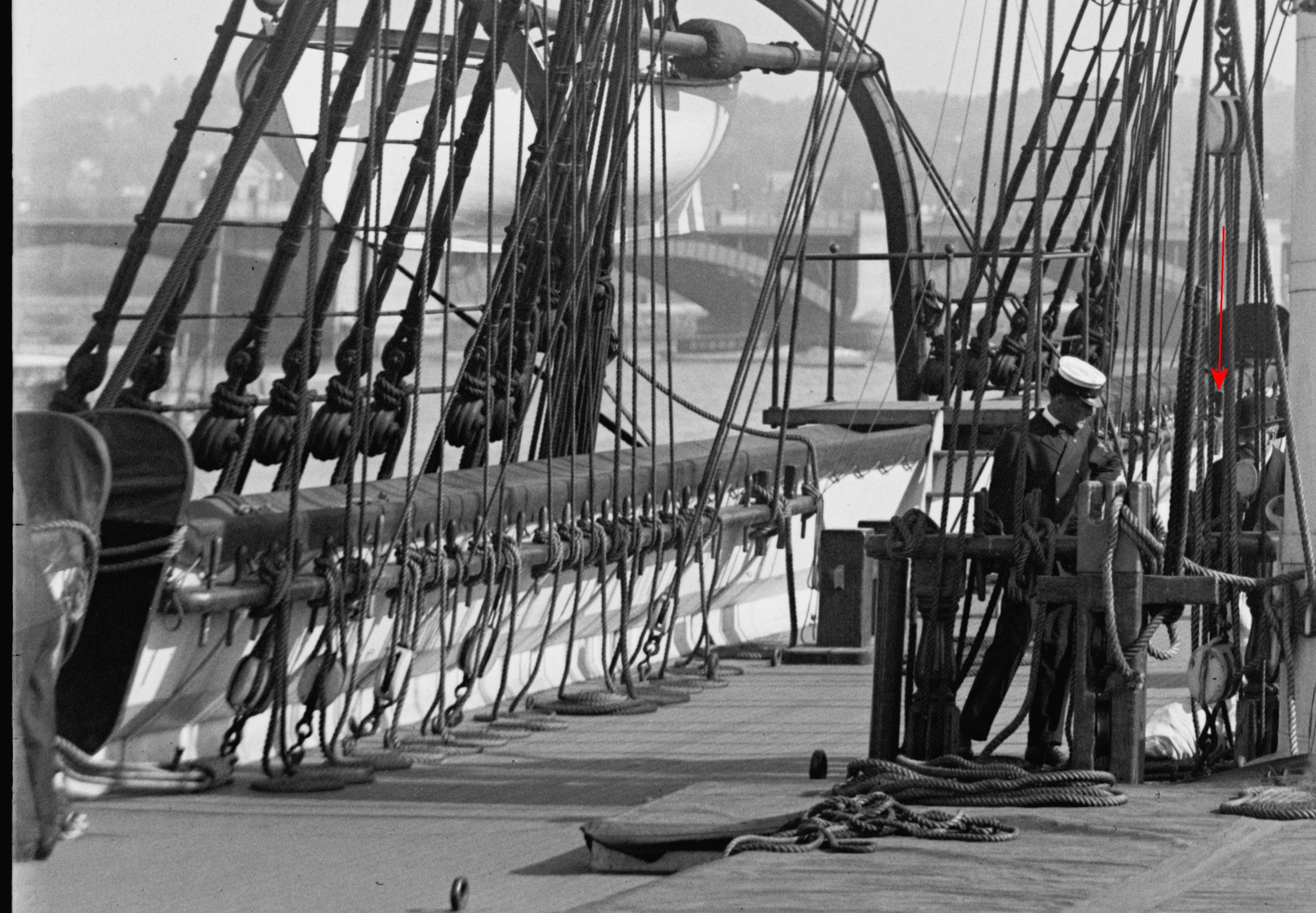
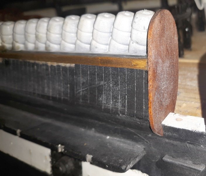
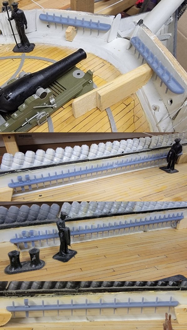
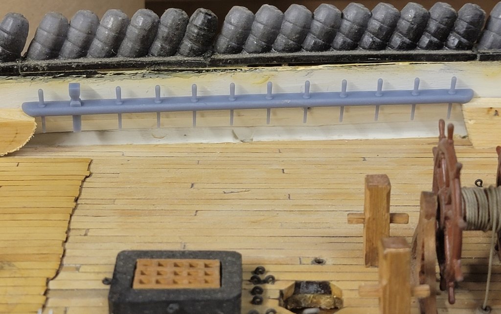
While looking for other possible pin-rails to make, noticed the aft pin-rails also had one of those big mallet pins, and also had more pins closer together than I had modeled. Follow the red arrow in this portion of an 1890s photo So, I fixed the 3D model and printed it, again The mounting holes were drilled and the rails primed, then painted. By the time they could be handled, it had gotten cold again, so they haven't been installed. The bulwark needs fresh paint were the pin-rails go anyway, so it's waiting for another unseasonally warm day (above 50°f outside) so paint and glues will set, and fingers will function

- 553 replies
-
- 3
-
-
- sloop of war
- constellation
- (and 3 more)