
JerryTodd
-
Posts
879 -
Joined
-
Last visited
Content Type
Profiles
Forums
Gallery
Events
Everything posted by JerryTodd
-
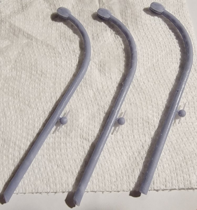
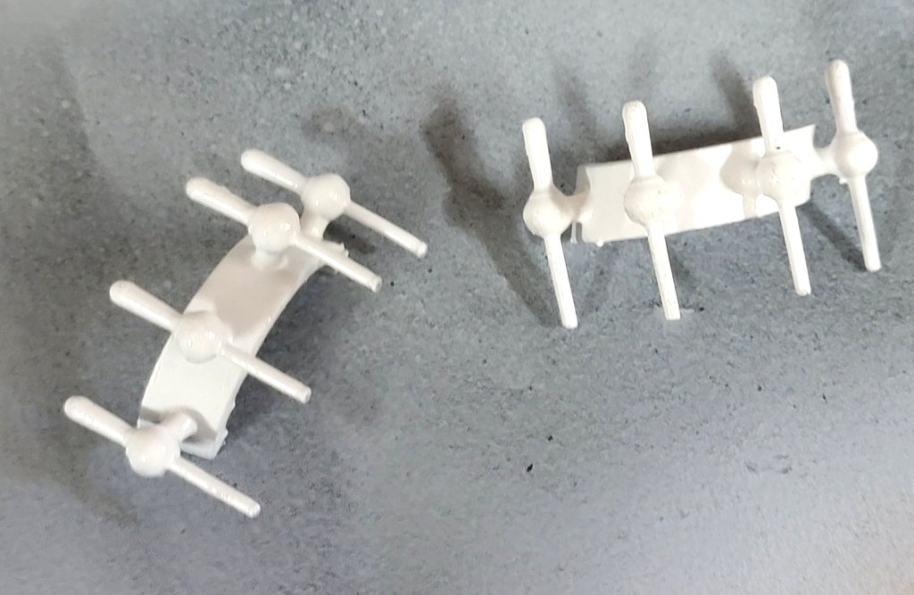
 Thank you Ban, They are very rough, I just slapped a double block on a bent pole. I think that knob at the end may be an acorn? I am working on a more rounded block for it that looks like it belongs.
 -
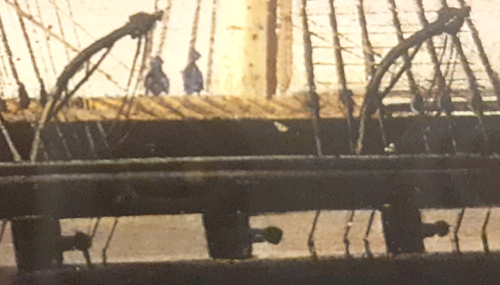
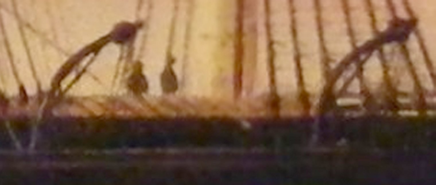
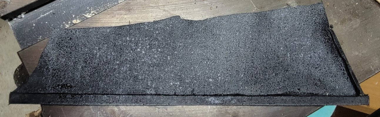
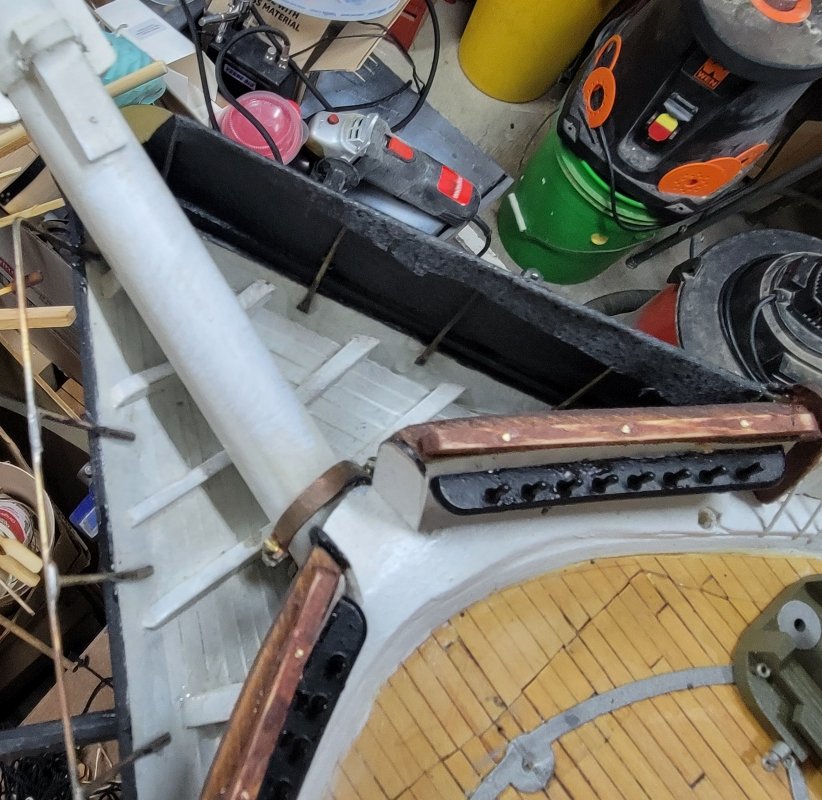
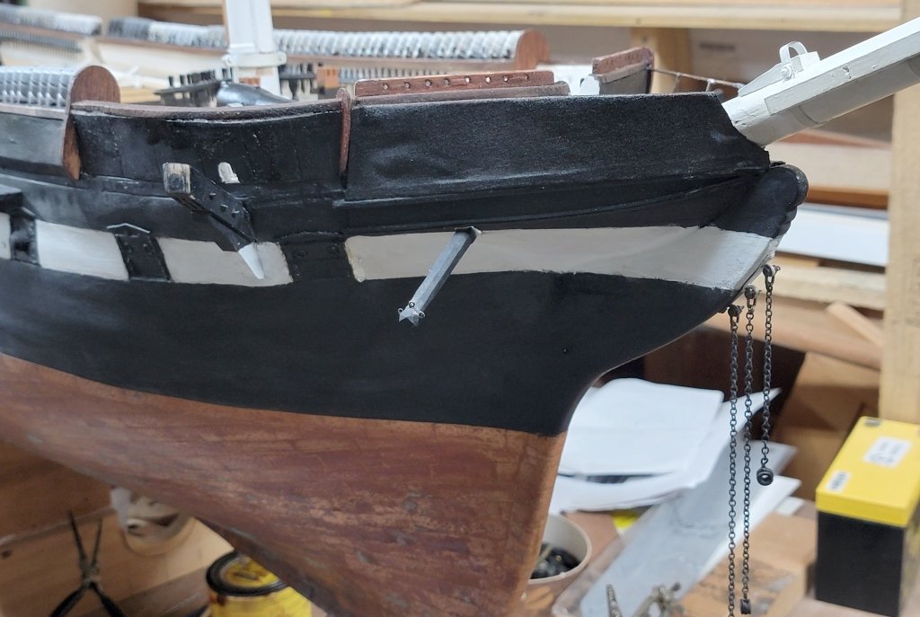
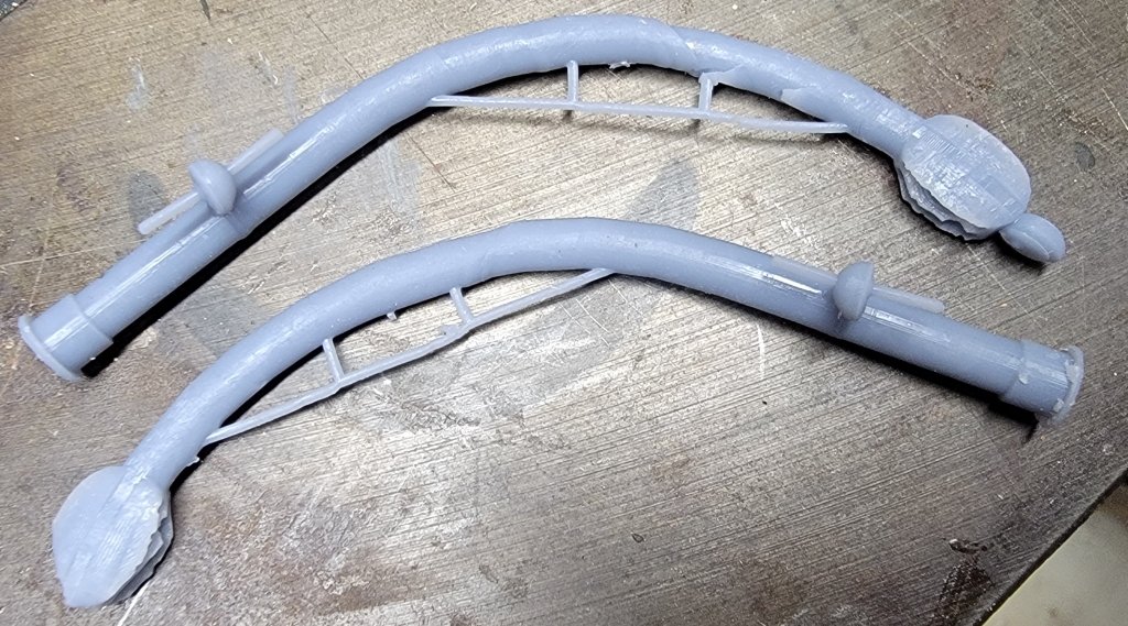
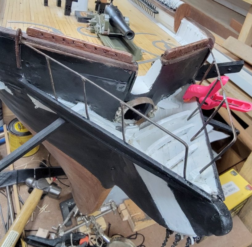
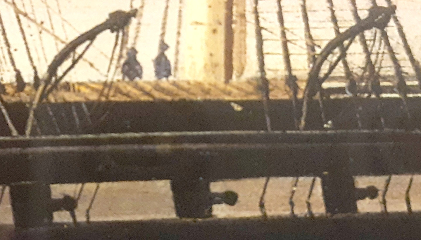
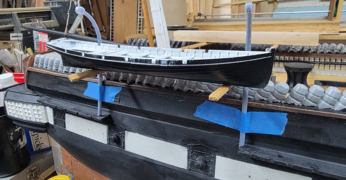
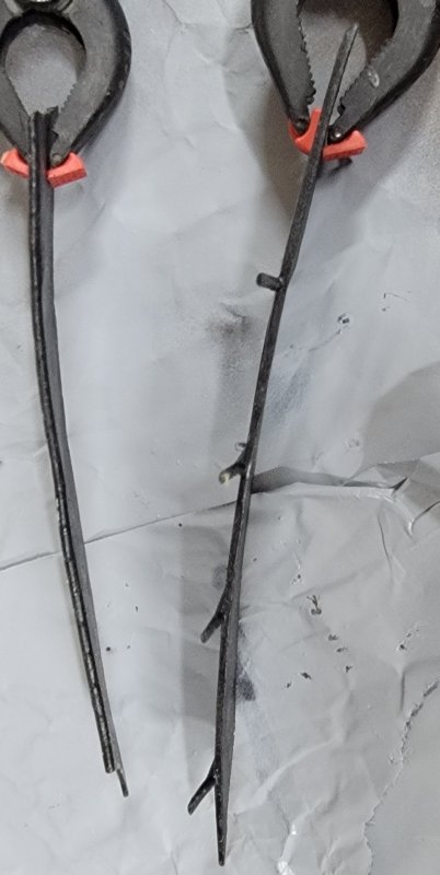
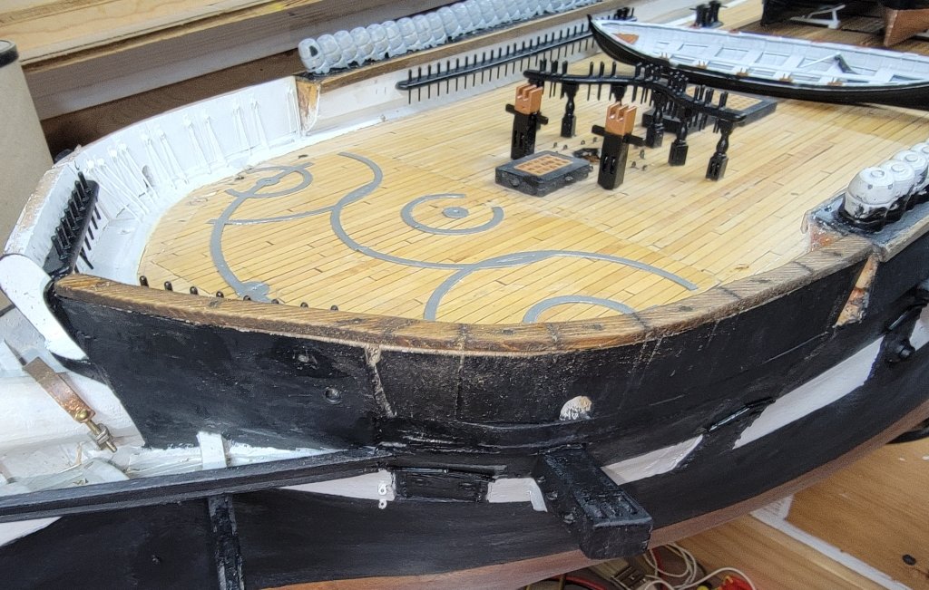
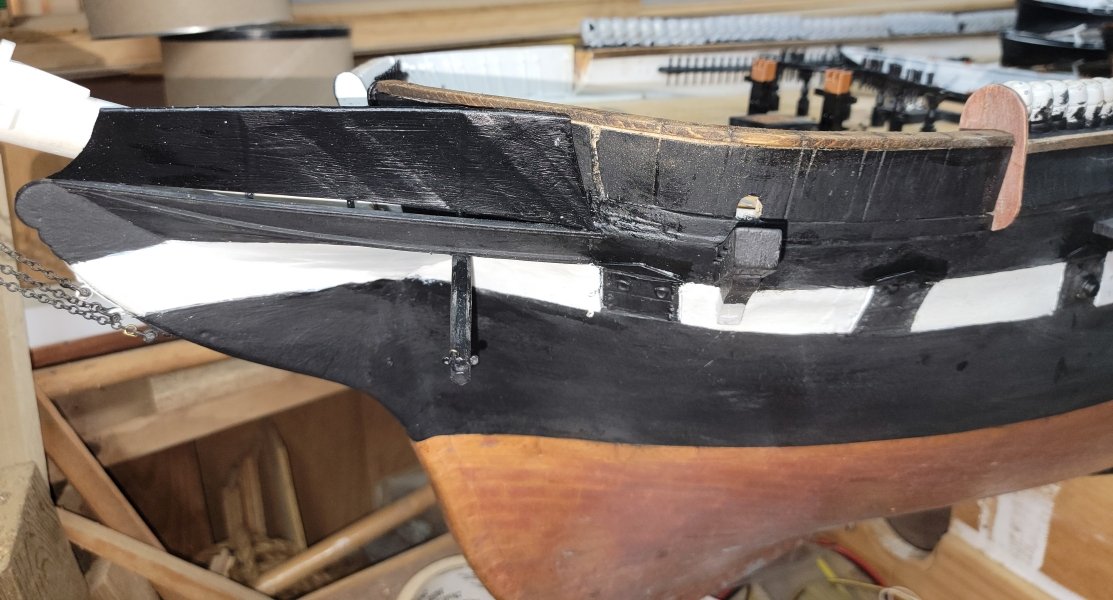
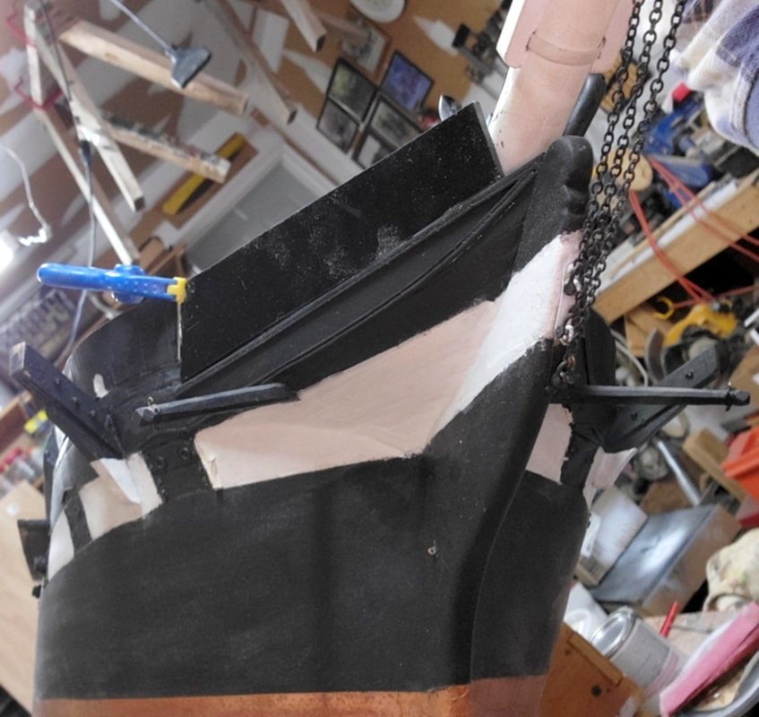
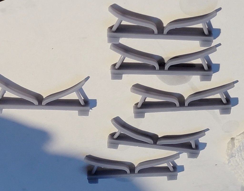
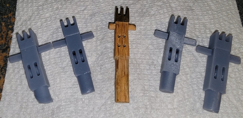
I bent and soldered some 1/16" brass rod in a jig made of scraps to make frames for the spray-screens. The jig didn't fair well, but the frames came out fine. I flattened the legs to give a better glue surface, and bent them to the needed angle. They got installed in the head with CA, and then I a coat of 5-minute epoxy over them. I cut some gray Supplex from the 2 yards I have for Macedonian's sails; glued and hemmed in strips of wood for the bottom, and the aft end, using the 3D printed version to get the angle and length right. The bottom was CAed to the head-rail and the aft end to the hull. The loose portion was pulled over the frame and CAed in place. Once I get the other side to this point, I'll lace them to the frame with Dacron sail thread and brush on another coat of paint. In the painting I'm basing the model on, of the ship in Naples in 1856 by Tamoso de Simone, the ship's at anchor with her boats away, so this is how her quarter-boat davits are show. I have yet to find a painting, a photo, or a model that depicts this style of davit. My previous try was nothing like this, so I tried again and wound up with this: These didn't print well, two of them actually failed completely, but there's enough here to see if they look right. I'm satisfied they look like the silhouettes in the painting, and that's about it. There's no tackle going into the rig for raising or lowering them. I assume they rotate in sockets on their bases and probably have some sort of brace attached to the bulwark, cause just sitting on the channel isn't going to hold them up; also I can't see in the painting that they extend below the channel to be supported by the hull. Fortunately, davits will be about the last thing that gets installed, so I have time to ponder this some more before then.
- 553 replies
-
- 4
-

-
- sloop of war
- constellation
- (and 3 more)
-
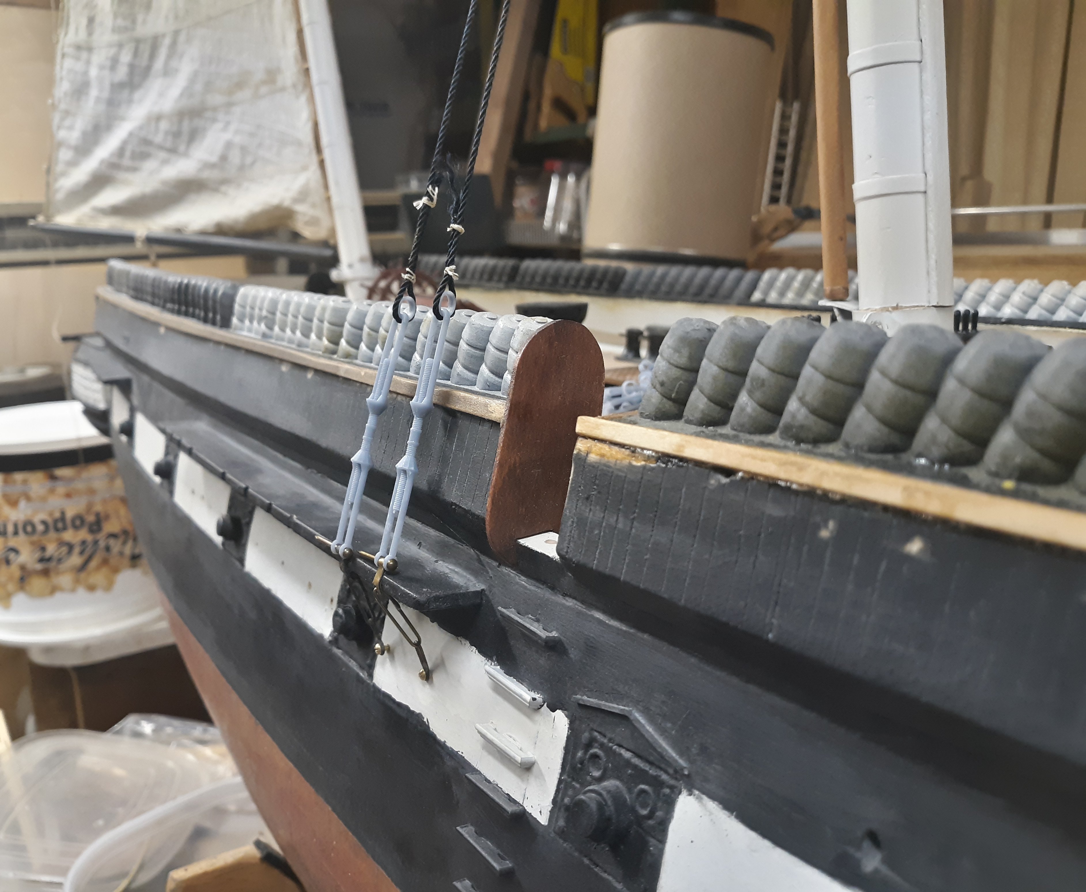
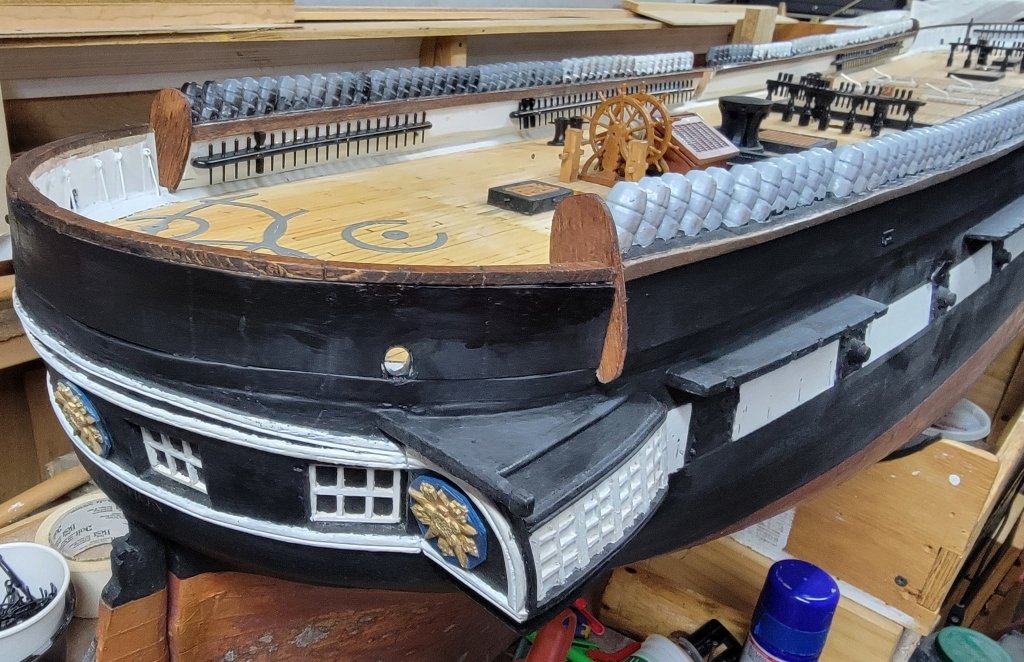
I made all new, thicker, end-boards and installed them, which required opening up the space so they'd fit. Then I added a fairlead log at the bows. Looking though photos to see what this looked like, I noticed the ship now doesn't even have pin-rails up here. Looking at installing the spray-screens up at the head, the 3D printed ones, because of their thinness, curled. I think they're likely to break being forced flat and installed under tension like that, so I think I'm going to brush up my soldering and make a metal frame covered with painted cloth, basically they way the real one was done. Though they'll probably be one of the last things to get installed, but I've been trying to figure out the quarter davits for some time. What I can find images of are not what I see in the portrait, so I popped out this little experiment. These aren't the final product, and the more I look at them, they aren't even close, so it's back to the drawing board.

- 553 replies
-
- 2
-
-
- sloop of war
- constellation
- (and 3 more)
-
Don't forget to paint her "pungy pink!"
-
FYI: The miter-cut "flying jib" (jib), where the panels meet at a 90° diagonally across the sail, did not come into use until the late 1860s. There may have been a "miter-band", or reinforcing cloth across the sail over the panels in line with the pull of the sheets, but the sail would have otherwise been cut the same as the "jib" (forestays'l) they show.
-
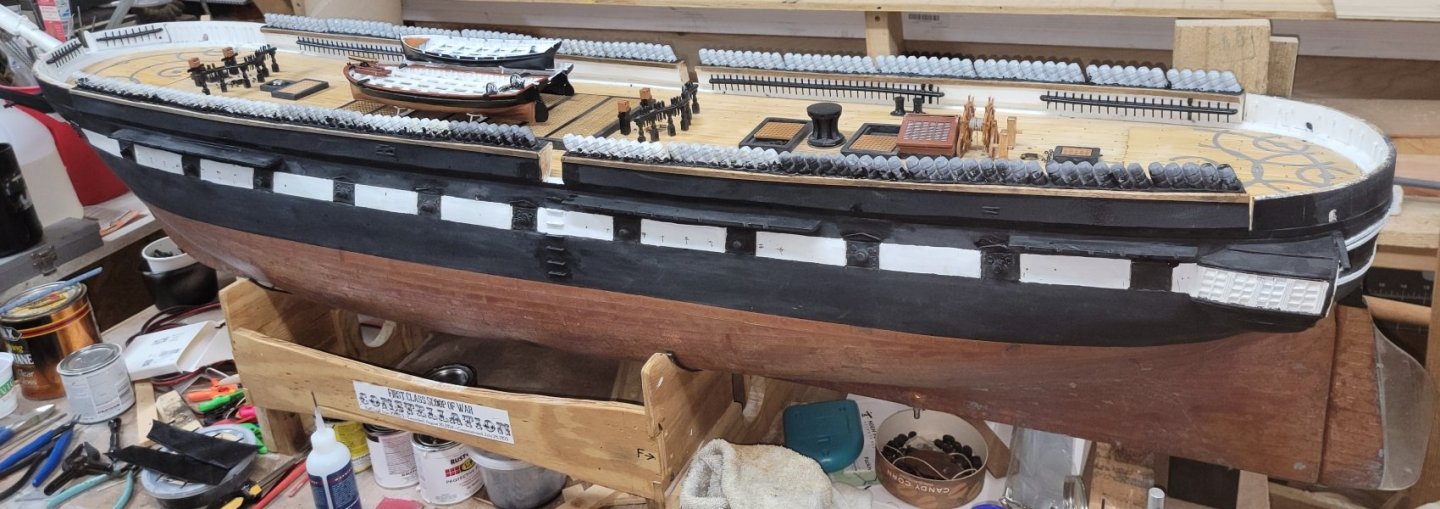
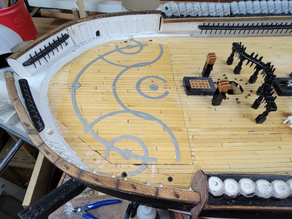
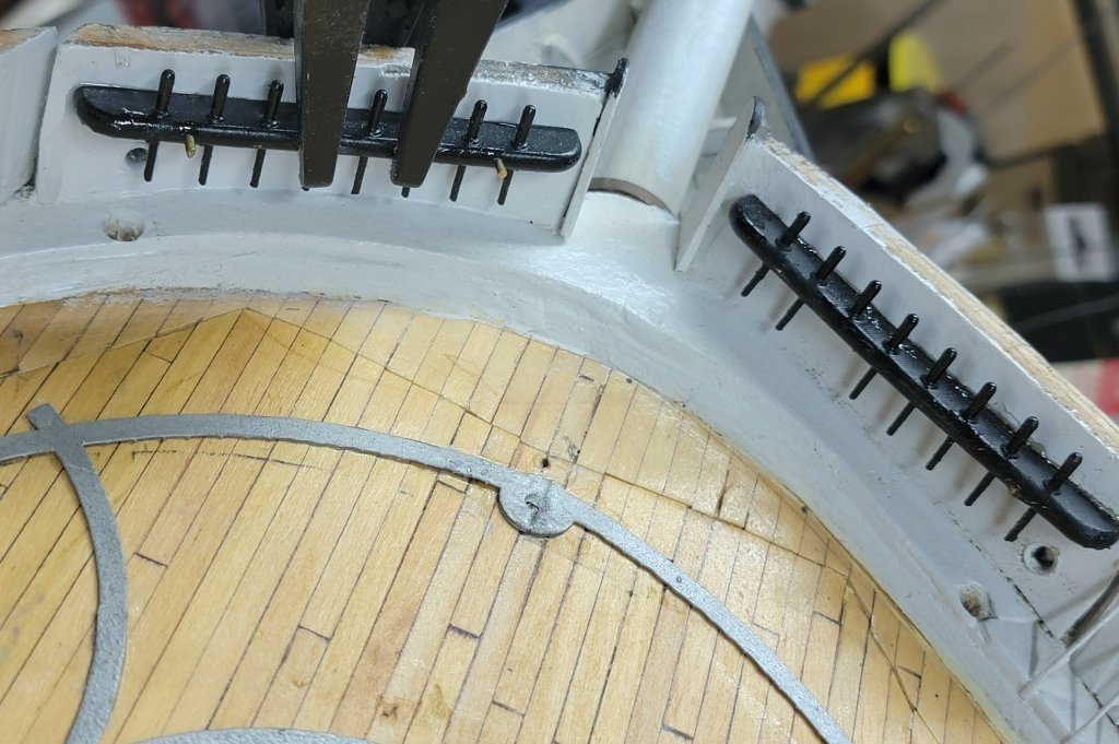
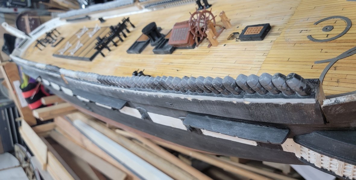
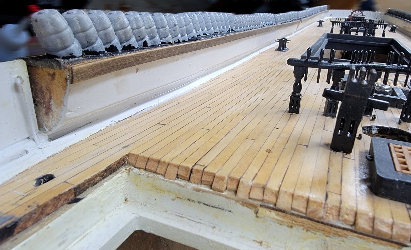
The port-side pin-rails got epoxied in place, and one of the outboard trim boards went on, the clamps were in the way of doing the aft one. Once the clamps were off, the trim piece went on. Then the cap-rail went on where the drop-panels are. I made a card template and cut the rail from some wood a friend left me after making a guitar. It was glued and pinned with round toothpicks. With the spray-rail and end-board sitting there, it almost looks done. The aft rail went on next, and then the forward, starboard side...


- 553 replies
-
- 3
-

-
-
- sloop of war
- constellation
- (and 3 more)
-
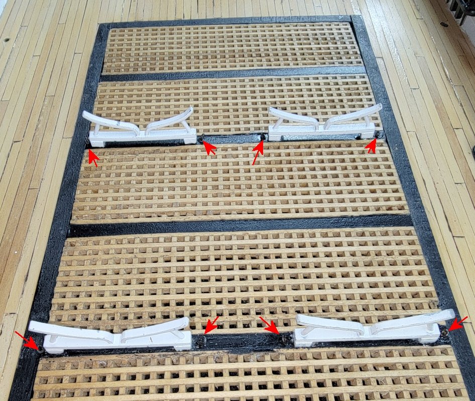
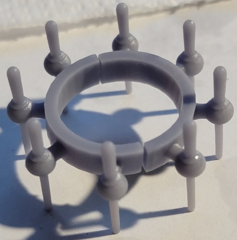
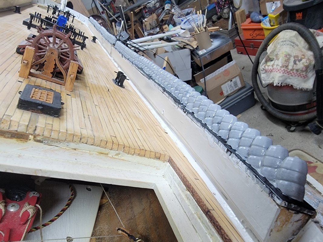
The spider-band got primed and painted; the other bow pin-rail was glued on; the trim-boards were installed on the inboard port-side; and the boat cradles were CAed to the hatch cover and eye-bolts installed for tying the boats down. Oh, and I made and printed a test-model of the spray screen for the head, it needed some adjustment and a little detailing so it'll look more like a tarpaulin than a bulkhead. Addendum: I put some twist into the model of the spray-screen (It's vertical aft and should flare out at the bowsprit). I added a curved bit at the forward end to curl under the bowsprit, as it appears in many images. Moved one of the stanchions to not interfere with the frames of the enclosed head in one spot, and tried to make it look more like fabric than flat planking. It seems my head construction isn't symmetrical (or warped slightly over the years) and has a little bow in the head rail on the port side. If I can't flex things enough to close the gap, I'll alter the model and print another one to fit that side.

- 553 replies
-
- 2
-
-
- sloop of war
- constellation
- (and 3 more)
-
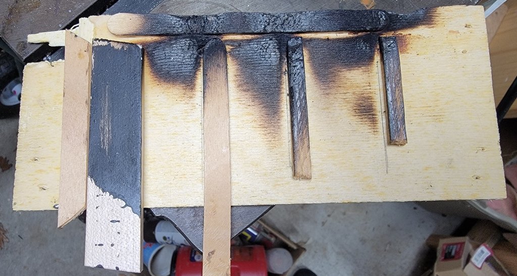
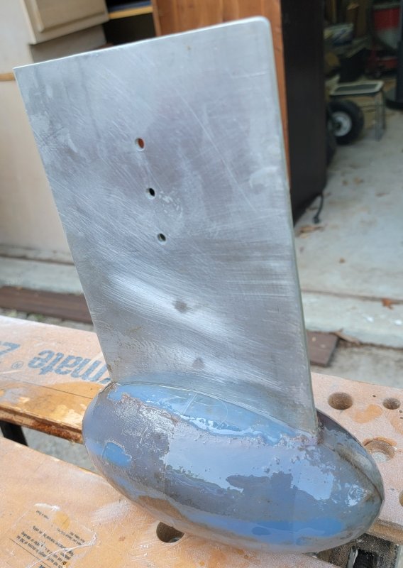
The bulb got sanded and coated in epoxy today. When that had set, it got sanded and coated with epoxy again, then sanded and primed - twice, and finally sanded and painted Moss Green - twice.


- 79 replies
-
- 1
-
-
- pride of baltimore
- privateer
- (and 3 more)
-
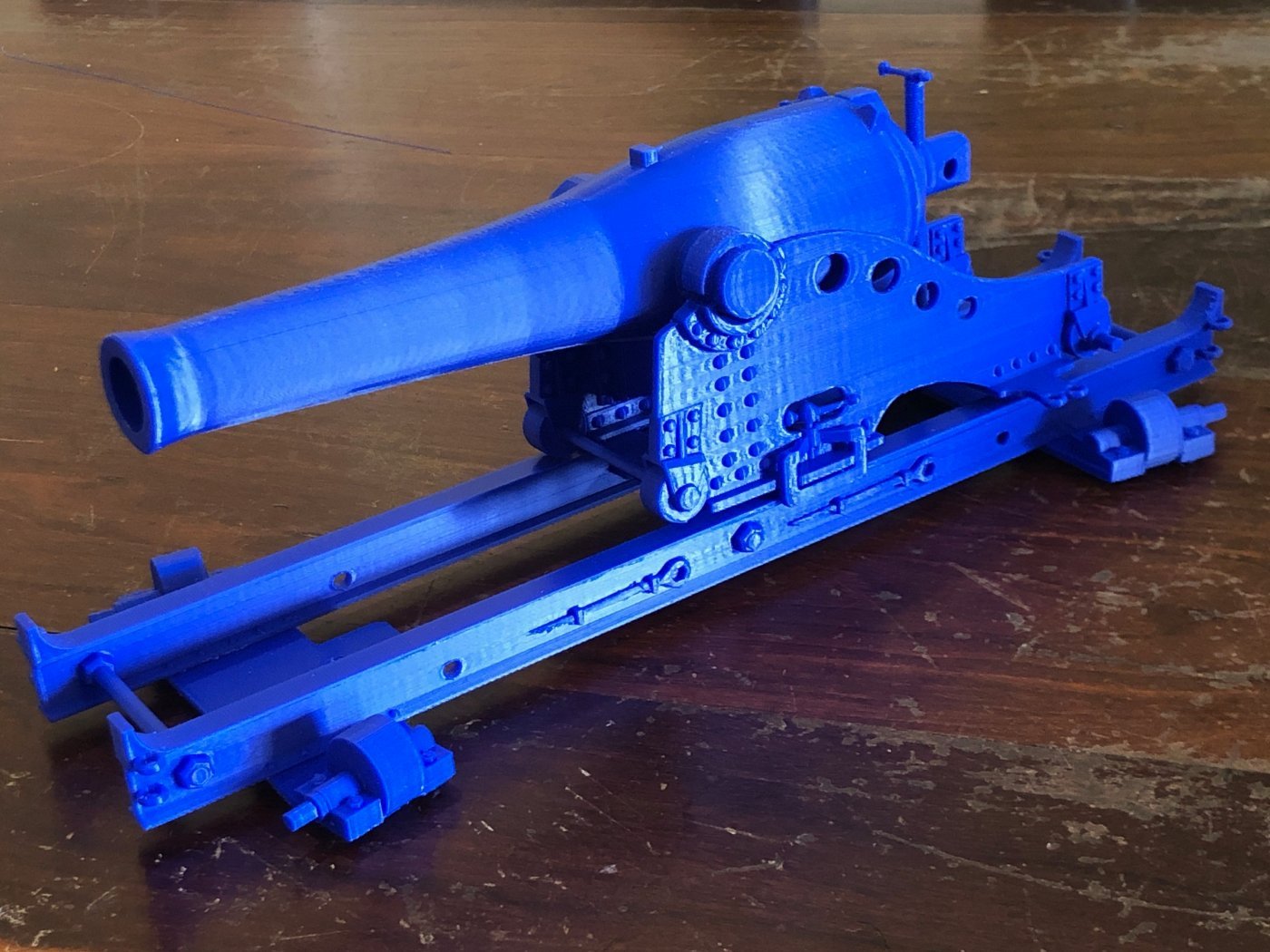
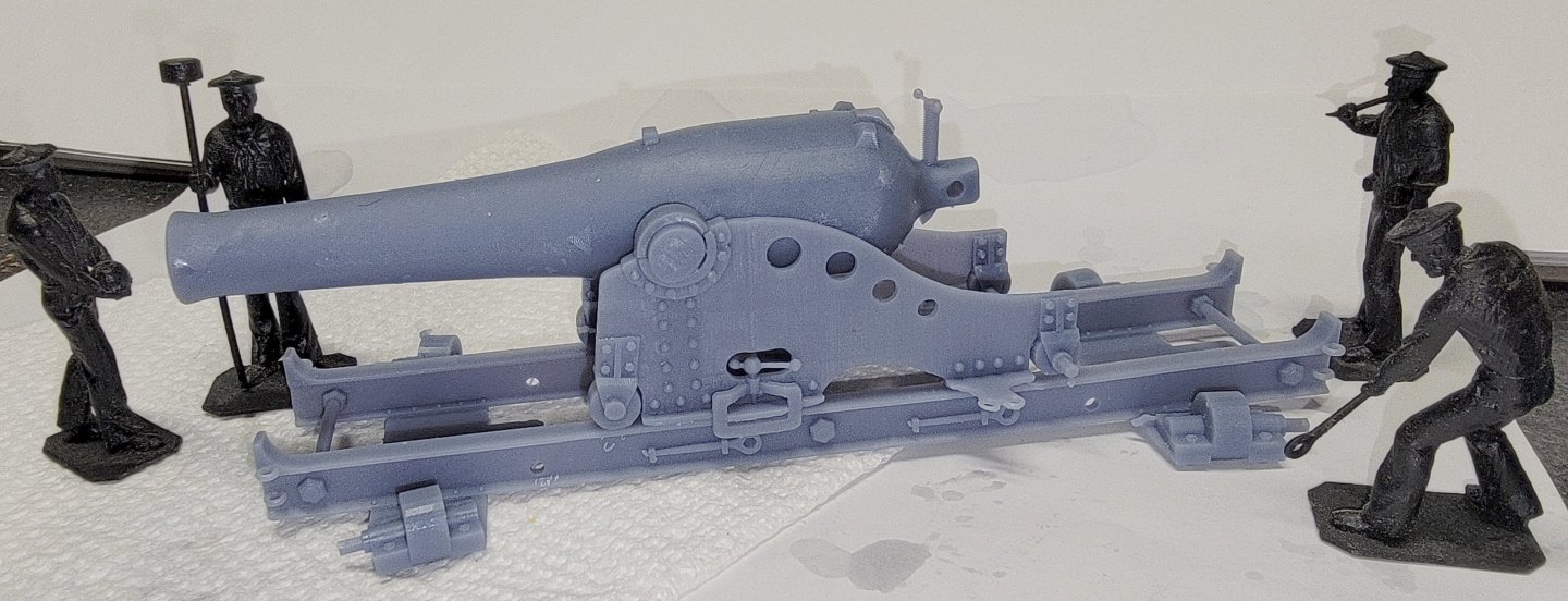
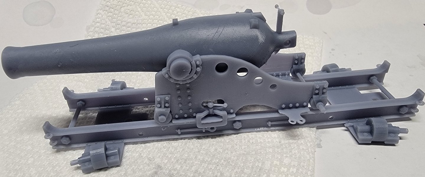
3D Naval Guns 1850s ~ 1870s
JerryTodd replied to JerryTodd's topic in CAD and 3D Modelling/Drafting Plans with Software
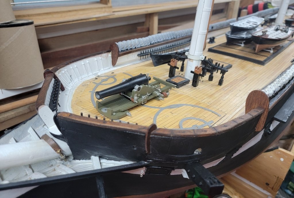
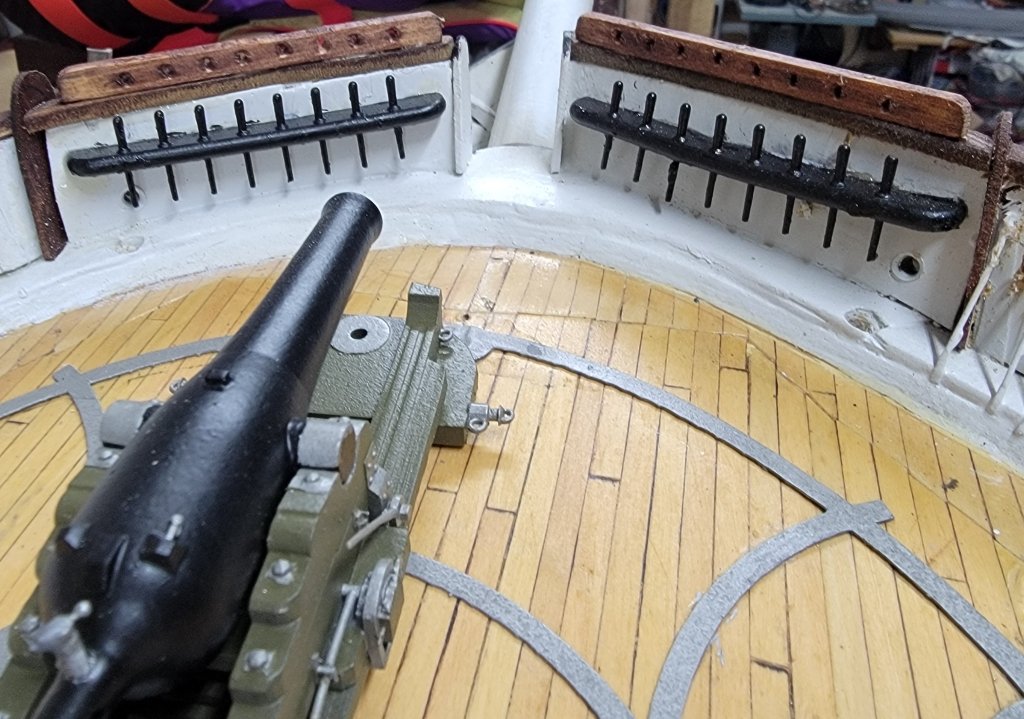
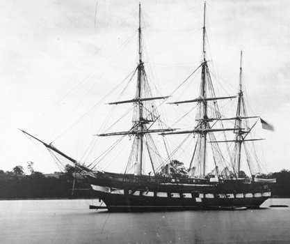
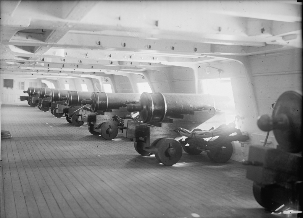
I'm not sure what color the carriages should be. They were olive up till the Civil War, then usually black (with some exceptions). Deck furniture, including gun carriages, got painted white after the war, and I assume Constellation would have followed that trend. As a training ship in the 1870's, she also had some IX Dahlgrens, but I'm trying to find out if they were on wooden or iron carriages. I'll probably print and iron carriage version anyway. I haven't found any images of her gun deck during the 1870's, the only image during this time I know of is a view of her at anchor near Annapolis in 1879. By the 1900's she borrowed guns from Constitution so she could play frigate in Baltimore for the anniversary of the Bombardment of Fort McHenry. (I'll be making these guns too, eventually)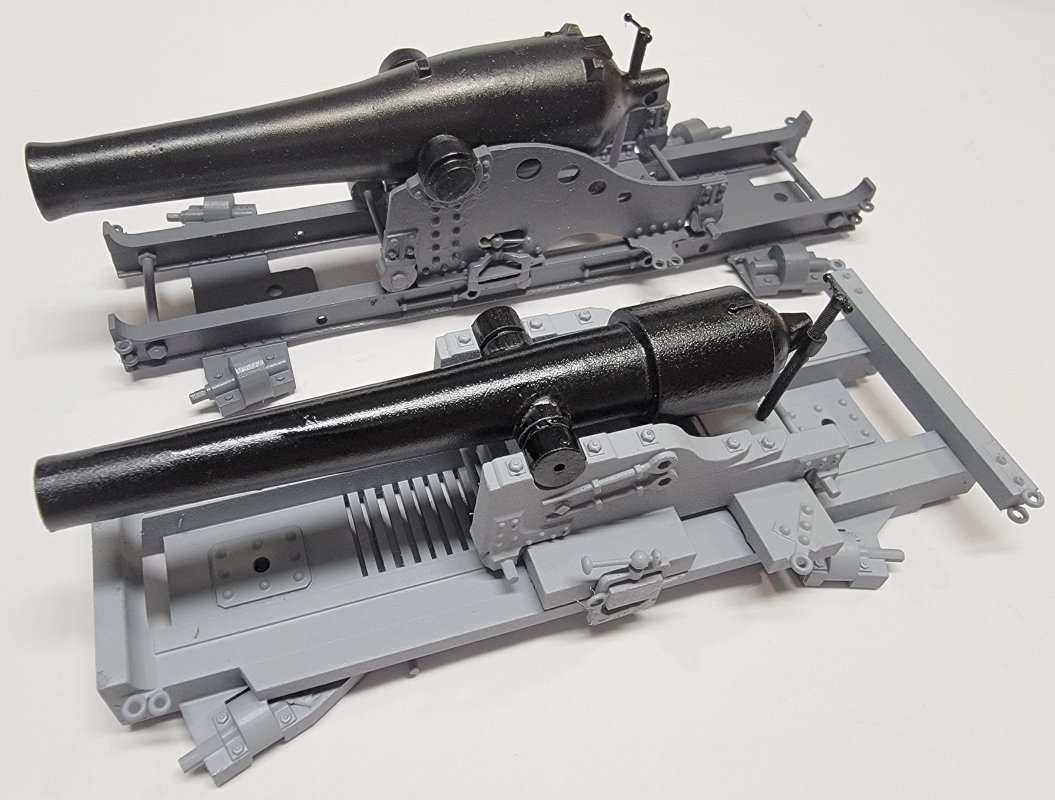
-
It's those sometimes year(s) long lapses in work that really slow things down.
- 553 replies
-
- 1
-
-
- sloop of war
- constellation
- (and 3 more)
-
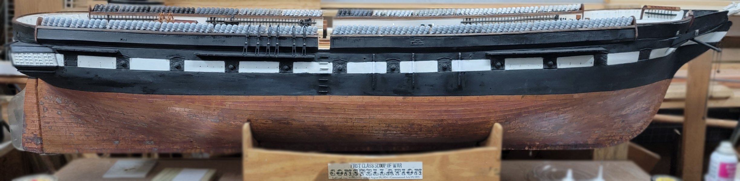
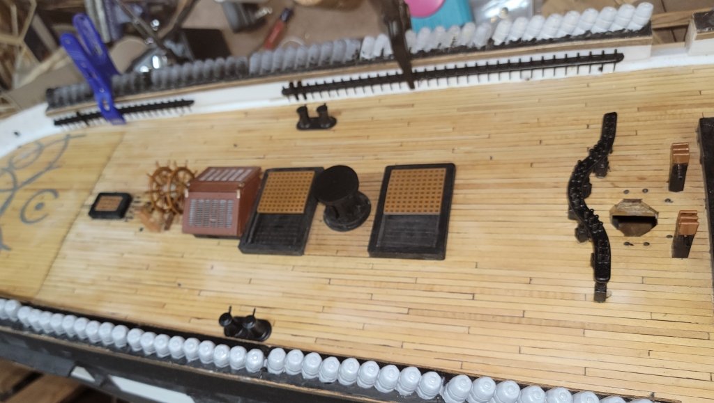
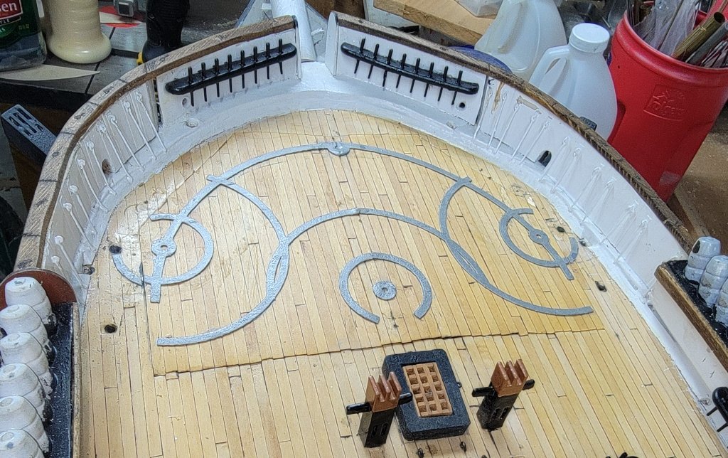
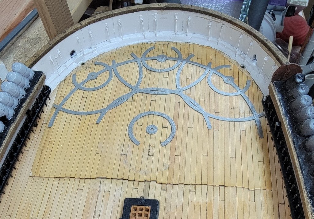
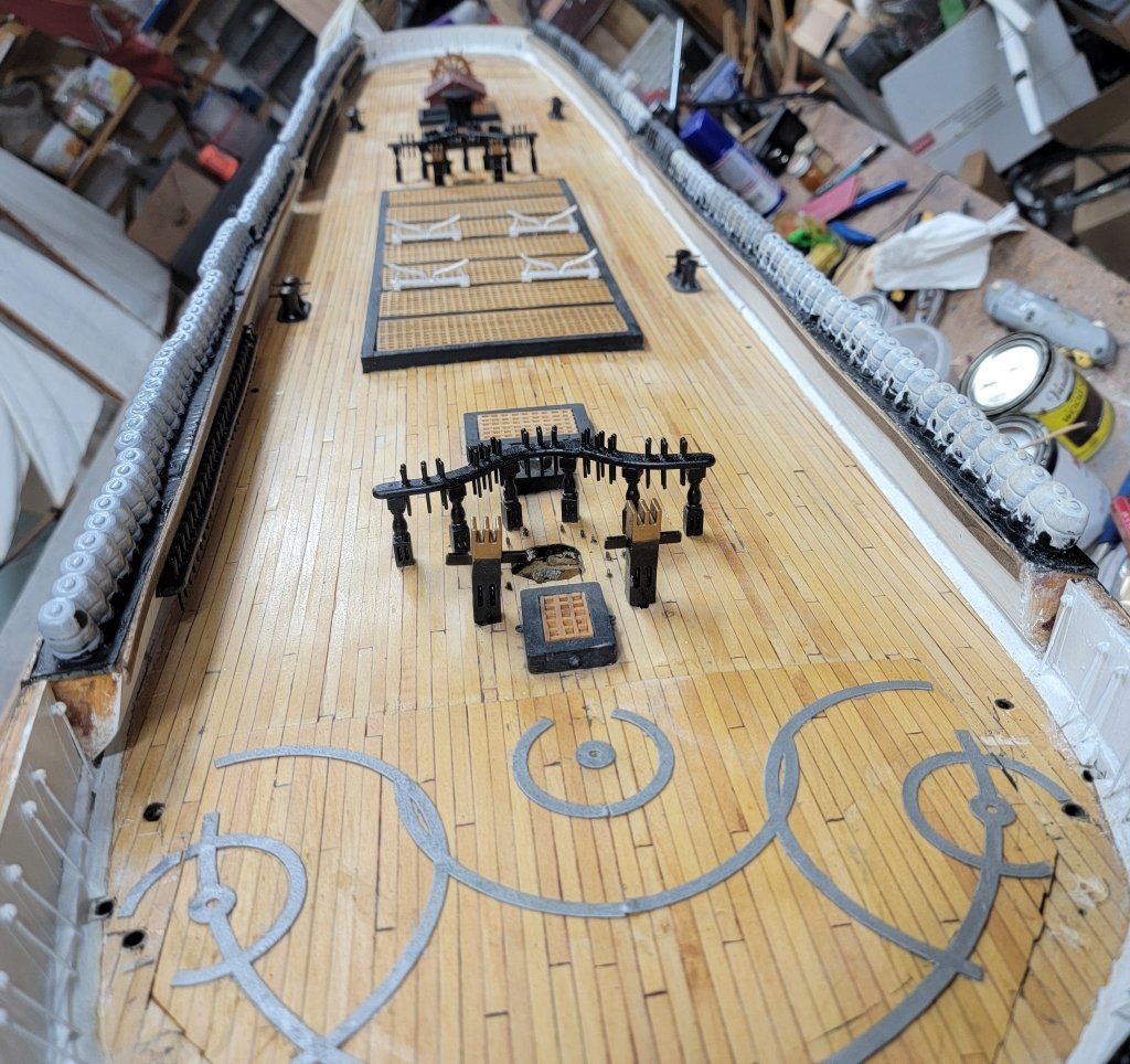
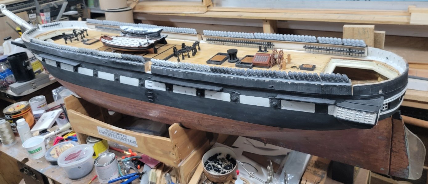
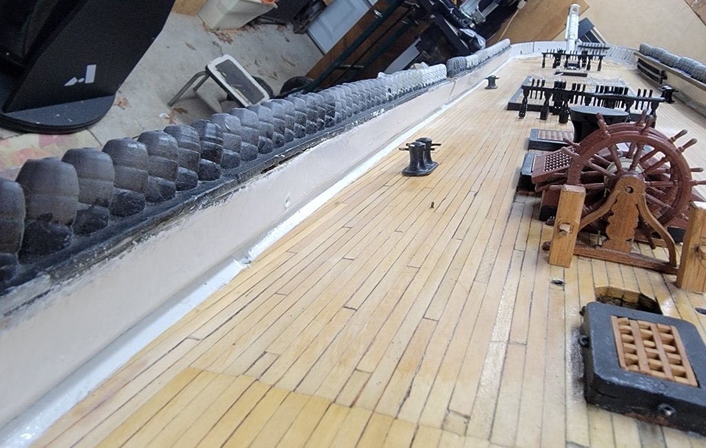
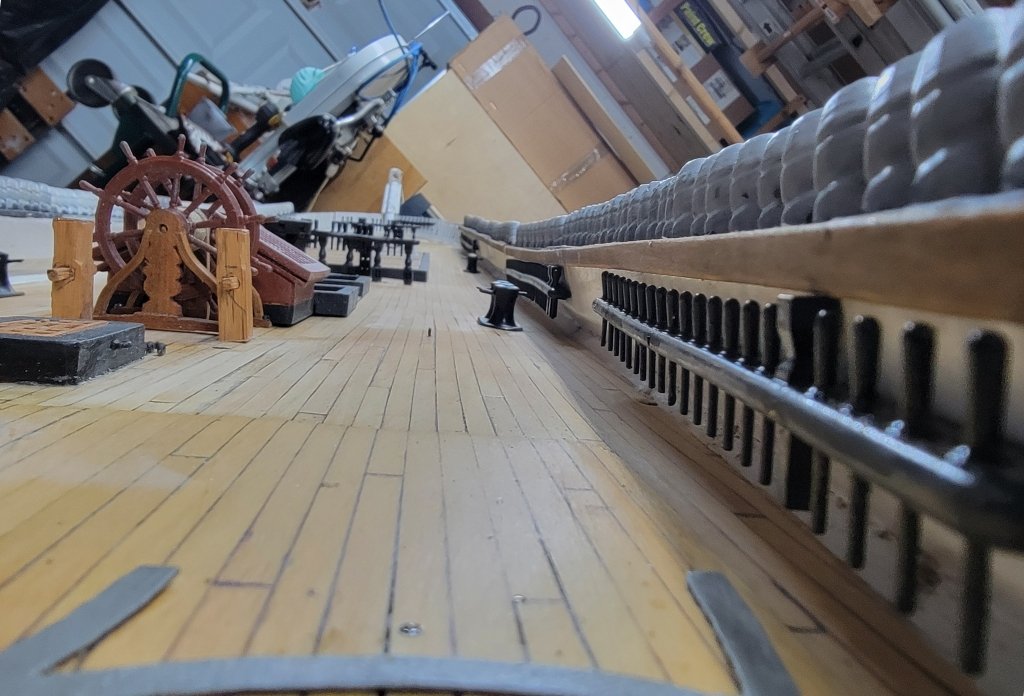
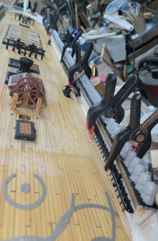
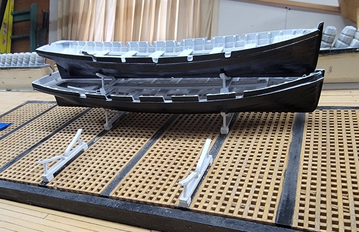
With the starboard pin-rails permanently glued and pinned in place, I ground the outboard port-side hammock trays flush with the bulwark. It didn't take much because I was more careful to set them that way when I glued them on; I basically beveled their edges to line up with the bulwarks' surface. I cleaned up the dust and painted the outboard side of the starboard hammocks then turned the hull around on the bench. The inboard side of the port hammocks were ground flush with the bulwark, cleaned up, and I painted the hammock trays and outboard side of the bulwarks black, and the inboard side of the bulwarks and waterways white. The basswood trim pieces will come next. (I get the camera angles can get confusing, but I try to leave a landmark, like the ship's wheel, visible to help orient things.) I glued the boat cradles temporarily to the main hatch with some PVA, but I bumped one and it flew off into oblivion. I'd been working on a model for mizzen spider-band, so when I printed that, I tossed another set of boat cradles in with it.
- 553 replies
-
- 3
-
-
- sloop of war
- constellation
- (and 3 more)
-
If not for the clamps, you wouldn't know the pin-rails got epoxied in today, or Pride got some work done too.
- 553 replies
-
- 1
-
-
- sloop of war
- constellation
- (and 3 more)
-
Well, it's not a pretty picture, but it does show progress, which is pretty in it's own way... Pride's ballast bulb got a coat of epoxy today. The epoxy was mixed with sawdust to thicken it, (I was also gluing in Constellation's pin-rails), but it still ran out of the gap I was trying to fill, and I had to spend a lot of time chasing it back up. The bulb's also wrapped in a portion of pantyhose, acting as glass cloth would, the idea being to strengthen it against possible impact. There's obviously gonna be some sanding to do, then it'll get some epoxy (sans sawdust) painted on to make it all nice and smooth with no gaps. Then it gets painted Moss Green like the bottom of the hull.

- 79 replies
-
- 2
-
-
- pride of baltimore
- privateer
- (and 3 more)
-
Topsail schooner sail plans and rigging
JerryTodd replied to Dr PR's topic in Masting, rigging and sails
Lynx is not a Baltimore Clipper, or even a "replica" of anything, she's just a schooner cosplaying as a privateer by an owner enamored with the first Pride of Baltimore, which is why she wear Pride's paint scheme. -
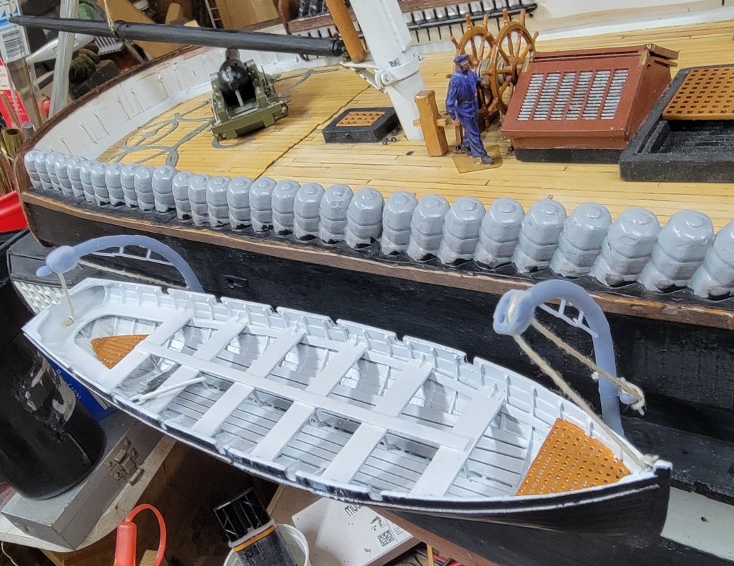
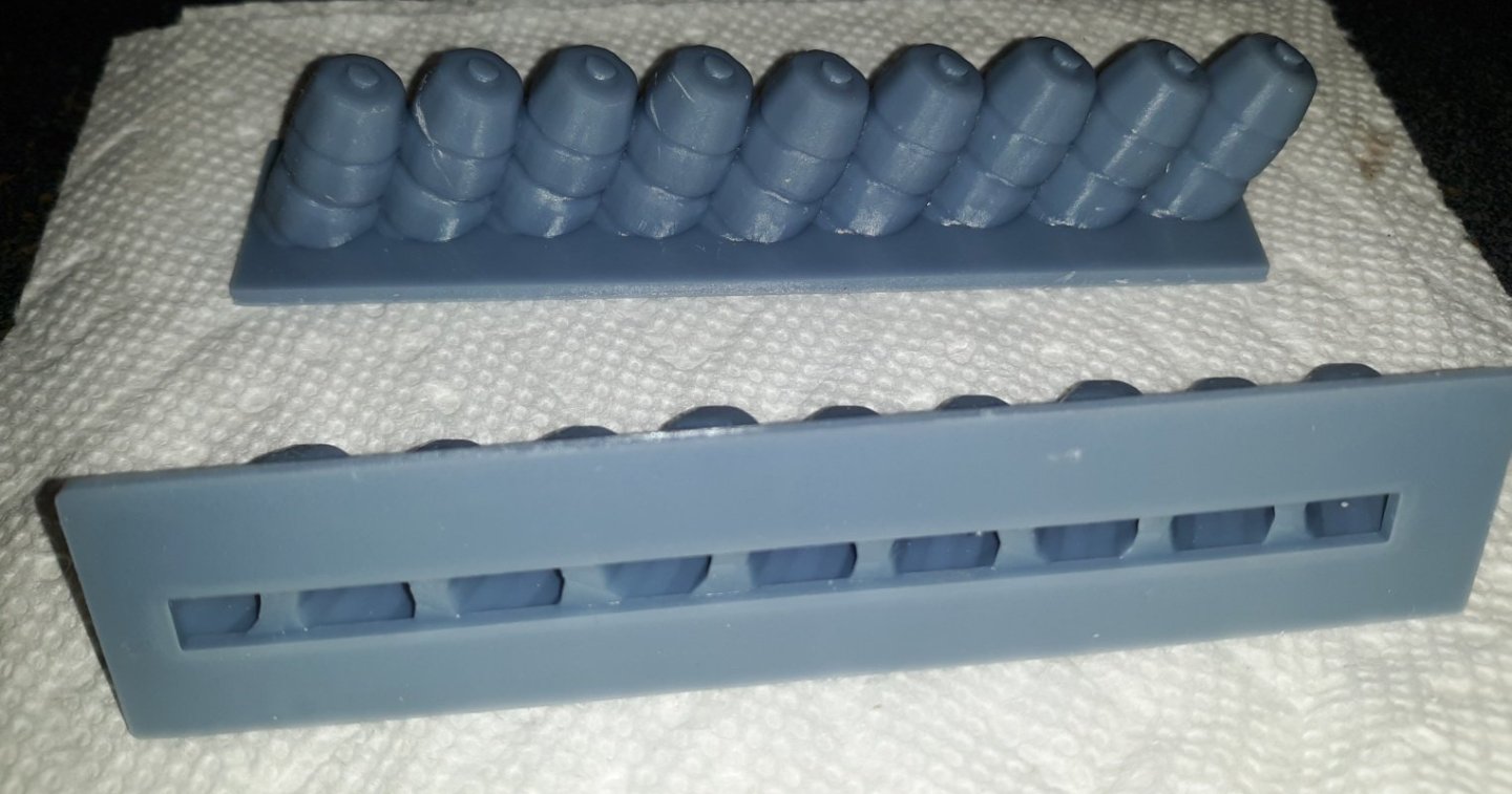
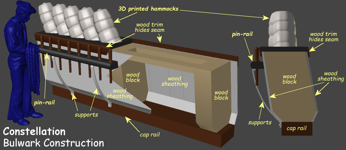
Before I can begin rigging the bulwarks have to be "finished." I'm working on one side at a time, and will do all this to the port side when the starboard side is done. The hammocks were 3D printed on "trays" which were modeled slightly wider than the bulwarks to accommodate any irregularities. This bit of overhang was ground off flush with the sheathing of the bulwarks using a sanding drum on a rotary tool. I then painted the inboard side of the bulwark, then the hammock trays black. I mixed some black into white paint to get a gray to paint the hammocks themselves, but I'll have to revisit that. Any gaps between hammocks and bulwarks was filled filled with a paste of epoxy and sawdust, and a covering board of stained basswood was glued on to cover the seam. This had already been done on the outboard side of the bulwarks. The pin-rails were already drilled for mounting pins, and those holes had to be transferred to the bulwarks, which I did with a pin-vise. So here's the pin-rails sitting in place. That covering-board's a little over scaled, and so are my belaying pins, so there's almost no room between the heads and the bulwark, so I'm going to pad out the pin-rails a little to get that room, before epoxying them in place. The last item to "finish" the bulwarks will be the metal supports under the pin-rails. These will be sheet brass and glued in place. Then it'll be onto the port side. Most of the time spent on this was waiting for paint/glue to dry. In the meantime I painted the ship's boats and 3D printed cradles for them. I also modeled new "crown-bitts" to replace the red oak one made years ago. I reworked my 3D model of the blocks to take 8mm brass sheaves, but I couldn't find anyone that had them in stock. I printed the shells for those anyway along with non-working blocks with fixed sheaves for things like the halyards, that don't move regularly, as opposed the the braces. I also printed smaller block for things like jib halyards, bunt blocks, etc. Some of these will get 6mm brass sheaves for working lines like bowlines and the "dummy braces" on the t'gallants and royals.


- 553 replies
-
- 2
-
-
- sloop of war
- constellation
- (and 3 more)
-
3D Naval Guns 1850s ~ 1870s
JerryTodd replied to JerryTodd's topic in CAD and 3D Modelling/Drafting Plans with Software
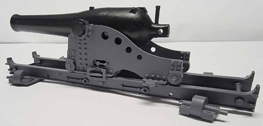
A little paint on the Dahlgren and printed the other Constellation gun, the 100# Parrot Rifle on a wooden pivot carriage.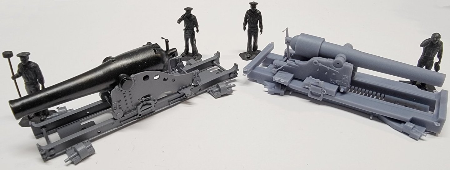
-
3D Naval Guns 1850s ~ 1870s
JerryTodd replied to JerryTodd's topic in CAD and 3D Modelling/Drafting Plans with Software
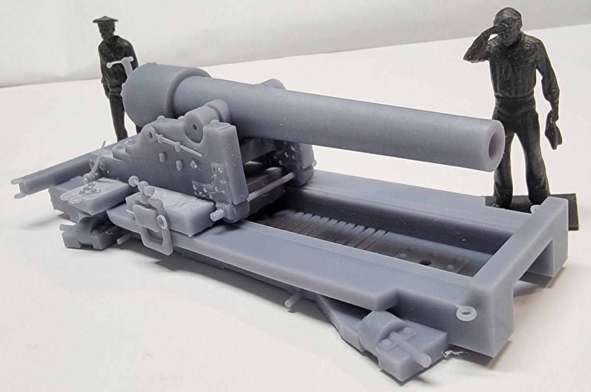
I finally got around to printing my own copy of the XI Dahlgren on the iron pivot carriage. Part of the elevation screw didn't turn out, but can be fixed. The size actually surprised me a bit, I didn't think there was that much difference between the IX and the XI.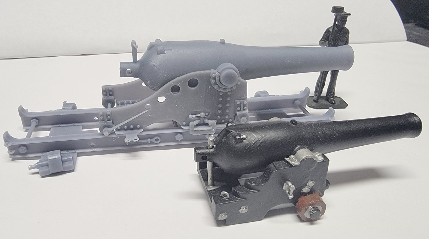
-
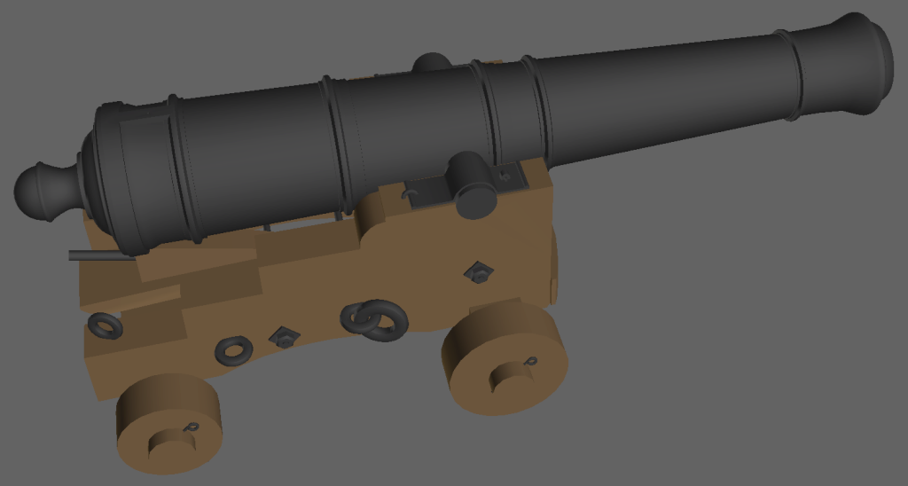
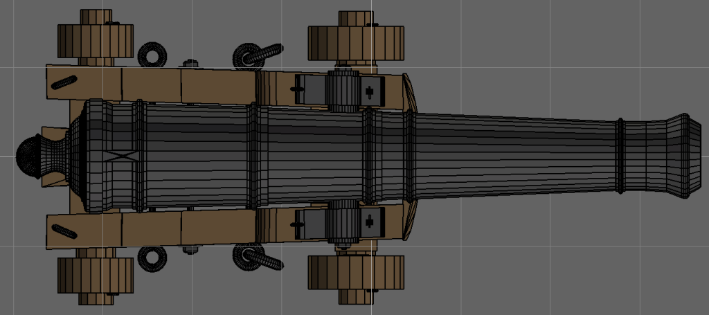
Since I'm modeling the Pride of Baltimore, I made 3D models of her 6 pounders. That angle isn't as severe as your kit calls for, and matched the taper of the gun tube more closely. Not trying to lead you into darkness, but the STL file's available for free on Thingiverse, and can be scaled
-
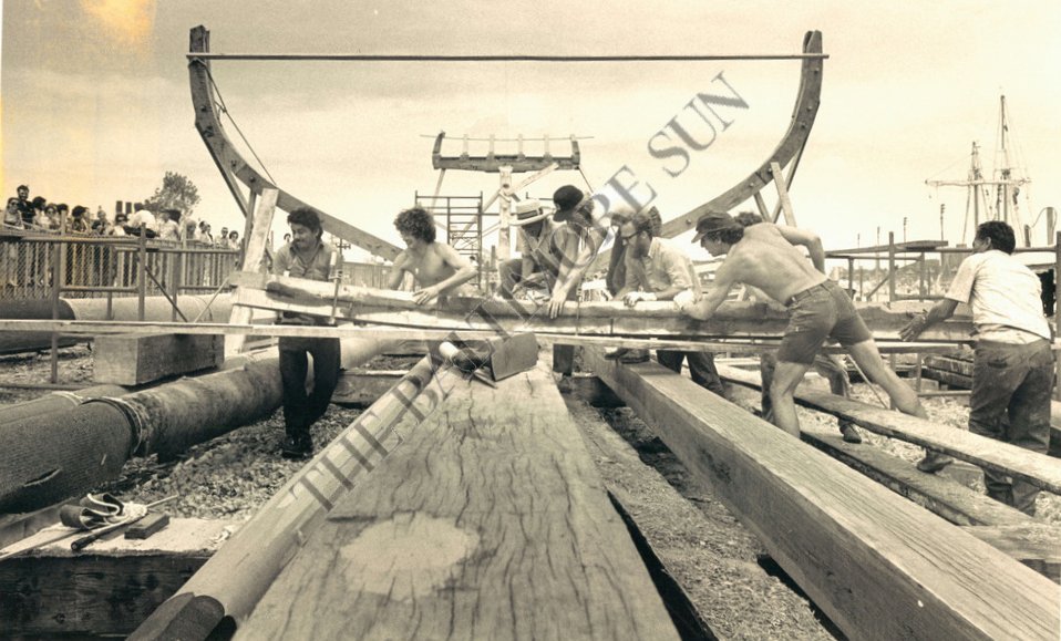
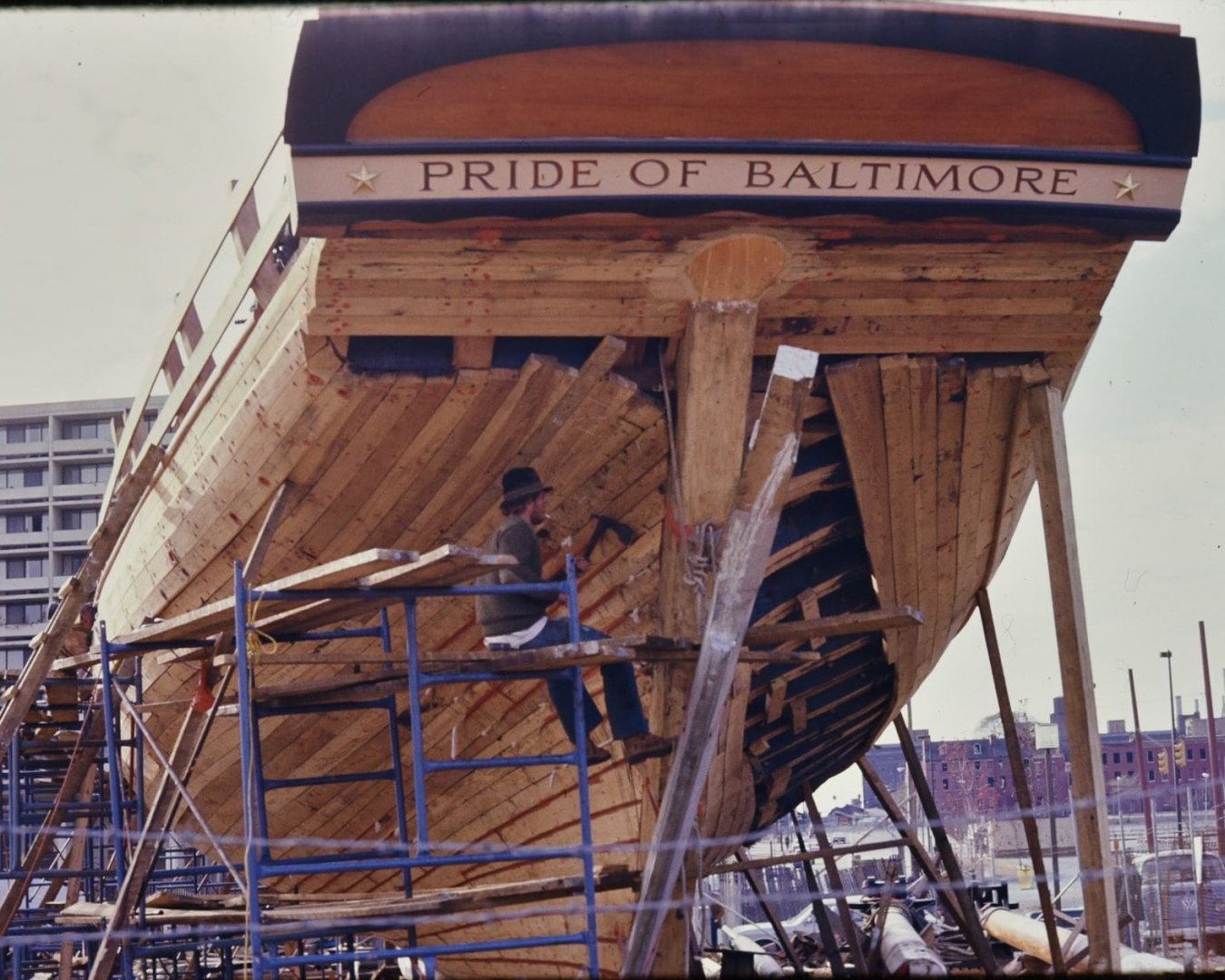
Just saw this log. I see you got the stern figured out, I had some picture for you on that, but I guess you've moved on BTW: Your gun carriage is reversed, when the sides are angled, the front is the narrower end, because the gun's bigger at it's breech than at it's trunnions. Here's some pic of the first Pride of Baltimore under construction. She was very near in size and rig as your model represents. (click for larger pics)

-
I can't see all those downward pulling braces (#s 15, 16, 26, 27), they would be impractical in practice. Because the yard moves up and down on the mast, you'd have to cast off the braces to be able to set the sail. The model and Harland show it where, at most, you have to ease the braces.
-
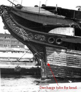
Down the "poop chute," of course
-
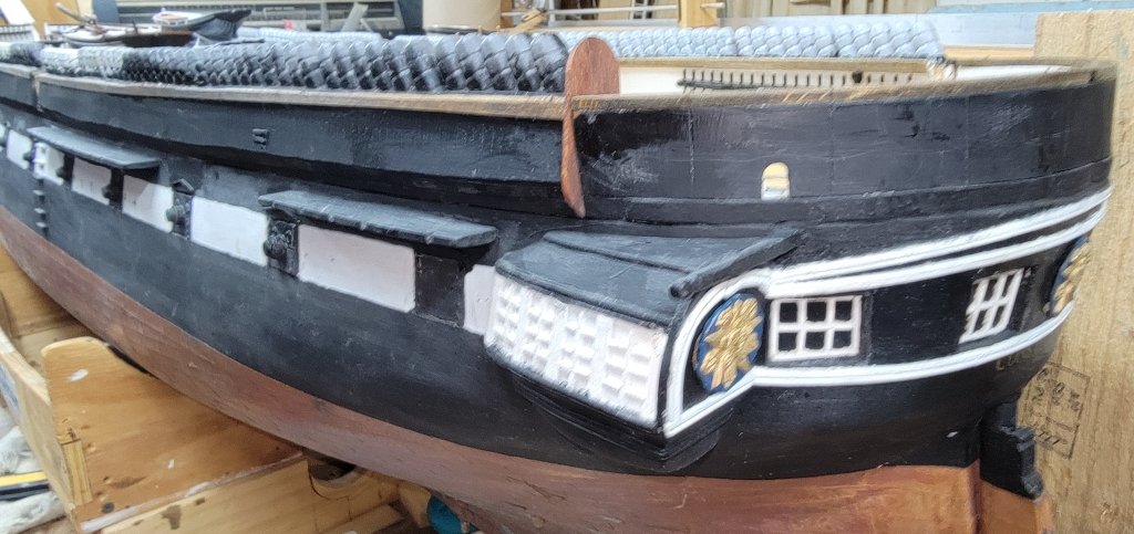
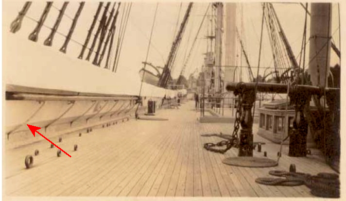
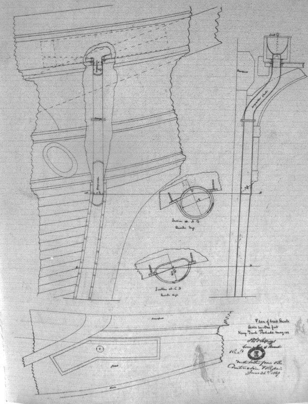
The fully enclosed head was a style with US warships from about the 1850s. Constitution was basically rebuilt around 1854ish but may have had her head enclosed before then. The head of Constellation built 1854

-
Interested in seeing where this thread goes I've had a decades long involvement with the Baltimore Clipper, having studied them, drawn them, helped build one, crewed on one, conducted "living history" on one, and building a working model of one (link in signature).
-
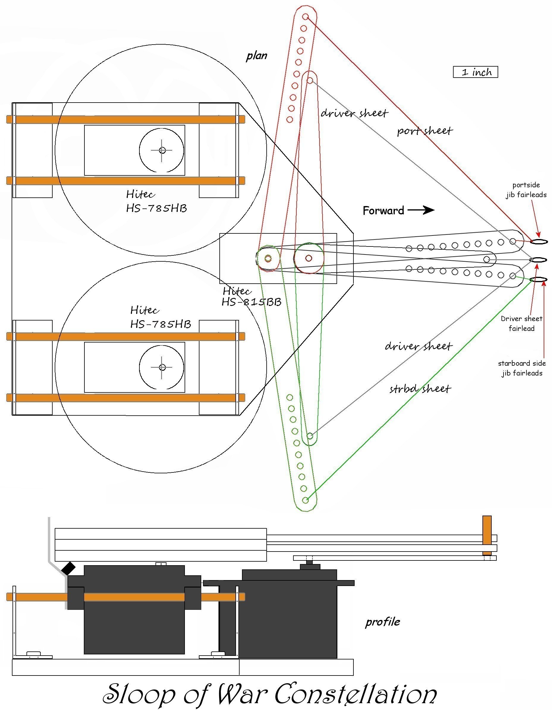
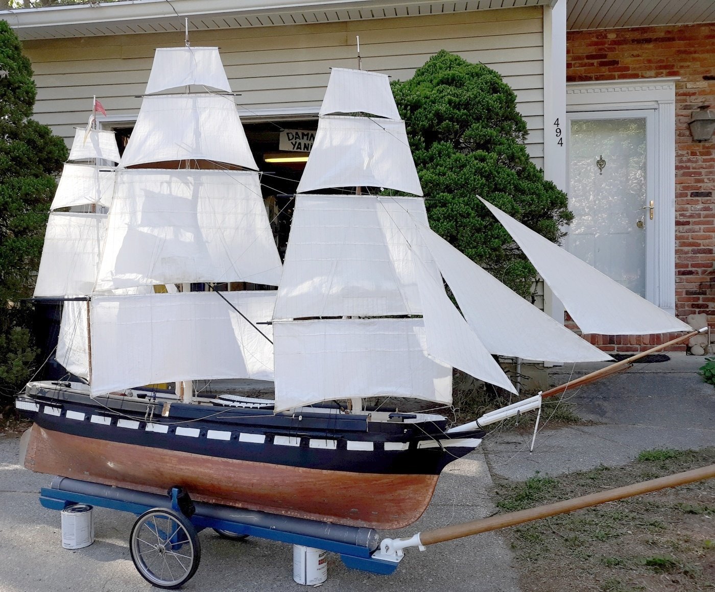
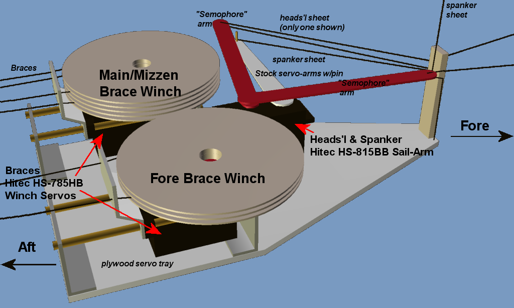
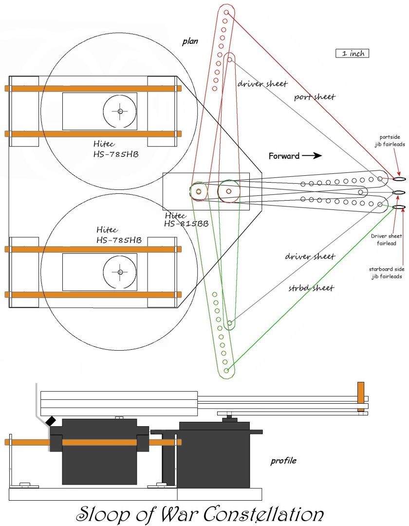
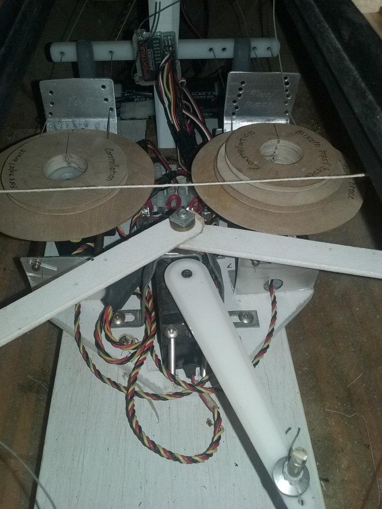
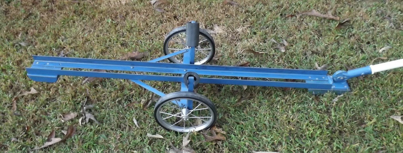
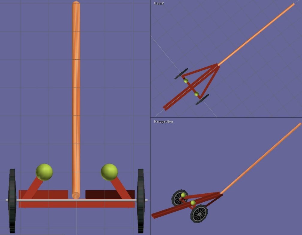
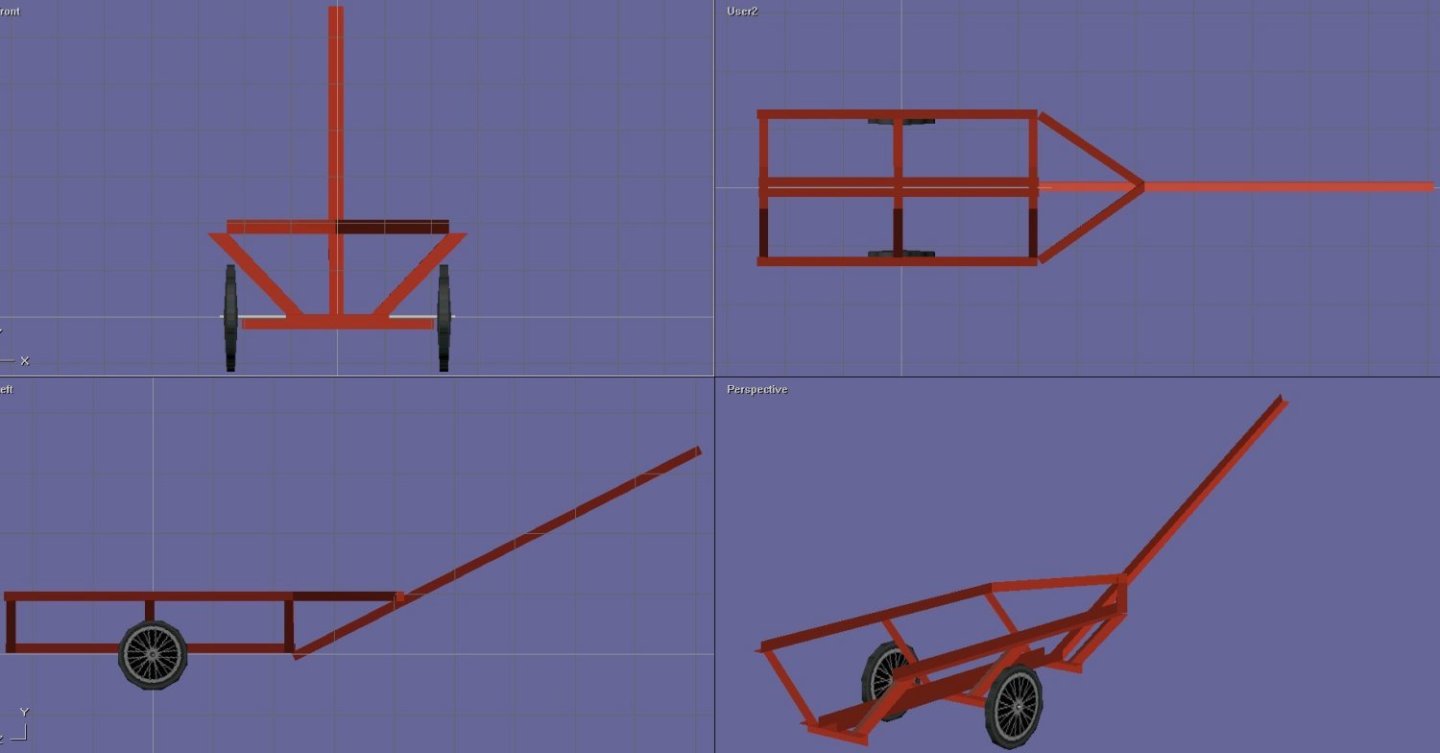
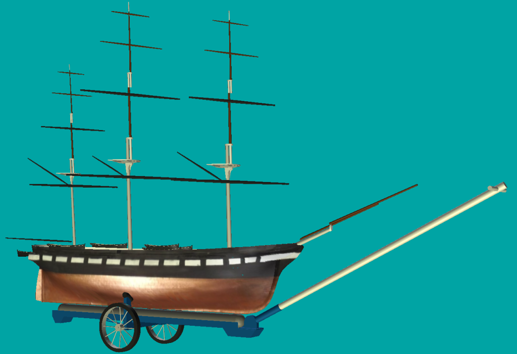
As usual everything is getting in the way of working on my stuff, but late at night, I sneak into the computer and fiddle with 3D models. Being short on time, I've been picking at models I did years ago, before 3D printing, meant to visualize ideas, and check for size, clearances, etc. (click pic for full size) This one, for instance I cleaned up, up-detailed, and smoothed the model of the Control Module for the square-rigger's braces and sheets. Next is the measured drawing of it, and then the actual item in the boat. This model was also an attempt to visually explain how Constellation's braces and sheets are handled, though there are still some folks that can't wrap their heads around it. This one was when I was figuring out a way to move, launch, and retrieve the model. Playing with ideas in the 3D modeling software starting with the left image and getting to the right one. This led to about as simple a concept as probably be done (below), all before cutting any of the steel bed-frame rails I used to build it, that turned out to be really tough stuff to cut. This is how the cart actually turned out, but I dressed up the model a bit with real spoked wheels, and a basic rig in the ship for size comparisons. I've been asked to bring the model to an event at Fort Howard Maryland May 28th, I'm told it's an instruction event for maritime reenactors that'll be open to the public. The model will be jury-rigged yet again, but she should appear a bit farther along than the last time she was out. My focus now will be installing those 3D printed pin-rails and having things done that will be hard to get at when rigging commences in earnest and the shrouds are in the way.

- 553 replies
-
- 2
-
-
- sloop of war
- constellation
- (and 3 more)
-
3D Naval Guns 1850s ~ 1870s
JerryTodd replied to JerryTodd's topic in CAD and 3D Modelling/Drafting Plans with Software
Someone on another forum actually printed my iron pivot XI Dahlgren on a filament printer at 200% which I think works out to 1:18 scale