
JerryTodd
-
Posts
879 -
Joined
-
Last visited
Content Type
Profiles
Forums
Gallery
Events
Everything posted by JerryTodd
-
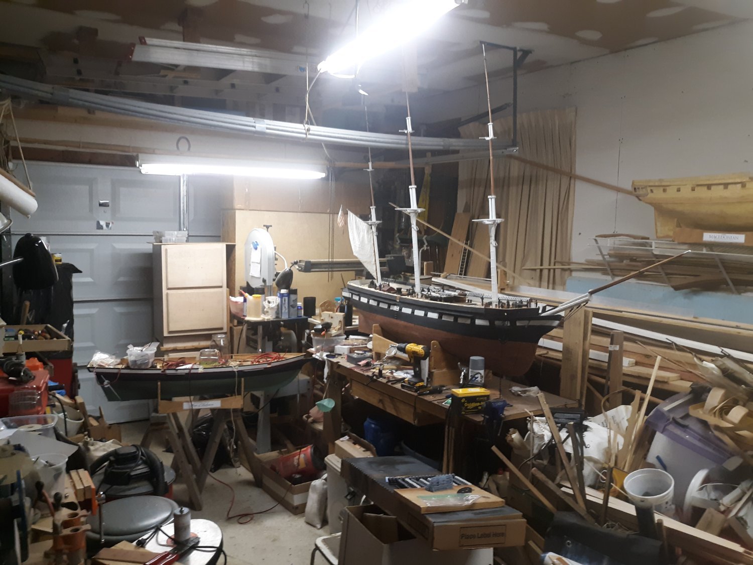
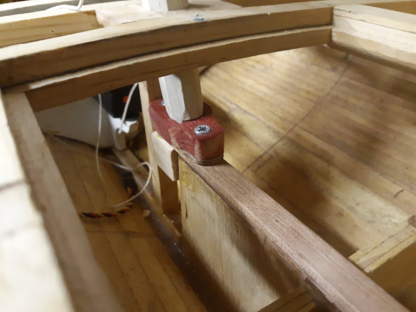
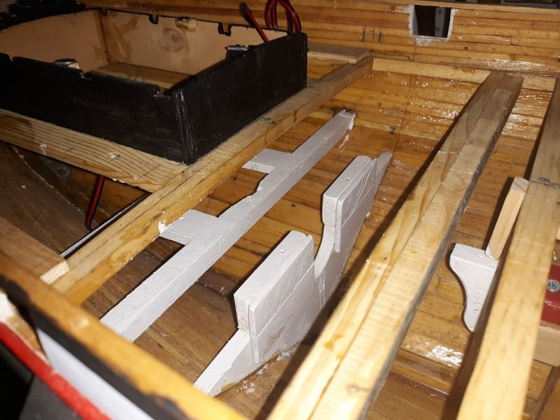
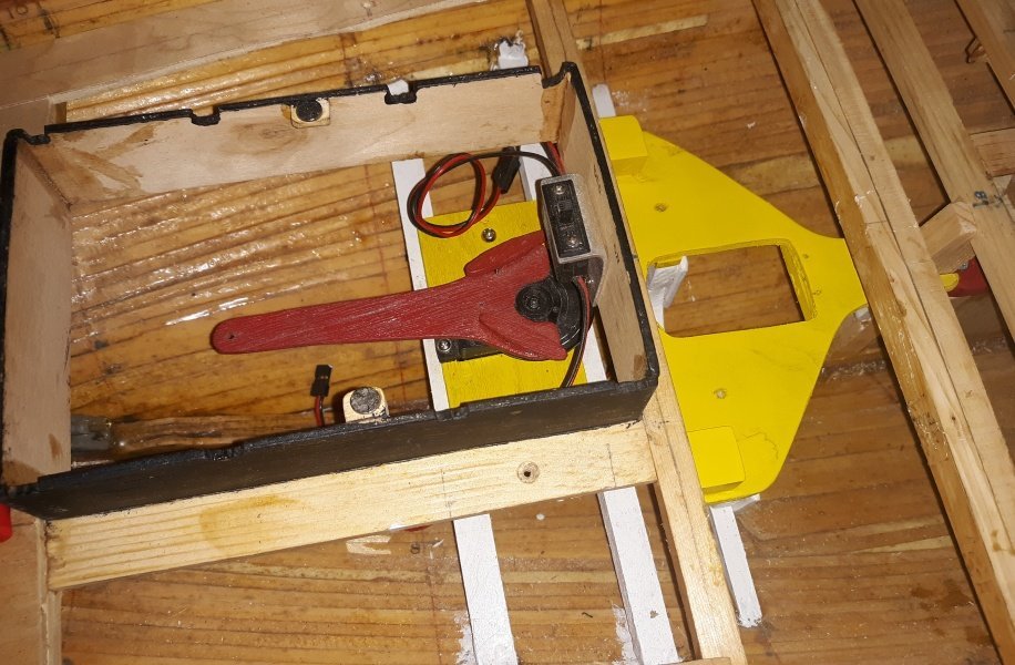
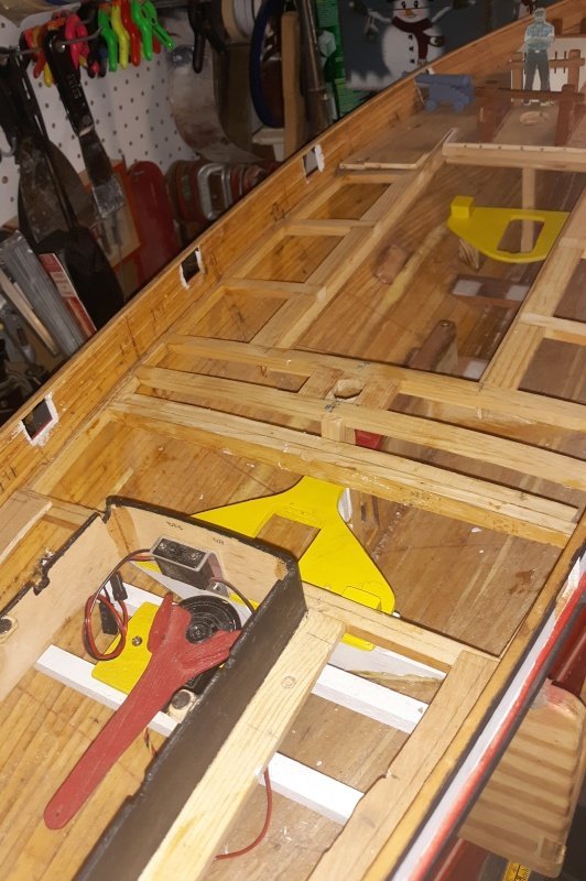
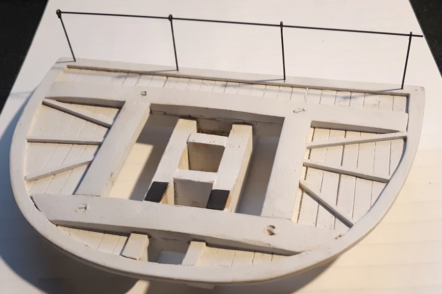
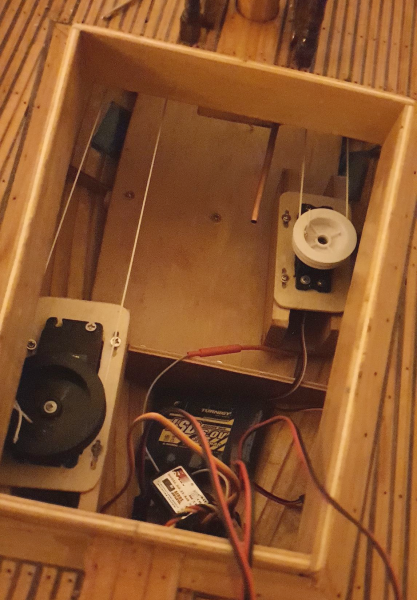
 Pulled out the old servo-tray that sat on the centerboard-trunk, and reset the main-mast step. The step was raised about 1/8" as the main sat a little too low. I didn't know that the tray would be in the way, but it's neater and cleaner with it out, and may fool someone into thinking I know what I'm doing. The old motor bulkhead got extensions and some paint, and an old knee was reused to catch the forward end of the new aft servo tray. I won't have access to this bit that pokes out forward once the deck is on, so instead of screwing it to a knee I installed to catch it, there's a block above the knee that holds it down. Two screws into the bulkhead at the back holds it in the boat. If I need to remove the tray, I take out the two screws I can access through the hatch, and the front slips out. The little blocks on the wings will hold the idler-pulleys up at the right level to the other winch drum. Then there's that lovely yellow paint. I don't even remember getting yellow spray paint, but I can't paint everything red. The forward winch tray is mostly made, I have to figure out it's mounting, which will involve the old rudder servo-tray blocks the thing is sitting on in the pic, but it needs raising up and the angle corrected. It will also have some fore-and-aft movement to it so I can adjust the tension on the loops.
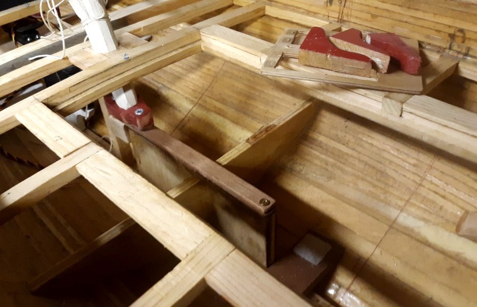
- 79 replies
-
- 4
-

-
- pride of baltimore
- privateer
- (and 3 more)
-
I pulled out the prop-shaft, cut back the stuffing box, and plugged it with epoxy. With that clear I made fitted a couple of beams where the rudder servo will go, made them into a frame, and epoxied it into the hull. I used a slow-set epoxy, so I couldn't do any more till it set-up. The steering will need a couple of turning blocks and fairleads to become functional. I placed some servos where the winches will go to do some measuring and it looks like I should get at least 22 inches (56cm) length of pull from each loop. That ought to be plenty to handle all these over-lapping sails.
- 79 replies
-
- 3
-
-
- pride of baltimore
- privateer
- (and 3 more)
-
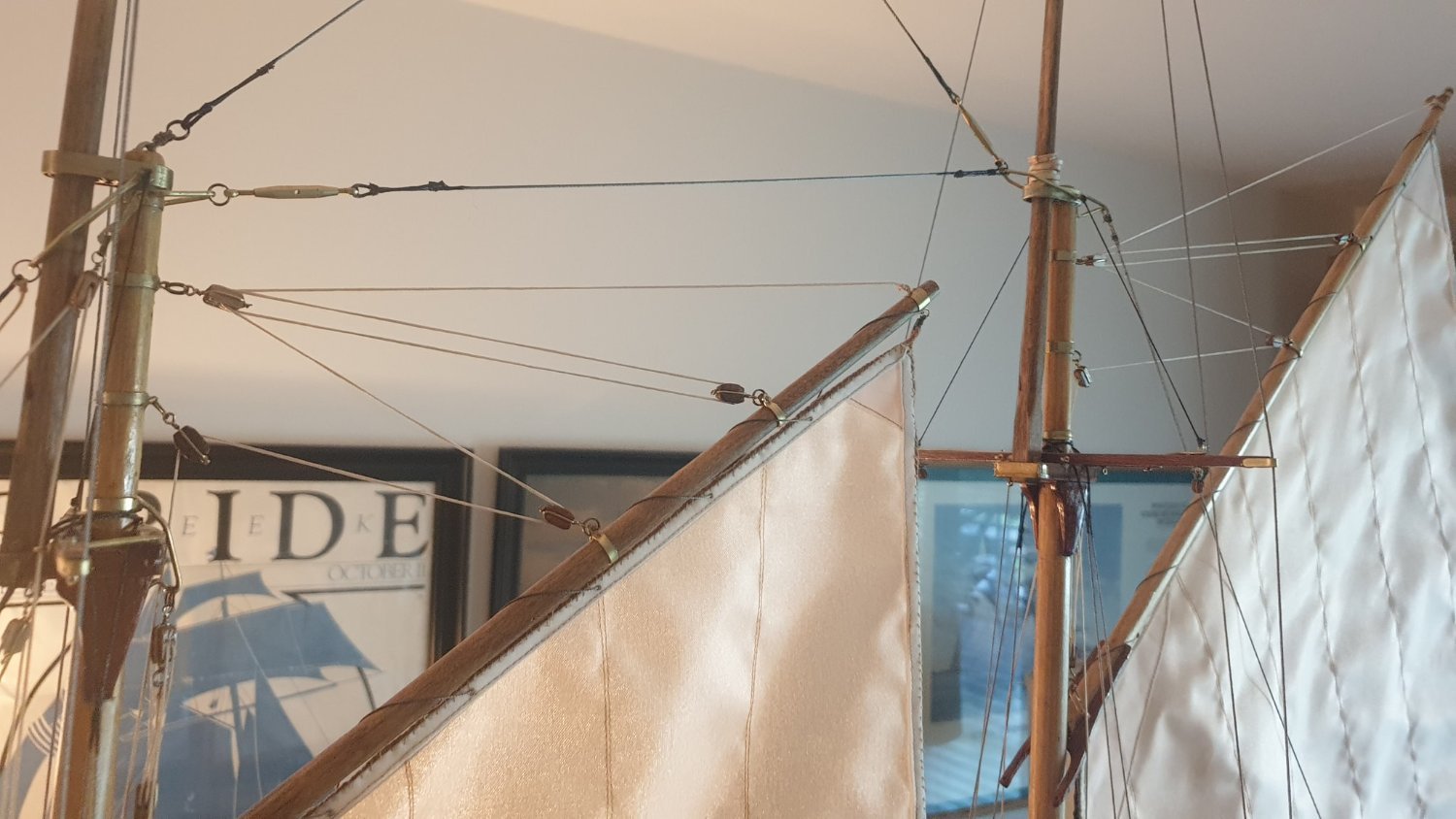
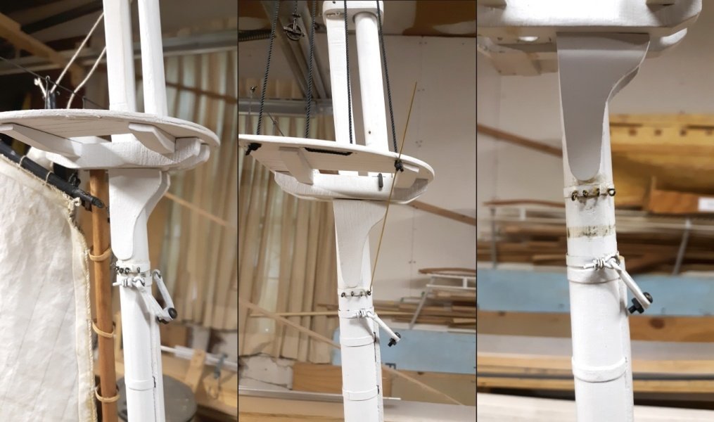
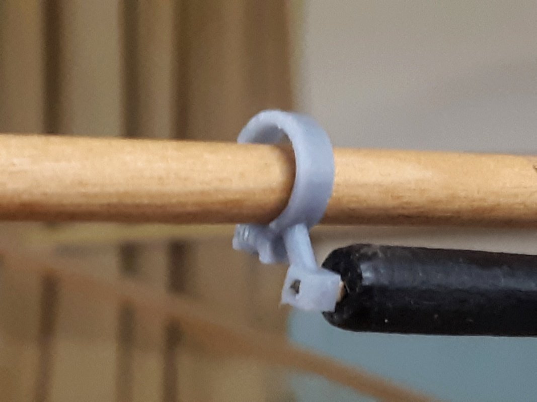
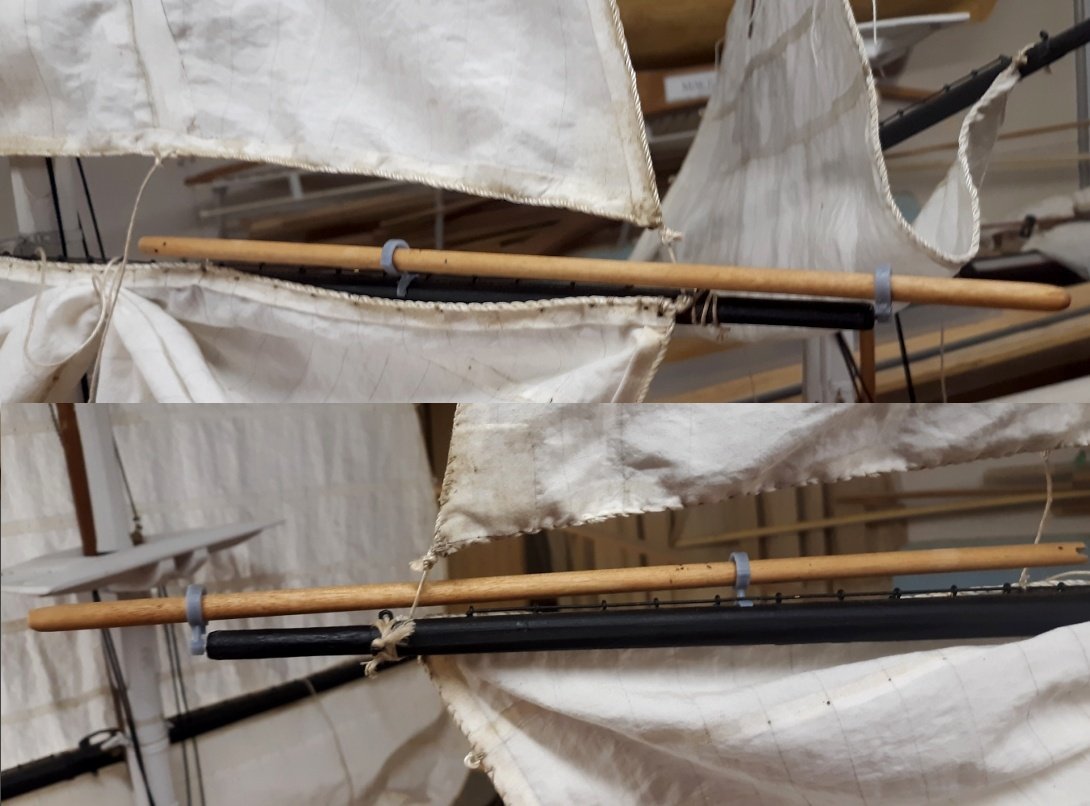
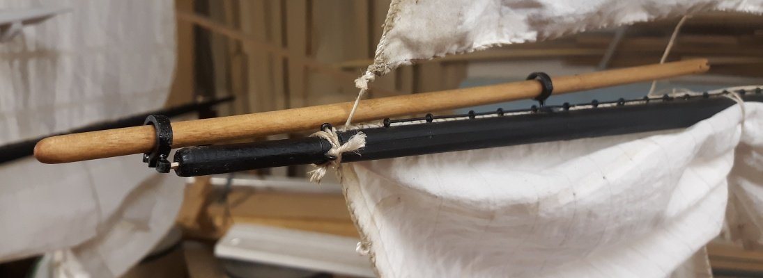
Made holes in the edges of the tops for the topmast dead-eye strops to pass through to the futtock shrouds. The futtock shrouds will be brass rod that will attach at to mast to a futtock band, which in this case is a strip od styrene wrapped and glued around the mast just under the hounds, with eye pins inserted. I thought of making a metal band with eye soldered on, but I don't need it that elaborate. The tresle-trees also got some brass plates (blackened) for my topmast fids to rest on without damaging the wood. The middle portion of the pic below is the mainmast, the black line some of what I'll be using for the topmast shrouds and some other standing rigging, rove up and down just so I can see how it looks. A brass rod is also stuck in there to see how the futtocks will work out. I was out most of today and worked on the rope-walk when I got back, soldering leads and prepping DPDT switches. I finally had to take a break either because I was tired, or ran out of places to sit thing down. I think tomorrow the shop will need some straightening up before I can get back to anything else
- 553 replies
-
- 3
-
-
- sloop of war
- constellation
- (and 3 more)
-
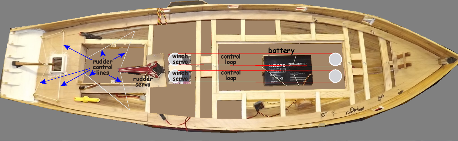
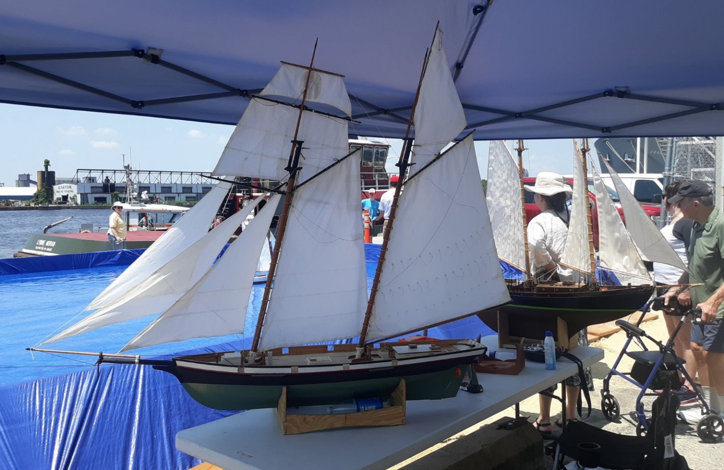
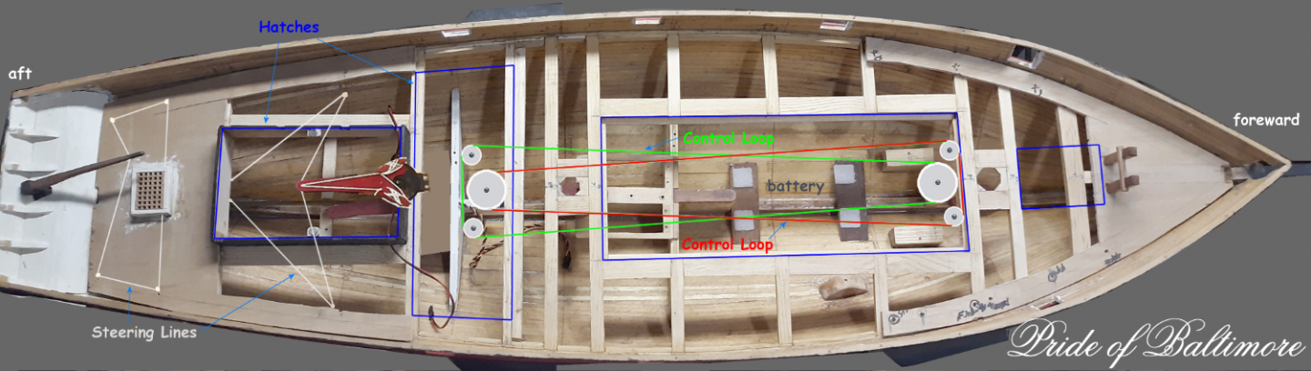
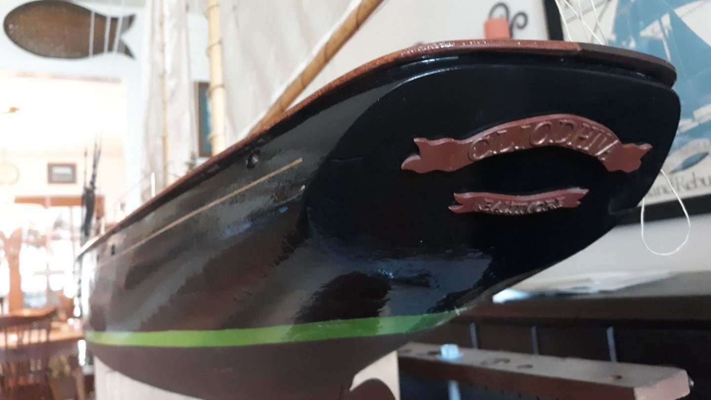
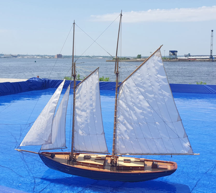
I pulled everything out except the prop shaft and stuffing box (which is just a tube). My smallest allen-wrenches seem to have wandered off so I can't take off the prop and bushings yet. Once that's out of the way, I'll look at mounting the rudder servo and making new fairleads for the steering gear. The wood blocks forward are epoxied in, as are the block where the rudder servo was mounted, I'm leaving them in place unless they get in the way, since it'll be a chore taking them out with damaging the hull. The aircraft plywood servo tray just forward of the mainmast will come out as well. I edited in a new diagram that ought to be a little clearer to see the controls, hatch outlines, and steering lines. I'm thinking instead of running the control loops side-by-side, I'll put one winch aft, and the other forward so the control-loops work within each other. This should make dealing with the connections through the hatches easier, since the whole system will be narrower. I also got 50 pounds (22.7kg) of lead shot a few days ago, so I have to determine the size and shape of the bulb I need to cast. That will get bolted onto her removable fin and I think will be in the neighborhood of 20 pounds (9kg). Some shot in baggies will go in the hull for trim, I figure one in the bow and the other in the stern, each about a pound. Pride was on display at National Maritime Day on May 22nd. Here she is on the table with Cliodhna. Mark's schooner isn't a particular scale, but it's very close to Pride's 1:20.
- 79 replies
-
- 3
-
-
- pride of baltimore
- privateer
- (and 3 more)
-
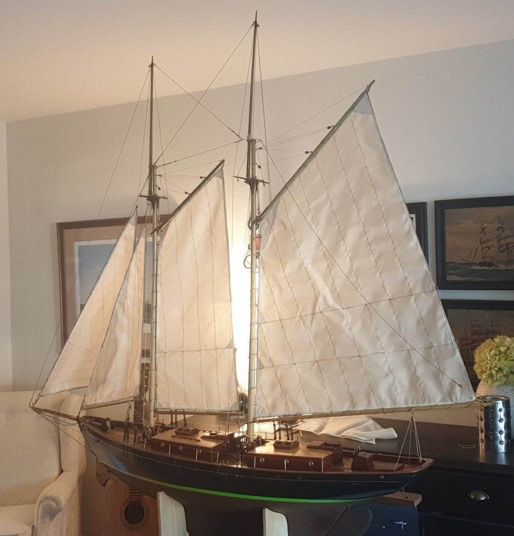
Yeah, Mark's into his Irishness, (which spellcheck wants to change to Garishness). When they opened a Guinness brewery here in Maryland, you would have thought it was the second coming. As a Scotts-Jew, I have completely different stereotypes to live up too. As for the prop, I'm afraid even a pretty, 1 inch (25mm) prop wouldn't be up to the job. I considered putting a motor on the end of Constellation's the ballast tube with a nice big nylon prop from a Sequin steam tug kit, but someone tried towing her once, with a dedicated 1:24 scale tug boat model in a 4-5 knot breeze and could hardly make any headway against all that sail. Instead, I'm looking at building a 6 or 7 foot pram that I can car-top by myself, and chase these things around with a trolling motor. Here's a couple more pics of Cliodhna. She's a yachtified fishing schooner. Her lines are based on a hull he liked in a 1930's magazine of boat designs. When the hull was built, he thought she looked "stubby" so he lengthened it about 4 inches. All her hardware details are based on Chapelle's The American Fishing Schooners. Mark made all her hardware except for the turnbuckles and deadeyes. I modeled and printed the stern-boards, wheel, and windlass for him. She's clean and neat, and the brass is all polished and varnished because the wife didn't want a stinky old fishing boat on display in the living-room. If I had done that hardware, I wouldn't have hidden it under blackening or paint either. The model is one of those that's beautiful at any distance.

- 79 replies
-
- 5
-
-
- pride of baltimore
- privateer
- (and 3 more)
-
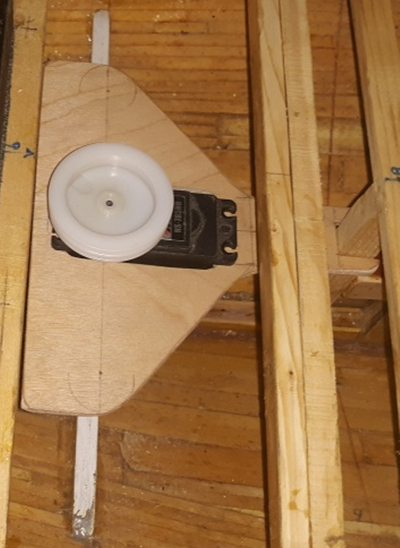
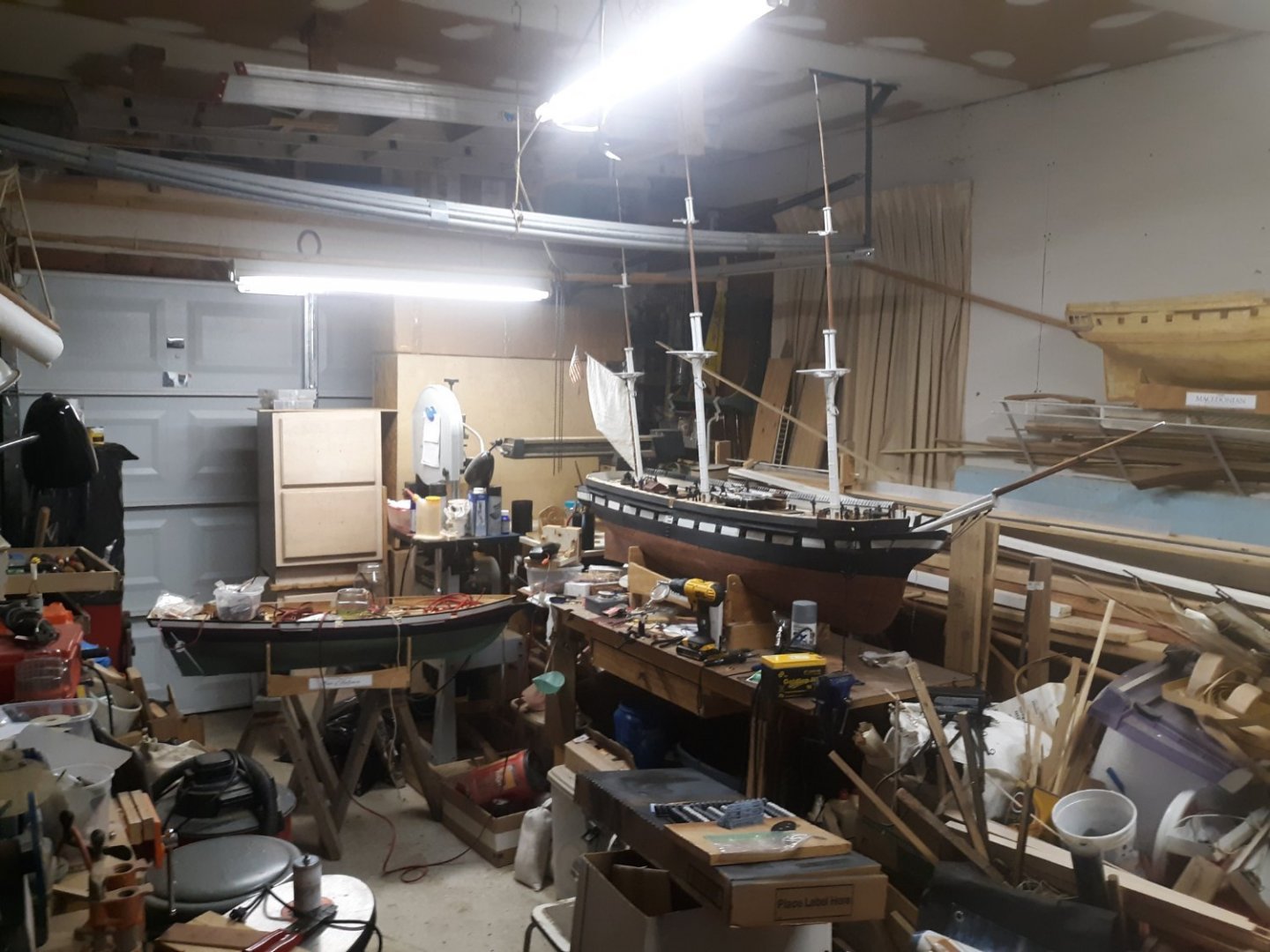
My friend Mark sailed his 46 inch schooner Cliodhna (Clee-na) for the first time in the pool at National Maritime (May 2022). He controls the sails with a sort of clothes-line system driven by a winch. It's actually a common system in RC sailing models, especially schooners, and what I originally intended to use in Pride. The winch drives a closed loop and the sails' sheets are attached at points so the loop's travel pulls the sheets the requisite length for each sail. Mark used one loop to control the over-lapping jibs (there's gonna be a jib-tops'l), and the other loop controls all the rest of the sails (the ones with booms basically). Watching this work so well in the pool, especially with the over-lapping jib, I started rethinking Pride's set-up - again. I could finish this model if I could work out the controls, and what I was working on I don't think was going to work. Sometimes the first idea winds up being the best idea, with some adjustment, First off; I already plan to remove the motor. There's no way that that 1 inch prop is going to move all that sail in even against the slightest breeze. The motor will go to the upgrade of my rope-walk. With the motor gone, the Rudder servo can be moved aft to where the motor was, closer to the rudder and the receiver, so I won't need an extension cable. Two winch servos with be re-mounted just forward of the rudder servo, and the other end of their loops with be at the forward end of the main hatch, just behind the foremast. This should get me enough length to control everything, even, I hope, the square tops'l. Another step towards getting this girl in the water is the arrival of 50 pounds of lead shot. Now to gather the materials and courage to cast a 25 pd lead bulb.

- 79 replies
-
- 3
-
-
- pride of baltimore
- privateer
- (and 3 more)
-
I wish I could find some images of the way all that rig is put up, there's got to be places for the shrouds, stays, sheets, etc, all attach with some sort of corresponding hardware I ought to include in my model. Not to mention now having an urge to do an RC model.
- 553 replies
-
- 1
-
-
- sloop of war
- constellation
- (and 3 more)
-
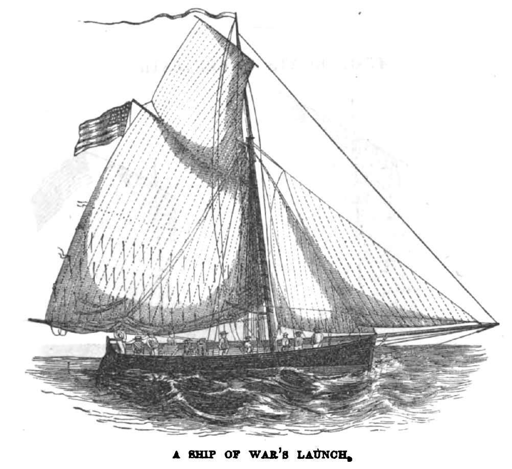
Since I need to make spars and sails for the boats, including the launch, I went digging around to find out what I needed to make, as well as other items that go in the boat. I looked in Nare, Luce, Brady (The Kedge Anchor), the Navy Ordnance Manual of 1866 (haven't found an earlier one yet), and a few other, mostly British works. Besides finding out that two extra oars are to be "triced up" under the thwarts, the rest to be bundled and gasketed to the thwarts (which implies a single "bundle"); the mast and sails to be "kept in the boats" the sails in a "painted cover made for them;" davits boats' rudders to be tied on so the line must be cut to remove the rudder; and a list (with reference to the Ordnance Manual) of what goes in the boat when going boating. A lot of this I don't need to model though the crew getting things ready to launch the launch is a nice little vignette, maybe even prepping a quarter-boat as well. At any rate, I do have to apologize to Roger for disagreeing with him about the boat in the painting. Apparently a ship's launch is a far more complex machine than I had come to believe based mostly on what's shown in images, and models (even period models); because in The Kedge Anchor (1849 and in later editions) I found this: That could very well be somebody's launch, but... it ain't Constellation's, cause it's flying a British flag at the peak.
- 553 replies
-
- 2
-
-
- sloop of war
- constellation
- (and 3 more)
-
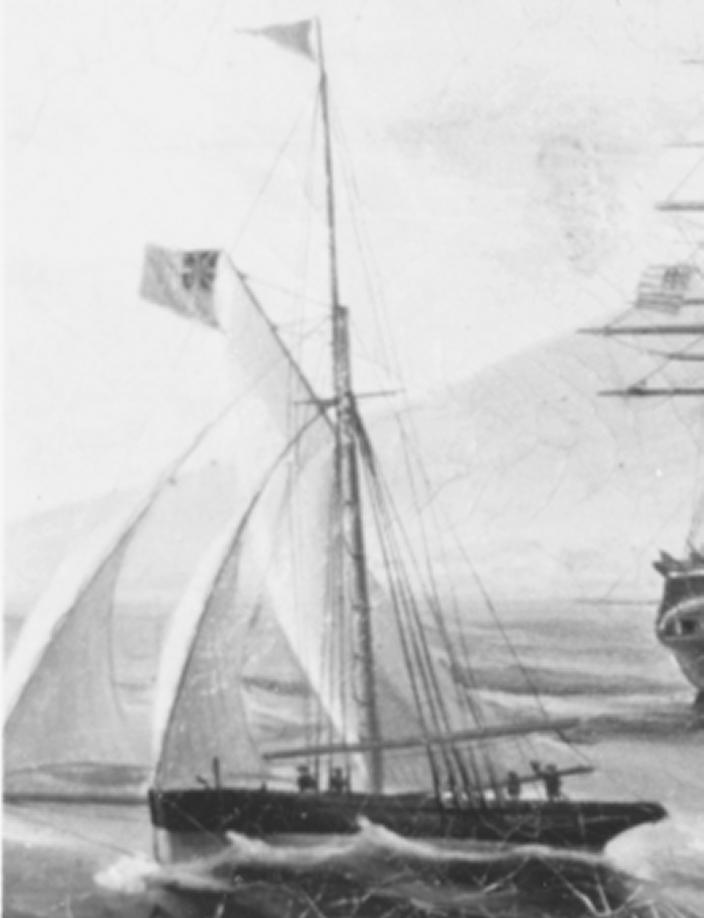
But that boat has permanent standing rigging and a topmast with cross-trees and trestle trees, as well as a yard lowered across the rails - a very common thing seen in images of naval cutters. Also, based on the figures on it, is larger than 32 feet, It could be a courier boat from the Naval attache or consulate, or simply the mail boat as there's several American vessels at anchor. It's certainly not a ship's launch.
- 553 replies
-
- 1
-
-
- sloop of war
- constellation
- (and 3 more)
-
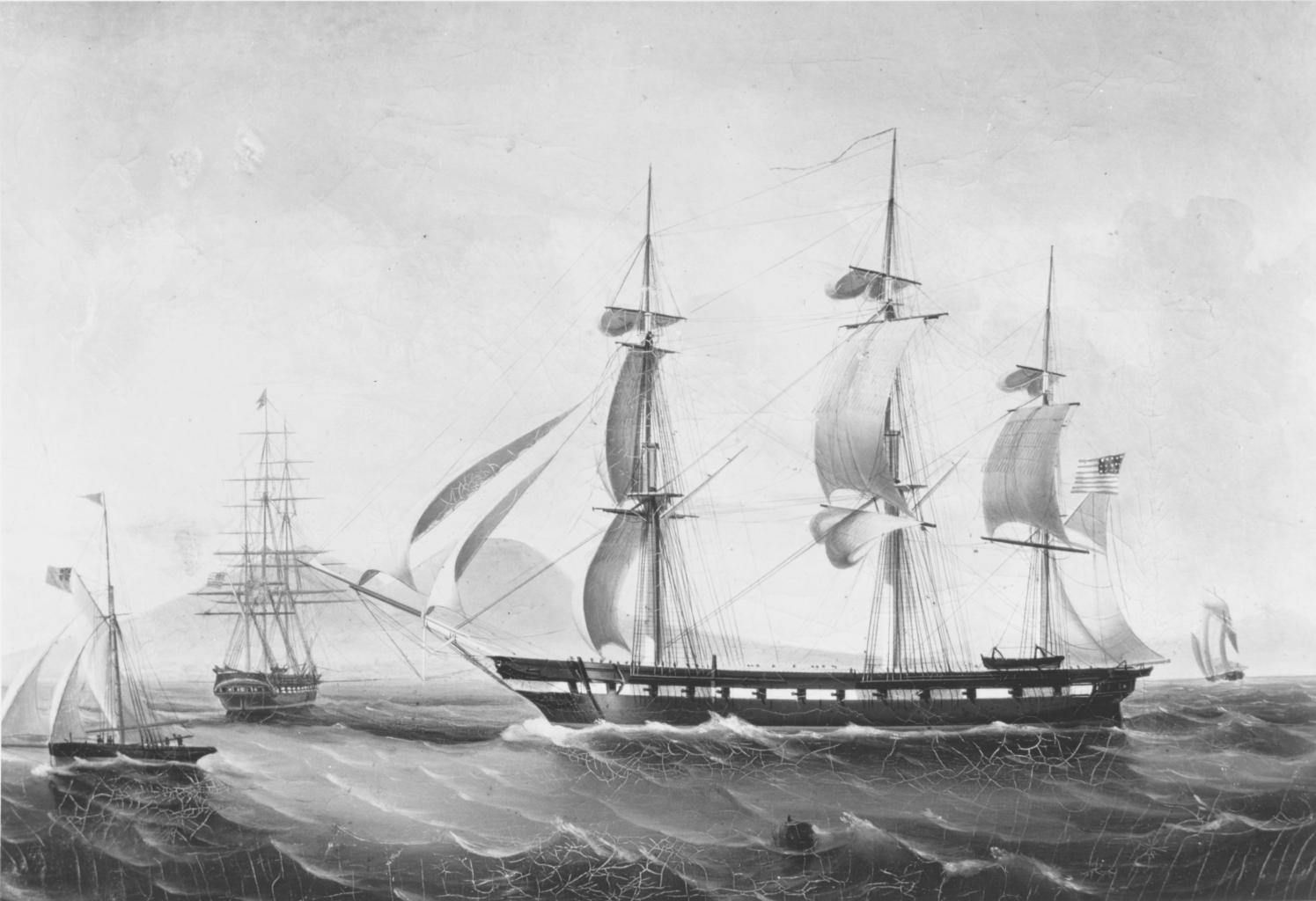
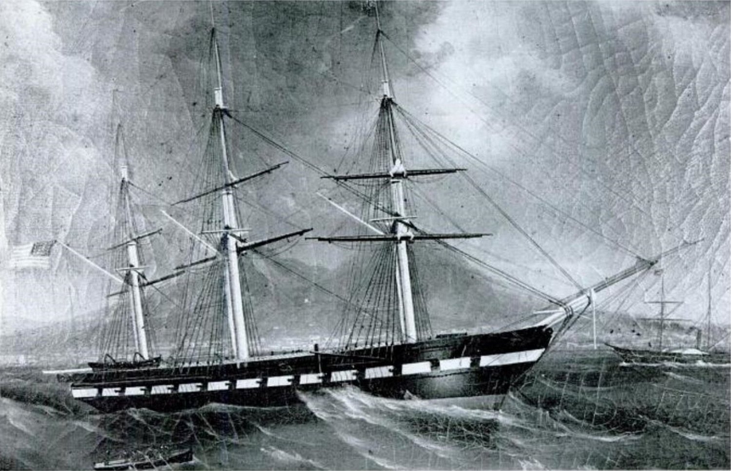
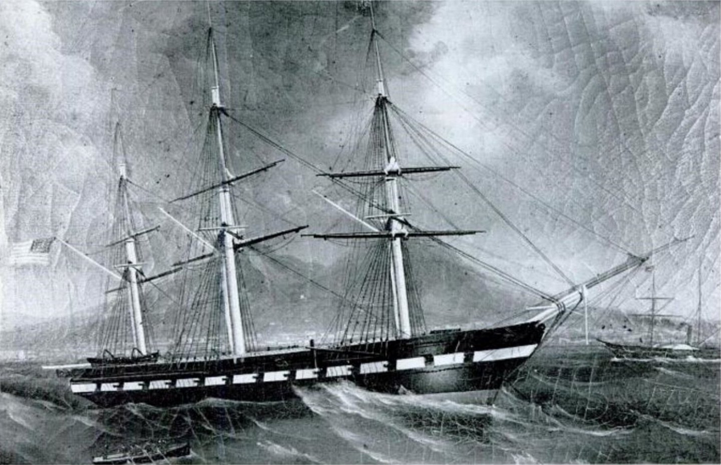
In this image? That's a a cutter that probably 60-90 foot on deck. The launch was only 32 feet and two masted with a sprit-schooner or sprit-ketch rig. DeSimone had a lot of experience with ships, and their appearance, and while including a lot of detail, left out a lot as well. I imagine he did a sketch, maybe a quick painting to get the tones right, then went home and filled in the rest from memory and experience. In the 1856 painting there are no lower deadeyes on the topmast shrouds, or any at all on the off starboard side. The bowsprit, spencer masts, gaffs, and booms, seem to cycle between bare wood, black, and white and it's hard to say if they were repainted, or the artists just made it up. In a diary it says the ship was painted while in Naples and the captain had the ship painted all black with no gun stripe. She went on a patrol of the Med and the gunstripe was repainted when she returned to Naples. So, it's possible the spars actually were different colors every time DeSimone saw the ship. If you look back in this thread a ways, you'll see the signal flag issue regarding the signal flown at the mizzen truck in the 1856 painting. I still cannot find those flags in any signal system. Another painting that's incorrectly IDed online as another ship (I forget which now) but is certainly Constellation pre-1860 and shares odd details with the 1856 painting, like the missing topmast shroud deadeyes. An all the gaffs and booms are white. One of her boats, probably the port side quarter boat or second cutter, is approaching from the bottom of the painting. I've never found color versions of this or the painting above so far. This drawing of the ship in 1864 by DeSimone at Naples, I just found at the Mariner's Museum in Newport News Virginia. It has a lot of interesting details shown, and omitted, for instance she has the wrong number of gunports. Some of her boats are shown, but as you pointed out, they don't really get much attention. One image I'm still searching for was a photo taken from a hill on St Helena that's mentioned in a diary. That would probably be the first, and earliest photograph of the ship ever taken.

- 553 replies
-
- 2
-
-
- sloop of war
- constellation
- (and 3 more)
-
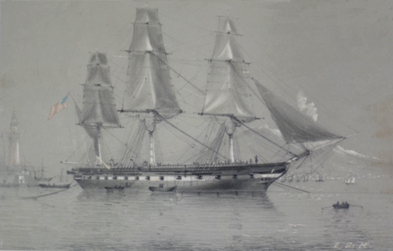
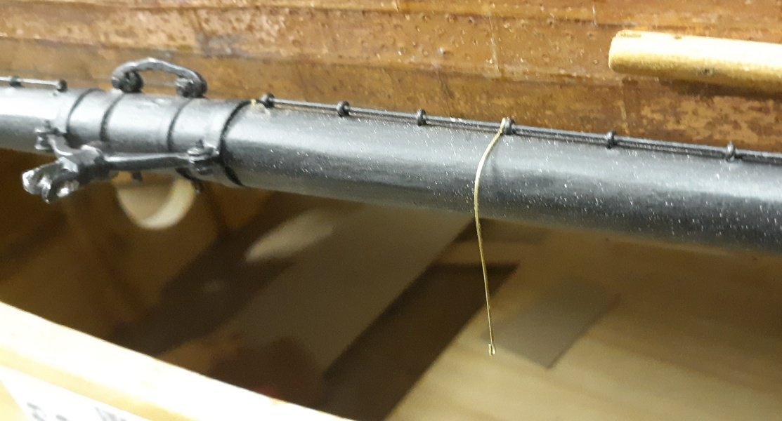
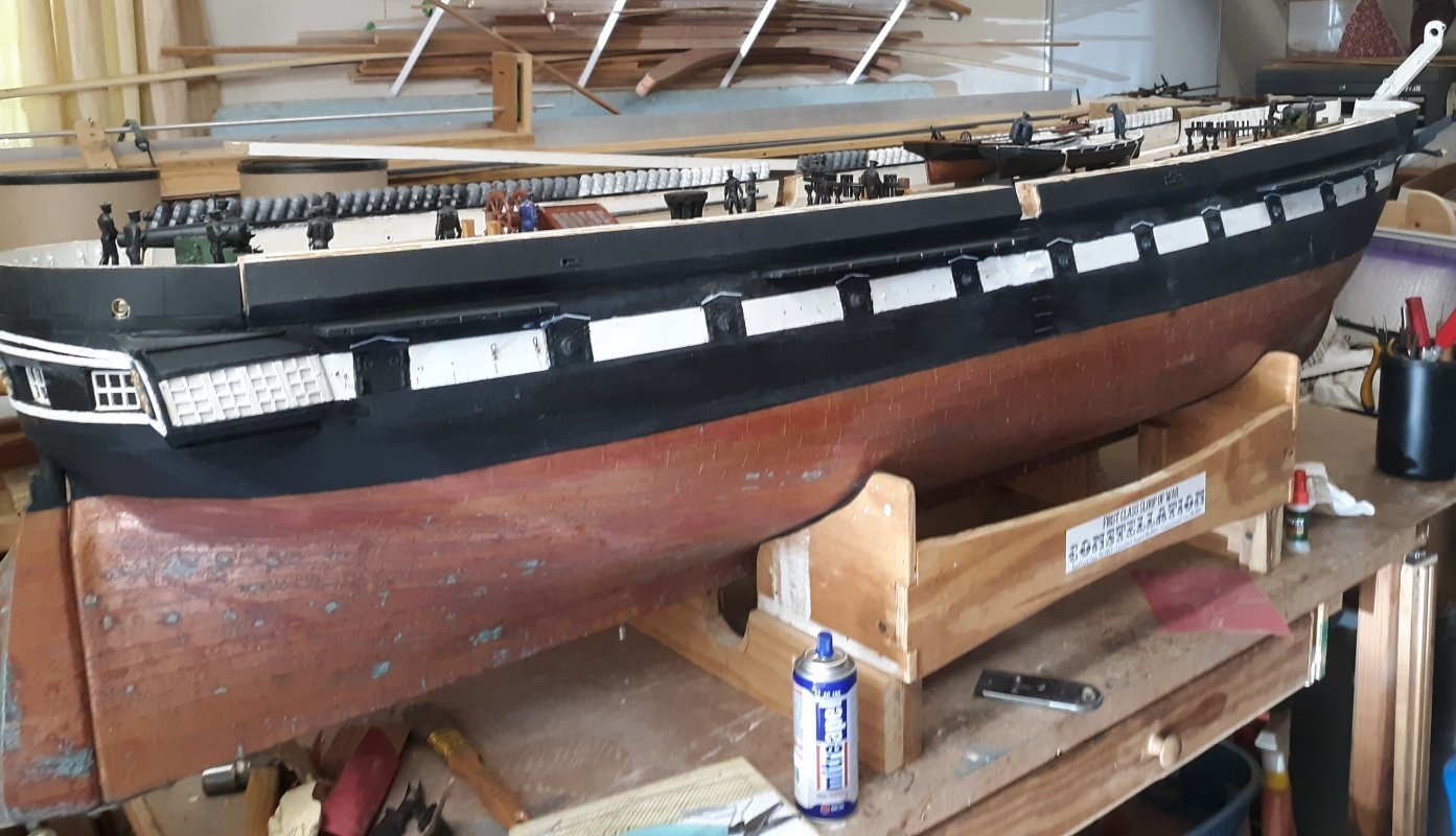
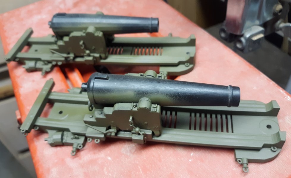
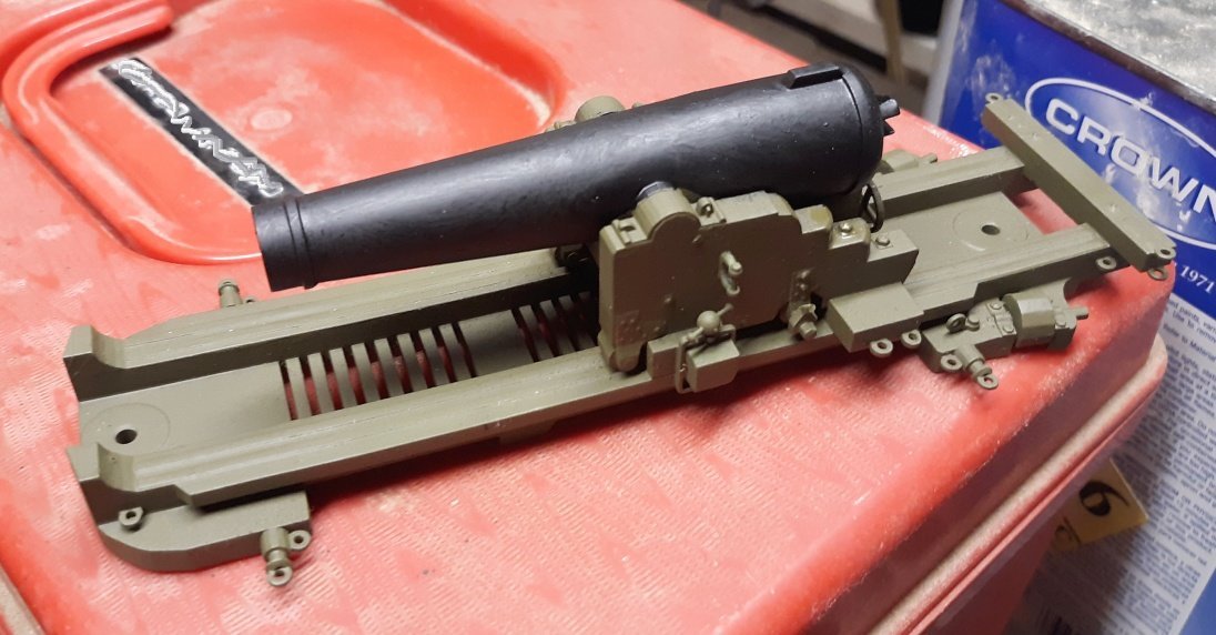
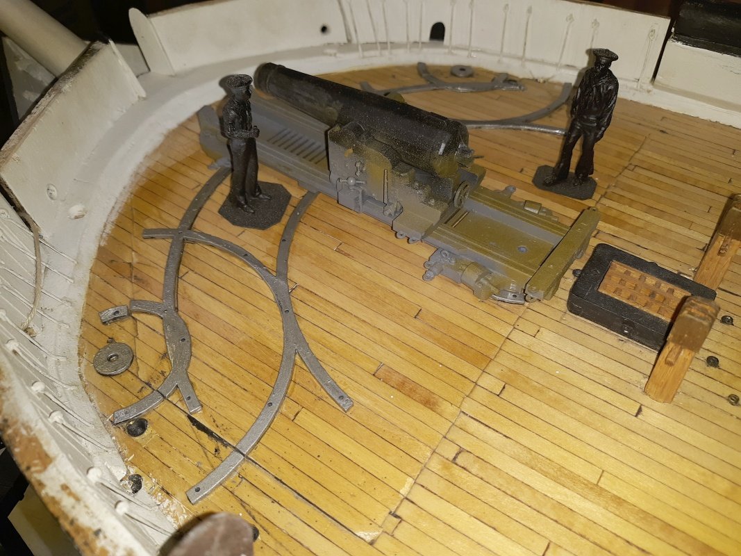
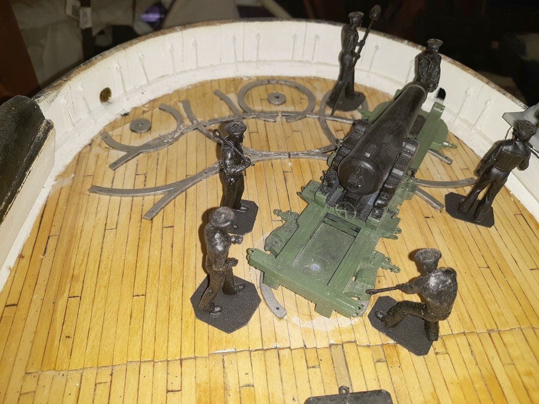
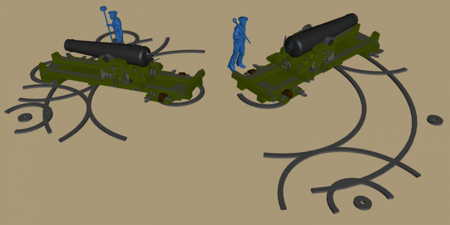
I painted the pivot guns, but the photos show more touch-up is needed to be finished. I need them painted before I attach them to the hatches they sit on, then they can be rigged with their tackles and what-not. With the intent to get the yards fully rigged with foot-ropes, blocks and the like, I've been thinking how I want to handle the stirrups. In reality, the stirrups are a line with an eye on each end a little over 3 feet long. One eye is seized to the jackstay and the stirrup hangs over the bank of the yard. The foot rope passes through the bottom eyes. I'm still looking to see if is was Navy policy to seize the foot-rope to the stirrup or not. In photos of the ship where they can be seen, she's already a training ship and the foot ropes have a knot on either side of the stirrup eye. Since I have 56 stirrups to make for the 12 yards, I'm thinking of just making then from wire as show in the picture, blackened or painted, of course. I did one to see if I liked it, and was about to go to work making them when I realized I bought all this .020 brass to make the dead-eye strops, so I switched gears and started looking at chainplates again. I cleaned up the work area a bit, and took the rest of the jury-rigging off the hull, like eyes for the temporary stays, and some of the chain-plates that were screwed on. I started cleaning up the chainplates sets I had made so far, finished the ones that were nearly done, and fix some soldier joints. I remember trying to decide whether to uses a #1 bolt and nut to attached the dead-eye to the chain-plate or peen an escutcheon pin (brass nail) to do the job. The nuts and bolts would be expensive, especially right now with inflation the way it is, so I'm going with the escutcheon pins. They're a bit hard and peening them is difficult, so I annealed one to see it that worked better, and it did. Next I started working on some jigs to shape the strops, links, and the strap between the dead-eye and the link. I also gave one set a coat of primer for the picture. In all there's about 26 pairs to make almost all a little different as the link gets longer with each set going aft because of the angle of the shroud. That means each pair has to be assigned it's position on the hull as they're all basically different lengths. The upper deadeyes have the same sort of strop and each shroud gets a thimbled eye with a pin holding them together. I plan to 3D print the tear-drop shaped thimbles, and use the same peened pins to attach the strops, but I have a feeling actually doing all that is going to be very complicated and needing of more hands than I possess. I thing peening the strop to the thimble, then seizing the shroud around the thimble with the upper dead-eye held by a measured bracket so all the upper deadeyes are consistently spaced is probably the easiest way to deal with it. We'll see when I get that far.
- 553 replies
-
- 3
-
-
- sloop of war
- constellation
- (and 3 more)
-
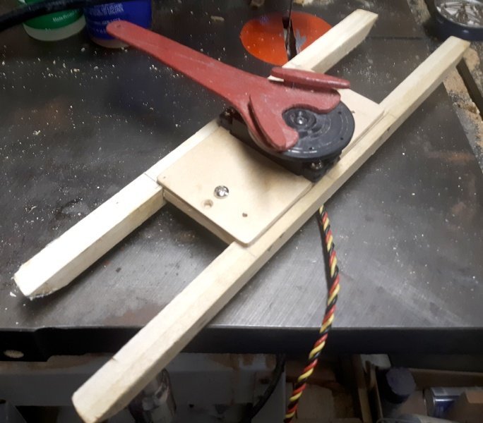
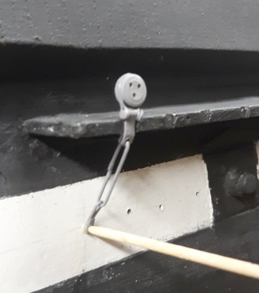
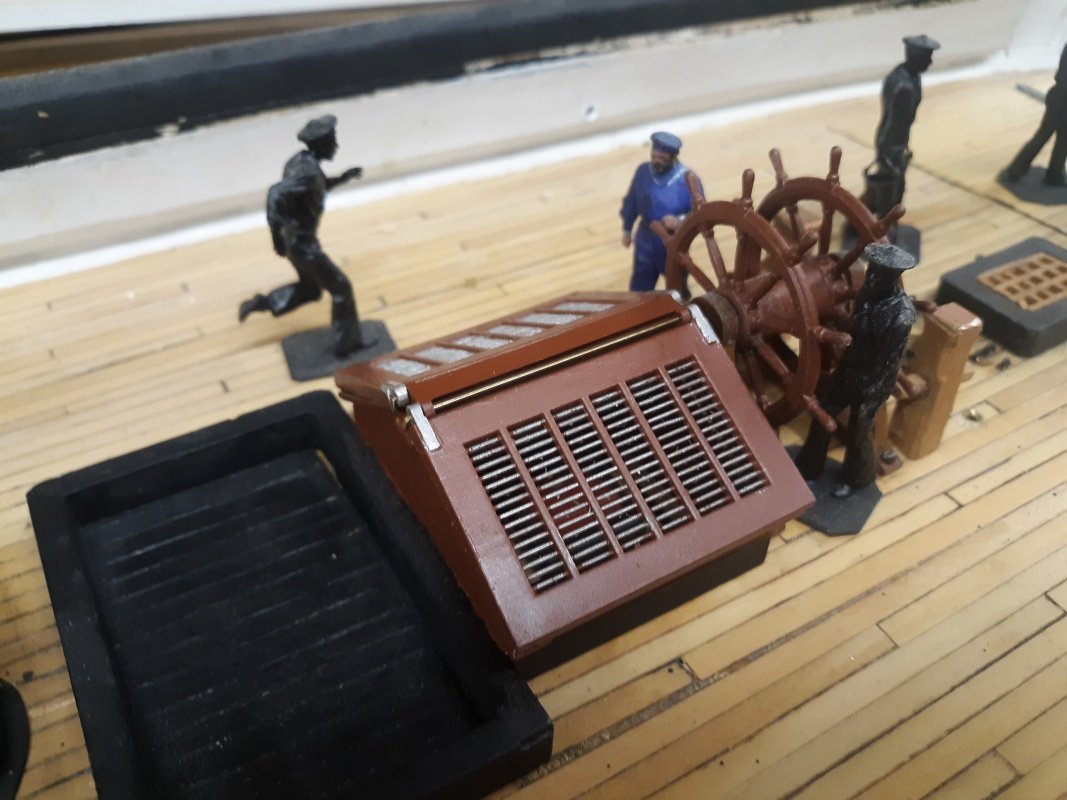
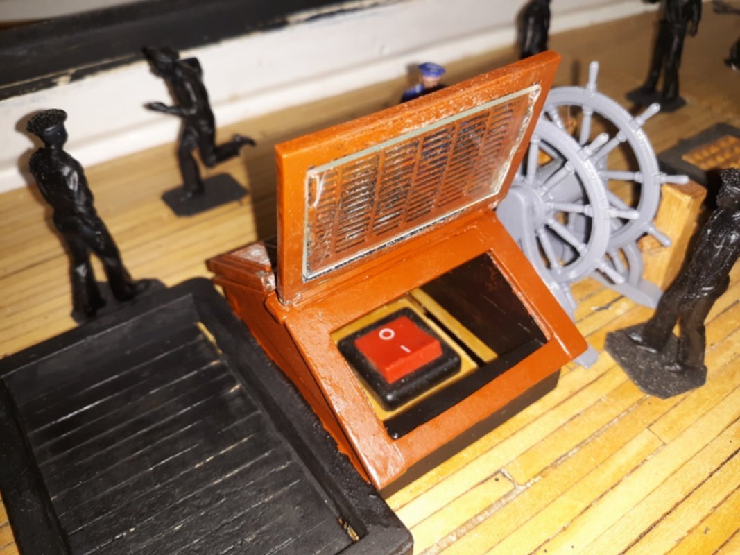
Just an FYI, so you don't have to dig back 30 posts or so... The red thing in the video is the arm on the servo, which is part of the radio-control system. It has 3 cleats on it, The white lines going into a hole in the end at the "bottom" of the arm are connected to the tiller on the rudder, which appears briefly at the bottom of the video. These lines run back to the two cleats at the "top" of the arm. Using cleats allows for relatively easy adjustment of the line. The cleat in the center of the servo arm, closer to the "bottom," is for the line that moves the wheel. Basically, the wheel is not directly connected to the rudder/tiller but the rudder and the wheel are connected to the servo. Anyone that doesn't get that explanation, say something and I'll try again.
- 553 replies
-
- 2
-
-
- sloop of war
- constellation
- (and 3 more)
-
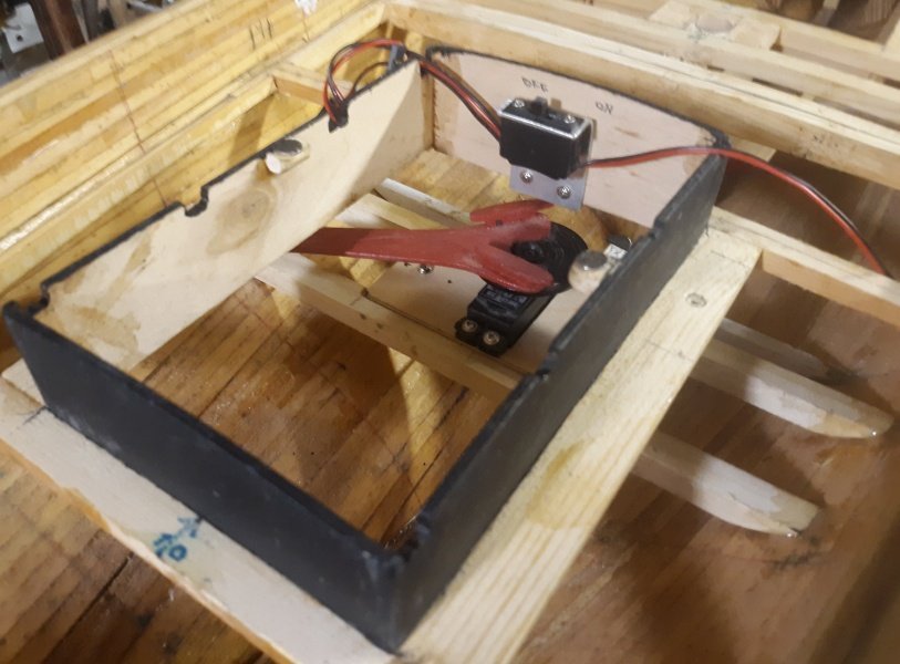
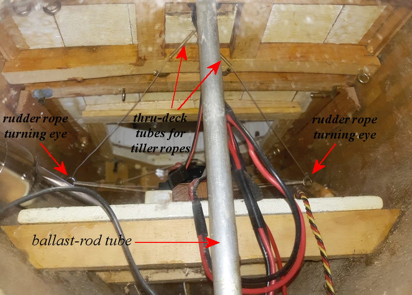
I'm no contortionist, but I finally managed to retrofit tiller ropes to the wheel so it moves with the rudder. The lines that connect the tiller to the servo run through cup-hooks mounted in wood blocks epoxied to the inside of the hull. Another eye with a brass pulley will get mounted in the block for the lines from the wheel. Right now they're sharing cup-hooks with the servo lines. The video is taken from astern through the aft access hatch. con20220609b.mp4
- 553 replies
-
- 7
-

-
-
- sloop of war
- constellation
- (and 3 more)
-
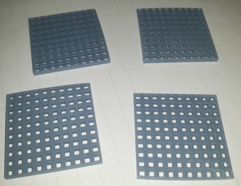
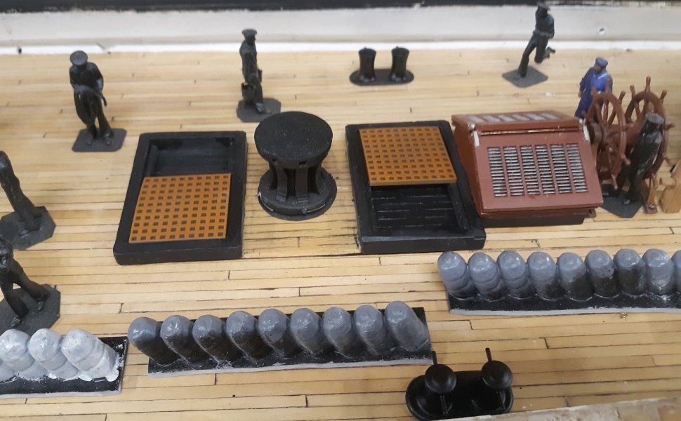
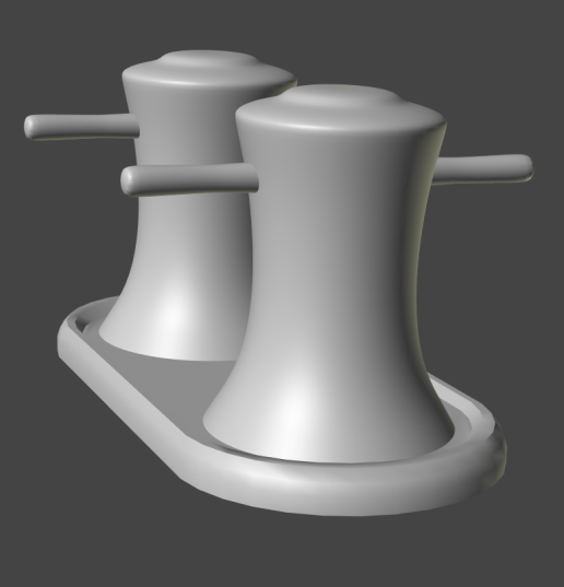
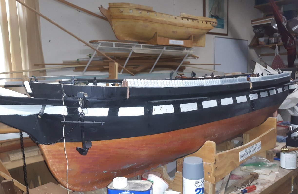
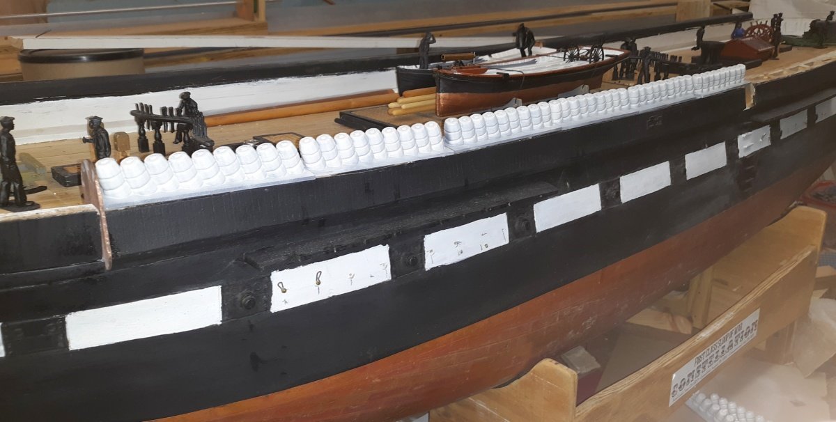
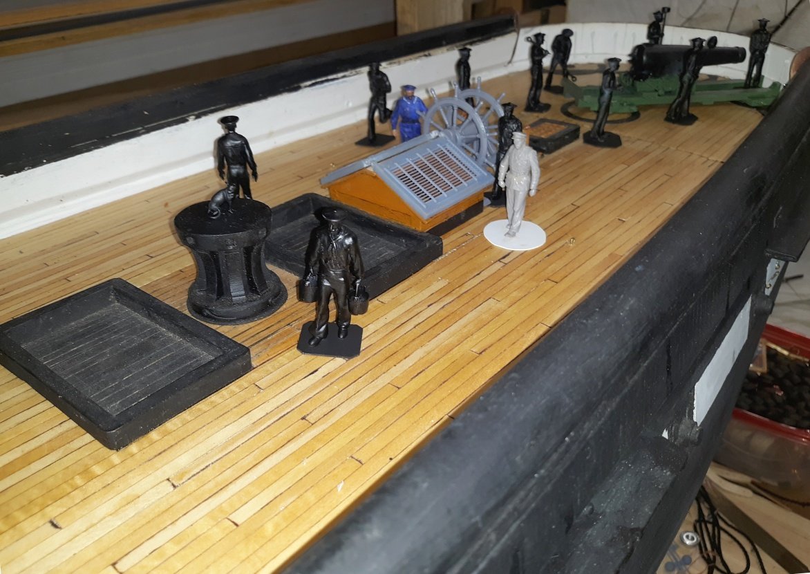
Printed some gratings and placed them in the companionway hatches at the capstan. Printed some gunport eyebrows and installed them on the portside. The hammocks are all glued down, so the hull was turned to work on the starboard side. ...and the old eyebrows I started installing were removed along with the balsa that capped the bulwarks. The new eyebrows got installed and a coat of paint. The brass square stock came in, so the out-board stuns'l irons got installed. Finally found paint that wasn't priced like perfume, and ordered a few jar, including Olive for the pivot guns. Loaded up the airbrush and got to work...
- 553 replies
-
- 5
-
-
-
- sloop of war
- constellation
- (and 3 more)
-
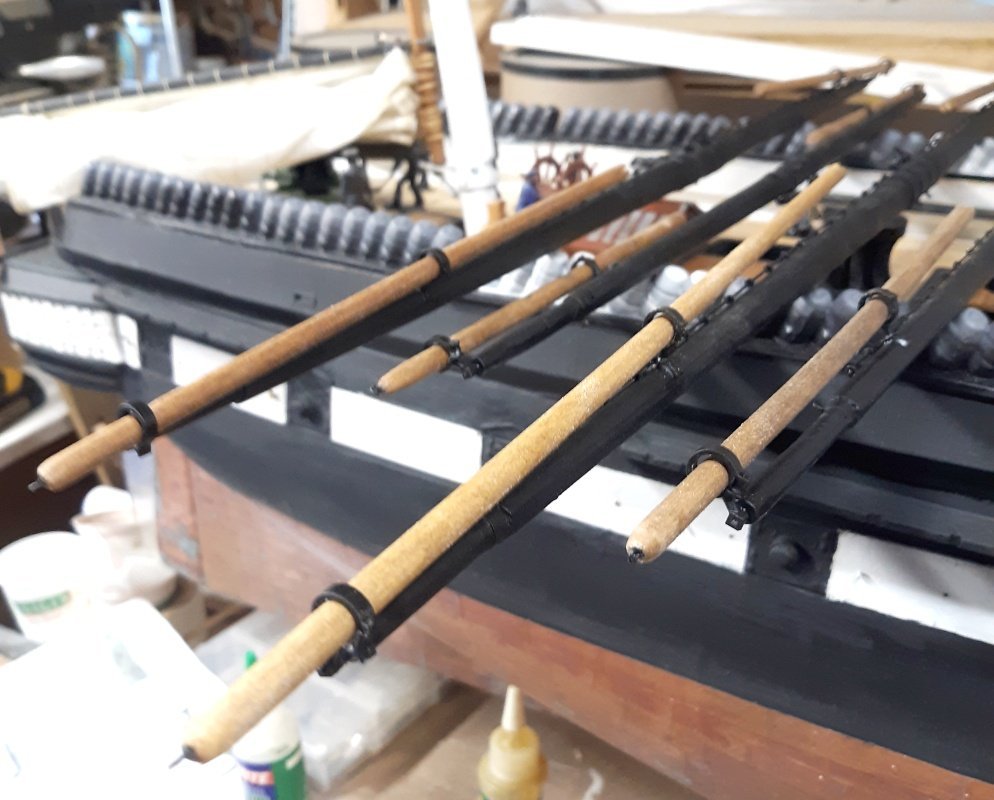
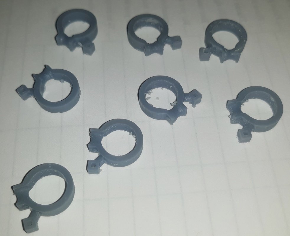
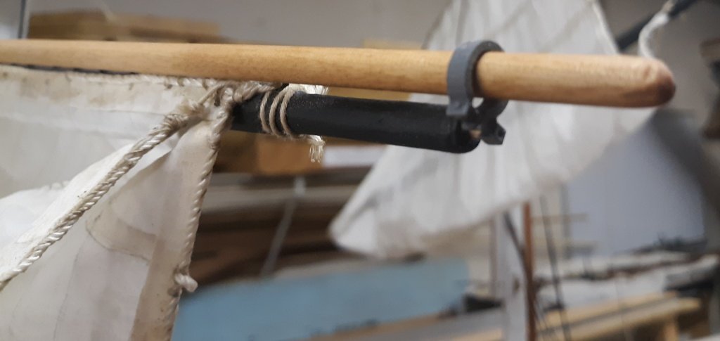
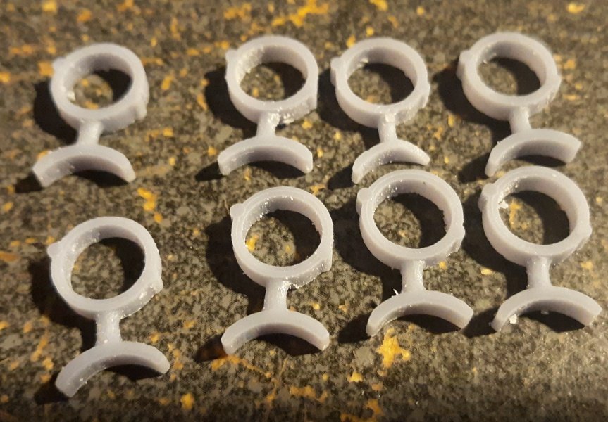
A couple of pieces failed to print, so I printed another batch to make up the loss and have some spare parts if needed. The stuns'l boom sits better on the yard with the adjusted fittings While those parts were printing, I started making up the top rails, which are going to require making some netting for them.
- 553 replies
-
- 4
-
-
- sloop of war
- constellation
- (and 3 more)
-
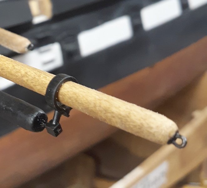
It's basically a pin sticking out of the end of the yard, and with the iron fitted, it'll have torquing pressure on it, which I don't think would survive the mildest bump. I used a bit of bamboo skewer to test fit everything, and found I needed to tweak the models a bit. I lengthened the, um, stalk? on the outboard fitting, and shortened it on the inboard one slightly. I also adjusted the thickness of the outboard iron's hoop to match the inboard one. The whole group of eight sets will take an hour and a half to print.
- 553 replies
-
- 3
-
-
-
- sloop of war
- constellation
- (and 3 more)
-
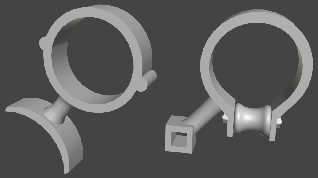
I modeled and printed the stuns'l boom irons, both inboard and outboard. I didn't make the inboard ones functional (hinged). Now I have to find or make some brass square stock for the ends of the yard, which is turning out to be more difficult than I thought. Hammering round into square is too uneven, so I'm gonna try grinding/filing it square next. The bitts got another coat of paint and some matt clear coat... and I started gluing down the hammocks, though the photo doesn't really show anything different. The bases will be painted black, and the hammocks the canvas color visible on the forward-most sets. Any gaps will get puttied, and the seam, inboard and outboard, will be covered with a mahoganyish wood strip. The big deal with 3D printed parts, resin ones in particular is they are created by curing resin with UV light. On a model that will be outdoors, naturally occurring UV will cure them more. making them brittle. Everything needs several coats of paint, and a UV resistant coating of clear-coat.
- 553 replies
-
- 3
-
-
- sloop of war
- constellation
- (and 3 more)
-
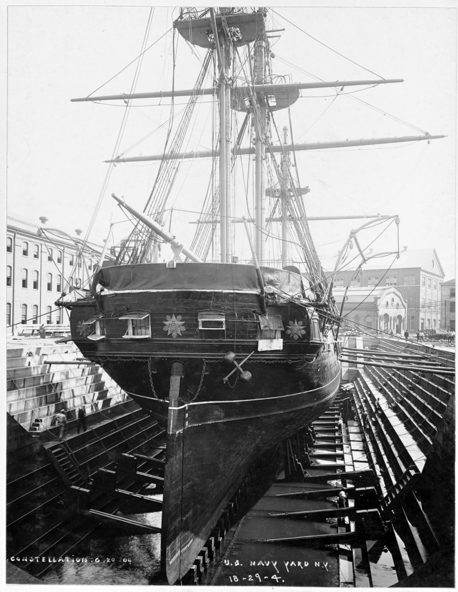
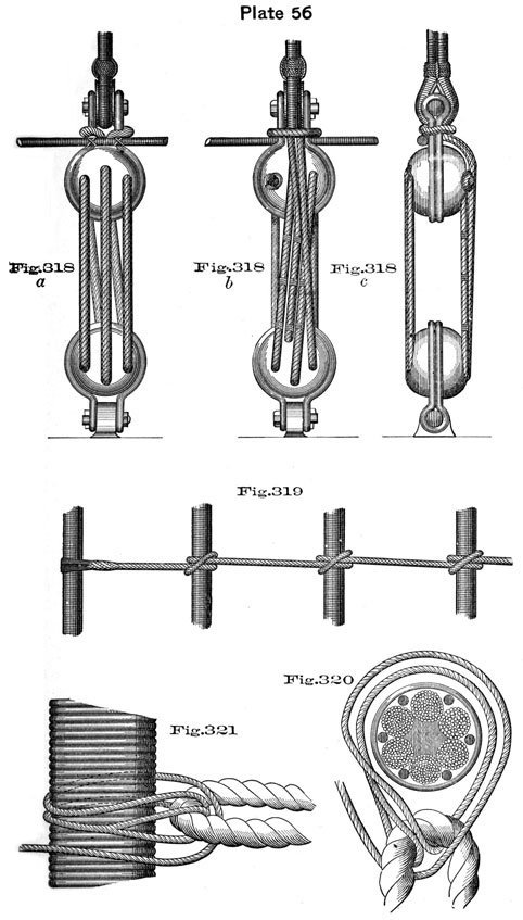
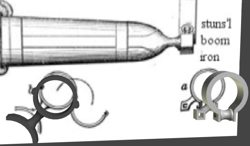
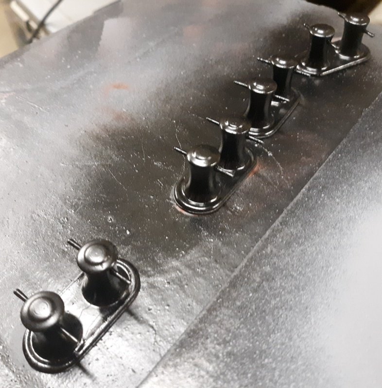
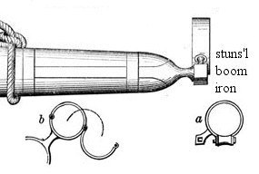
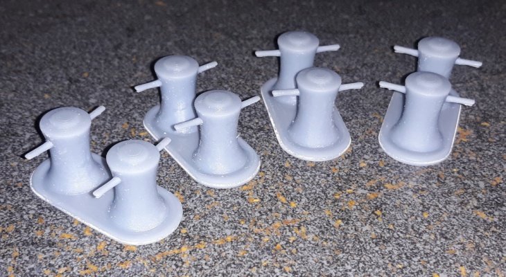
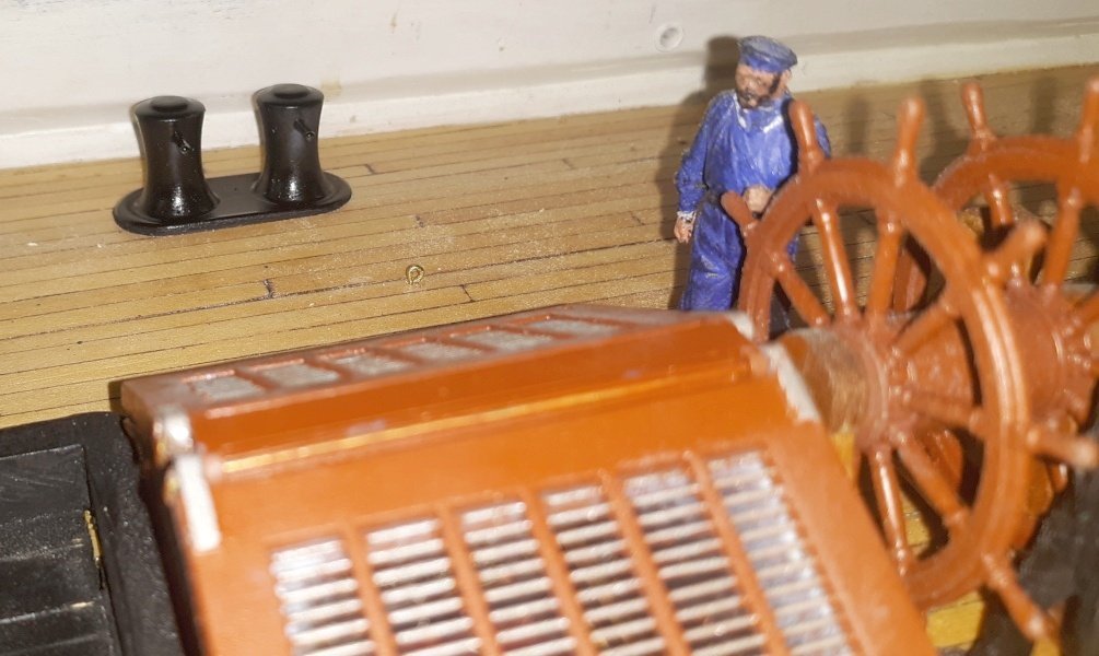
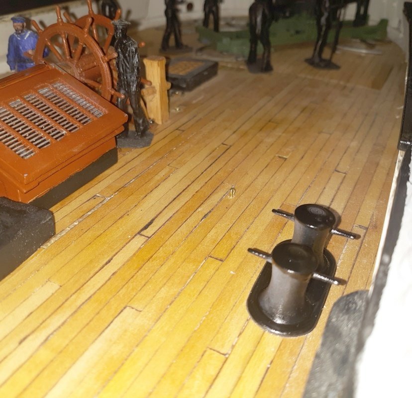
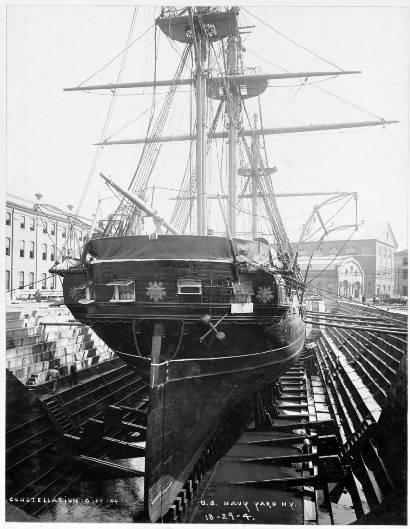
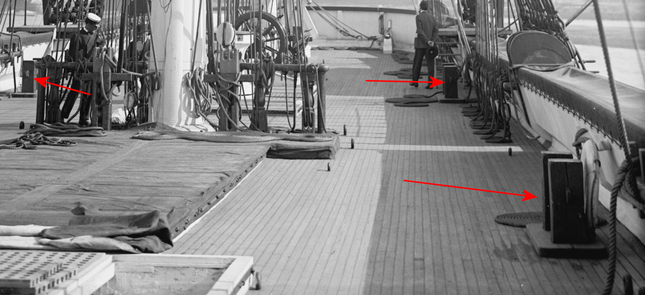
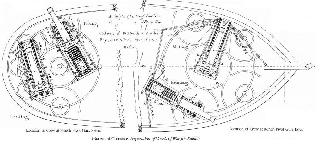
So, I got the COVID, and for about a week I basically had the flu and didn't feel like doing much of anything. Now I can focus and do something without dozing off, so it's back to work... The sky light wouldn't close well, so I remade it, also putting the bars in the sash instead of on it, so it looks like the photos now, and closes better. Then I found a site with a lot of Constellation images, some I'd never seen, some in better resolution than what I already had. I also found a better quality image of another deSimone painting of the ship which the site says was done in 1860. I still haven't found a color version. (remember to click the images to see them full size). They also had this pic of the ship in drydock in New York in 1904 with one of those night life buoys dangling and the other one missing. Looking through the images that showed the deck, I tried to figure out the four sets of bitts. The 1884 spar deck plan shows round ones with pins sticking out athwart-ship. In the photos before 1914 they appear to be cast-iron, painted black, and shiny. When the ship was spiffed up for the 100th anniversary of the War of 1812, it seems the iron bitts were gone or removed, and square wooden ones were put in, to look more old-timey I suppose. I have no idea what she had before the 1880s - even looking for them on other ships in Civil War photos, so I modeled the iron ones. Printed four of them and painted them, I held off gluing on the hammocks because I though I needed to install hawse-holes near these bitts, but there weren't any. In images of the ship tied to a dock or with another vessel tied along-side, the lines go to the gundeck. Also, I couldn't find any image where something is tied off to any of these bitts, iron or wood. I'm thinking they were actually more of a fairlead to turn a line so a gang could walk it down the deck, like the tops'l halyard maybe? Next up is a shot at making stuns'l yard irons. I think this resin is up to the job, and if one does get broken, it's no big deal to print another. I wish I could print the chain-plates with deadeyes and such, but I'm sure that would be asking way too much of this resin's abilities. I'm just modeling part a in the diagram. The hardware at the end of the yard will be done in brass.
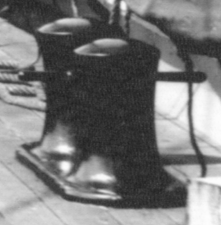
- 553 replies
-
- 5
-
-
- sloop of war
- constellation
- (and 3 more)
-
finding a R/C Napoleonic warship kit?
JerryTodd replied to Ian B's topic in RC Kits & Scratch building
Specifically, there are no "kits." Steel, Chapman, & Hutchenson (SC&H) used to manufacture large RC kits of a Baltimore Clipper, Brig, and HMS Surprise, but they closed down just before the pandemic. I'm not aware of anyone offering kits of RC square-riggers, much less Napoleonic period warships. Any such RC models you see now will have been scratch-built, or conversions of static models. The Heller Victory plastic kit is a common subject for conversion. I've converted three Revell 1:96 scale plastic kits to RC (2 Constitutions, 1 United States) myself over the years. I've seen a few wood kits converted, but they tend to be much more expensive than plastic kits for folks to want to risk them in the water. Most wood kits I've seen converted were completed, or nearly completed kits gotten cheap or free, and then retrofitted to RC. Your "signature" lists a Vanguard kit in progress. I imagine you have enough data in plans and patterns from that kit to reproduce the model again. If you want a sailing model, rather than a motorboat with sails, you can see how several folks have concocted controls for their square-rigger models here: Catalog of RC Square Riggers (note: the website no longer exist and the link's been removed. My Macedonian is a Napoleonic era frigate that's RC) Also, check this out here on MSW: -
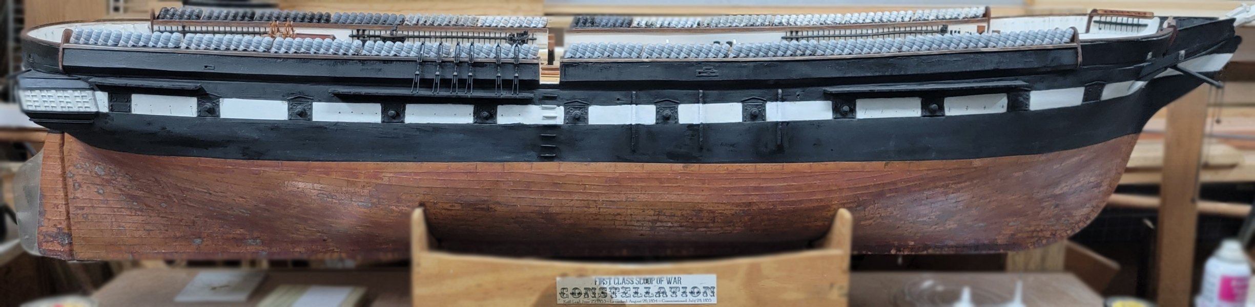
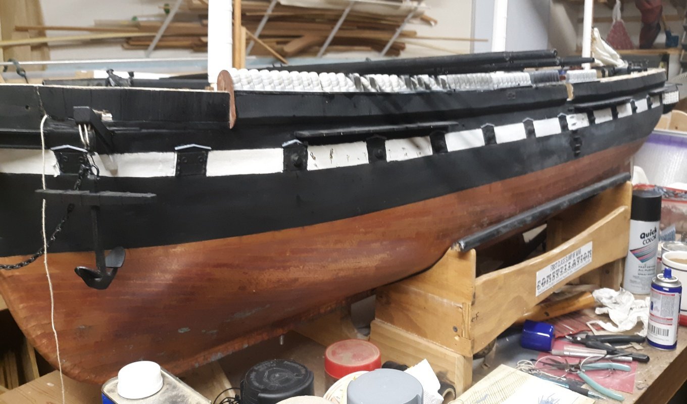
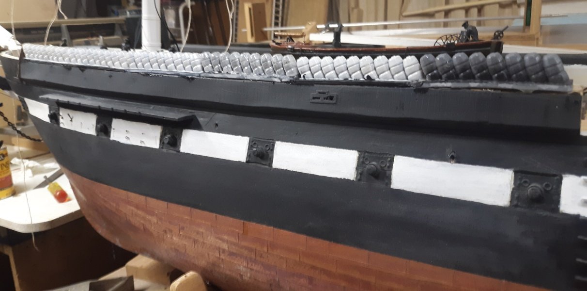
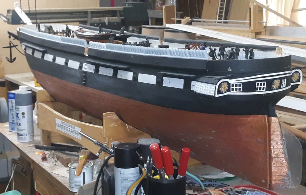
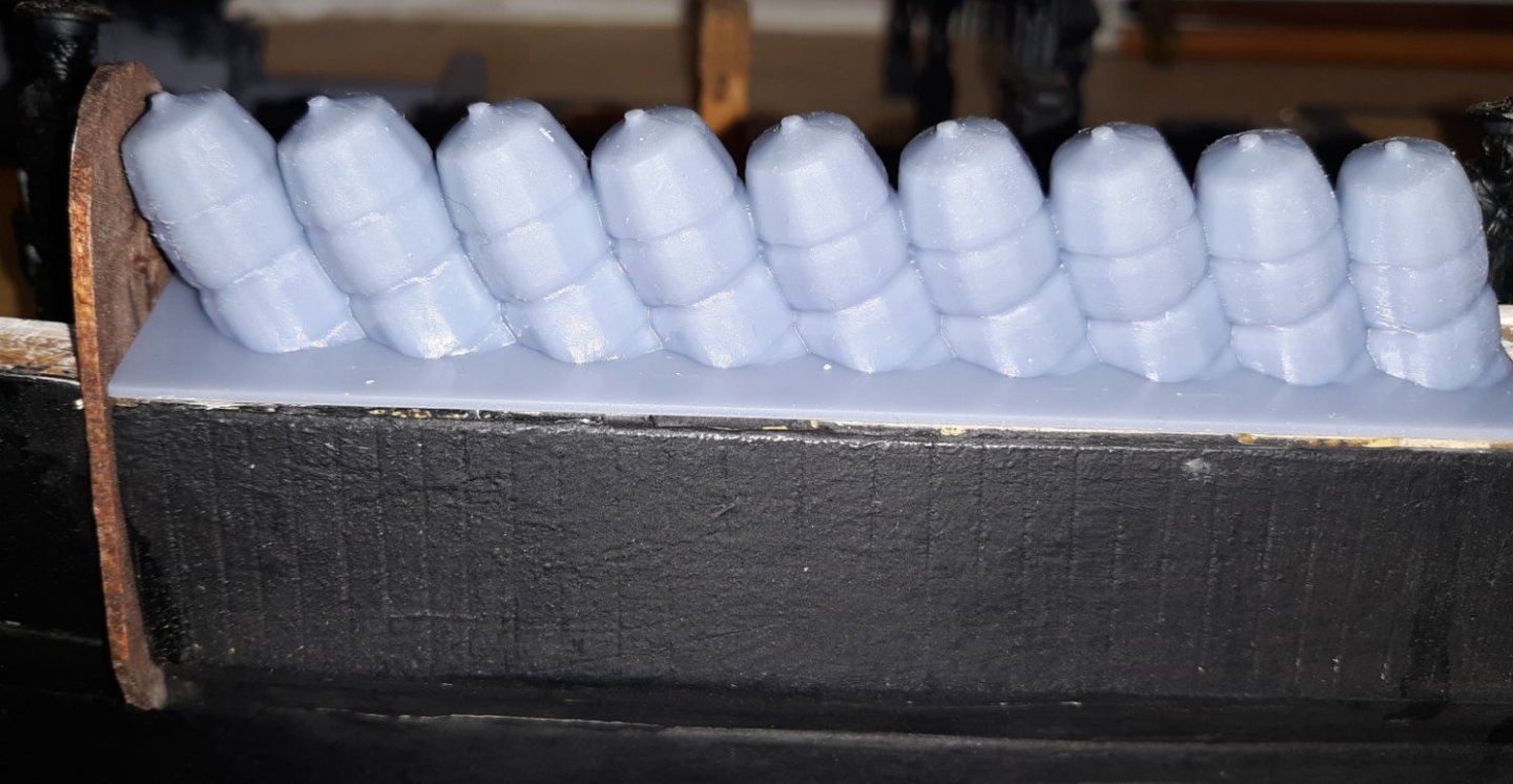
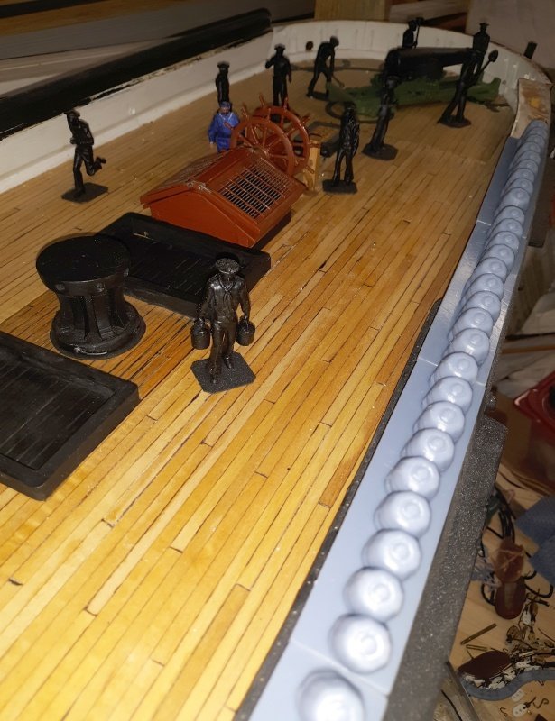
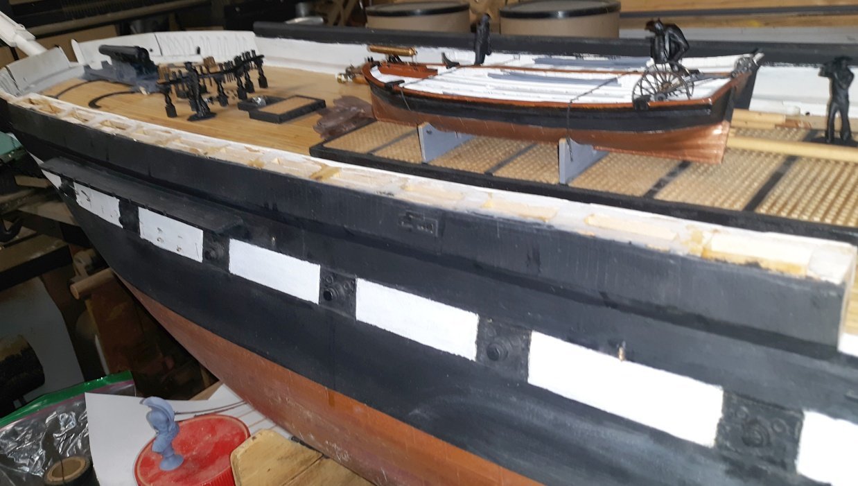
Printed the last section of hammocks today. Now they have their bases trimmed to the bulwarks and get primed, and painted. I have a couple of through-bulwark items to do before gluing these on, and I have to figure out what glue to use. I'm basically gluing plastic to wood, so I think the only real choice is epoxy. I have some slow-setting epoxy and I think mixed with some very fine sawdust from the band saw or sander will double as a filler/putty. Here's the model in the yard with the port-side hammocks sitting in place. The starboards are sitting on the deck because I have taken off the balsa on that side yet.
- 553 replies
-
- 4
-
-
-
- sloop of war
- constellation
- (and 3 more)
-
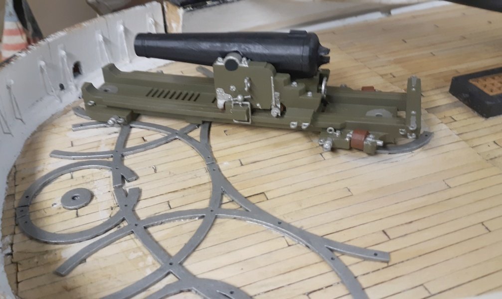
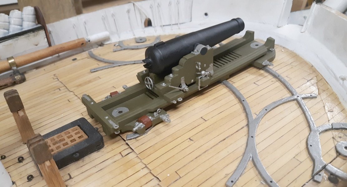
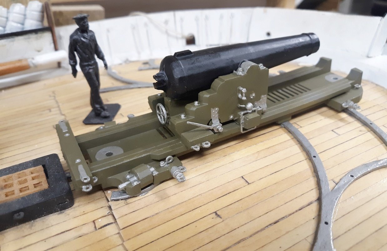
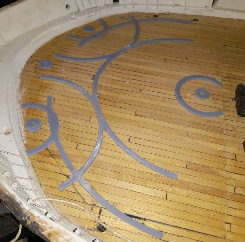
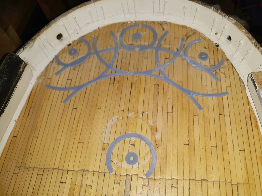
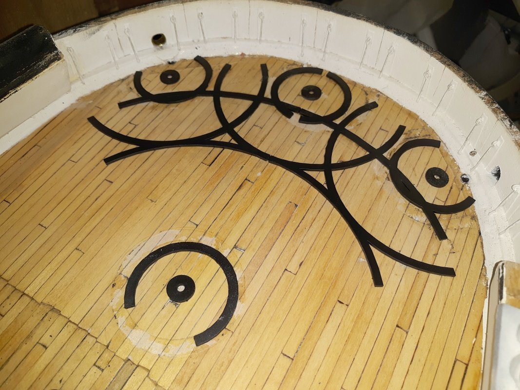
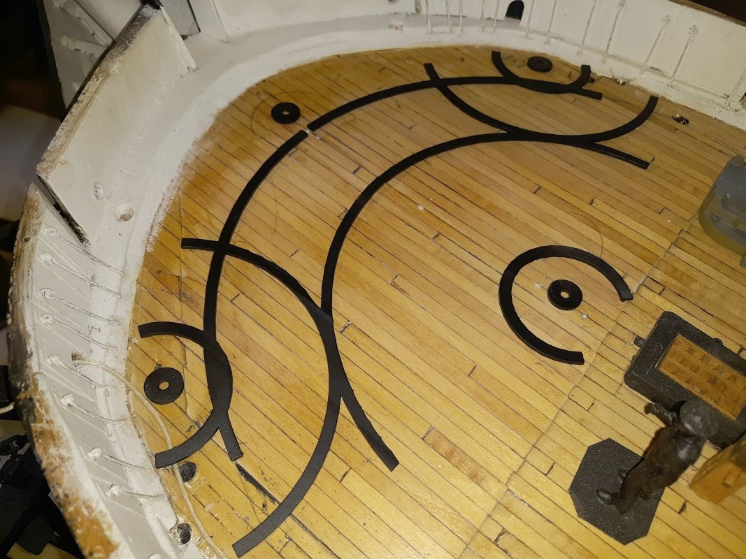
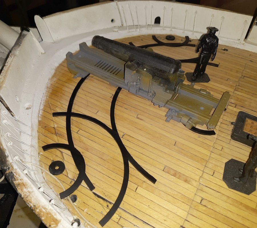
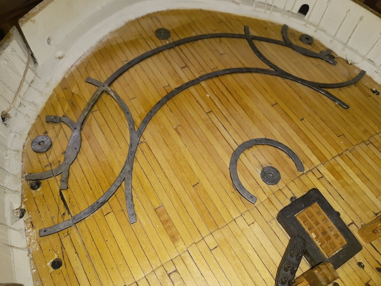
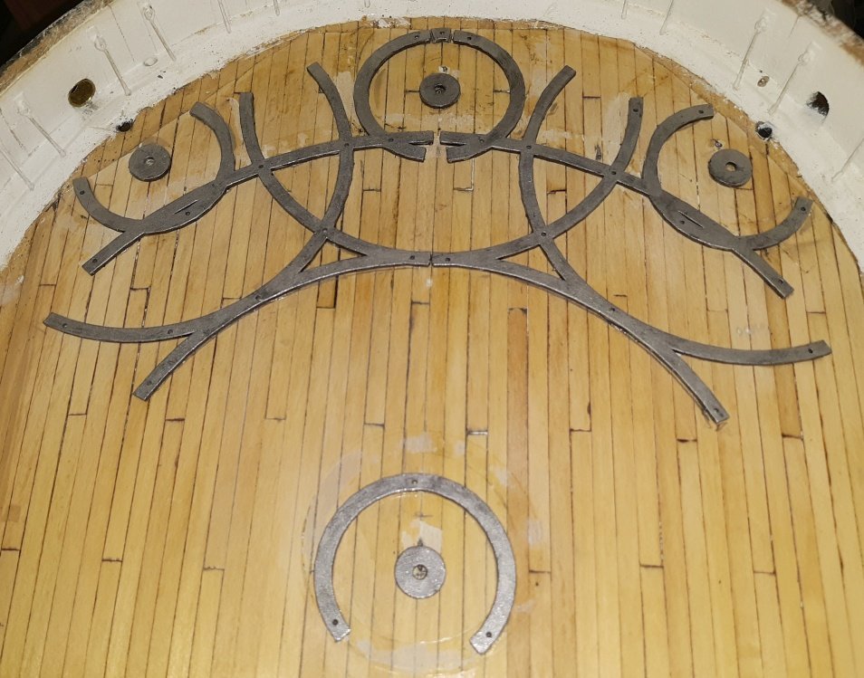
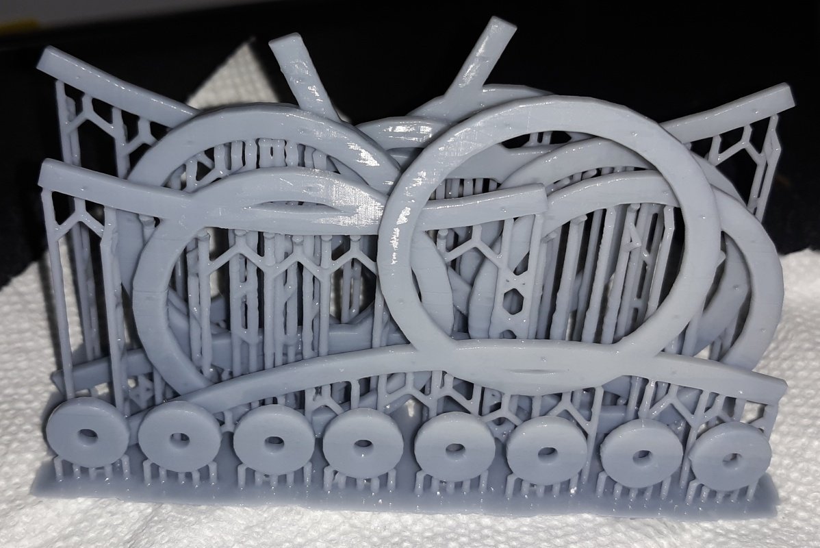
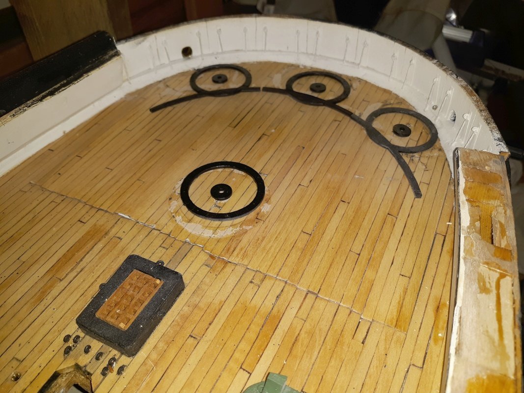
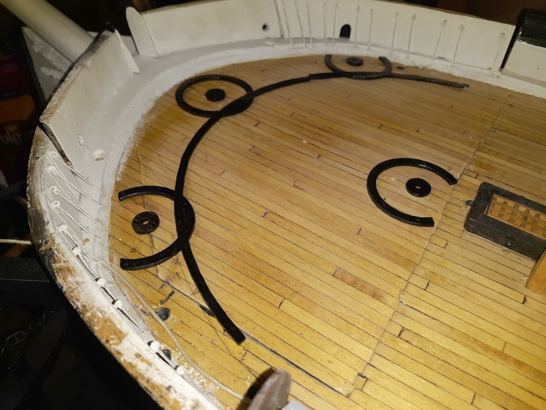
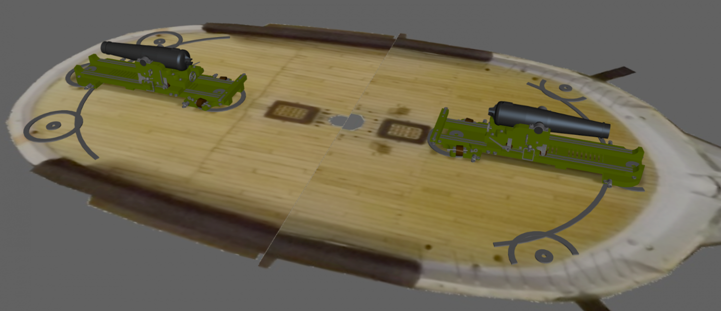
The part for the printer showed up and after installing the upgrade, I printed the new gun circles. Checked them for fit, and painted them. Not pictured, I drilled mounting holes in them and gave them another coat of paint. I have to clean the decks of the residue of the old deck circles, before I glue these down and then trim them to the hatches (the guns sit on access hatches in the deck fore-and-aft). Besides CAing them to the deck, I think I'll drill into the deck a little, countersink the holes I just drilled slightly, and fill each holes with a bit of epoxy. I'll probably give them a silver-black wash as well, to make them look more like iron. Fresh off the printer check for fit With some paint Gun and guy for scale Jet black just didn't look right, so I went surfing for photos of gun circles to see what they looked like; shiny, clean, rusty, etc. On active ships it looked like they kept them bright bare metal and probably greased them periodically. They looked black in some images but I think that was the shine during a sunny day, as there were sharp shadows in those photos. So I dug out the Testor's "Steel" paint and went to work, then carefully CAed them to the deck access hatches. The bow circle run off the hatch in a couple of placed, so they were trimmed to the edge of the hatch and cut-offs glued to their place on the deck, and the paint touched up. Bow circles alone, and with the gun. Stern circles alone, and with the gun. Now those parts of the deck need some more clean-up and clear coating.
- 553 replies
-
- 4
-
-
-
- sloop of war
- constellation
- (and 3 more)
-
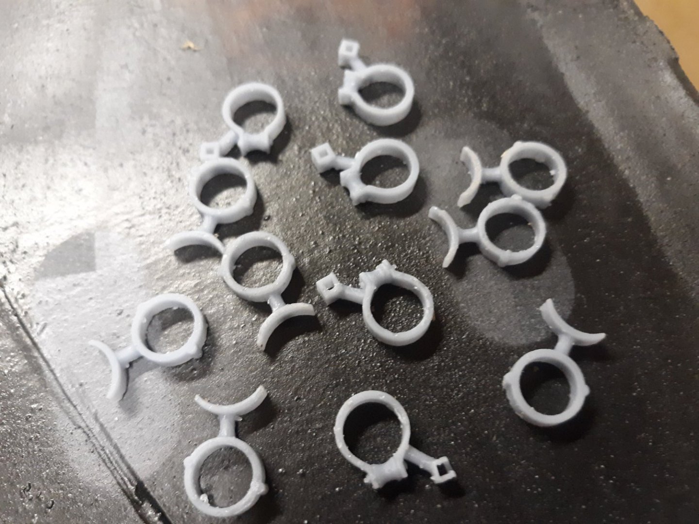
Still waiting for the new LCD to get back to printing again... but doing a little 3D modeling in the meantime. As mentioned, I added the rails for the center skid plate on the pivot guns. Still cleaning up the model, but this is about it. The bow is on the right, and the stern on the left. The bow has two firing positions, the center position doesn't need rings as it's a stowed position, not a firing position.
- 553 replies
-
- 4
-
-
- sloop of war
- constellation
- (and 3 more)
-
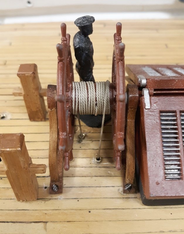
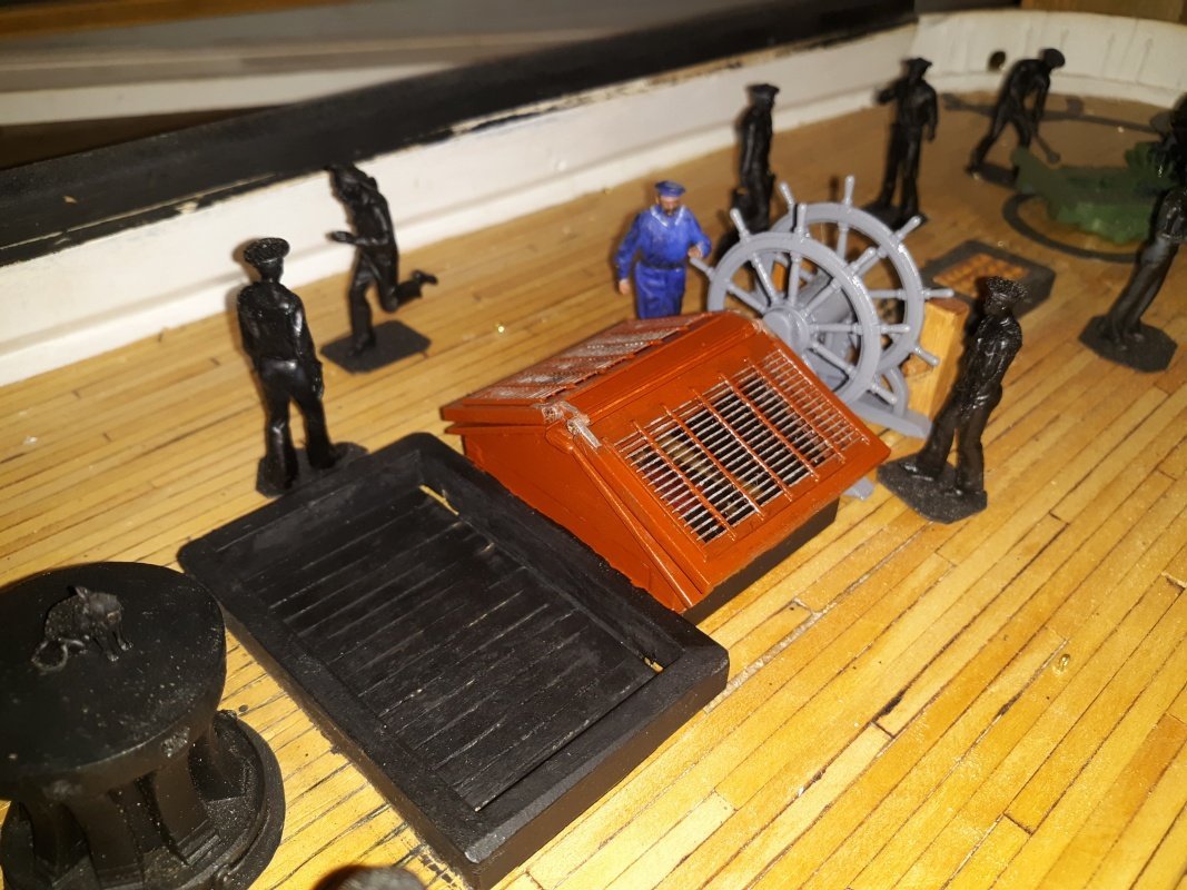
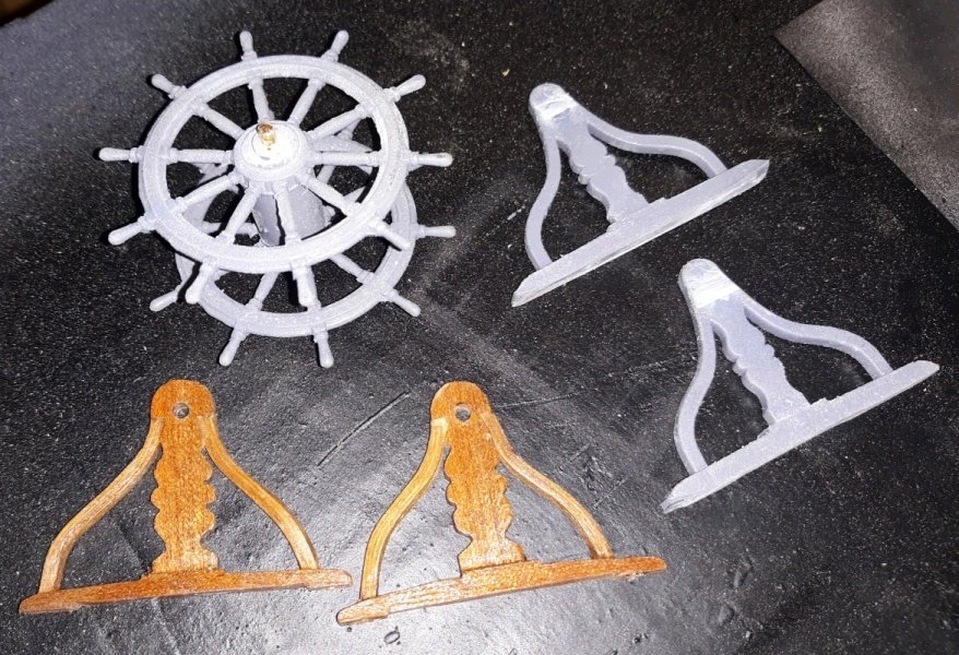
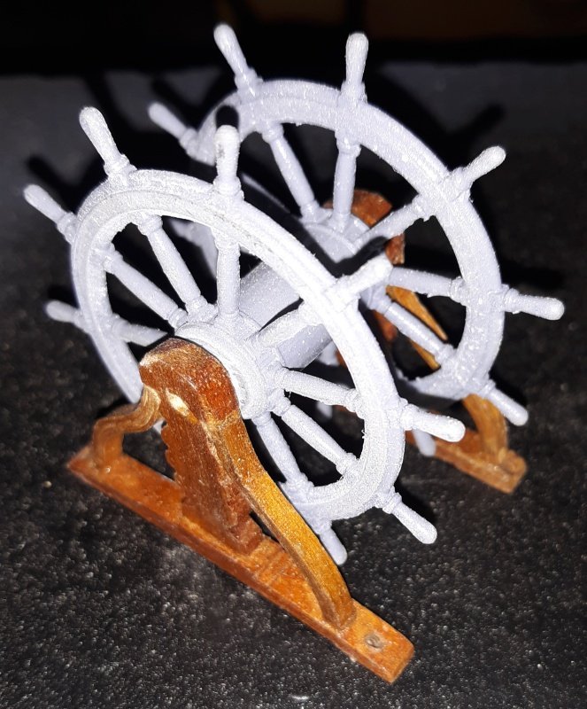
I was going to paint the new wheel but decided instead to reuse the wooden pedestal from the previous wheel. I sawed off the attached printed pedestals, drilled the drum and reused the brass rod axle. The skylight and the wheel got painted, and the wheel now spins. I'm going back to the idea of connecting it to the rudder servo so it'll turn when the rudder moves. I modeled the hammcks so they were hollow, saving a lot of resin/money and some weight I modeled the gun circles to be cleaner versions of the hand-cut one I had. I printed them all in one go, cleaned them, drilled them (to pin them to the deck), painted them, and they look great, but I think I'm going to add to it, more like what's shown in the manual, with rails for the center skid, etc.
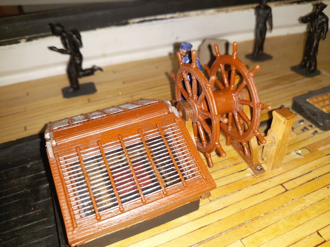
- 553 replies
-
- 4
-
-
- sloop of war
- constellation
- (and 3 more)
-
Looking back at this thread, I see I missed responding to your question Roger, I'm very sorry, it doesn't normally take me almost a year to catch on, then again, maybe now it does. Constellations boat lengths were; Launch: 31 ft at 1:36 scale: 10.3" 1st Cutter: 28' 7" - 9.5" 2nd Cutter: 25' 10" - 8.6" Quarter boats: 26' 6" - 8.8" Stern boat: 28' 2" - 9.4"
- 553 replies
-
- 1
-
-
- sloop of war
- constellation
- (and 3 more)
-
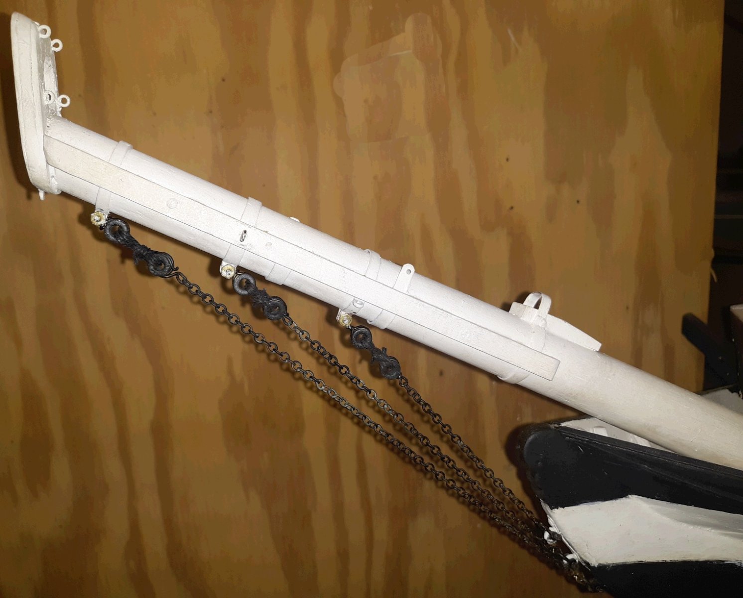
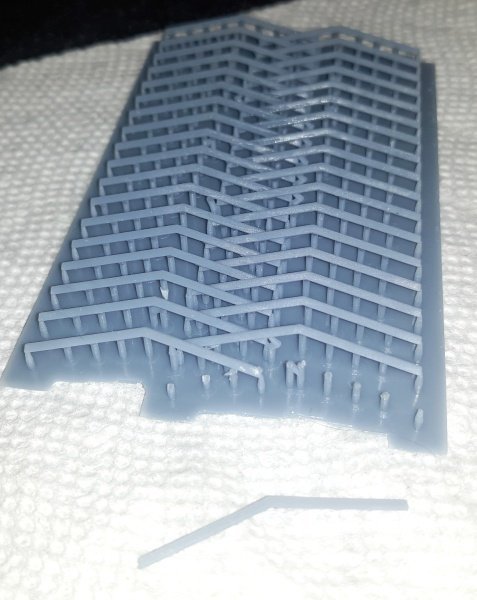
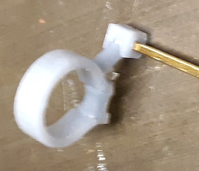
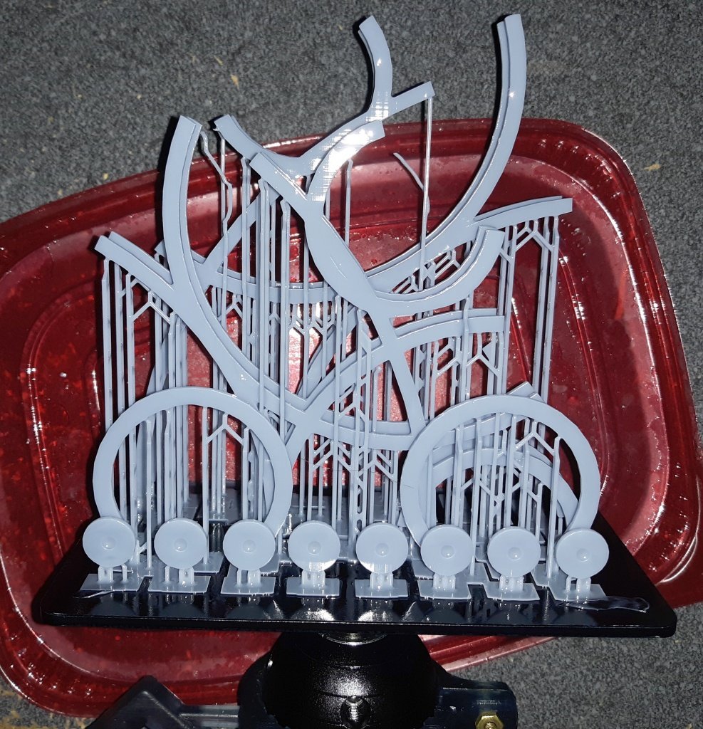
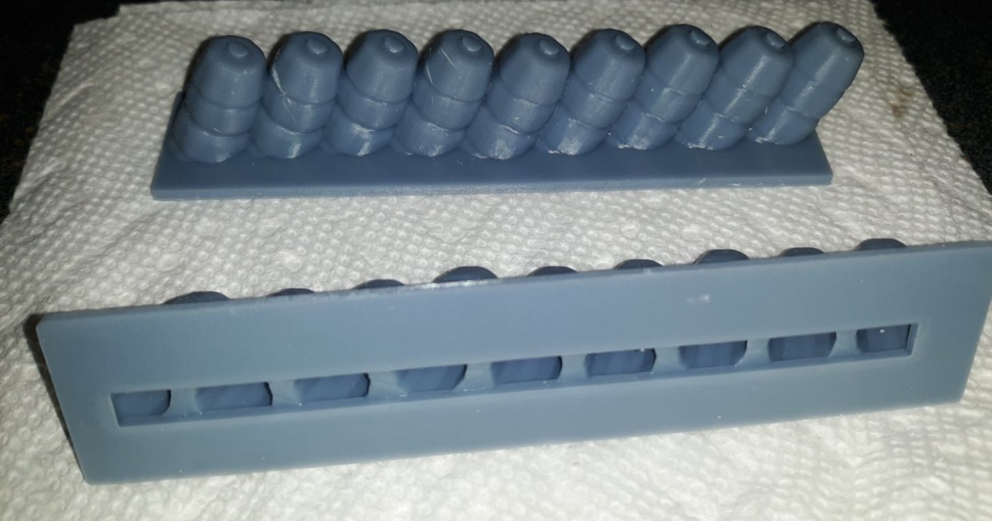
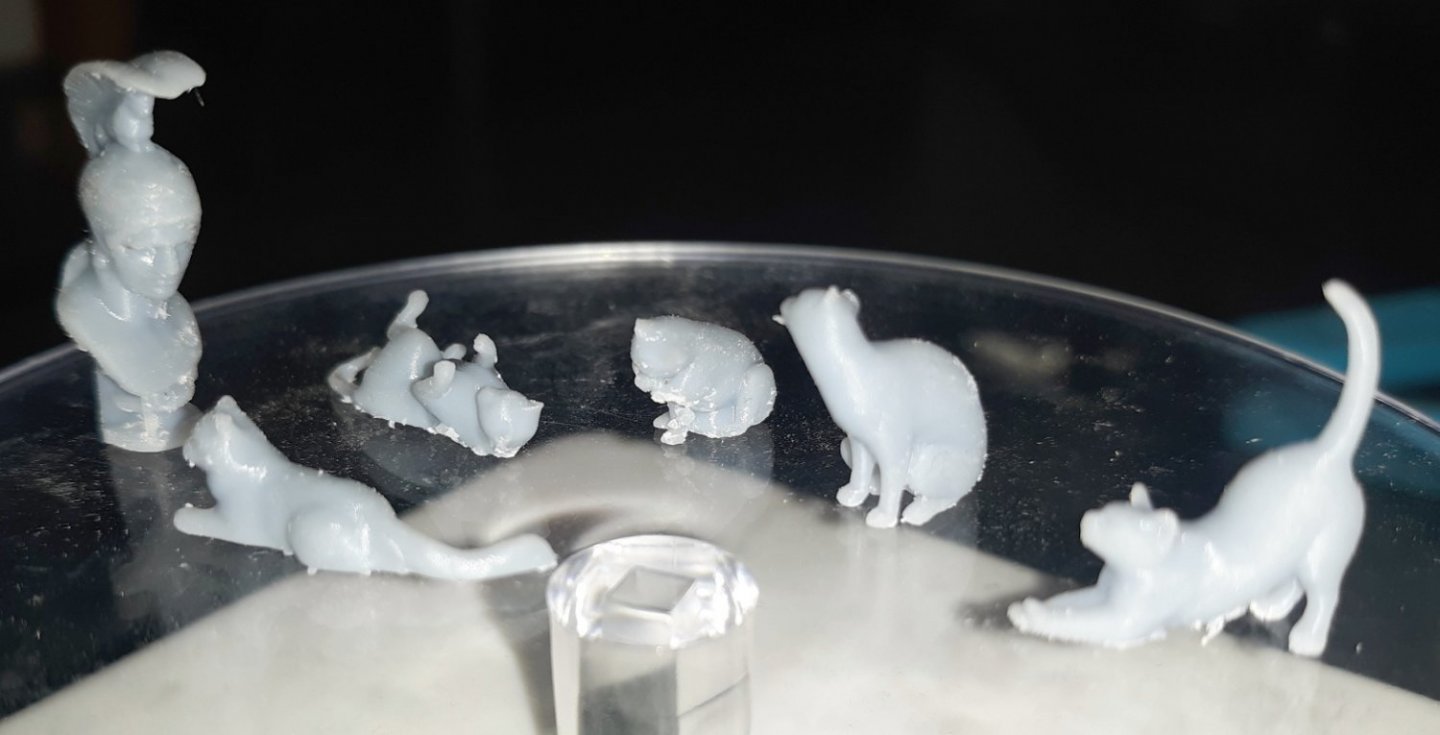
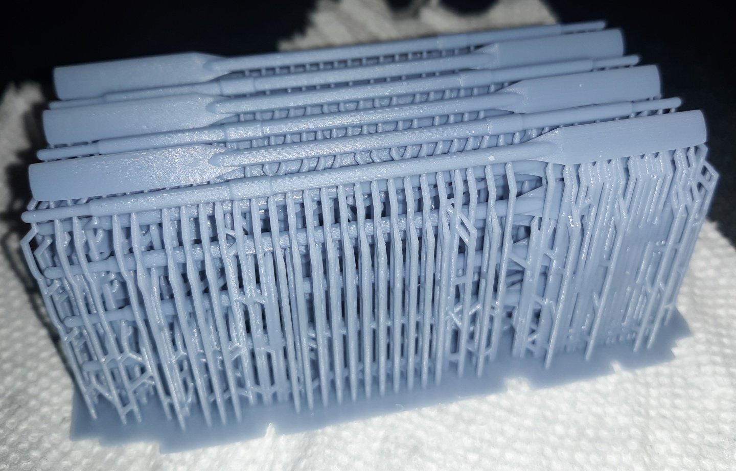
The LCD screen on the printed went bad and I had to get a replacement. With that done I stuck some things together to give it a test drive. I plan to put a second cat on board, and here are the one's I have to choose from (excuse the bust of Ares). The one rolled on it's back, and the stretching one with the tail in the air are the ones I'm leaning towards. I rigged up the bobstays with the new bulleyes. The crew got a base-coat of black in prep for painting them to look like, well, crew. The new skylight sashes are mostly installed. It all needs to get painted to match the rest of the skylight, and the glass installed to be considered done. I worked on the 3D model for the hammocks, but it's a little low-res and looks too faceted when printed. I'm going to model them in groups to be glued down on the bulwarks in sections of about 11cm each (that's what fits on the printer). In every image of the ship I have, she has her hammocks showing with out tarps covering them. I originally planned on modeling them from some combination of materials, making a mold, and casting them in resin so I wouldn't have to worry about them getting damp, growing moldy, leaking, causing rot, etc, on a working, sailing model. Making them in 3D though, I need to make them hollow so they don't use up so much resin. In the pic, I removed the rounded over layers of balsa on the port side. You may have noticed in previous pictures the line between the black and white of the inner bulwark was, well, sloppy; that's because I never intended the balsa cover to be permanent. So, if you'll excuse me, the thing below that looks like an electronics cooling component just came off the printer and contains 48 10 foot oars in 1:36 scale, that I have to carefully dig out of there


- 553 replies
-
- 3
-
-
- sloop of war
- constellation
- (and 3 more)