HOLIDAY DONATION DRIVE - SUPPORT MSW - DO YOUR PART TO KEEP THIS GREAT FORUM GOING! (89 donations so far out of 49,000 members - C'mon guys!)
×


AON
-
Posts
2,866 -
Joined
-
Last visited
Content Type
Profiles
Forums
Gallery
Events
Everything posted by AON
-
 Like pry bars. Slipped under the gun and pivoted on the step of the carriage to lift the weight off the wedge. Makes sense. How would the gun be trained left or right when the trunnions are locked in place?
 -
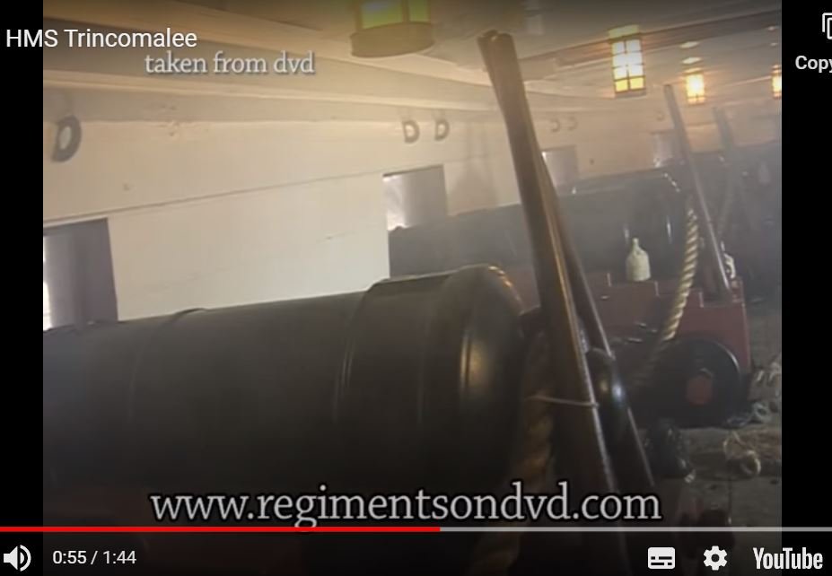
I stumbled across a video of the restored HMS Trincomalle and noticed two pieces of wood stood off the gun carriage, In a reverse V shape, resting against the castobell of the gun, lashed to the rope with "small stuff" (very light line). Does anyone know the purpose of these?
-
paperdrawing transfer to cad
AON replied to helge's topic in CAD and 3D Modelling/Drafting Plans with Software
I am making sawdust at the moment. Will have a closer look in an hour or two. Possibly Vahur will respond also. -
I admit to having done everything you wrote above. So you are not alone! I've watched that same video and I've looked at a number of builds and have not seen them.
-
It is always the last place you look! You mentioned a contract... I finally went to look at my transcription for my build, and there it was with the definition added below (I did this a number of years ago). [Page 12 - HMS Bellerophon] STANDARDS ---- To have 12 standards on each side of the gun deck, the wood sided 12-1/4 inches; the foremoft (foremost) pair, and as many of the others, to be iron, as shall be directed; the up and down arm to reach the upper edge of the upper deck clamp, the other 4 feet 3 inches long, bolted with 7 bolts in each, of 1-1/4 inches diameter: the standards, both wood and iron, shall be all fayed on shoals of 3 inches plank, laid with tar and hair, or old canvas; to have a standard on the gun deck, against the head of the stern post, sided 13 inches, the fore and aft arm to be of fufficient (sufficient) length to receive a bolt in the third gun deck beam from abaft, to be fcored (scored) down on the gun deck beam 2-1/2 inches; the up and down arm to reach the upper side of the helm port tranfom (transom), and to have a carling from the beam abaft the mizzen maft (mast) to the tranfom (transom) 13 inches fided (sided), fcored (scored) up between the beams; and that the space from the lower side of the knee to the upper side of the carling, be filled up by fillings, let down between the beams before the knee is fayed, that the faid (said) standard may be bolted by one bolt in each beam, and one bolt between each beam, by bolts of 1-1/4 inches diameter, and to be well clenched under the faid (said) carling: to have a standard on the gun deck, against the apron, fided (sided) 13 inches, the up and down arm 5 feet 9 inches long: the other to be long enough to receive a bolt in the fecund (second) beam from afore, and to be properly fecured (secured). I imagine most builds don't bother as, at the reduced build scale, they are so thin and (less the tar line) difficult to see.
-
Gary Thank you. I likely would never have found this.
-
Gary, I guess I was typing as you were posting! I related the purpose of this shole/sole piece to the pergola timbers I've mounted on the flat concrete cap on top of the brick columns in my back yard. I slipped a pieces of aluminum bar under the timber, on top of the cap piece, so when the snow melts the timber is raised slightly and can dry properly. Might have been over kill on my part but I was trying to avoid early rot as experienced in other wooden structures I've had over the years. I would appreciate knowing as much about this item as there is to be learnt (learned?).
-
Thank you Garyshipwright for the description from Fincham. I've looked in a half dozen of my books and a seaman's dictionary and have not found mention of the sholes/soles in this context. Also not shown in any diagrams/sketches. I guess it was too small a detail to be noticed? Does anyone have an image with this piece in it they can share? (Druxey?) I'd like to add it to the list of things I shouldn't forget... along with a map to find my list!
-
Did it simply lift the standard off the deck to keep it dry?
-
Your mini splices are impressive. As a sea cadet I was taught to roll my finished splices on the floor under the sole of my shoe to tighten it up. You might try this with a piece of wood on top to see how it changes things. On second thought, due to the reduced scale, possibly just rolling it between your thumb and forefinger 4 to 6 times might do the trick!
- 128 replies
-
- 2
-

-

-
- model shipways
- new bedford whaleboat
- (and 1 more)
-
you should start a build log for this!
-
There is a wonderful paper on the properties of wood at: https://thenrg.org/resources/Documents/articles/AnOverviewOfWoodProperties.pdf on page 8 is an image regarding shrinkage and warpage you might want to study it and then decide.
-
I always seem to stumble onto these beautiful builds too late! I made a note regarding your comment on bending maple versus boxwood in post #12. This is helpful info. I am also a fan of modifying the nose of wood clothespins to clamp in difficult spaces. Your long nose version in post #24 is something I hadn't envisioned and it will also be a handy addition to my collection. The wrapping of the tangs of the oarlocks with small stuff was something I hadn't seen before. I imagine it saved the oars from wearing prematurely rubbing against the harder metal surface. I do know that the holes at the ends of the oarlock tangs were to close the gap with waxed whipping (small stuff) so the oar would not bounce out in rough weather. In my limited experience (sailing and pulling 27 foot whalers and 32 foot cutters) the post of the oarlock had a hole also and small stuff was secured to it and the other end to riser (that the thwart rests on) so they did not get lost at sea. The line was long enough that the oarlock could be removed and stored dangling inboard. I can see in the sketch in your post #93 that yours had this hole. Your metal work is amazing, from the pail and barrel bands to the anchor! Then you actually did and eye splice in the bow rope! Thank you for sharing. I learnt quite a bit.
- 128 replies
-
- 2
-
-
- model shipways
- new bedford whaleboat
- (and 1 more)
-
paperdrawing transfer to cad
AON replied to helge's topic in CAD and 3D Modelling/Drafting Plans with Software
I assume you haven't used any CAD program yourself. Prior to someone offering to do work for any compensation they would need to see the drawing(s) to appreciate the enormity of the task to be done. Having done engineering drawings for clients for well over 30 years I can attest to having experienced the "what the client said. what the engineer heard. what the client wanted" phenomenon. It should be avoided or there will be a great disappointment for both parties. Mark is correct in the steps to do the work. Can you post photos of the drawing(s) you would like converted? -
Thickness Sander questions
AON replied to Ron Burns's topic in Modeling tools and Workshop Equipment
Bonjour Gaetan I have a combination disk and belt sander on my worktable. I've use both regularly, the disk for end sanding small pieces and the belt set horizontally for larger flat pieces. It has an option to flip the belt vertically. I've never done this. After reading what you posted I think I will give it a try and find out for myself what you are talking about. It will also give me an opportunity to clean under the belt! Thank you for making me wonder about it. I am open to learning. -
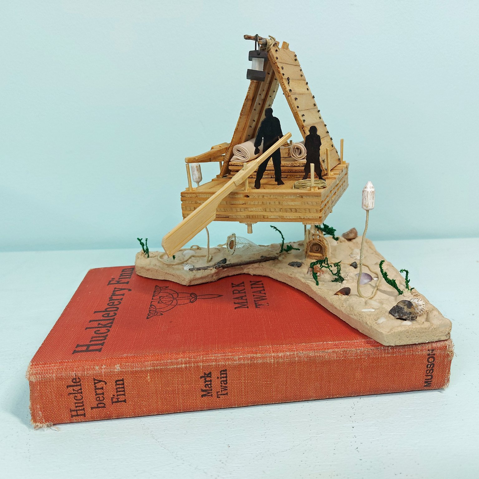
I had a couple good weeks of framing, followed by yet another needle in the left eye and a few days recovery. Then I decided to work on something different for a change of scenery. Always nice to do that occasionally, finish something completely for a change as you can only fool yourself for so long that having completed yet one more frame is a major achievement 8*) My Mississippi Plank River Raft (1830-1840) based on the description by Mark Twain in The Adventures of Huckleberry Finn. The raft hovers above with the riverbed below (on top of the book). Crayfish and shrimp traps on the riverbed with wooden buoys floating above on either side of the raft at the imaginary water level. Photo below. Just needs a display case and name plate. I was back onto frames yesterday.

-
Hope it comes back negative.
-
off to Tobago for a holiday ??? heck, if I were you I'd step outside and say I was there. (-5°C this morning up here) Just watched your last video! These are great. The pencil grout also seems like a winner. Good to hear you at the meeting on Saturday! Enjoy your vacation.
-
Stitching sails with sewing machine
AON replied to Jorge Hedges's topic in Masting, rigging and sails
matte medium
-
looks like Druxey hit send before I was done typing! The image he linked to will show what I was trying to explain.
-
Per TFFM Vol 1 pg 257 Hanging Knee - fore side in fore body and aft side in aft body that is to say hanging knees on forward beams go forward of the beam, and those on aft beams go to the aftside of the beam. They bolt on the side to the beam not underneath so as to help prevent the beams from racking. Lodging knees - aft side in the fore body and fore side in the aft body (just the opposite to the lodging knees otherwise they are on top of each other and that doesn't work very well) The lodging knee end (running along the inside hull not the beam) was stepped to locked into a notch in the top outside corner of the hanging knee. Hope you can understand this... that is to say that I hope I did a half decent job trying to describe it.
-
go here to post #148 for a picture of the rudder coat on HMS Victory modelshipworld.com/topic/21022-hm-cutter-alert-by-blue-ensign-finished-vanguard-models-164-scale/?do=findComment&comment=662384
-
Wood filler?
AON replied to Phalpenny's topic in Building, Framing, Planking and plating a ships hull and deck
Peter Not to name drop..... David Antscherl (in our local model club) once showed me that a dab of wood glue in the crack and a light sanding to move the sawdust into the glue made the crack disappear like magic. Of course, he has a magic touch, and years of experience! Try this on a test set up of two pieces of scrap before doing it on your model to see if it works for you. -
I think the caulking and treenails look absolutely fantastic!