
HOLIDAY DONATION DRIVE - SUPPORT MSW - DO YOUR PART TO KEEP THIS GREAT FORUM GOING! (89 donations so far out of 49,000 members - C'mon guys!)
×


AON
-
Posts
2,868 -
Joined
-
Last visited
Content Type
Profiles
Forums
Gallery
Events
Everything posted by AON
-

Need CAD type program
AON replied to Sambini's topic in CAD and 3D Modelling/Drafting Plans with Software
I was reading post #19 above and immediately thought of all the different things I use my 2D CAD program for besides drawings for ship models. You never stop learning, so I believe a steep learning curve is no excuse if creating computer 2D drawings tickles your fancy. The only two good reasons for me not to learn something knew is 1) it doesn't interest me in the least, or 2) I suddenly stopped breathing (YIKES).... this one never happened as yet. -
I must apologize for not responding since the 6th of November!!! For some reason I did not get any notifications of any postings here. The headings were SHIP - YARD - GUNS I suspect if it was a typo (which is as likely as anything I suppose) then the proper ships name was omitted in error. Another posting lists the 24 gun Squirrel as having been launched the following year, having been published in The Scots Magazine on the 1st of May 1786. I have also seen ships built under one name and launched under another only to be renamed again some years later.
-
I honestly didn't understand. I couldn't possibly have been offended. Now that you explained it to the slow guy, I find it very funny. 😃 If you ever did offend me ....I know where you live 😈 (meant to be funny) For everyone else... Derek and I are practically neighbours. Just a small community college campus "of applied dreams" comes between us.
-
Sorry Derek, I do not understand your comment. Would you please explain and help me to understand.
-
Yes she was a replica with auxiliary power. So copper plating formed into the groove.
-
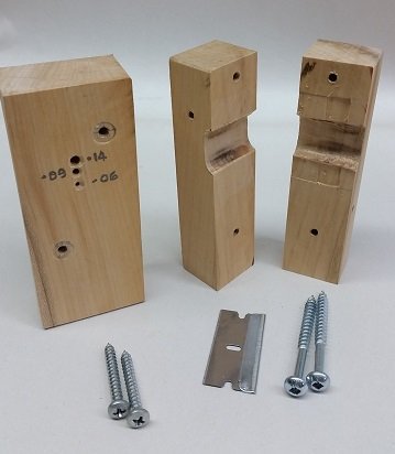
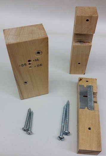
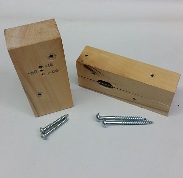
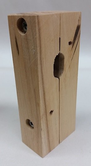
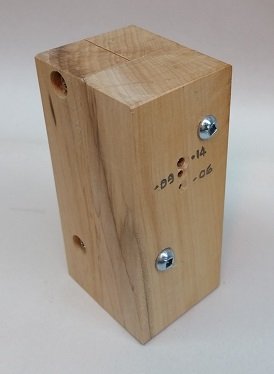
I spent a few hours this afternoon making a bamboo skewer slicer. There are eight parts: 1 - The front block with three holes at 0.14", 0.09" and 0.06" diameter, there is a bevelled lead in to help guide the skewer. (Skewers seem to be 0.125" max diameter) 2 and 3 - the screws to fasten it to the back blocks 4 and 5 - the back block halves of which one has a pocket for the razor cutter 6 - the razor cutter blade 7 and 8 - the screws to fasten the back halves together. Photos below will explain the assembly. It splits the skewers like a charm.... just needs a tiny adjustment on the upper hole to centre the cutting blade better. But that is for another day... MERRY CHRISTMAS everyone.

-
or more so when I am entered into the equation.
-
Of course you are right Druxey, but I cannot split them straight! They wander to one side. Must be my wonky eye! I read that the round outsides of the skewer needs to be cut off to leave a square to draw through the plate. Taper the lead end to feed. So I thought two razors each mounted at 5° cutting relief angle opposite to each other would allow one pass followed by one quarter rotation to pass again giving me a square and eliminating the rounded outside bits. This seems like a lot of waste. I played with modelling and it is do-able... on paper. If I made a block with a small guide lead in hole sized for the bamboo skewer diameter, with a single razor blade on centre about 1" in the tunnel, and a larger discharge hole for the split pieces to come out I might have better success. I can then put the two halves back together and turn it 90° to pass it through again and quarter it. Theoretically this will leave me with four pieces that I can get 0.04" (1mm) diameter pieces from. At 1:64 this is 2-1/2" (63.5mm). If this works I could possibly have a smaller lead hole below the first to pass the quarter piece through to split it in two allowing a 0.028" (0.7mm) diameter piece. At 1:64 this is 1-3/4" (44mm). If this works, making straight quick cuts, it would reduce my scrap and the number of draws to get it down to size. I'll see if I can put something together this week.
-
Yes they were in the boxes but were not really any help as I didn't really appreciate the importance of some nor of information contained in other articles until I looked at them and so may not have seen three quarters of what I should have. You have to remember I am a babe in the woods... or seaweed. I flipped and looked at each page and read quite a few great articles and tips. Funny how I kept seeing the same author names repeated over and over again. Presently looking at how to make a block to hold two razor blades to slice my bamboo skewer rounded edges off to get a nice straight small square length to pass through the draw plate to make some treenails. The skewer is about 0.121 inch (3mm) diameter and the largest hole in the drawplate is #59 (0.059 inch = 1.5mm diameter).
-
A chatter groove was added to the trailing vertical end of the rudder to eliminate chatter felt back through to the steering mechanism due to flow turbulence in the water at the sharp change or loss of shape of the rudder. I have seen some models with the chatter groove in the rudder. I have seen models with plating wrapping around the rudder (over any chatter groove). Did the copper plating conform to the profiled recess of the chatter groove, or was it no longer necessary because of the copper plating?


-
My eyes are exhausted. My brain is sore. My fingers are numb. I was fortunate to acquire 108 back issues (2000-2017) of Ships in Scale and 145 back issues (1951-1997) of Nautical Research Guild magazines at our last club meeting. I already had the 2014 to present issues of NRG but went through those again as I couldn't recall what articles were in them that I might need down the road. I've just moments ago completed reviewing them all, scanned the articles that captured my interest, or that I thought were going to be handy with my build later on. I created Excel indexes for these ( plus the 1935-1939 issues of Marine Modeller and 1972-2008 issues of Model Shipwright) so they can be searched and recalled quickly. I am certain I will wake up tomorrow and not remember a thing I just learned. This magazines will now be gifted to another in our club.
-
sorry that didn't work I tried again check your PM
-
Just sent you a private message. Hope it helps.
-
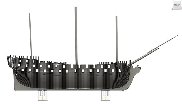
Recovering from my last (reoccurring) eye injection on Tuesday Morning so I cannot go into my shop as I must avoid dusty environments... So it will wait a couple more days. I went to our local club meeting on Sunday and took my model and 6-32 threaded rod and hex nuts with the specific intention of discussing the mounting pedestal locations as I was concerned the holes and captive pockets for the hex nuts would go right into a scarph joint through the keel. Luckily both of the guys I hoped to talk too were there. It was suggested that since I had a drawing/3D model, I might add the lower masts, bowsprit and jib boom, then add the mounting pedestal/bolts and move them about until it looks proper. I was also told not to worry so much about going through a scarph joint as everything else on her will make her structurally sound in the end. I still want to avoid the scarph joints.... so I modelled it up and here it is. Another fellow suggested I visit a model shop and get some 6-32 blind nuts to insert into the keel rather than cut out pockets for a modified hex nut. So I may be doing this next week... or possibly looking at steel rivet nuts.
-
Derek, the answer is yes. I've used the WPL main branch 3D printer for my 1:12 scale 9 pdr gun barrel which is another build log on the forum here. The charge $0.00 (free) to print but inticate parts might be a disappointment. One of the fellows in our local club has a 3D printer that will do it. He printed all my gun barrels for this build (3 different sizes) at 1:64 scale.
-
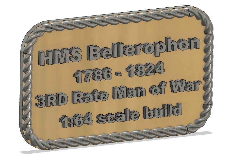
Thank you Mark but you give me far more credit for my actual skill level than I deserve. Practically every other designer I've had the pleasure to be associated with had thousands more practical hours at it then I, and were far more proficient... this is what comes from moving into lower level management! Well, after more time than I care to admit, I completed a 3D nameplate in Fusion 360 that I will attempt to print in PLA-wood filament. Hope it looks half decent for a first attempt when done. Although there is a learning curve I believe the free Fusion 360 program will work fine for me and fill my needs. With some more practise over time I should become as quick as I am attempting to type this out with all my fingers as learnt early in High School many MANY years ago, as opposed to the mere two fingers that got me through the final years of employment after computers entered the work force.
-
Spent a few more hours today doodling with the free Fusion 360 hobbyist version and the test drive of Inventor LT. Discovered fusion refers to mates as joints and I can easily create a fusion 360 assembly from stp files of my inventor parts. I may become a convert yet.
-
Why thank you Derek. When I started I estimated this would take about 10 years. 🤔 You may start the clock now. 😉
-
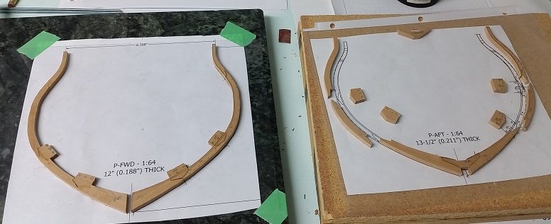
I have installed P-forward and P-aft. Now I start putting spacer chocks in.

-
I am still assessing the two programs (Fusion 360 versus Inventor LT 2020). With out the assembly of parts option I will have to build my assembly in a part file which will be a change in thinking. Like stepping back to the days of pencil and paper.
-
So the answer to my latest problem is that the user must join Fusion Team, create your own "team" of one, and away you go. This seems to be what they are migrating towards. If so why don't they just delete the personal hub option from the new program downloads? Fusion Team was created to answer the problem of businesses having employees with company models on the employees personal data log in the cloud. If the employee leaves the company they still have the models. Plus it was difficult to manage who gets access to projects or files in projects. With the Team creation the business company administrator controls it all and it all remains with the business. That makes sense to me.
-
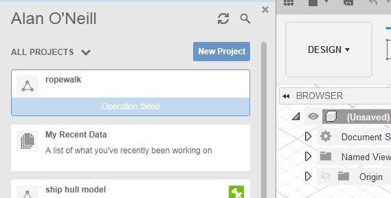
Jeez, sorry for not answering that question Derek... I didn't get an e-mail notification of your posting. So I am still tooling about with Fusion 360 and Inventor LT (2020 version) with about 20 days left in the free trial for the Inventor. I had successfully create a Project to put my 3D hull models and rebuilt my assembly. On Saturday Fusion would not let me make a new Project to insert my ropewalk design models. Try as I might it will not cooperate. I checked on the board and there seems to be a glitch they don't explain but they need to perform some tweek at their end. So I posted my problem in the support group, requested help and an explanation. Sunday, no success... and no one in support viewed my request. Monday, no success... and 10:54 am... no one viewed my request. hmmm.
-
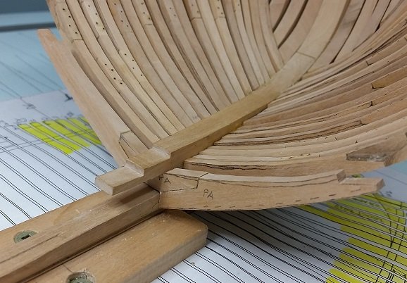
All forward cant frames are installed. I have P-forward and P-aft (both square frames) to install before I move to the next stage. P-fwd is cut and glued. P-aft is cut and the foot is assembled tested, adjusted and finally dry fit. Now I can complete gluing it together. Hope to be installing frame spacer chocks by Thursday so I can bring it back to our club meeting this Sunday.

-
Should have also mentioned I purchased #6-32 threaded rod, hex nuts and flat washers a Lowes in Niagara Falls on Tuesday. This will be to mount the model to the build board through the keel, but I will do this after sanding the cant frames which at my pace may be next year. Right Derek? Have to repair my uncles coffee table first.
-
Now I just discovered STEP files are better than IGES files because they are newer, IGES is 20 years old and can convert with gaps or missing info. still trying them both out. Inventor LT (at $520 Canadian a year) is closer to what I am use to using and all my files are on my computer. Fusion 360 for hobbyist is free, very similar, but cloud based... your stuff goes off site like all those celebrity photos that never should have seen the light of day. I've read you can save to your hard drive and work on it. I'll have to give this a try. I am not a fan of having no choice but to have my files being "out there". Is that privilege worth $520 a year?
