AON
-
Posts
2,871 -
Joined
-
Last visited
Content Type
Profiles
Forums
Gallery
Events
Everything posted by AON
-
Assuming you're not referring to the leeches. Yikes! I'll bet they would have preferred medicine and care from the late 20th century or now (21st century.
-
Ach, it's nothing but a flesh wound. Throw some leeches on it and walk it off.
-
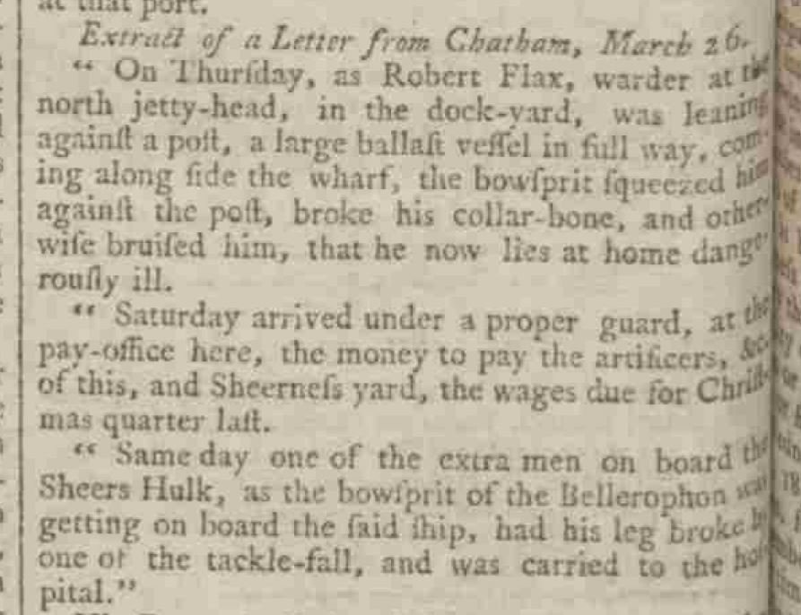
Being anywhere near ships not a sea was dangerous. (1787) Broken collar bone Broken leg
-
I suppose beer kept better over time than fresh water. Although called fresh, beer was cleaner. Beer kept the sailors in a much better mood than water ever could.
-
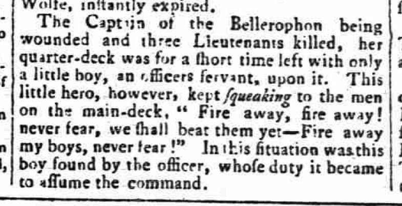
It is in the thick of the fight, the Battle of the Nile (1798), guns booming, smoke and fire all around you, wood exploding and splinters fill the air. All the Officers around you on the quarterdeck are killed, the Captains wounded and taken below. What do you do..... Assume command until an adult shows up of course!
-
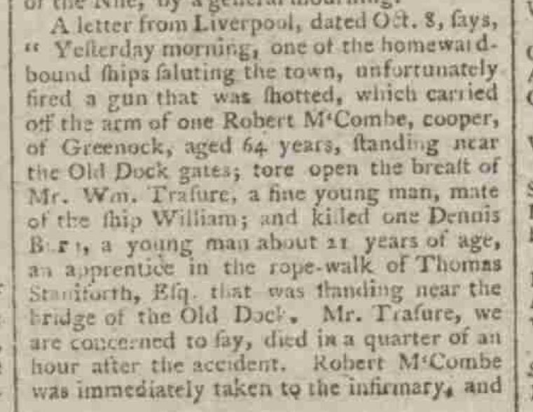
Ship returning home fires a salute to the town and takes off one mans arm, opens another's chest, and kills one other. I wonder what happened to that Captain? 1798

-
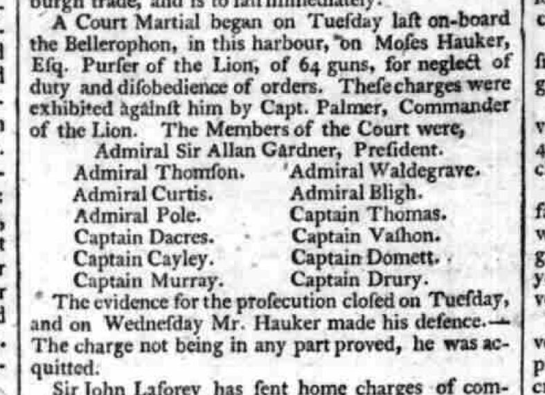
Speaking of Captain Bligh.... I wonder what ever happened to him after the mutiny and he was cast afloat by the crew? Well he became an Admiral of course!
-
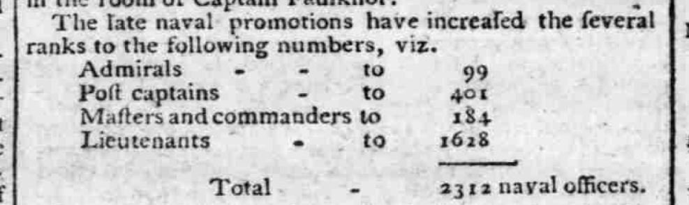
Possibly a little top heavy in upper management??? 1794
-
 Bad and good news for me. The Bolt and Nut supplier in St. Catharines failed to fill my order for the #6-32 stainless steel helicoil inserts. Amazon.com has the item and advertises they will ship it to Canada but try to place the order... sorry! Amazon.ca does not offer it. I have since found Ackland-Grainger has the item and at half the price. Placed the order on line yesterday. Now we wait to see if they follow through. Going to visit the local wood carving club this afternoon.
 -
I believe 414 ships listed. I cannot imagine the sight of that many sails. Good time to have shares in wood, cloth, rope and gun barrel businesses.
-
(Not sure if this warrants a warning but... ) Which reminds me of a joke: Did you know that the Navy invented sex.... it was the Army that introduced it to women.
-
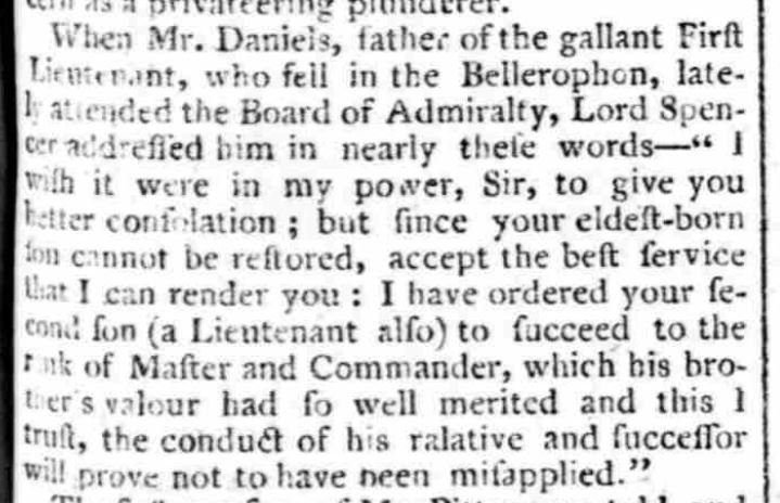
and this poor bugger had to live in the shadow of his brothers sacrifice. (1798)
-
I am waiting with baited breath for this hillarious topic to come full circle.... with corners.
-
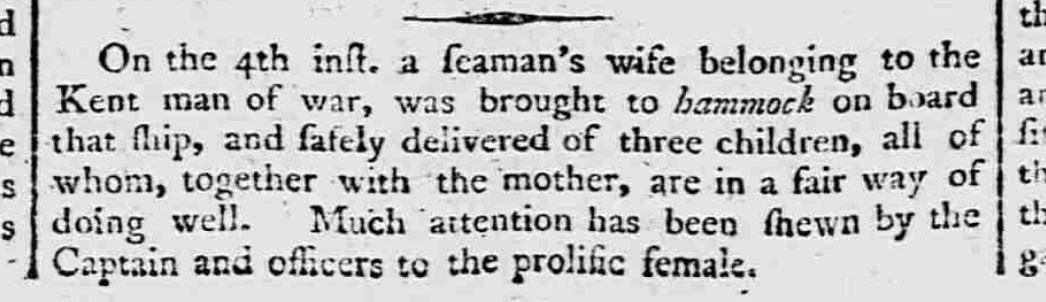
here is one you wouldn't think of.... dated 1799
-
Also found an article from 1790 listing every ship in the British Navy, where it is, and who was the commander. I suppose this made the spy's job easier.

-
I stumbled on the following letter printed in 1799 that I thought was quite interesting. It relates to the nicknames of ships...

-
Had a most enjoyable afternoon. Started fairing the hull. Just wanted to be the first person in history to ever write those words. Also, my #6-32 helicoil inserts came in today. One problem, they were not stainless steel. The supplier in Cambridge is overnighting them by courier to St. Catharines. I should pick them up Monday afternoon.
-
And Lloyd's went by tonnage to size everything per Wooden Ship Building, Charles Desmond, 1919
-
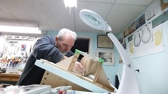
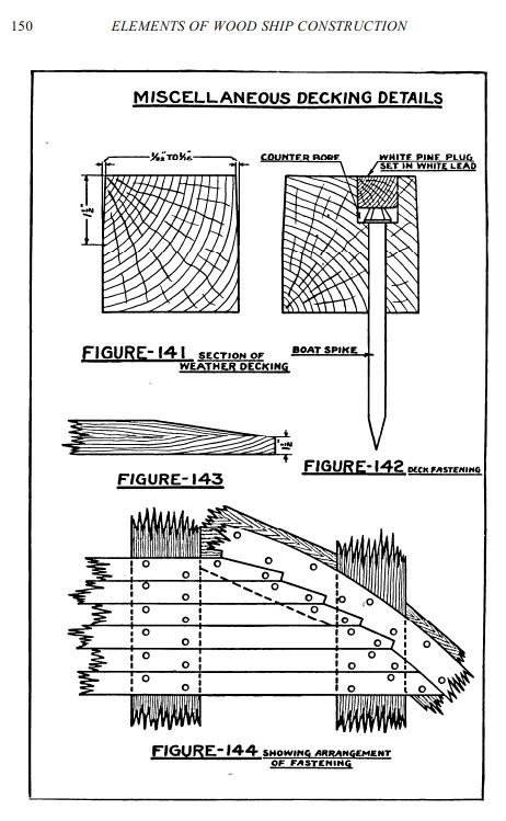
Here is a video showing the method of making treenails that was shown to me by a very talented model maker that is in our local club. making treenails -1.wmv Of course, for all that have done it over and over before, it is quite a simple process... but for the rest of us, a picture is worth a thousand words and a video is priceless. I always tend to make more out of things then they are. Other things I'd learned. Treenails and bolts are used in the planks on the sides of the hull. The deck planks were spiked and plugged and the plugs were barely (if at all) noticeable. The thickness of the hull planking determined the diameter of the bolt or treenail which were not the same size. Bolting/treenailing patterns differed outside versus inside. Wedges were driven into the ends of treenails to make them hold better. Deck planking did not always run straight on the upper (weather) decks, in the earlier periods, up to somewhere in the mid 1700's, they bent inwards at the bow and stern. The head of a deck spike was about 5/8" diameter. Thickness of hull planking / Diameter of Bolts / Diameter of Treenails (Wooden Ship Building, Charles Desmond, 1919 - same as ASA dated 1885) 1" / 1/2" / 7/8" 2-1/2" / 5/8" / 1" 3" to 3-1/2" / 3/4" / 1-1/8" 4" to 4-1/2" / 7/8" / 1-1/4" 5" to 5-1/2" / 15/16" / 1-3/8" 6" and over / 1" / 1-1/2"
-
Thank you Mark. Still needs some metal work but I will get to that at a later date.
-
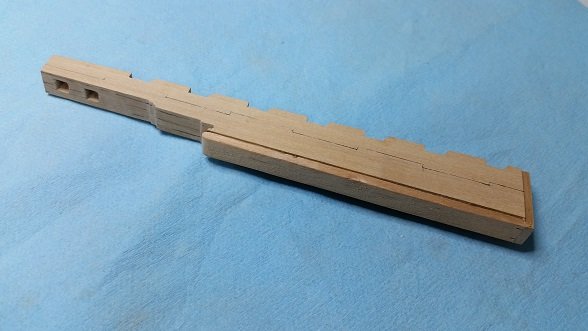
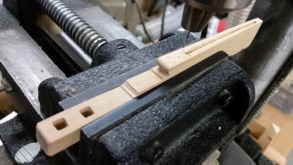
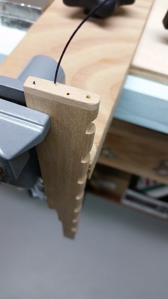
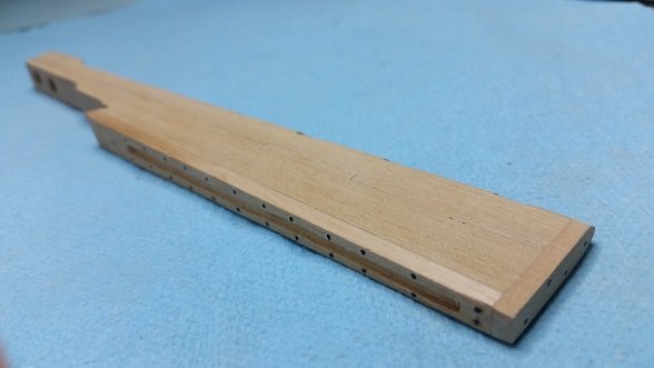
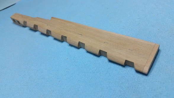
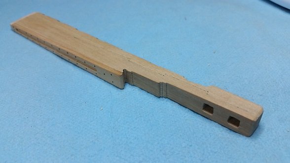
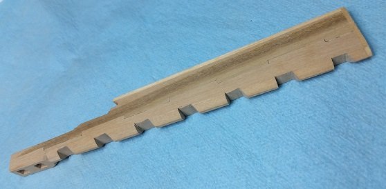
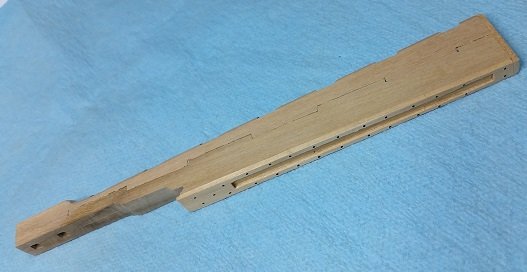
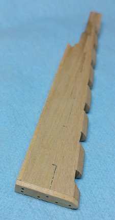
RUDDER: So here are some photos of my last and final rudder. Major differences are: 1) the chatter groove is cleaner 2) the tiller holes are tapered at 12" square opening inboard; smaller square hole outboard measuring 1/3rd the width of the rudder head. 3) the table joint was made in two different shades of Castello to try to make the joint more visible After comments at our local club meeting yesterday I will be softening the rudder corners/edges some more with a fine grade sand paper, and squaring the tiller holes a bit cleaner with a micro chisel. Files can only do so much to a make a round hole square... and I am certain talent plays a bigger part than the file. TREENAILS: Regarding my tutorial in making treenails last week... I was shown to hold the skewer perpendicular to the floor, flat end up, tightly against the edge of a work table with your thumb clamping it there (thumb safely below the top surface of the table so as not to cut your self). There should be about an inch ( 25 mm) or more protruding above the table edge. Using a sharp knife place the cutting edge on top of the end of the skewer, across the centre as best as you can and push down slightly increasing pressure so the blade slices through to the table top in a controlled cut. Do not do this at your good dining room table unless you are a bachelor and want to remain so. Once scored remove the skewer from the table and turn it 90° so it is horizontal to the floor and place the knife blade back in the scored/cut end. Grab the parted end with your free hand and pull it through the knife. You now have two clean straight cut halves (I haven't tried this yet but I saw it done multiple times). Now repeat with one half, and again with one quarter until you have a length at a size that will feed into the largest hole in your draw plate. You might have to sharpen one end of the piece to aid feeding it into the tiny hole. Grab it with your parallel pliers and pull it through a couple times, then jump a hole and go down to a smaller hole and repeat the process until you reach the size/diameter treenail you need. The draw plate has tapered holes so the smaller diameter on one side is the cutting edge. On mine, the hole sizes are stamped on the large hole side, the out feed side. You feed into the small hole side. I was told that if the wood sliver piece is ever so slightly too large to feed into the small hole you can try pushing it in the out feed side to crush the fibres down to allow it to feed into the infeed side... or resharpen it to a point with a knife. I have ordered the parallel pliers Druxey recommended in an earlier post (#999 above) as they are indeed instrumental in causing less damage to the tiny bamboo. They have not come in yet. I may make a video when the darn pliers show up. It is a simple enough process once you've see it and have done it.
-
Mark I attended our local club meeting yesterday afternoon and once again I left having learnt a number of things I otherwise would never have read in a book. Two of the fellows there are "professional ship modellers" and they seal everything with a water based sanding sealer to fill the pours and protect the wood. They then sand the work after dried with incrementally fine sandpaper to get the smooth quality desired for a bare or painted surface. I suspect your tape will stick to this. This is from the makers website: EM1000 Universal Sanding Sealer is designed to penetrate deeply into the cell structure of the substrate being sealed, promoting enhanced adhesion qualities. The exceptional clarity of this small particle size resin enhances wood grain color image and magnification. EM1000 dried quickly and is easy to sand. EM1000 can be used underneath all of our interior-grade clear finished. .... and you can get it at Lee Valley Tools! (Road trip)
-
Thank you Mike and Derek (and everyone else), but if you saw it up close in real life... I just completed my 3rd and last version of the rudder, and will take it to our club meeting this afternoon. I chose two slightly contrasting colours of costello to try to bring out the tabling a bit more clearly. Also, I visited a club member last week and had a tutorial on making treenails. His hands on method made minced meat of my block. But then again he has been at it for ages. I will be posting more later.
-
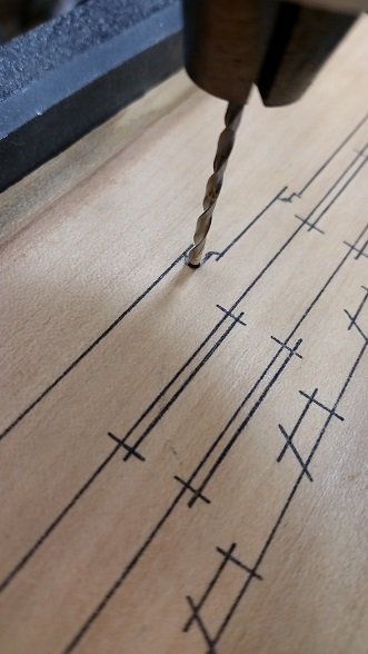
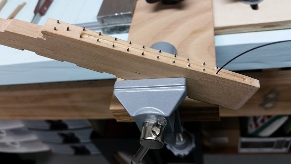
It seems my supplier may not have put my order in for my #6-32 stainless steel helicoil thread inserts as they are not in and they have no record of the order being placed just before the holiday shut down. So possibly they might be in by early next week? I took another shot at making the rudder and although it looks much better, I believe the third time will be the charm (practise makes perfect). I decided to drill a hole to create the relief radius in the upper rear ornate shaping. I should have possibly chosen a smaller diameter drill. I was quite impressed with my first attempt at tabling (stepped cut and fitting of the two main pieces) and my second attempt was that much better. The backing and sole plates were glued on prior to sanding down the tapered width this time. This seemed to work better. I cut the chatter groove in the backing plate without any real direction or description. Where does it start and stop? What is the width and depth? With what I know about fluid dynamics, and realising the plates are 6 inches thick, I assumed 3 inch depth and 1/3rd the width would seem realistic. I did not get it cut as straight and clean as I had hoped to, but the practise and process is tried. I will practise on a piece of scrap to get a clean crisp cut for next time. The two square holes at the head for the main and spare tillers were drilled out and the corners were filed to shape. I decided to use one size though the piece where as in reality it was 12 inches square forward and tapered smaller to a square hole 1/3rd the width and height of the width of the rudder at that location. My next and final attempt will be properly sized even though no one will likely see it. While shaping the taper at the pintle cutout side corners I slipped and took a little extra off in one spot that no one will likely see ... but I know it is there and it bugs me. So I will do it once again. I've got the process figured out and the practise in.