Ferrus Manus Posted July 30 Author Share #61 Posted July 30 10 hours ago, Louie da fly said: Ah, but the écusson de flèche and the écussons du bandinet turned out well Even after reading the thread, all I can assume is that you mean "ornamental decorations at the extreme aft"... Quote Link to comment Share on other sites More sharing options...
Ferrus Manus Posted July 30 Author Share #62 Posted July 30 These are the golden Tritons and angels, ready to go on the ship: GrandpaPhil and Hubac's Historian 2 Quote Link to comment Share on other sites More sharing options...
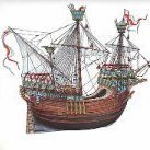
Ferrus Manus Posted July 31 Author Share #63 Posted July 31 And on the ship: Hubac's Historian, Baker and GrandpaPhil 3 Quote Link to comment Share on other sites More sharing options...
Baker Posted July 31 Share #64 Posted July 31 Nice paint job. All that gold, i need my 😎 😉 Ferrus Manus, Knocklouder and Hubac's Historian 2 1 Quote Regards, Patrick Finished : Soleil Royal Heller 1/100 Wasa Billing Boats Bounty Revell 1/110 plastic (semi scratch) Pelican / Golden Hind 1/45 scratch Current build : Mary Rose 1/50 scratch Gallery : Revell Bounty Pelican/Golden hind 1/45 scratch Shore leave, non ship models build logs : ADGZ M35 funkwagen 1/72 Einhets Pkw. Kfz.2 and 4 1/72 Autoblinda AB40 1/72 122mm A-19 & 152mm ML-20 & 12.8cm Pak.44 {K8 1/2} 1/72 10.5cm Howitzer 16 on Mark. VI(e) Centurion Mk.1 conversion M29 Weasel 1/72 SAM6 1/72 T26 Finland T26 TN 1/72 Autoprotetto S37 1/72 Opel Blitz buses 1/72 Boxer and MAN trucks 1/72 Hetzer38(t) Starr 1/72 Cleaning the 1/72 military collection Si vis pacem, para bellum Link to comment Share on other sites More sharing options...
Ferrus Manus Posted July 31 Author Share #65 Posted July 31 Louis is the Sun King, so sunglasses might be appropriate. I guess it seems obvious that his ships would reflect his title. Baker 1 Quote Link to comment Share on other sites More sharing options...
Ferrus Manus Posted July 31 Author Share #66 Posted July 31 The stern lantern and flagpole: And the ship's guns, surrounded by the forecastle deck timbers: GrandpaPhil, Ian_Grant and Hubac's Historian 3 Quote Link to comment Share on other sites More sharing options...
Louie da fly Posted July 31 Share #67 Posted July 31 11 hours ago, Ferrus Manus said: Even after reading the thread, all I can assume is that you mean "ornamental decorations at the extreme aft"... Mainly just messing with you - If you look at the photo in your post #63, the écusson de flèche is the decorative medallion on the end of a red beam at the very top. The écussons du bandinet (actually it should be écussons des bandinets, to make it all agree as a plural) are the two decorative medallions at the ends of red beams just above each side of the big decorative thingy on the stern with the globe of the world on it. "Écusson" means something like "shield thing" - perhaps escutcheon would be a good translation. The usual meaning of flèche is "arrow", but by extension it would presumably be anything long and thin and arrow-like - such as the red beam at the top. Bandinet is perhaps "little band", presumably meaning the beams either side, supporting the escutcheons. Steven Ferrus Manus and Hubac's Historian 1 1 Quote It's not really a ship model unless you've bled on it. CURRENT BUILDS Venetian merchant Ship from Basilica of San Marco Golden City - Ballarat paddlewheeler FINISHED Australian couta boat RMS Titanic HMVS Cerberus 11th century Byzantine dromon Winchelsea Nef - Late 13th century Mediaeval ship Henry Grace a Dieu - Rebuild of 1:200 model I started in 1967 https://modelshipworld.com/topic/36379-mistydeefer-by-louie-da-fly-finished-restoration-decor-yacht/#comment-1040663 Mistydeefer - restoration of decor model yacht Link to comment Share on other sites More sharing options...
Ferrus Manus Posted July 31 Author Share #68 Posted July 31 The apostis assemblies went on far easier than I expected they would, given the imperfect alignment of the supports. The next job is to glue on the rest of the anchor equipment, followed by more decorative stuff at the stern. The ladders will be saved for the very end, as I don't trust them not to break off. GrandpaPhil and Hubac's Historian 2 Quote Link to comment Share on other sites More sharing options...
Ferrus Manus Posted July 31 Author Share #69 Posted July 31 Interestingly, there is a thole pin where the cooking pan is. Would there simply have been an oar/seat assembly that could be removed for cooking? Quote Link to comment Share on other sites More sharing options...
Ferrus Manus Posted August 1 Author Share #70 Posted August 1 With the exception of the flagpole, the forward area of the stern is done. GrandpaPhil, Knocklouder, Ian_Grant and 1 other 4 Quote Link to comment Share on other sites More sharing options...
Ferrus Manus Posted August 1 Author Share #71 Posted August 1 The 61 footrests, painted, stained, and installed on the ship: Baker, Ian_Grant, Hubac's Historian and 1 other 4 Quote Link to comment Share on other sites More sharing options...
Louie da fly Posted August 1 Share #72 Posted August 1 7 hours ago, Ferrus Manus said: Would there simply have been an oar/seat assembly that could be removed for cooking? Quite possibly. I was somewhat surprised to find that not all the oarbenches on a galley necessarily got used all the time. Sometimes only half the oarsmen were rowing while the other half had a rest - and I'm sure other configurations existed as well. After all, cooking only happened at certain times of day, and perhaps that pair of oars (one each side, for balance) were "retired" while that was happening. Steven Hubac's Historian and Ferrus Manus 1 1 Quote It's not really a ship model unless you've bled on it. CURRENT BUILDS Venetian merchant Ship from Basilica of San Marco Golden City - Ballarat paddlewheeler FINISHED Australian couta boat RMS Titanic HMVS Cerberus 11th century Byzantine dromon Winchelsea Nef - Late 13th century Mediaeval ship Henry Grace a Dieu - Rebuild of 1:200 model I started in 1967 https://modelshipworld.com/topic/36379-mistydeefer-by-louie-da-fly-finished-restoration-decor-yacht/#comment-1040663 Mistydeefer - restoration of decor model yacht Link to comment Share on other sites More sharing options...
Ferrus Manus Posted August 1 Author Share #73 Posted August 1 Sometime, I want to do a model of a Medieval galley. Quote Link to comment Share on other sites More sharing options...
Louie da fly Posted August 1 Share #74 Posted August 1 Great idea. There are some great contemporary illustrations to base one on. 1173-1196 Galley - Annals of Genoa f. 70r. Double-banked galley. 12th century: Museu Nacional d'Art de Cataluna from Cantigas de Santa Maria - late 12th century Spanish. Note - in accordance with the text, the first galley's mast is broken. from Peter of Eboli's Liber ad Honorem Augusti, Italian 1194-96 Steven Hubac's Historian, Ferrus Manus and GrandpaPhil 2 1 Quote It's not really a ship model unless you've bled on it. CURRENT BUILDS Venetian merchant Ship from Basilica of San Marco Golden City - Ballarat paddlewheeler FINISHED Australian couta boat RMS Titanic HMVS Cerberus 11th century Byzantine dromon Winchelsea Nef - Late 13th century Mediaeval ship Henry Grace a Dieu - Rebuild of 1:200 model I started in 1967 https://modelshipworld.com/topic/36379-mistydeefer-by-louie-da-fly-finished-restoration-decor-yacht/#comment-1040663 Mistydeefer - restoration of decor model yacht Link to comment Share on other sites More sharing options...
Ian_Grant Posted August 1 Share #75 Posted August 1 Ferrus, your nice build is proceeding at a very brisk pace. Are you getting any sleep? 😉 Ferrus Manus 1 Quote Link to comment Share on other sites More sharing options...
Ferrus Manus Posted August 1 Author Share #76 Posted August 1 2 hours ago, Ian_Grant said: Ferrus, your nice build is proceeding at a very brisk pace. Are you getting any sleep? 😉 Not really. Ian_Grant 1 Quote Link to comment Share on other sites More sharing options...
Ferrus Manus Posted August 1 Author Share #77 Posted August 1 (edited) So, today I started on the work I'll have to do before I close up the forecastle. The first order of business was the gun rigging. Originally, I wasn't going to rig the guns, but since they gave me two out of the three sheaves I needed (and then didn't mention gun rigging in the instructions) I figured I might as well. I bashed together another sheave for the 36 pdr, then got to work. The interesting bit was the rigging of the 36 pdr. I drilled two holes for the ropes in the front of the gun carriage, inserted eyebolts, tied on the ropes, and did the exact same thing I did for the 24 pdrs. The interesting thing about it was the fact that the ropes run to the catwalk, which means they actually travel upward from their sheaves. Edited August 1 by Ferrus Manus GrandpaPhil, Hubac's Historian, Knocklouder and 1 other 4 Quote Link to comment Share on other sites More sharing options...
Ferrus Manus Posted August 1 Author Share #78 Posted August 1 (edited) 10 hours ago, Louie da fly said: Great idea. My favorite galley story is that of the two Italian brothers who attempted to find a sea route to India in the 13th century (I think?) using two galleys. They rounded the coast of Morocco and were never seen again, alive or dead. Edited August 1 by Ferrus Manus Ian_Grant 1 Quote Link to comment Share on other sites More sharing options...
Ferrus Manus Posted August 1 Author Share #79 Posted August 1 The next thing I need to do before closing up the forecastle is the anchors. When I dry-fitted the anchors together, I was taken aback by how humongous they are. If they were made of cast iron, surely they would have weighed in considerable excess of a ton apiece. Now, this begs the question: how were they weighed? I see no form of winding gear on board the ship. Not a capstan, not a windlass, nothing. Granted, if a hundred men lined up on the catwalk and pulled, each of them would probably only have to lift 40 pounds max, including the weight of the anchor cable. I want to display the anchors fully hauled in and stowed. This begs a different question: where do you put 60+ feet of anchor line? There isn't much room for it on the forecastle, although that's what Heller says to do. This is how Heller commands one to stow anchor: After seeing the discussion on Michael D's build, my assumption that this was completely wrong was confirmed. In fact, this is so incorrect that the davits on the beakhead would snap under the weight of the anchor if they attempted this. the davits, according to an expert who informed his build, were actually used to weigh the anchors' buoys. The Landstrom book depicts the anchor stowage almost as incorrectly. The only major difference is that Landstrom belays the catting line on the huge timber heads on the forward bulkhead instead of a cleat on the davit, and runs the anchor cable off to some unknown location. This implies the existence of a rope locker on the real ship, but I am unaware as to where it would be located. Back to the anchor buoys- they are included in the kit and mentioned in the very beginning where you are instructed to set them up, but never again. I plan to show them hanging off the bulkheads just outboard of the anchor itself, with the line in a simple coil underneath the anchor, not attached to it in any way. I don't plan on setting up the anchors until I have a clear idea of how the anchor was weighed and where the anchor line goes. GrandpaPhil 1 Quote Link to comment Share on other sites More sharing options...
kirill4 Posted August 1 Share #80 Posted August 1 Good day, Dear Ferrus Manus, Check this , what expert says... Ferrus Manus 1 Quote Current Build: Spanish Galleon, Lee, 1:100 https://modelshipworld.com/index.php?/topic/6262-spanish-galleon-1607-by-kirill4-lee-plastic-1100/& https://karopka.ru/forum/forum190/topic10341/ Dutch 16-17 Arts Sailing Vessels in details https://www.rijksmuseum.nl/en/rijksstudio/1845326--kirill-shabanov/collections/arts Link to comment Share on other sites More sharing options...
Ferrus Manus Posted August 1 Author Share #81 Posted August 1 While the video shows how to weigh anchor on a galley, it does not show how the anchor cable is stowed. My only guess is that it must be removed and sent to some sort of rope locker, then retrieved when it's time to drop anchor. The video has been very helpful, though. Hubac's Historian 1 Quote Link to comment Share on other sites More sharing options...
Ferrus Manus Posted August 2 Author Share #82 Posted August 2 The forecastle area is complete with the exception of the finalization of the 36 pdr's rigging. GrandpaPhil, Ian_Grant and Hubac's Historian 3 Quote Link to comment Share on other sites More sharing options...
Ferrus Manus Posted August 2 Author Share #83 Posted August 2 I know that the beginning of the rigging is still pretty far out, but I still have to clear something up. Heller swears these things are belaying pins. I've even seen some Corel builders use them as such. However, having rigged plenty of fore-and-aft vessels, this makes absolutely no sense whatsoever. My idea is that these are the ladder rungs to get up into the forecastle. If they were used as pins, there would be no way up. I haven't seen another form of ladder on any version of this ship. For that reason, I will be belaying pretty much all the rope work to cleats or something similar. I even have a relatively solid idea of where all the cleats are to go. GrandpaPhil, Ian_Grant, Baker and 1 other 4 Quote Link to comment Share on other sites More sharing options...
Ferrus Manus Posted August 2 Author Share #84 Posted August 2 The forecastle decks are painted and glued into place: The two painted lower forecastle bulwark assemblies: GrandpaPhil, 72Nova, Hubac's Historian and 2 others 5 Quote Link to comment Share on other sites More sharing options...
72Nova Posted August 2 Share #85 Posted August 2 Moving along quickly, maybe too quick Michael, with your skill set improving I'd like to see you spend a few extra minutes detailing each part, like scraping away the casting ridges, filling sink holes and finishing up with a light pass of some fine sandpaper, you'd be surprised the difference it makes! Shes looking great so far👍 Michael D. Ferrus Manus and Hubac's Historian 1 1 Quote Completed: https://modelshipworld.com/topic/20561-reale-de-france-by-72nova-finished-heller/ HMS Victory 1765: https://photos.google.com/share/AF1QipPrp-3y7ntwH1vwfFsMMf0bWByRebwVKqePmRLqCx3aptq5sMlGZp_LtYv0v-seiQ?key=RWdjbWRKQWs2X1JSaDAyVTRuMHk5U3dOTHJCSDVB Completed: https://modelshipworld.com/topic/33007-vasa-by-72nova-airfix-plastic/ Link to comment Share on other sites More sharing options...
Ferrus Manus Posted August 2 Author Share #86 Posted August 2 These are the painted forecastle walls: These grand totaled about two hours... ...and still more to come. As per Michael D's advice, I will have to go over the top of them with a knife. I got them to the point where the gold mistakes can't be seen with the naked eye, but there's still more to do on the back. There are several injection mold marks that I want gone, and I might even scribe in some wood detail. I remember finishing up the Esmeralda at about this time last year. That took me 6 months. I think that my skills have improved since then in the wrong way. I have attempted to be faster instead of better, and I think it's just a matter of retraining my mind to stop rushing. Time to take a break for a few hours. GrandpaPhil and Hubac's Historian 2 Quote Link to comment Share on other sites More sharing options...
Ferrus Manus Posted August 3 Author Share #87 Posted August 3 Alrighty. The offending seam lines were mostly visible on the top of the forecastle walls, so I scraped them off with a knife: Then, I scraped the paint off the inside of the walls, and rescribed them with wood grain: I proceeded to fill in the injector pin marks with Tamiya plastic putty: One of the repainted walls: Afterwards, I cleaned up the paint on the front and shaded the gold: The decorative scenes on the forecastle show Greek/Roman square-rigged galleys and galley battles. GrandpaPhil and Hubac's Historian 2 Quote Link to comment Share on other sites More sharing options...
Ferrus Manus Posted August 3 Author Share #88 Posted August 3 The forecastle walls are positioned on the deck in their final arrangement, in which they will be glued. Ian_Grant, GrandpaPhil and Hubac's Historian 3 Quote Link to comment Share on other sites More sharing options...
Ferrus Manus Posted August 3 Author Share #89 Posted August 3 I glued the forecastle pieces in and finished the 36 pdr's rigging today. Then, I dry-fitted the port side catwalk/footboard assembly: Painting the piece was not that hard, but installing it was a different story. I put glue on the pins on which the footboards rest, as well as the outer part of the supports for the catwalk. Then, I fought the piece into place. I proceeded to think quickly, putting my metal ruler over top of the footboards and resting my "everything-cup" on top of that, ensuring they sat level on the ledge upon which they sit. The starboard side was not much easier. Both pieces had a slight horizontal warp, but the starboard side was worse than the port. I have yet to glue the aft footboards on the port side assembly, or any on the starboard. I have yet to fix the missing footboards, but I have a plan. I discovered shortly after starting the model that I had been erroneously given two copies of sprue #7 in the kit. Sprue #7 contains the main mast, the center catwalk pieces (which will come in handy when we eventually put in the section surrounding the main sheaves) and most crucially, the two fore-and-aft sections of the awning support. These pieces are almost the exact same diameter as the footboards, and the fact that I have extras means I can hack two of them up into four new footboards to replace the missing sections. Hubac's Historian, Ian_Grant, Baker and 2 others 5 Quote Link to comment Share on other sites More sharing options...
Ferrus Manus Posted August 3 Author Share #90 Posted August 3 Fun fact: My "everything-cup" is actually older than me, and features the names, portraits and terms of all U.S. presidents up to Clinton. Baker 1 Quote Link to comment Share on other sites More sharing options...

Recommended Posts
Join the conversation
You can post now and register later. If you have an account, sign in now to post with your account.