HOLIDAY DONATION DRIVE - SUPPORT MSW - DO YOUR PART TO KEEP THIS GREAT FORUM GOING! (Only 53 donations so far out of 49,000 members - C'mon guys!)
×


paulb
-
Posts
117 -
Joined
-
Last visited
Content Type
Profiles
Forums
Gallery
Events
Everything posted by paulb
-
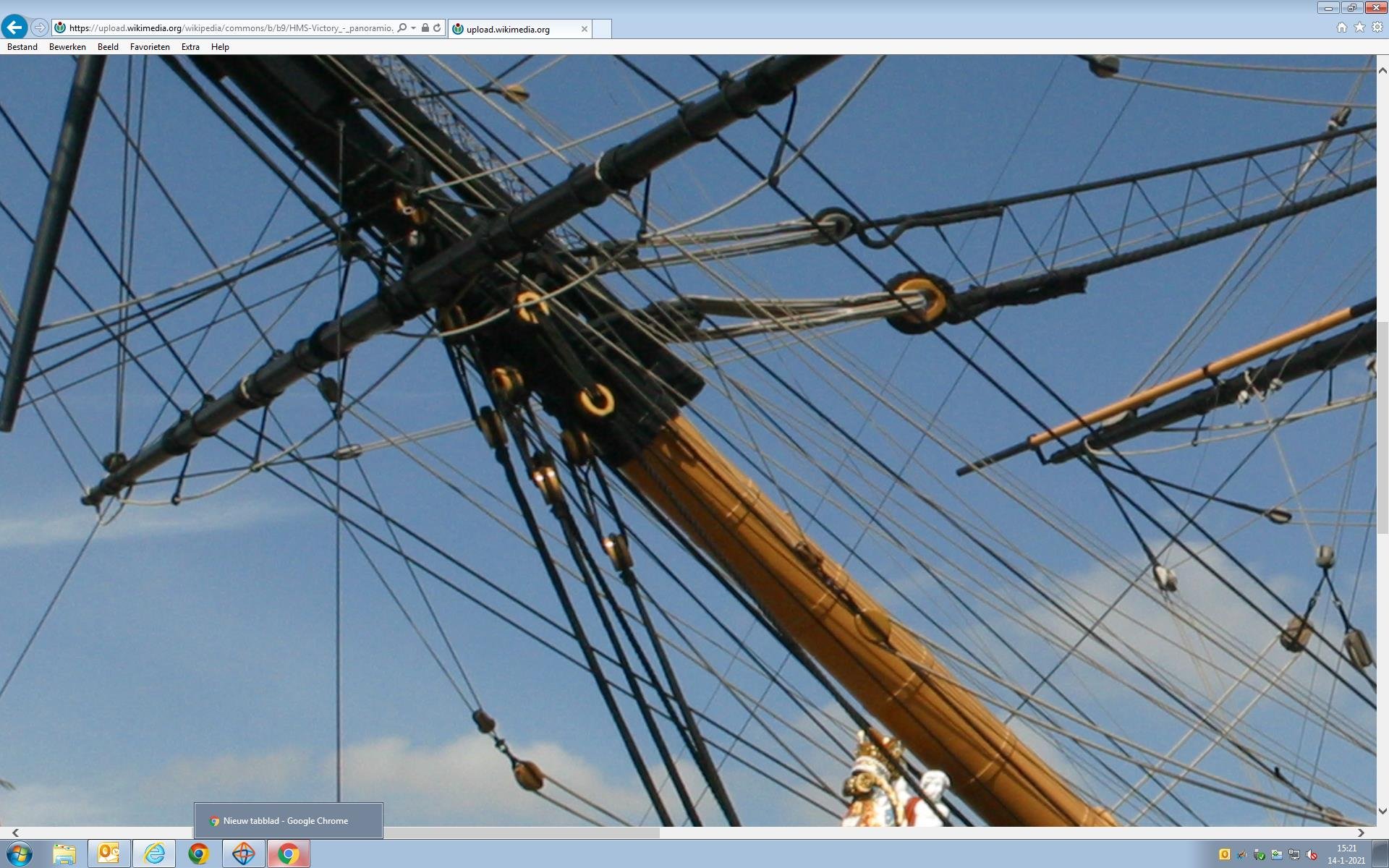
Some progress on the fore mast. The different parts (fore lower mast, fore topmast, fore topgallant mast, fore lower top, fore topmast top and hand mast) have been constructed. Again quite some sorting out, especially with regard to the sheaves that are let in the different mast sections. First view with the under side of the tops: And the top side of the tops and fore mast cap: The tops in detail. The crosstrees taper on the under side and the trestletrees ends are snaped and rounded. Sheaves for the main topgallant bowlines are put in the after end of the trestletrees. (the topmast trestletree of the main mast will have those sheaves in the fore end). The cap has four blocks. Aft/underneath for the fore topmast yard cluelines. The span in the middle for the fore lower yard lifts. The topmast has two sheaves (called top rope sheaves): the lower on the block, running diagonally from forward port face to after starboard face. The upper above the heeling on the opposing diagonal plan from the lower one. The sheaves had ropes to lower the topmast (acc. to Zu Mondfeld). . The topgallant mast has four sheaves: one top rope sheave just above the heeling, again diagonally starboard forward to after port. Other sheaves according to McKay, Next step: assembling the fore mast, and attach battens, check blocks and some other blocks
-
And I changed the iron bands, for them to be under the rubbing paunch: Should be okay now
-
A few modifications. Changing the blocks on the bowsprit from deadeyes to closed heart. (neither sounds nice in real life...) First how I seized the blocks; the challenge is to have a tight fit around the bowsprit and having the blocks in the right place. The first is already fitted. It takes some calculations to know the distances, but one knows the diameter of the bowsprit and circumference is Pi times diameter. A 0,25mm thread through the 0.40mm thread. Back at the right distances for the circumference of the block plus the siezing Block in a third hand with the thick thread at the back Tightening the knot Putting both ends in a alligator clamp Siezing the rope And the second block in place Now the third block and a slipping connections to tighten the rope around the bowsprit Both ends in clamps One end back to the block, as a loop, because it will be included in the siezing There is the loop: Tighten the rope by slipping the free end through the siezing, CA glue and cutting the end off.
-
Again I have to correct a mistake. The iron bands run UNDER the rubbing paunch. Easy to correct. Picture to follow.
-
What puzzles me on the picture are the steel bars on the picture and no sign of deadeye blocks. Are the bars used to fasten the shrouds? The battens run over the gunwale and taper towards the centre. I have added a plank on the aft side of the top, on which the stanchions will come for the rail and netting. Deadeyes glued in place. Painted several times. I added a lining on the port, starboard and fore sides of the top, like on the real top. The short side of the battens are thereby protected from damaging them. I will add the blocks, stanchions and netting later, but before putting the fore mast assembly together.
-
The Fore Mast: Quite a bit of sorting out. Unfortunately I made pictures without my SD card in the camera. So there is more result than process😕. Here the cheeks on top of iron bands, bibbs in place as well as the rubbing paunch. Filed grooves to accommodate the bands. Filled up the space between the bibbs and the rubbing paunch, very much like Lees draws it. More iron bands: Then the fore mast top. Crosstrees and trestletrees. Gunwale glues to the top platform. The tops were constructed using planks, plywood not having been invented in 1805. I planked the platform with 0.5mm planks, using two different widths, as per McKay. The planks "intersect" in the four corners. Next pictures shows some more modifications. The battens run over the gunwale and taper towards the centre. I have added a plank on the aft side of the top, on which the stanchions will come. The pictures I made of the grounded tops during my visit to Portsmouth helped a lot. One does not get very often the chance of seeing the tops so close-up:
-
Very nice progress Robert. Way ahead of my Victory!!
-
On another forum it was noticed that the deadeyes for the bobstays and shrouds are not period correct. They should be closed heart blocks. This is confirmed by pictures of the actual Victory and by McKay and Longridge. Lees mentions both options. As soon as they arrive from the USA I will change them.
-
Masting and rigging. I have a feeling this is nicer than building the hull. Less mass production and more smaller, single projects. There is some conflicting information, so I do some research for which I , apart from the manual use books by Zu Mondfeld, Rigging Period Ship Models (Lennarth Peterson), The Masting and Rigging of English Ships of War (James Lees), and The Anatomy of Nelson's Ships (C.N. Longridge) and of course pictures from the HMS Victory in Portsmouth. I will try to explain the choices I make. The bowsprit It started simpel: The bees Bee blocks for the fore topmast stay and preventer stay: View from above: The dowel sort of fits in the square hole in the cap, below the round hole for the jibboom. Cap fitted: Sprit sail sling saddle Gammoning fish with grooves to keep the gammoning in position. Lees and Zu Mondfeld both mention the fish (a long plank with grooves), but McKay doesn't, and the actual Victory doesn't have the gammoning fish but rather three saddles which are mounted directly unto the bowsprit. I followed McKay: I copied this technique from Middleton. First I removed less than halve of a dowel and then hollowed it out: Three saddles (1 bigger) The sprit sail yard saddle, the stop cleats and the jib boom support (from right to left) And the "iron" bands (heat shrink tubing) Painted, and the start of the jib boom: Flying jib boom Bowsprit, jib boom, flying jib boom, dolphin striker and flag pole: And the start of the standing rigging: blocks for the fore topgallant flag staff stay, the flying martingale, and outer and inner martingale. Deadeyes for the bobstay and shrouds. A bit of a challenge to get it right, but after some practice I was fine. Looks messy, but there is a system: Cheers, Paul
-
Thanks a lot guys for all the likes. Heinz, all you have to do is send me a personal message. The hull is finished😌. The poop ladder hand rail: And than the brass profiles. I followed both the manual and pictures. Not happy with the decorative scroll in the kit, and I made some myself: And in situ: Three of them: And painted: And an overview of the work so far. Next: the simulated front gun ports of the lower and middle gun decks. With a fine line of red ocre it became a bit more realistic Now masting and rigging. Paul
-
There was still a left-over thing to do on the poop deck: the signal flags. The signal flags which were used in 1805 were published in 1799 by Captain Sir Home Popham. The set of flags consisted of 10 numerical flags (1-10) and 5 other flags (preparatory, substitute, affirmative, finish and dissent). There was a 38 pages long book with words and their corresponding numerical code (e.g. 253 means England). This signal flag system was replaced by several others, until in 1857 it was supplanted by the Commercial Code of Signals published by the British Board of Trade. However, Nelson used a codebook which originally had a somewhat different set of flags than Popham's code, and which had been revised prior to the time of the Battle of Trafalgar due to the belief that the thin and signal flags had been compromised. Because there is some debate about which flags Nelson used, I used the Popham signal flags. I printed a complete set on transfer paper, which I then ironed on cotton (thin and smooth, called Poplin). The size of the flags is 7x7mm. Cutting and folding and then pushing them in the proper box of the flag locker: By the way, I'm not happy about the hammock netting of the starboard poop. Will replace it. Regards. Paul
-
The waist deck stanchions: Not much to say, except that I rounded the 1.5x1.5mm walnut strips on the deck. A bigger challenge were the guns on the forecastle. They are 12 pounders medium guns. Their position is clear, but how were they held in place at sea? I am pretty sure they didn't glue them on the deck... None of the books, nor the internet gave me a clear answer. Middleton put them at the forecastle gun ports, fully rigged. I decided to follow some other model builders and used the tackle to fix the guns. This is most likely a good solution. Lastly I added some eyelets around the (hole of the) mizzen mast. I may need them later when rigging. And a global impression Paul
-
The two sheet anchors have palm blocks on top of the waist capping. The ones in the kit are a bit too simple to be realistic, and I modified them: The bower anchor palm blocks will follow. Paul
-
The anchors. This took quite a bit more time than anticipated. First smoothing the surface of the metal. Then gluing the stocks, with the anchor in place. This leaves a very small gap between the two halves of the stock, which, according to Longridge, is correct, Next fitting the bands. I used heat-shrink tubing (used in wiring). It helped a lot to achieve a tight fit. Gluing stock to anchor, and several coats of dull black paint. The rings with black thread as puddening and white extra's. And the finished product: Note the simulated rivets. Paul
-
Gradually I am moving to the completion of part 1, the hull. First the rudder: attaching to the stern post. I made sure the pattern of the copper plates continued on the rudder. This, however, although visually appealing, may not be historically correct. McKay draws the plates like this: No relation between the plates of the hull and those of the rudder. However, I leave it like this. The damage may be bigger than the correctness. The rope between the chain and the mizzen channel serves to operate the rudder in case the original steering mechanism fails. Lashing of the hook and seizing the rope. The rope is too light to "hang" nicely. I inserted a very thin, easy to curve wire in the rope. I guess that did the trick. Paul
-
Hi Tracey I took an image from the internet, photo shopped away all colours, and replaced them with brown and yellow only. Then I printed it several times on decal paper. Maybe the following attached image helps:
-
Thanks Nate, Robert and Mr Iceland. It's been a while, but it's getting colder and darker in Holland, so there is some progress on the Victory again. First the guns. Or actually the dummy barrels. The challenge was to get them all at the same height, and level. I made a small metal jig, width of the gun port, with a hole at the right height. I put the drill bit through the hole, after fitting a spirit level on the drill. This is the result: Next the rudder. Following the advice by Middleton, I raised the notch at the back of the rudder, in order for the spectacle plate to be above water level. Fortunate I had a picture of the actual rudder in Portsmouth, allowing me to copy some details. Above the spectacle plate there are two pieces of metal, one against the rudder, the other separate and rounded on top. I added those as well. Additionally I added 2 eyelets on the spectacle plate to accommodate the chain. Coppering the rudder. After doing all this I realized that if the front edge of the rudder and the rear edge of the stern post are both flat, and flush against one another, the rudder has no way of turning (that is, in real life). A close look of the real rudder shows that the front edge of the rudder is pointed. That make a lot of sense. I decided to cut the front edge of the rudder and make it more pointed. You can see it here on the finished rudder. That left me with fitting the hinges and rudder straps on the rudder itself. The straps on the hull will follow. I used small nails, used for model train rails, for the straps. Cheers, Paul
-
Then the gun port assemblies. I finished the lower gun deck gun port assemblies on the starboard side. First I had to thicken part of of the gun port lids in order to follow the thickening of the wale, when closed. The gun ports lids are all different that way. The gun port lids of the lower gun deck have scuttles. The hinges are glued on top of a veru thing piece of styreen to indicate the scuttle. On the inside of the scuttle there is a latch, to keep the scuttle closed. I used two eyelets and a short piece of brass wire to mimic this. Before fitting the gun ports, I glued the rigols in place, after blackening them with brass black. According to the manual one is supposed to glue the upper end of the hinges directly unto the hull. This I found less appealing because there is no knuckle to be seen. I decided to use a bend nail and glue it to the hinge. Then it was just a matter of drilling two holes in the hull, and glue the pins in place. The gun port lids shown are from the middle gun deck. Then the ropes to open the lid; two for each lid. Or are they called chains?? To mimic a splice I followed the suggestion by Middleton. I thought that just drilled holes in the hull to pass the rope through is not historically correct. Therefore I punched styreen rounds to mimic the disc on the hull of the real Victory, and, using 0,5mm silicon tubing used in recreational angling, I mimicked the protective tubing.
-
Following almost one year of relative inactivity (in terms of building the Victory☺️), things have started again. First the channels and chain plates. The channels are lined with styreen half rounds and the studding sail boom bracket and support are fitted as well as the channel support brackets. It is important to observe the direction of the chain plates and the dead eyes. The chain plates have to be lined up with the shrouds. Also the dead eyes should be rotated in the right position: the eyes of the lower dead eye (fitted now) should be positioned directly opposite the eyes of the upper dead eye (the one which connects to the shrouds). In that way the forces of the shroud will be evenly distributed. By putting a thin ribbon from the position of the lowest top over the dead eye the direction of the chain plate and the position of the eyes in the dead becomes clear.
-
Thanks Mort. I bought the sheaves on-line in Holland: but I guess you can find them in any good shop for ship modelling. A small addition regarding the chesstree: I found this picture on a Dutch ship modelling forum. It confirms what Frankie mentioned: the chesstree is mainly, or purely, a fairlead for the Tacks (chesstree is halsklamp in Dutch, eeuw means century).
-
I have to make a correction, following some discussion on Kevin’s log. The chesstree has nothing to do with lowering the anchor but has a sheave for the main sail tack, which then passes through a sheave in the hull, and then to a giant cleat on the gun deck. Apparently the forces on this tack were enormous, and the chesstree was therefore very heavy. Fortunately I have included all the appropriate sheaves😅