
HOLIDAY DONATION DRIVE - SUPPORT MSW - DO YOUR PART TO KEEP THIS GREAT FORUM GOING! (Only 53 donations so far out of 49,000 members - C'mon guys!)
×


paulb
-
Posts
117 -
Joined
-
Last visited
Content Type
Profiles
Forums
Gallery
Events
Everything posted by paulb
-
You’re quite right Frankie, about the chesstree. Thnx.
- 1,319 replies
-
- 5
-

-
- caldercraft
- Victory
- (and 1 more)
-
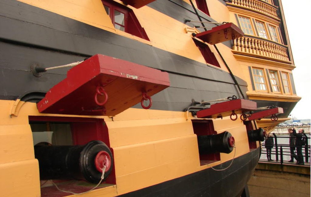
Hull details Next are the side entry, with steps, the fenders and chesstrees. The painting of the side entry port was a nice painting job. I covered the passage with walnut. The steps were somewhat of a hassle. It was only now that I found out that the lower gunport pattern was placed too far towards the stern, No idea how that happened. Anyway, I had to shorten the steps to make them fit nicely. Another problem was the distance between steps. In order to get the right step near the side entry I had to make the distances of the lower steps a bit bigger than the upper steps. Unfortunately the elm tree pump tube lining was not in the black section. Also the fenders can be seen here. The chesstrees serve as a protection of the hull when lowering the anchor. In the Caldercraft kit it is curved on the outside in order to follow the curve of the hull. Both McKay and in the original Victory the outside is straight, so that's what I did. Additionally I noticed that in McKay and in the manual the chesstree butts up against the underside of the waist capping rail, unlike the situation on the original Victory. I decided to follow McKay. I included a sheave to accommodate the tack. Next: the port side
-
Don’t worry Jerry, you’re in the clear. 😊 See post 899 of your log. Paul
- 1,319 replies
-
- 3
-
-
- caldercraft
- Victory
- (and 1 more)
-
Yeah, that’s the one. You can find it on the same wooden sheet as the other chesstree and the fenders. It’s there to protect the hull when lowering the anchor. Good luck.
- 1,319 replies
-
- 2
-
-
- caldercraft
- Victory
- (and 1 more)
-
Very inspirational, Nick. I like your attention to detail. A great example for my own build. Paul
-
Very neat and clean, Robert, nice work, Paul
-
Hi Kevin, Been following your log and I'm most impressed. Thank you for the beautiful pictures. One question: I am presently working on the chesstrees, and I couldn't help noticing that yours seems to be missing on the port side of the ship. Is that on purpose? The original Victory has chesstrees on both sides... Otherwise: lots of respect! Paul
- 1,319 replies
-
- 3
-
-
- caldercraft
- Victory
- (and 1 more)
-
HI Mort, I'm glad you like my build. Unfortunately I can't find yours on MSW. Would like to see it. About the stern: yes, the stern fascia has 2 blades, the first one is mounted quite early in the process. The outer fascia I prepared completely on my work top, and then glued it onto the inner one, but I added some styrene strips to mimic the striped pattern on the sides. If I understand your 2nd question correctly: yes, the rear edge of parts 105 and 106 are flush with the gun port patterns. In that way the inner stern fascia remains straight (as does the outer one). I hope this answers your questions. Good luck with your Victory project!
-
Quarter Galleries The quarter galleries indeed. And I thought the bow was difficult... I started with the starboard gallery. It was only now that I realized the lower three window frames were sloping up towards the stern. After doubting for a long time I decided to cut out the lower windows, and refit them, starting on the port side. And refit this panel and redo the strips and paintwork Now the same process on starboard. The gallery on starboard has also been changed
-
Stern Fascia Thanks for the nice comments. Later than expected an update,Rich. I finished the work on the Stern Fascia. Lots of details, especially the trophy of arms. Let's start at the beginning: fitting the window frames. I followed the suggestion of Gil Middleton: "Placing the windows from behind (opposite from instructions) gave much better definition to windows." Therefore I cut out the rabbets at the back of the sheet (the non-exposed side): The result: Global painting: And painting the loose ornaments and gluing them: Next: painting of the Trophy of Arms : roughly the black and white: and more detailing and gluing: The black rectangles between the window frames are cut from styrene strips and painted black. This gives well defined edges. I decided to copy the HMS Victory as good as possible, so I included the striped black/yellow pattern on the sides of the stern fascia I used 0,5mm styrene strips, and painted their sides in the right colour: to get this effect: The end result: About some details: some edges above and below the baluster patterns have been thickened with quarter round strips. This gave the whole thing a bit more body. Additionally I included 4 eyelet below the baluster patterns. You see them on the present HMS Vistory. Next project: the quarter galleries
-
I was not happy with the clumsy skylight which came with the kit, and so weren't some of my Dutch forum friends. Decided to make one from scratch. I made a small cage from 3x3 and 2x3 walnut. On top strips of 0,5x3mm. The window frames I made from styrene, which I painted black, the skirting are styrene as well, painted brownish. The window frames on top I made from photo-etch scrap material. And some merciless macros.
-
Thanks Graham and Heinz, it's a pleasure. Time for an update of the Poop Deck. Time-consuming work, but fun doing it. First I spent some time figuring out what the flag locker looks like. Fortunately "HMS Victory, 1765-1812 (first rate ship of the line) Owners' Workshop Manual by Peter Goodwin, has many nice pictures, one of them showing the locker: I like the Roman numbers, probably indicating where the signal flags were supposed to be stored. They used the Popham signal flags, each flag signifying a number from 0-9. Another feature is the covering of 4 holes, where the outer transom knees appear. This is my version of the locker, flags will follow: The overview of the Poop Deck shows a few modifications from the manual: - the timberheads (the ones that stick out) should be round, rather than square, and should have a sheave. - in between the inner transom knees, at the bottom, there should be an extra piece of timber, holding the flag mast. - the outer edge of the Poop is constructed in a certain way, which is not very clear from the manual: This is the original. The edge of the Poop runs straight, but the moulding runs from the quarter round edge aft and upwards to meet the Poop edge behind the deadeyes. I tried to (sort of) copy this structure: Next: the skylight. Contrary to the manual, the skylight has a rounded roof, which follows the curve of the deck: As you can see I added 2x2 sheaves in the Mizzen Topsail Sheet Bitts. This required 2 newly made bitts from scratch, as the original ones were too thin to accommodate the sheaves. Then the fire bucket assembly. The Poop Deck Barricade Rail follows the curve of the deck. I followed the suggestion of Gil Middleton and first glued the buckets to the decorative beam. The beam provided by Caldercraft is hardly decorative, and is too short (it fits between the Poop Ladders). Originally the beam runs along the whole Poop plank sheer, as one can see here: I know, it is risky to compare the original ships with macro's of the model. Please ignore the dust. The buckets were made brownish with Krick Brass Brown fluid. In some pictures on the internet the buckets are brown, in others black. I used decals to put the King George Monogram on the buckets. The yellow was completely transparent on the decal, so I put a bit of yellow paint on the bucket, and then put on the decal. For the fire bucket handle I used two brass eyelets and 0,25mm black rope. Finally I glued the Poop Ladder Assembly in position. Next chapter is the Stern Fascia.
-
For anyone interested in the HMS Victory: I found a half-hour video on YouTube of a walk-through. It gives one the opportunity to check on details, without having to go to Portsmouth. The bonuses are images of the Captain's Cabin and the Poop Deck, both of which usually are off-limits to the general public. Disappointingly the flag locker on the Poop, which interests me at the moment, was removed . The link:
-
Poop Deck Before starting with the poop deck, I finished some details of the bow and the forecastle. The connection between the cat-head support and the first rail. I had to remove quite a bit of wale to obtain and good fit. The 90 degree curve I made by softening the wood with water, and then left it to dry in a jig. The curve around te hull was done using heat. The blue strip is made from styrene. The main top bow line bits and fore topsail sheet bits were modified to look more like the ones in Portsmouth. The former has to have two sheaves, the latter three sheaves. Both were made thicker below the bits. First the original. Now the work on the Poop Deck can start. Planking the deck is basically the same as the other decks with a 5 plank system. The main difference between this deck and the others is the tapering of the poop towards the stern, while none of the other decks have significant tapering. I used the drawing by McKay and Longridge to help with the planking. In case of a curves or tapered deck the planks should not be cut away to a sharp point. Instead the planks should be "joggled" into the margin plank. This is how McKay draws the poop: If you look at the margins of the deck, you may notice that none of the planks end at a width less than half their original size, and margin plank is one piece of timber, somewhat wider than the other planks. This what I made of it:
-
Some more work on the bow and catheads. If I thought the bow was a challenge so far, I have to think again. Especially painting the figure head took a long time and many corrections. Partly it's because of my clumsiness, but also the detailing by Caldercraft is poor. That mostly applies to the coat of arms and the flowers below it. Another thing they could improve upon are the Cherubim and Seraphim. The original are (somewhat) chubby small boys, but over the years they have grown to be young man (Caldercraft must have thought). Additionally it took quite some filing to detach the arms from the bodies. I modified the catheads slightly by making them a bit thicker (horizontally) and by including three brass sheaves. Okay, some pictures: First the beak head platforms and stools: the knight-heads in position,each with a pin to attach the boomkins. The pillars of the marines'walk are also in place. That turned out to be a little problem, because they are supposed to be positioned flush with the forward face of the third head timber, but there it found the previously glued pieces of walnut, Some filing of both pieces solved the problem and gave a very sturdy connection. Then the figure head. Though on the picture it all seems to be the same yellow paint, in reality the yellow in the figure head is gold paint. The strings of the harp couldn't be painted, they are too thin. I used 0.25x4mm styrene strips from which I cut very thin strips, which I glued in the harp to mimic the strings. The catheads: and view from the main mast, with the marines' walk in position: That leaves me with the connecting strips between the cathead knee and the upper rail, before I can move to the poop deck.
-
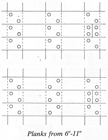
Saw your planking just now. Beautiful!! I like the fact that you used individual, short planks, rather than those as long as the ship itself. I regret having done the latter. Coppering: always a good subject for a discussion. Of course it is historically more correct to copper. At the same time the caldercraft copper plates are not correct... IF you decide to copper, I would suggest you use an overlap of 1/3 between the rows, instead of 1/2 as suggested by the manual. This is the diagram by McKay: By the way: coppering of their ships gave the English the most important advantage over the Dutch in the trade with the East. It made their ships much faster (due to less fouling) and maintenance was easier. The Dutch thought investing in coppering was too expensive. Another reason was that the Dutch harbours were not as deep as the English, and therefore the ships (and the copper plates) were vulnarable to damage. Anyway, it did not help the VOC (unfortunately..)
- 527 replies
-
- 1
-
-
- caldercraft
- victory
- (and 1 more)
-
Bow Building the bow was more of a callenge than anticipated. It took me way more time than expected, especially because of a number of part which I had to make from scratch over and over again. I started with the timberhead. This one is not square like most timberheads, more more like a pentagon. In order to do this, the timberhead had to be made thicker first. and filed: The placement of the four head timbers: and placing the lining planks: Then it was time to place the bow main rail plaatsen, and making sure it fitted snugly against the hull (aft) and the roundhouses (fore). And finally the finishing of the timberheads: Additionally I fixed the hawser holes: By far the most challenging part so far of this model, but I guess some more challenges will come.
-
The blocks I replaced because I found the caldercraft ones not very realistic. Most blocks I replaced with blocks from Clasicmodel.com (yes, with one s). I bought the 2mm blocks from Syren Shipmodel Company. The caldercraft ropes are a bit fluffy and there are no cable-laid ropes for the breech ropes, for the anchor rope and for the shrouds (although there is some discussion whether shrouds should be cable-laid or shroud-laid ). I replaced them with Morope rope (about one kilometer of rope), which is very nice to work with, although you must take care, using knots or CA glue, to prevent unraveling.
- 527 replies
-
- 1
-
-
- caldercraft
- victory
- (and 1 more)
-
I agree with your comment about the Caldercraft walnut strips. They certainly are brittle. Strips which are much better are available, but after replacing all my rope and blocks, I did not feel like replacing all the strips as well. Your planking, by the way, is suberb!! On a Dutch forum there was a lot of debate about the lower rabeted stop of the gunports. On the present HMS Victory there is none, and from McKay's drawings it is not clear. I decided to omit them, although the Caldercraft manual says otherwise. We may never know what it was like in 1805.
- 527 replies
-
- 5
-
-
- caldercraft
- victory
- (and 1 more)
-
Just to add a small comment about tree nails: this is how Zu Mondfeld in Historic Ship Models describes tree nailing. Most model builder ignore the tree nails, except the ones at the end of every plank. (I must admit I ignored those as well ). It all depends on what you think has the better looks.
- 527 replies
-
- 1
-
-
- caldercraft
- victory
- (and 1 more)
-
Great start, Mobbsie. Judging from your work on the Agamemnon, this is bound to be another excellent project. And I mean both the result and the process. Cheers, Paul
-
The carronades took more time than expected, especially to make them look more or less authentic. First I had to improve the die-cast which was in the kit. Some imperfections had to be filed, and the elevation thread was not complete and in the wrong place. The barrel was closed, so I drilled it for a more realistic look.For elevation thread I used 1mm micro-bolt, with a M1 brass ring. I included handles for manually elevating the barrel. Finally I elevated the deck block on four corners as per the present arrangement on the HMS Victory.It now looks like this: Tackle was not unequivocal. McKay mentions one breech rope en 2 side tackles (one on each side). Zu Mondfeld however decribes 1 breech rope and 4 side tackles (2 on each side). The carronade has no train tackle.I followed the suggestions of Zu Mondfeld. The breech rope is cable-laid.
-
Forecastle Some more work on the Beakhead Capping Assembly.I made a few adaptations, based on the drawings of McKay:The "plank sheer" (the plank with the timberhead locating holes) runs more lateral according to McKay. Additionally, there are 3 eyelets (iron rings) on both sides.Furthermore six out of eight timberheads have sheaves, I have included them. Also the forecastle snatch block should have a sheave. All the sheaves are brass, with a single coat of glossy black paint. Now, it seems the starboard roundhouse is skew. Fortunately in reality this is not the case. Must be the camera. The somewhat long timberhead (on the port side) is real, unfortunately. I will leave it like this, as improving it may actually worsen the situation.
-
Some progress on the Quarter Deck: mast sleeve, steering wheel assembly and binnacle. And some work on the beakhead and roundhouses:
-
Real nice work Robert. Good to see the progress, after being "out-of-forum" for a while. It's very inspiring! Paul