

Mark Pearse
-
Posts
698 -
Joined
-
Last visited
Content Type
Profiles
Forums
Gallery
Events
Posts posted by Mark Pearse
-
-
Thank you for the interest, the encouragement helps.
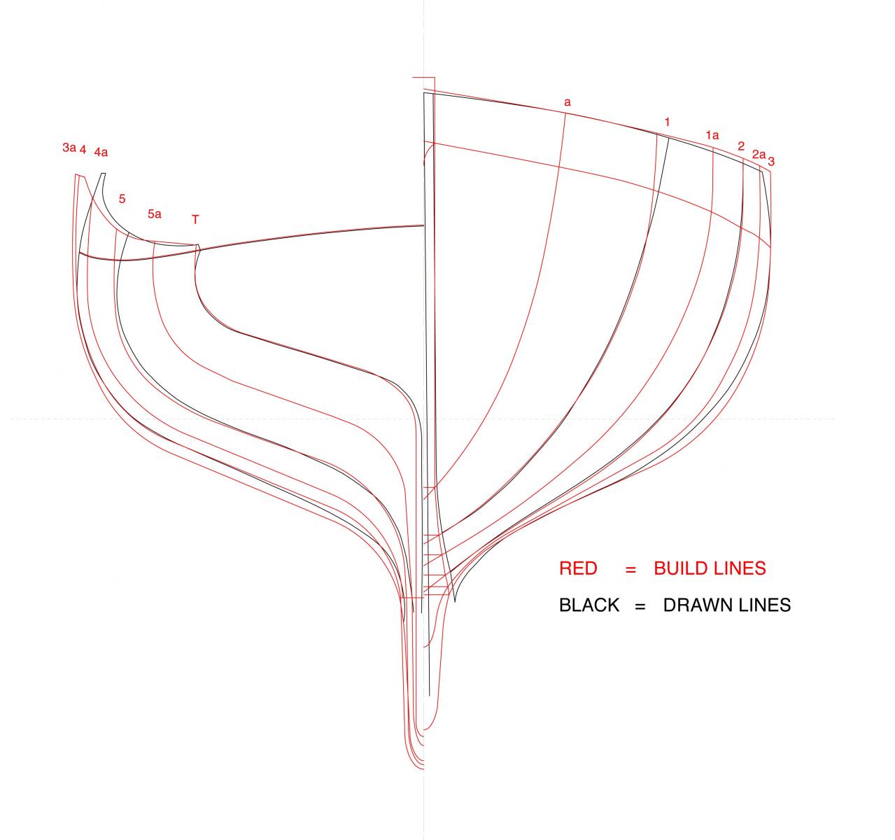
I've pretty much worked up the lines now, adapting them in the way that the lines of the original Ranger was adapted for construction. Below I have laid the drawn & built lines of Ranger to make this change clearer.
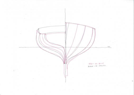
They are pretty close but vary in the amount of tumblehome (less as built) & the water entry (finer as built). I wondered why they had reduced the tumblehome so much, & I asked a boatbuilder about whether it's more difficult to plank than a fairly vertical face & in his opinion they were not so different in difficulty. He felt that the probable reason was when they set up the stations to start building they didn't like the look of the tumblehome. It doesn't really affect the underwater shape. The water entry is something I'll have a go at & possibly change the lines, possibly not, Sydney Harbour can be terrifically choppy, so that's an obvious reason for the change. The question is whether I am able to vary the lines or not. I'll try & see what happens.
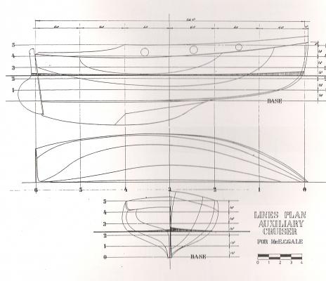
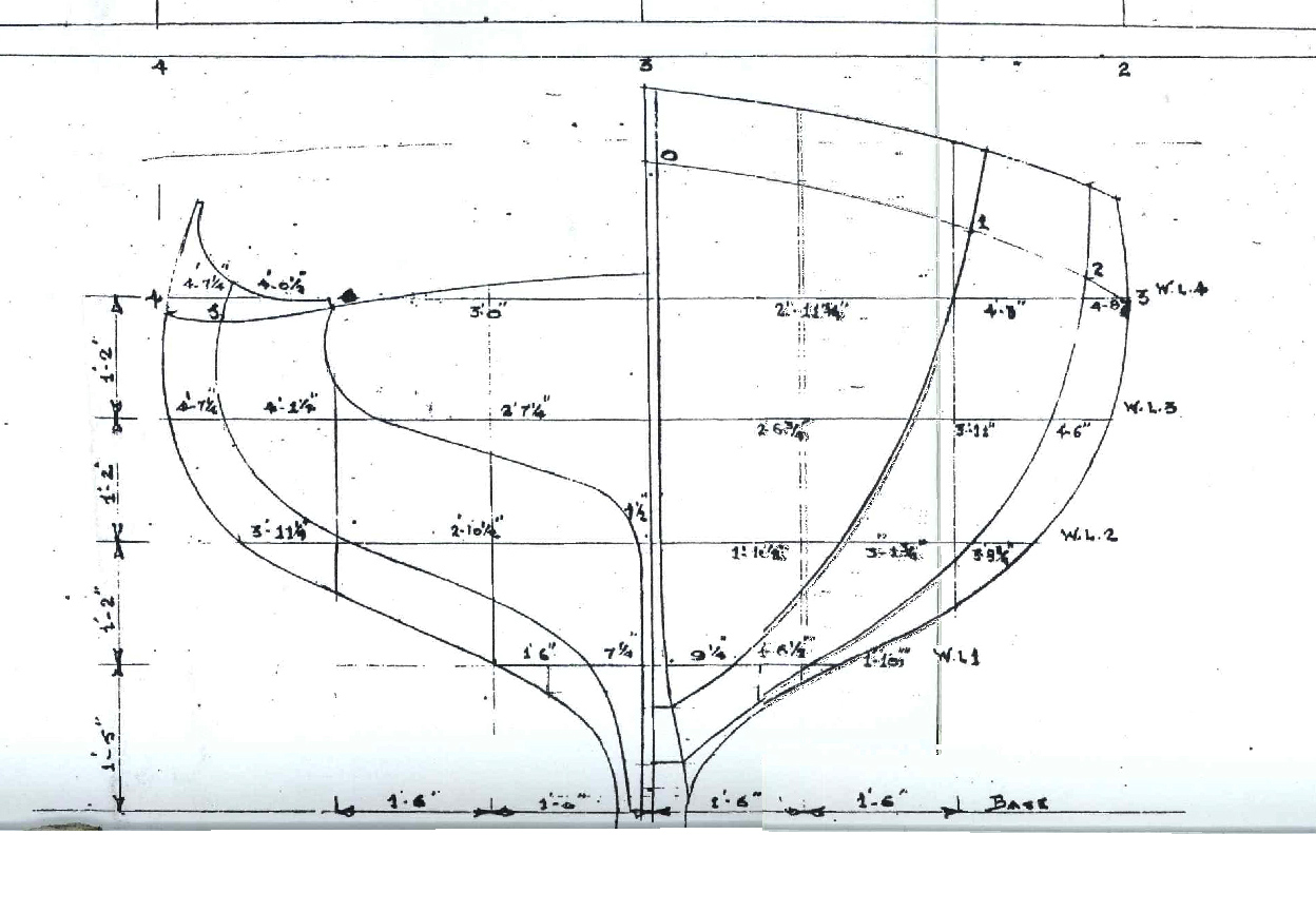
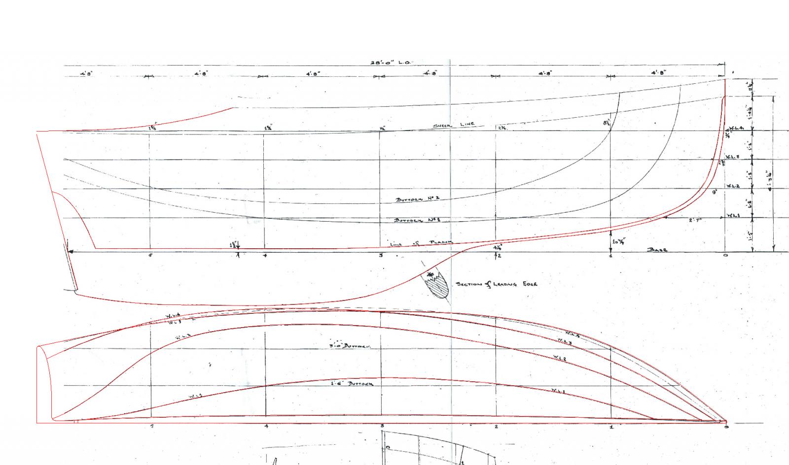
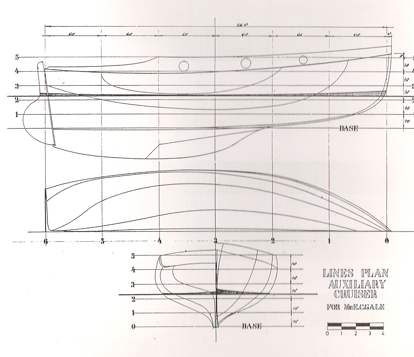
This is the lines drawing of the 28 footer, the similarities to the drawn 24 footer is clear, the general roundness of the topsides aft of the midships.
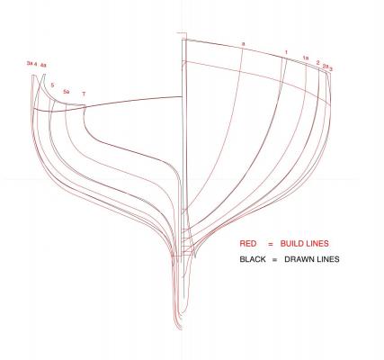
This is the lines I've worked up, plus a version which also shows the drawn version overlaid with the build version. A big difference is the midships lines, which are very round as drawn & less firm, all I can say is that the lines I drew (station 3) are a better match for the original drawn lines (plan drawing) than the original lines for station 3. The transition to the lines aft will reveal what does work - a job for the carved shape. I also am inclined to go for the firmer shape because as a yacht they are fairly lightly ballasted & get quite a lot of their righting moment from the positive buoyancy of the hull shape when heeled - the beaminess, firm midships shape.
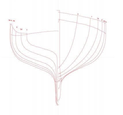
This is the side & plan view of the 28 footer, the station lines were removed as they obscured the drawn lines.
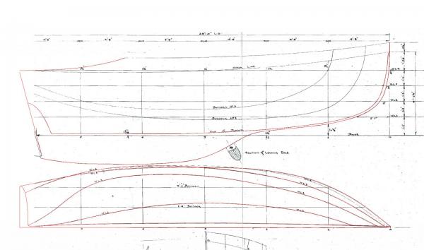
Next step is to review the lines again, then work out a setup for the plywood stations once they are cut, then cut them. Also start looking at the keel construction, particularly in the stern area where the bilges are very narrow & deep.
thanks
MP
-
-
I plan to build a 1:12 model of a 28 foot yacht. This design has never been built, but is a variant of a 24 foot yacht design usually called ‘a Ranger’ (see Wooden Boat magazine issue 227). The first of the type was called Ranger, launched in 1933. They are popular & loved because the design fits the purpose so well: day use on Sydney Harbour, with short coastal trips & overnighting capacity. The design was adapted by the designer to a 32’ ocean-going variant, & also a 28’ ocean-going variant. The 28 footer came 8th on IRC handicap in the 2006 Sydney Hobart Race (see youtube video of her in 2012 in 30-35 knots http://www.youtube.com/watch?v=Dd9LqrDP510). The design I will build is slimmer & with less buoyancy in the bow than the ocean-going 28 footer.
The ‘Ranger’ yachts are generally 24 foot (7.3m) waterline & on deck, with bowsprit, gaff rig & a raised deck. They are very beamy at around 9’6” (2.9m), or a beam/length proportion of about 40%. This version is 28’ & 9’6” beam, so it’s basically stretched, not scaled up.
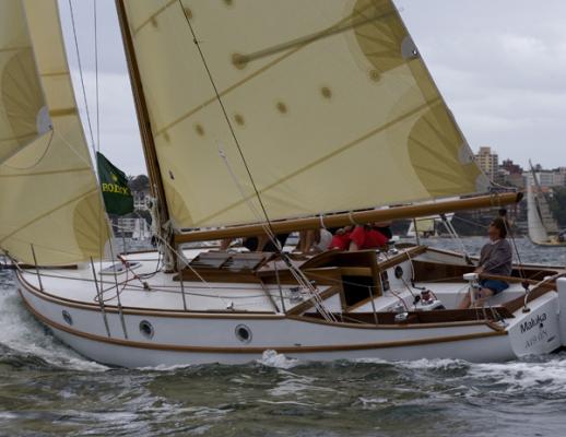
This design is of interest generally because: the smaller ones are admired & loved, at least locally; this 28’ design has never been built; the designer (Cliff Gale) was a self-taught boat designer & in his day was considered one of Sydney’s best yachtsman. But it’s also personal: I’m lucky enough to have one of the 24 footers. I love the design, that they can be so beamy yet look good & sail so well, & they are a terrific motor boat as well. They sail well in 5 knots & can also sail unreefed in 40 knots.
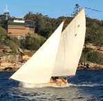
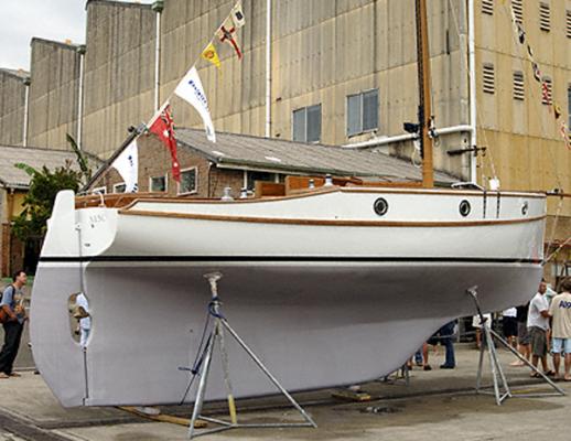
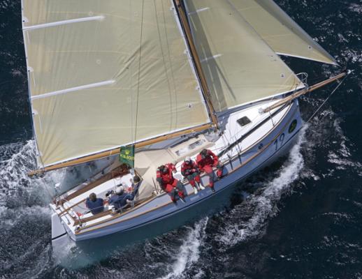
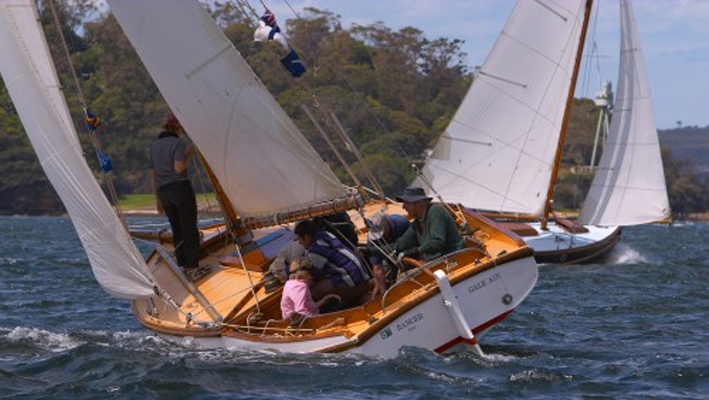
These photos show well the nuggety shape:

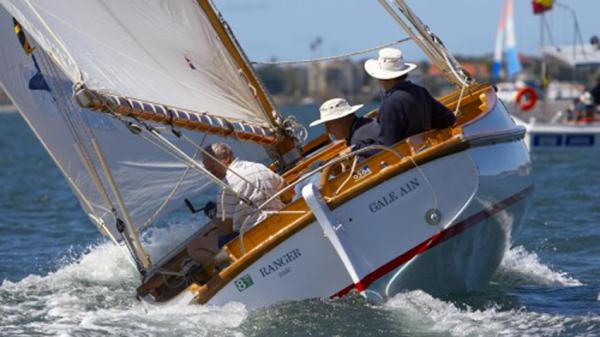
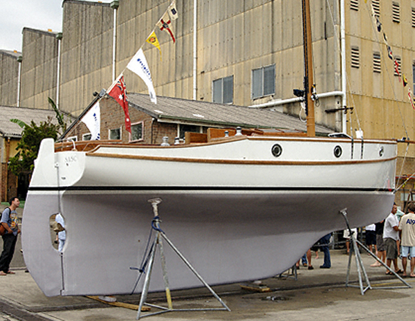
This is the existing ocean going 28 footer, she's the most similar boat to the design I'm building, but much fuller. It's a big little boat:
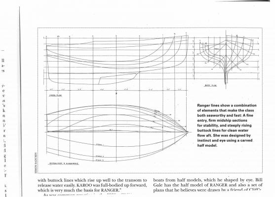
Cliff Gale was a self-taught designer, who learned by towing carved models behind a dinghy. Ranger was designed by carving a bread & butter half model, which was taken apart & measured. Cliff’s son Bill recently wrote this about his father:
"Cliff Gale left school in 1898 aged twelve, & knew arithmetic but had insufficient mathematics to be useful in boat design. As a boy he lived at Woolwich & the family owned a rowing skiff for transport & pleasure. From thirteen to nineteen he made in excess of one hundred rough sailing models, each one progressively different, which he tested from the skiff. At nineteen he felt he had completed his design self-education.”
I would like to build the model plank on ribs, & possibly make it RC sailing - although plain sailing is an alternative as well. But I’ll leave that alternative open until I get to that point, I will also be happy if a nice display model is the result.
The issue that needs to be resolved is actually what to build... I do have the original drawings as done by a naval architect to Cliff’s design, but having looked carefully at them, they do not relate accurately between the different drawings. The history of the Ranger design makes this even worse: for Ranger herself we have Cliff’s original half model, we have the original drawings done from the half model, & we have lines drawing of Ranger meticulously done by 2 local shipwrights … & they don’t match up.
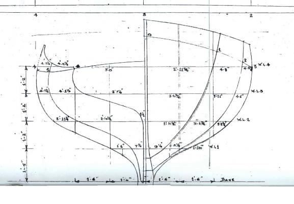
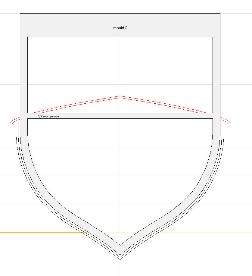
If you compare station 4 on the drawings below, the design drawing shows more tumblehome, & much less buoyancy - the volume below the waterline was increased while being built, to increase her load-carrying capacity:
Bill Gale tells me that his father went to the boatbuilder often to supervise the construction, & that he made a number of modifications to the lines while she was being built.
For the model, I will have to adapt the lines drawing, trying to do it in a similar way that the lines drawing of Ranger was adapted to the built design. Because of the uncertainty, the model building method needs to help resolve thoughtfully these differences between the various possible shapes, & not be a way of getting caught up in plotting lines on a screen that fit but might be going away from the design. Initially I spent some hours trying to resolve a set of lines that is consistent, as they do not quite match up on the original drawing. My CAD skills are fair but you can’t really see a subtle 3D curved object in a drawing, so making changes to a curve on screen seems risky in this case. So I’ve concluded that I must see the shape in the flesh, & so carve the solid hull shape, based on a set of lines I adapted from the original lines drawing. The shape will be fair, so then I know the molds will work. If the method is too difficult I will be reluctant to make corrections, so it needs to be fairly simple & easy to make & to change.
In putting this up early, I hope to benefit from the knowledge & experience of this forum. So I’ve done some sketches below that show the idea for my construction method, & hope that I can get some constructive criticism & help to iron out any issues now. In a few weeks I’ll get back to the computer & finalise the lines drawings; but for now I’ll describe the idea for the building method - as I see it now.
1
Work up a set of lines in CAD, from the original drawings.
2
Cut plywood molds from the station lines.
3
Assemble the molds with solid balsa blocking between them, the balsa blocking is to be removable. Possibly brass rods inserted at angles through the balsa & molds.
4
Carve the hull shape out of the solid, using the molds as indicators. If I need to add to the molds, glue strips of timber on the mold edges.
5
Make the stem, forefoot, keelson, keel, transom etc, to sit neatly over the hull shape.
6
Remove some of the solid blocking, where the ribs can sit directly on the molds; leave the blocking where the ribs want to lie at angles, I’ll probably need to put in temporary spacers to help hold the model together. By keeping blocking in the bow area, the ribs can follow their natural line rather be pushed into being straight across the hull. It's not so bad for the aft 2/3s of the hull shape, I think they'll be able to sit on the plywood ribs.
7
Cut the rabbet, rib the hull.
8
Plank the hull.
9
Remove molds & remaining blocking, progressively putting in some deck beams as it goes.
10
Have a cup of tea
thanks for reading this, I hope to learn a bit more before starting, & maybe revise the method if needed
MP
-
HI Michael,
That's exquisite timber; is that glue oozing out cross-linked PVA?
I had a nice putt-putt & the flywheel weight was obviously important to it's smooth & slow running. But isn't the weight of yours going to be proportionately quite tiny in scale? This will present a challenge. If the scale is 1:8, the weight will, I think, be 1:8 cubed or about 1:500 … ?
Is this one 2 stroke?
-
Hello Michael
could you say a bit more about the way you propose to use ribbands in the construction (how many per side, & is there any special issues with the setout)? I am still deciding myself on a method & this would help, as the scale, size & appearance are similar enough to my future project to be really useful. Are you doing it this way so that the ribs can rotate with the planking line rather than just all 90 degrees to the keel line?
thanks in advance
MP
-
Hello Jim
All very interesting & enjoyable, I hope to start a build soon & as a novice this is very helpful to see your method. Have you seen Jack Earl's log of the Kathleen Gillet voyage? There are some beautiful drawings of luggers, some up on the slips. thank you, I look forward to following this
MP
-
-
I like the way you have scaled the paint finish - it seems that glossy topsides in a scale model need to be a bit satin to look right. If you look at a 1:1 yacht at a distance it's very hard to see evidence of gloss.
amazing work
-
Hello Pete
I only recently saw this build, looks great. My question is on the scale, as I saw then photos of her sailing: I plan I build a 1":1' scale boat starting soon, & hopefully she will also sail ok as a pond boat. Did you adjust anything to get her to work as a working (scale) sail boat? Not sure if the question is clear.
Thanks, MP
-
Yes, like a Colin Archer but with a transom, really lovely. I look forward to seeing what unfolds.
-
Hi Spencer
I'm pretty conversant at CAD so I'm sorry of some of this is technically a bit complex. I'm going through the same thing - except that I use CAD a lot in my job so I know the commands fairly well.
My first step was to scan the plans I have of the yacht & them insert them as jpeg files into the CAD drawing. The original drawings were too large in area to scan in one go, so on screen I had to rotate & line them up etc in the CAD file. Put the scans on a separate layer (named jpegs, for example) as you want to be able to turn them on & off; they can also be a cause of programme crash so being able to turn them off when not in use will reduce this problem.
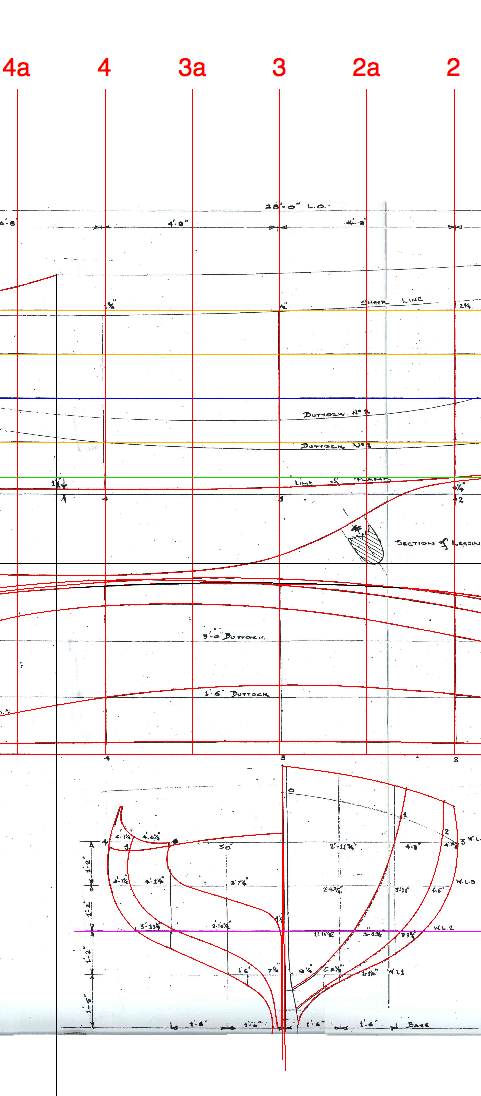
I started by drawing in the setup lines (horizontal lines, station positions etc), using the lines on the drawings (the horizontal section lines, whatever they are called), & I coloured them yellow, except the LWL blue & one green one. The partial view below shows some of that. The numbers are the stations, I'm adding in additional ones - the "a" numbers. Stations in red.
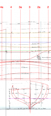
Most programmes will have a polyline function & a number of alternative ways of doing a polyline. The one I use is where you click a series of dots on the curved shape of a hull section & the programme will automatically join them in a "best fit" curve that goes through the points you have clicked. You can zoom right in & click a lot of points if you are sure the drawings are accurate. For me, the drawings I am working off have a lot of poetic license so the correspondence between the plan, side view & sectional shapes is a bit off.
The short vertical pale blue lines were checks - checking the plan drawing against the sectional shape.
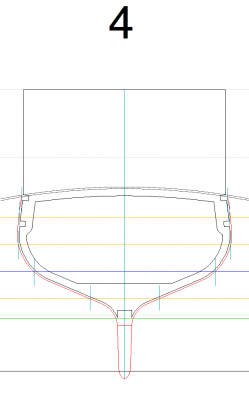
You should be able to tweak the polylines, but it's a fiendish task, I recommend printing pages off & sketching with a pencil to help make adjustments & then do it on screen. I then offset the final polylines by the planking thickness. On the drawing below the red represents the outside planking line & the black the mould shape to be laser cut from plywood. I will have to redo this as I'm going to build it a slightly different way, but the gist of it is there. Station #4 is shown below.
CAD programmes are pretty big, lots of commands, but you will only need maybe 10 or maybe 15 max. If you are going to work off paper prints that would simplify things, but I will need files that a cutter can read so I have to assemble lines into a connected shape - the mould shapes are one continuous line each, but that's starting to get difficult.
The conclusion I have reached is that if I make the plywood forms NOT part of the final build then I can make adjustments when I set them up - shave off as needed or add laminations of timber & shape to suit. The drawing above was for planking straight on plywood moulds, but I now plan to put ribs on the moulds & then planks on the ribs & remove the plywood moulds . The sheer clamp cutaways will be adjusted but in principle they will be inside the ribs as they would be on a yacht.
Does this help?
best, Mark
- jer63, flying_dutchman2, trippwj and 1 other
-
 4
4


Francis Pritt by Jim Lad - FINISHED - Scale 1:48 - Australian Mission Ship
in - Build logs for subjects built 1901 - Present Day
Posted
Hello Jim
What did you use to pin the inwales & stringers to the ribs?
Thanks
MP