


Mark Pearse
-
Posts
788 -
Joined
-
Last visited
Content Type
Profiles
Forums
Gallery
Events
Posts posted by Mark Pearse
-
-
-
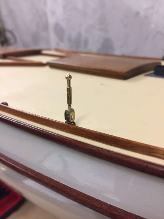
some progress: the shroud chain plates were finished & installed, & the mast base likewise.
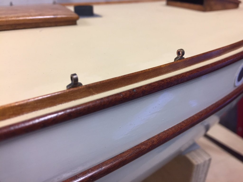
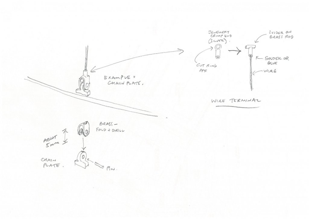
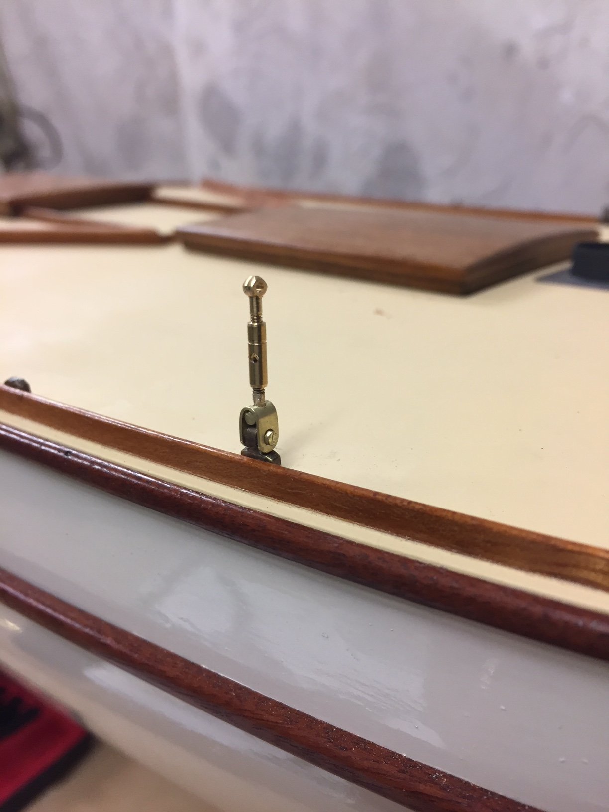
I was hoping to do a simple & well scaled way of terminating the shrouds at the chain plates. The initial idea was as per the sketch below, but it didn't include the turnbuckles.
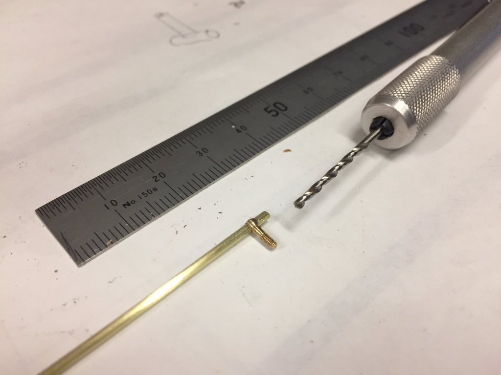
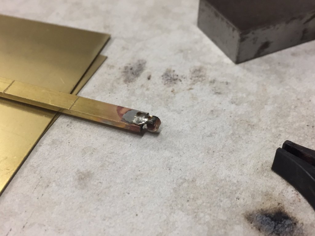
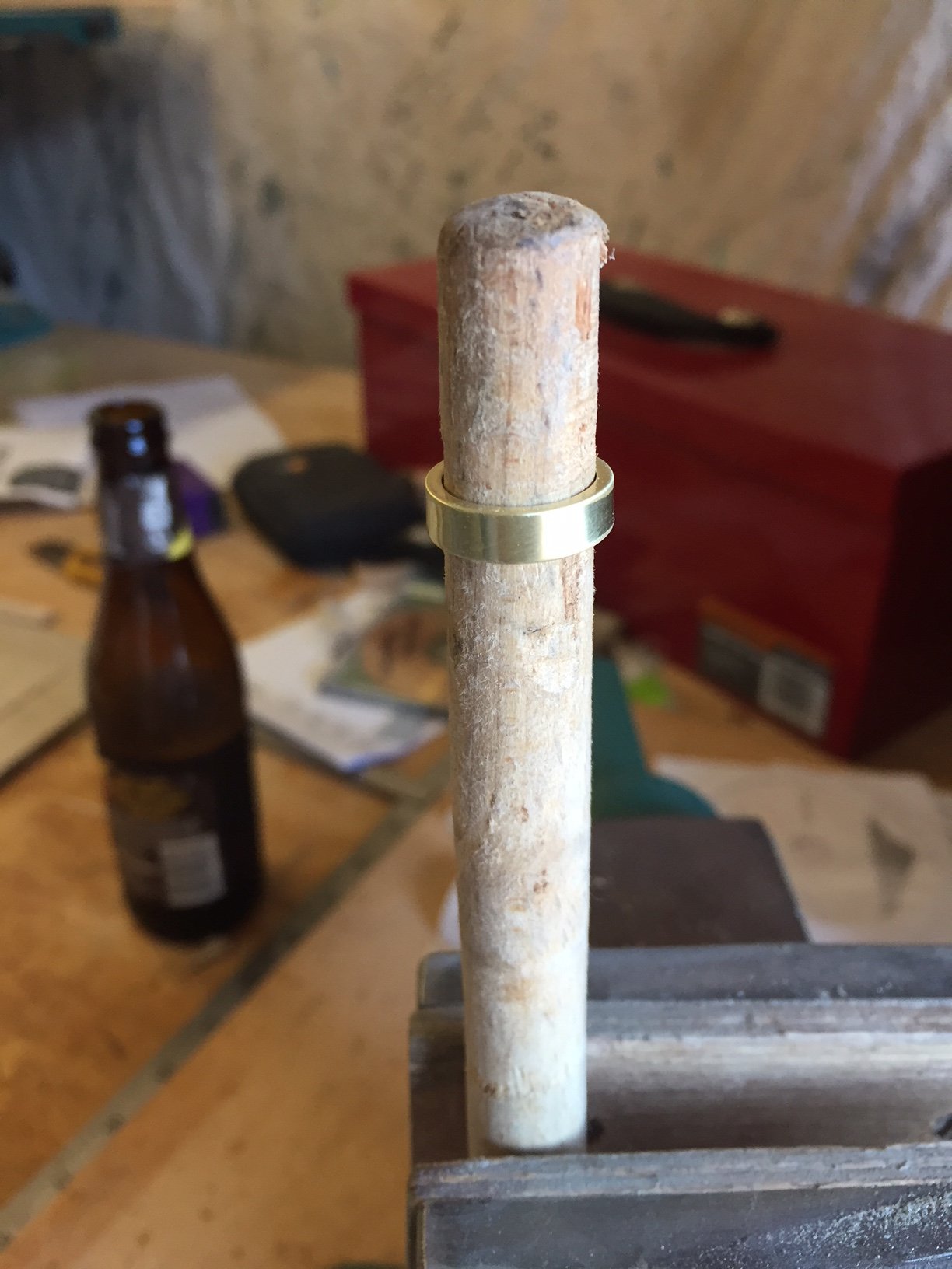
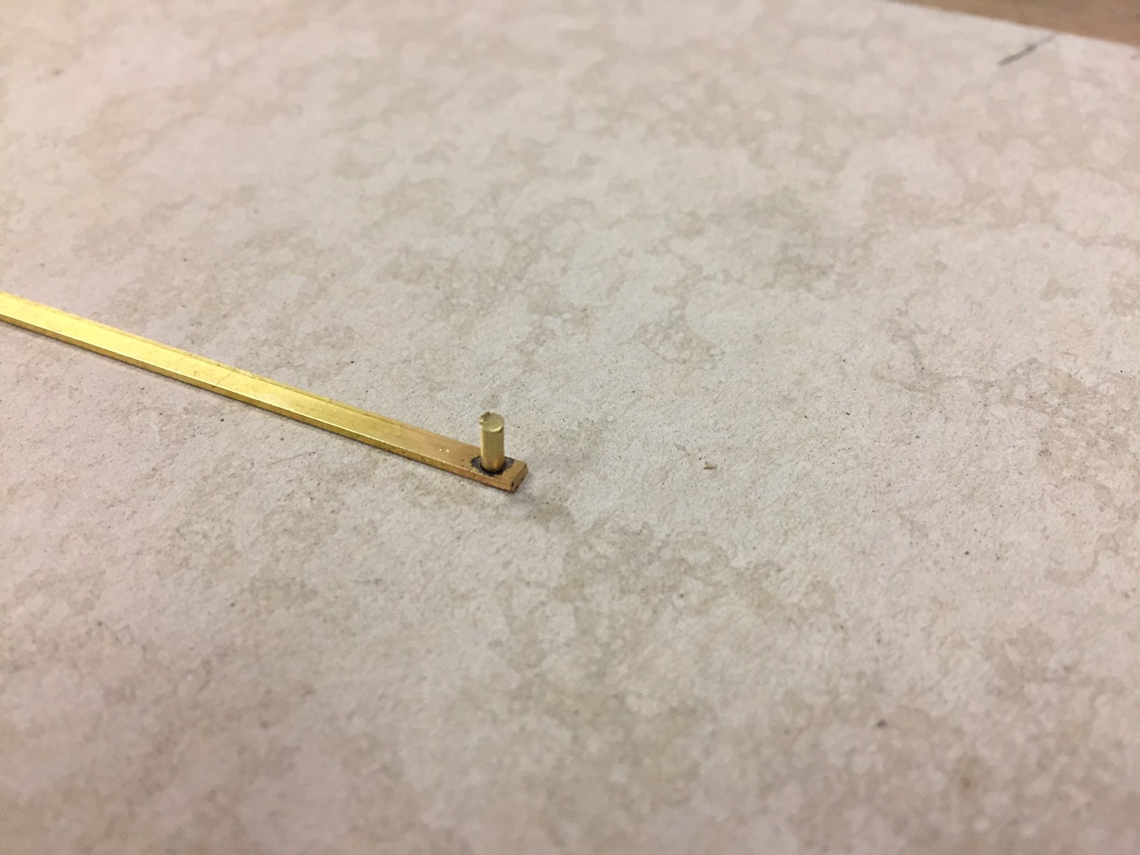
So I turned one end of the turnbuckle into the shaft of the T. Not quite finished, but it's a test run.
thanks, Mark
-
Hi Vaddoc
it sounds like the sanding sealer is the same thing as I meant. In your position I would consider doing the sealer & leaving the topcoat painting until you were sure that the movement had settled down. It's a big deal to do a final topcoat, & to wait a bit longer after doing the sealer coat might just mean the topcoat doesn't need to be redone. Best wishes for whatever you decide to do.
Mark
-
HI Vaddoc
she is looking good & will be a great model.
Have you thought about undercoat paint in collaboration with the filling? I would think that filled, sanded & undercoated the timber will be more stable.....having filled the gaps, you don't want the timber to go back fully to its original dimensions either. And a good undercoat will sand well, so that if you do need to resand where some filler might be pressing out a little, you can easily do that.
Mark
-
-
thank you for your advice & comments, this has helped a lot
Kurt, I'm guessing on around 8mm diameter actual size shrouds & stays, & that equates to about 0.03", & Beadalon has 0.76mm diameter which equates to about 9mm actual.
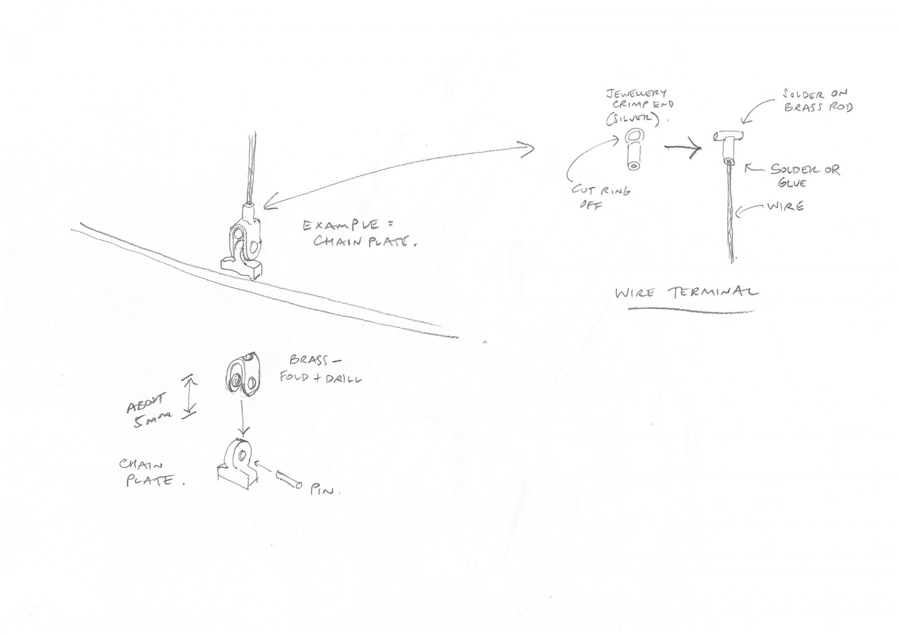
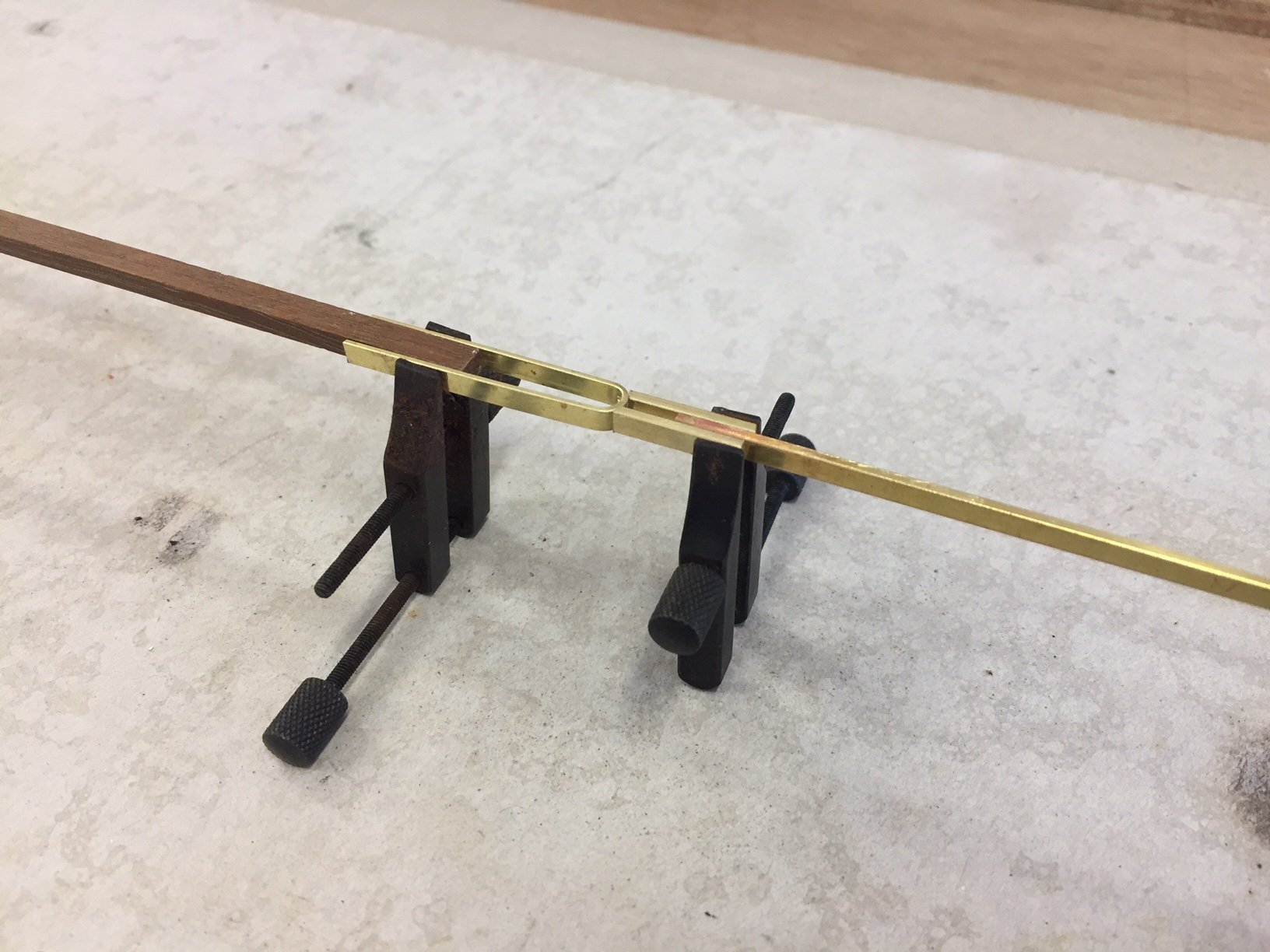
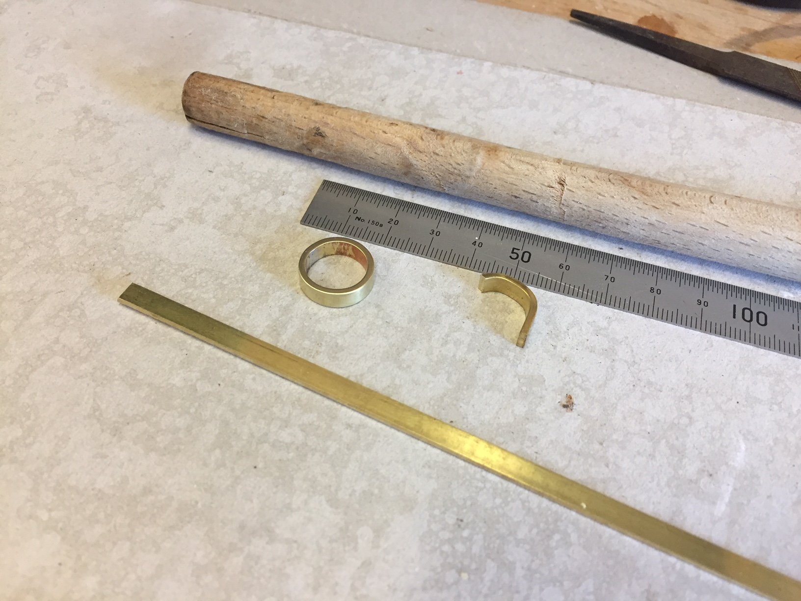
My thought is to do something like the details sketched out below: use a standard silver jewellery crimp end & remove the ring, then solder a piece of solid brass rod into to T shape, & solder or crimp the wire into the crimp end (or glue). This fits into a folded joiner that's pinned to the chain plate eyes - or whatever it's being joined to. An option is to use brass tube instead of the crimp end, & see if I can get it to solder or glue well enough.
see below, I think this will work.

-
-
-
thank you John, Art, that's great.
I'm just wondering if there's a way of having the crimps .... look less like crimps & more in scale. I have a picture in my head of them & perhaps they are more sophisticated than I imagine.
Do you ever solder it as a way to join or form an end? I'm wondering about soldering a small U shaped piece of brass to it, & then pin that U to a tang, plate, chain plate etc...
Mark
-
Hi all
I'm building a 1:12 yacht model, the actual boat would be 28 foot hull (around 9m) & a 20th century yacht - so the shrouds would be wire perhaps 8 to 10mm diameter actual (or 0.65 to 0.8 or 1mm diameter to scale). The actual rigging would be stainless steel, so it would be nice for it to look like that.
It needs to be straight when tensioned a bit, it won't look any good with kinks. Also, I think that some texture is preferable, to replicate the texture of the SS wire, but I'm open to solid...
I'm be grateful for any suggestions, thanks
Mark
-
Hi
very lovely model & wonderful boats.
A question: in an early photo the hull is massed up with bulkheads & solid blocking - is this the hull that you painted or did you line it off with thin surface planks?
You said early on in the posts that there are none in existence? Perhaps there are no original ones left, but a friend from Sydney was involved this year in taking several historic 18 Sydney footers over to USA to race against some sandbaggers. See some information & photos here of the event, (& I am guessing that off centre harbour will do a video on it):
https://www.sydneyflyingsquadron.com.au/8-footers-taking-on-the-usa/
https://www.facebook.com/AussieOpenBoat/photos/pcb.1698530063513134/1698525546846919/?type=3
https://smallboatsmonthly.com/2017/09/sydney-flying-squadron-visit-annapolis-md/
It is interesting that there were 22' & 24' skiffs here & from what you can see in the old photos they were really quite similar lines to your lovely model.
all the best, very nice,
Mark
-
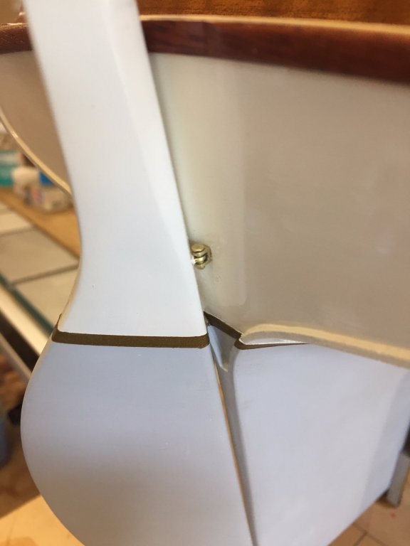
thanks Carl, perhaps I'm one of the people (including drunks) that the gods protect from their own ignorance...I had no idea it might be tricky. I heated the plate from underneath & soldered from above.
Hi John, appreciate you thoughts on that, I'll work something out to pin them. A small patch in the paint will be straightforward to repair.
-
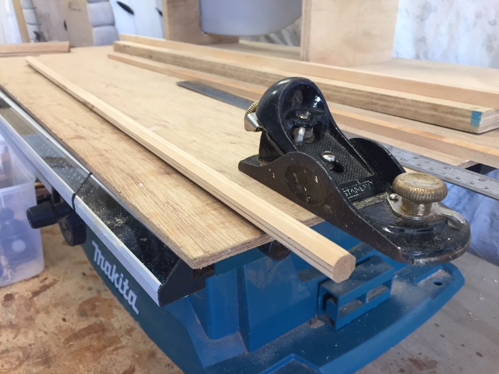
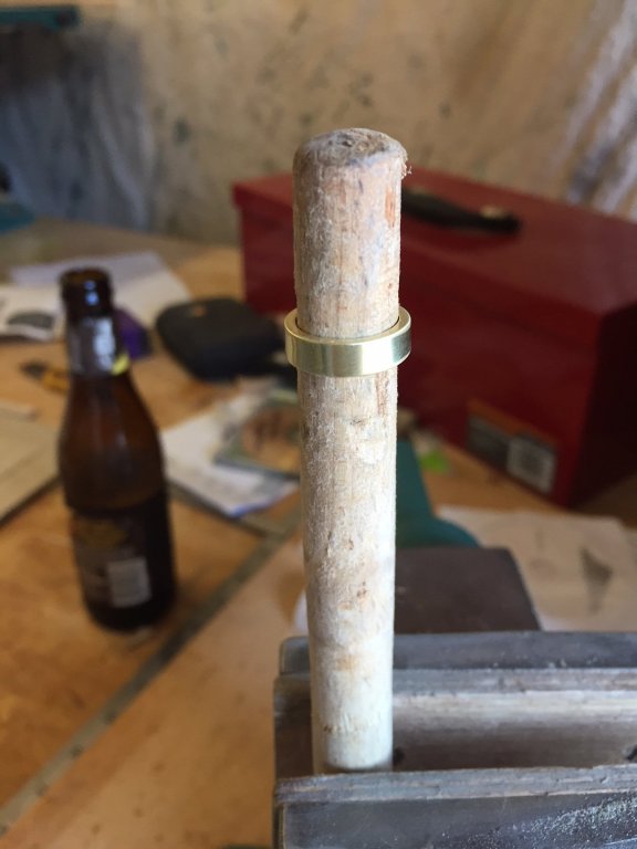
I've shaped the mast, it's been sanded since this photo & one thin coat of varnish applied with a cloth & rubbed until satin finish. The timber is plantation Kauri Pine, lovely fine grain without pores & a good colour for this model. One interesting thing to note is that I bought some 12mm diameter dowel & it looked too thin, even though it was only a small amount under sized. So I made this one at 12.5 - 13mm diameter & it looks right.
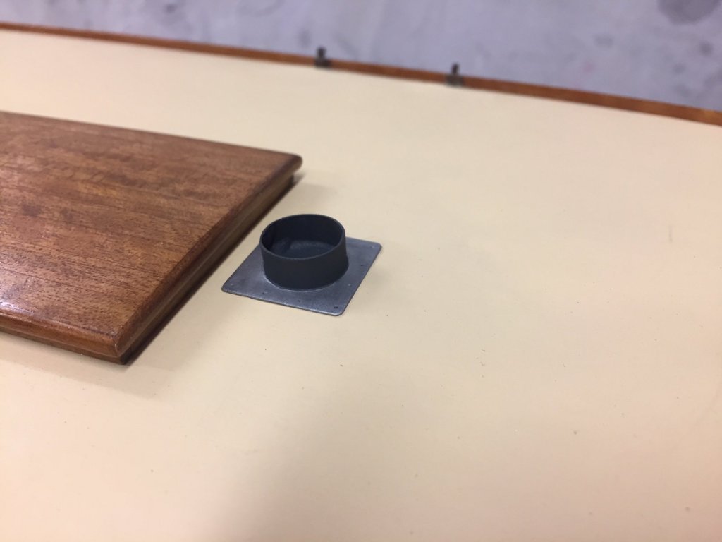
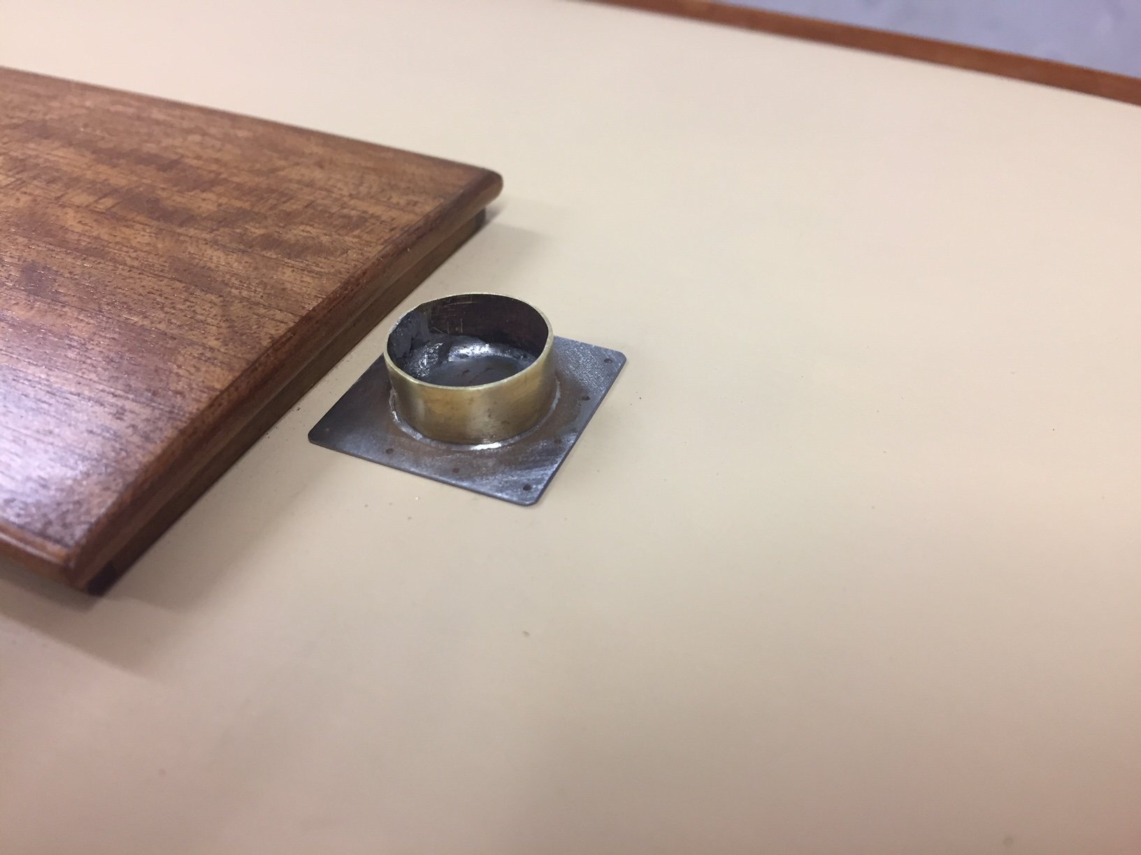
The mast step is to replicate the kind of fitting mostly used, at least here anyway - which is a roofing fitting called Dektite - designed to shed water on a metal roof around a circular flue. The idea is the brass gets painted dark grey (a rubber boot) & the plate is left silver (aluminium & rubber base).
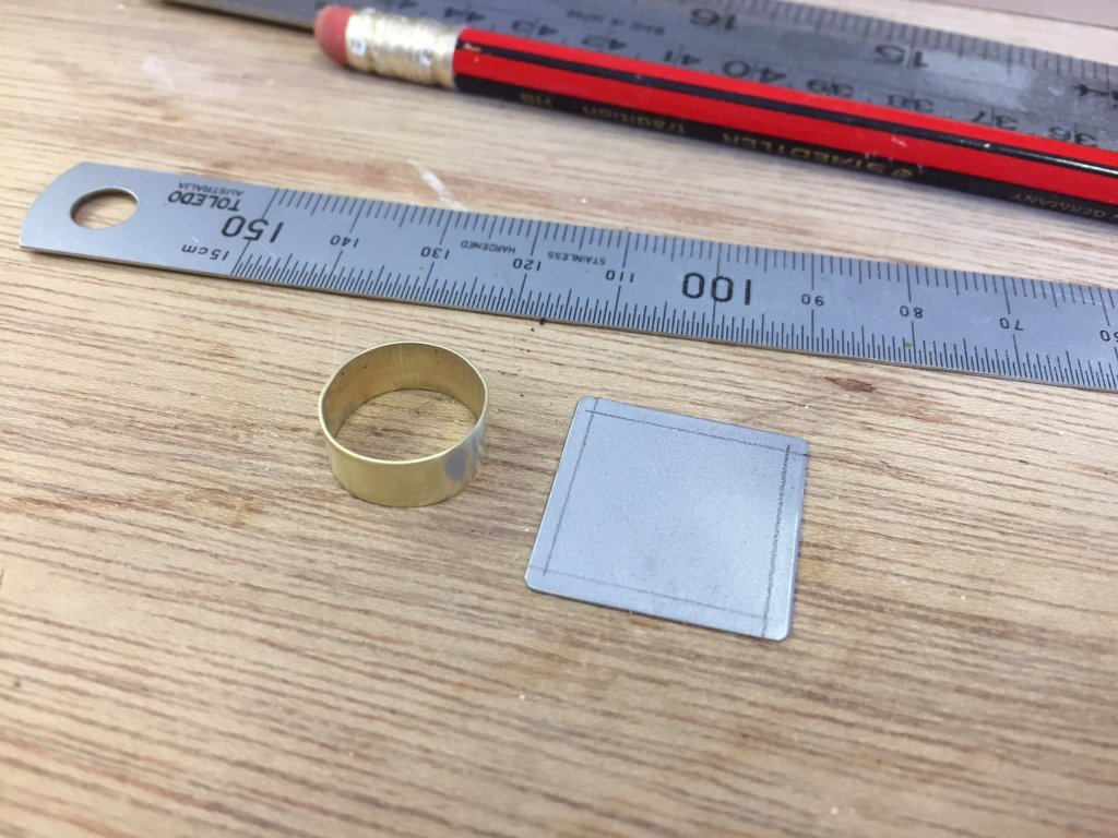
Bad news was that I didn't realise the metal was steel rather than stainless steel, the colour threw me because it has a sandblasted finish. It rusted a bit overnight, so I sanded it & put a coat of varnish on it. If that doesn't work then I'll just paint it grey.

The chainplates for the mast shrouds are underway. I didn't plan the installation when building the hull, except to put a kind of sheer clamp in below the deck. I'll glue the chainplates in with epoxy, I think that will work.
-
thanks all, the positive character of this forum is very helpful in so many ways.
Hi Keith, that's right I don't have many tools but it seems to be enough. Some years ago I built a sailing boat, & when starting wasn't sure what tools I would need so decided to only buy them when I couldn't do the job another way using an existing tool - & I've kept using that philosophy notwithstanding the pangs of looking through catalogues of delicious tools. I can understand the allure of beautiful machinery & learning how to get it purring - plus the amazing results that tools & knowledge together can bring - but this is my way I suppose. I couldn't do without the 10x vision headset.
all the best, Mark
- Omega1234, John Allen, KeithAug and 1 other
-
 4
4
-
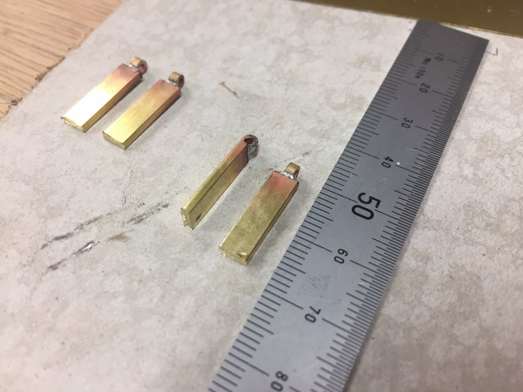
The spreaders are pretty much finished now, the arms are from 3mm brass tube flatten each end with soldered in the squashed end as a filler. Polished & shiny, but I'll likely dull them off to a brownish colour.

from forwards, sitting on the stock that will be the mast
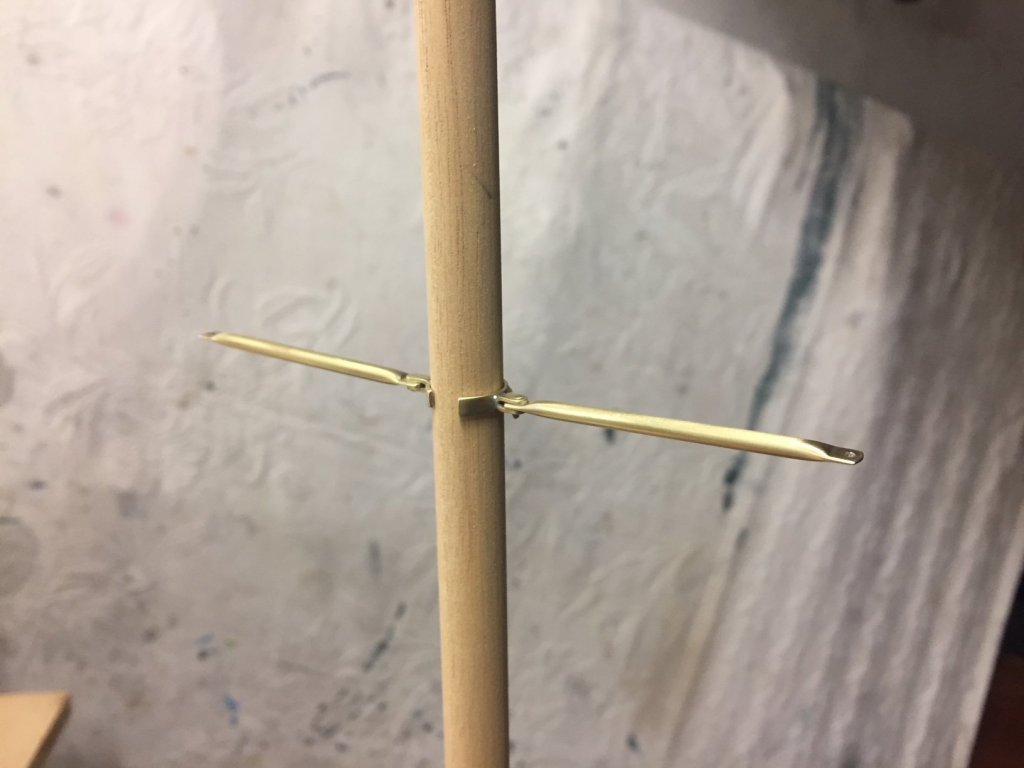
from aft side, the lower shrouds fixing tangs visible

thanks all
- Farbror Fartyg, Omega1234, cog and 5 others
-
8
-
Hi Michael,
to be honest, I thought I was silver soldering, but that's a more reliable indication of how little I know than anything else... The product I'm using proudly calls itself 'silver bearing solder' on the packet, but the company's webpage for the product doesn't seem to use the word silver http://www.harrisproductsgroup.com/en/Products/Alloys/Soldering/Lead-Free-Solders/Stay-Brite-Kit.aspx
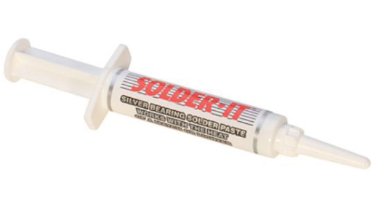
You're certainly correct that I can sand the solder afterwards & remove the excess quite easily with sandpaper & files, & am using a Dremel VersaTip butane torch. I also bought some silver bearing solder paste (image below of the product), I have been able to melt it but it's more difficult to get it to flow than the Harris product & I've not experimented enough with it.
It would be good to know for certain, to clear it up both for myself & for the benefit of others.
Mark
-
thank you everyone,
Gary I'm new to brazing but I had done some work with brass before. I reckon brass is more similar to working with timber than anything else, it's a pretty soft material to work - it drills, files, sands, polishes all quite easily. The number one thing I've learned is that you don't have to be the world's best brazer, good cleaning up can turn a sow's ear into something surprising - have a supply of small files & sandpaper glued to sticks & try & get some really fine paper, even 2000 grit or finer. Holding the parts when brazing is difficult too.
But, this forum has a lot of information & a lot of people very generous with their knowledge & skills.
all the best, Mark
-
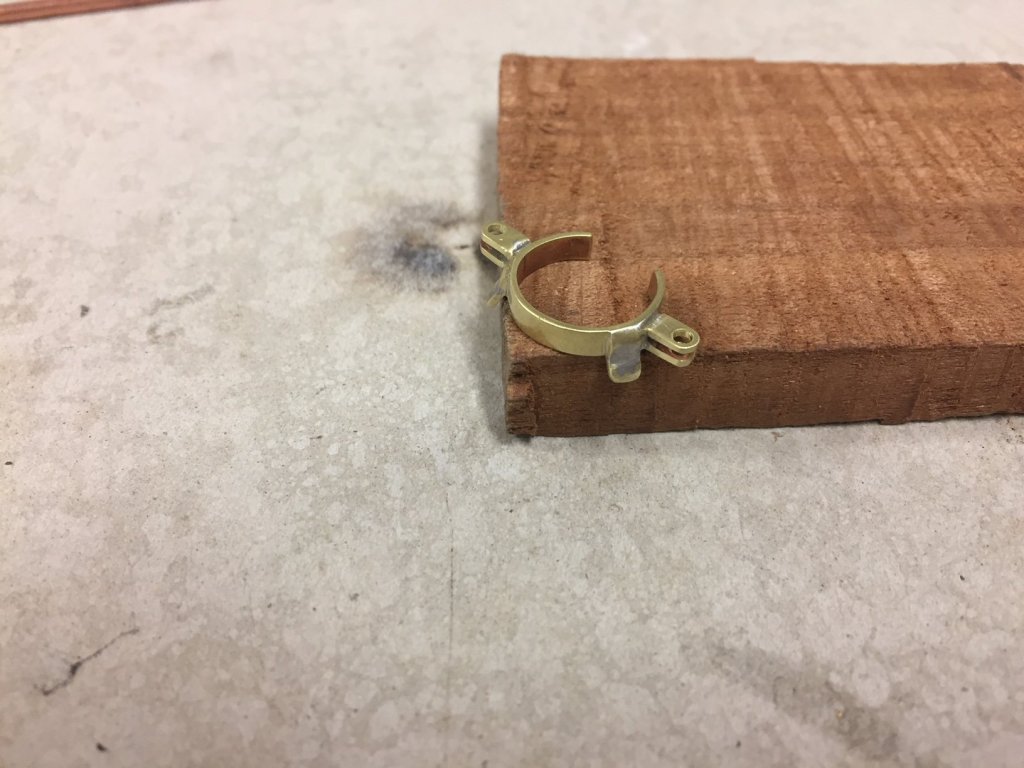
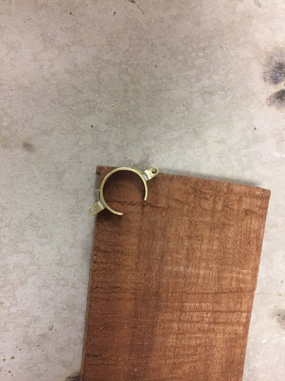
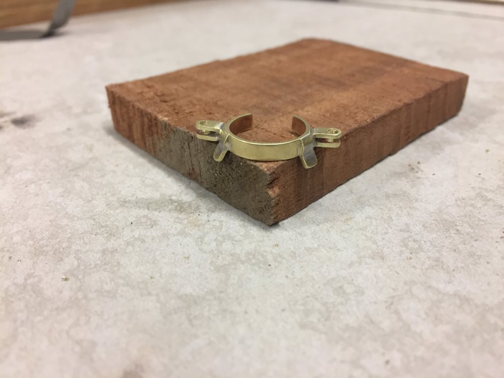
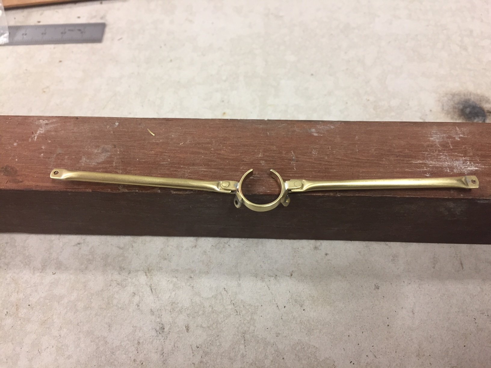
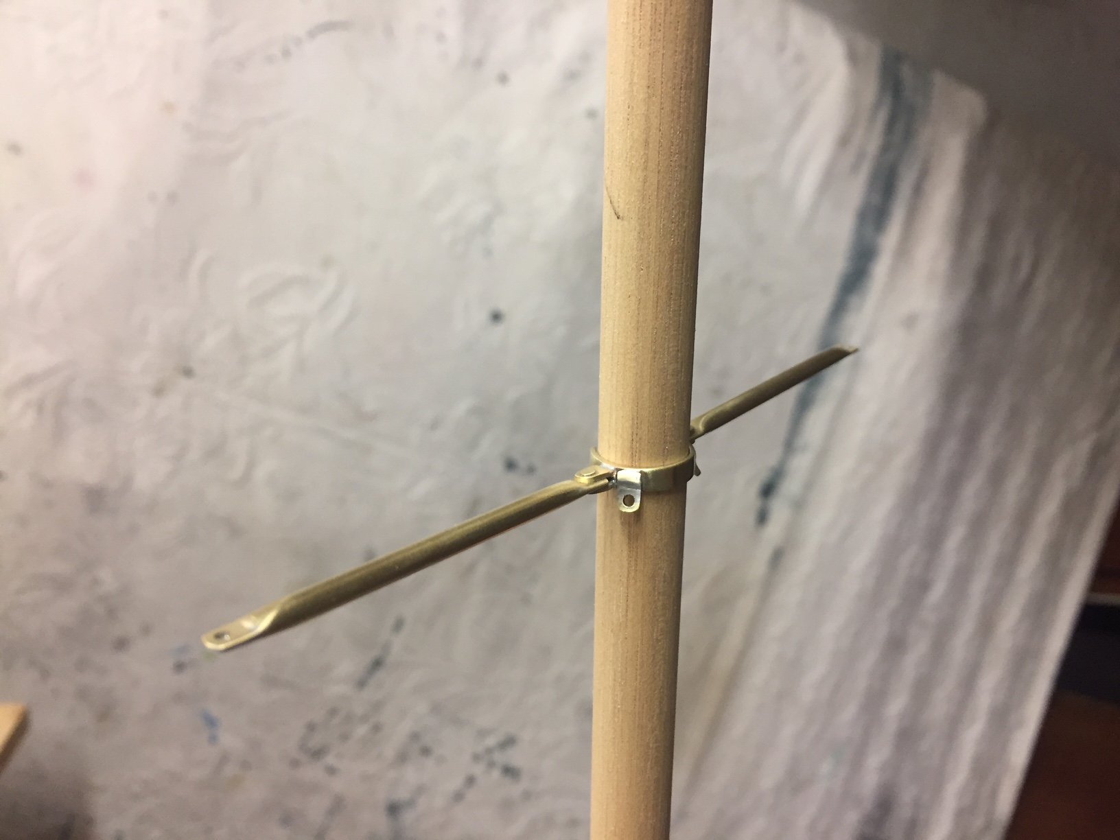
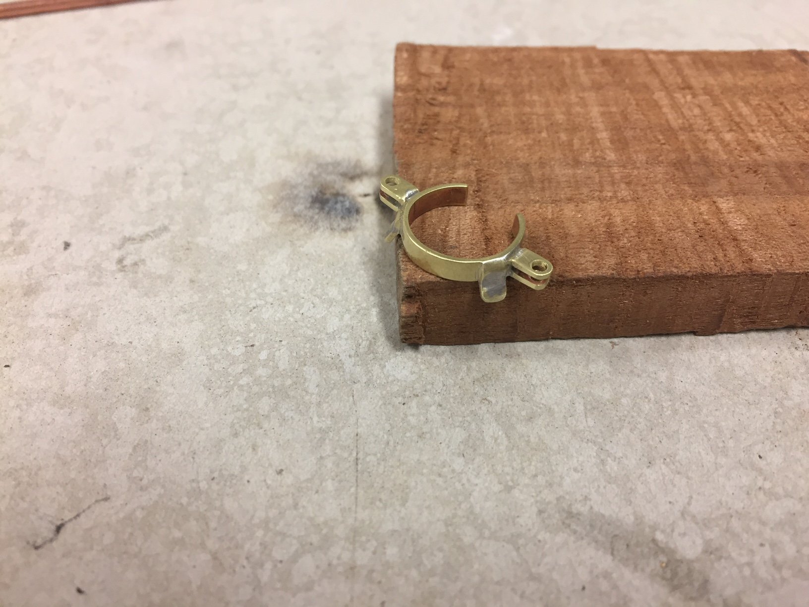
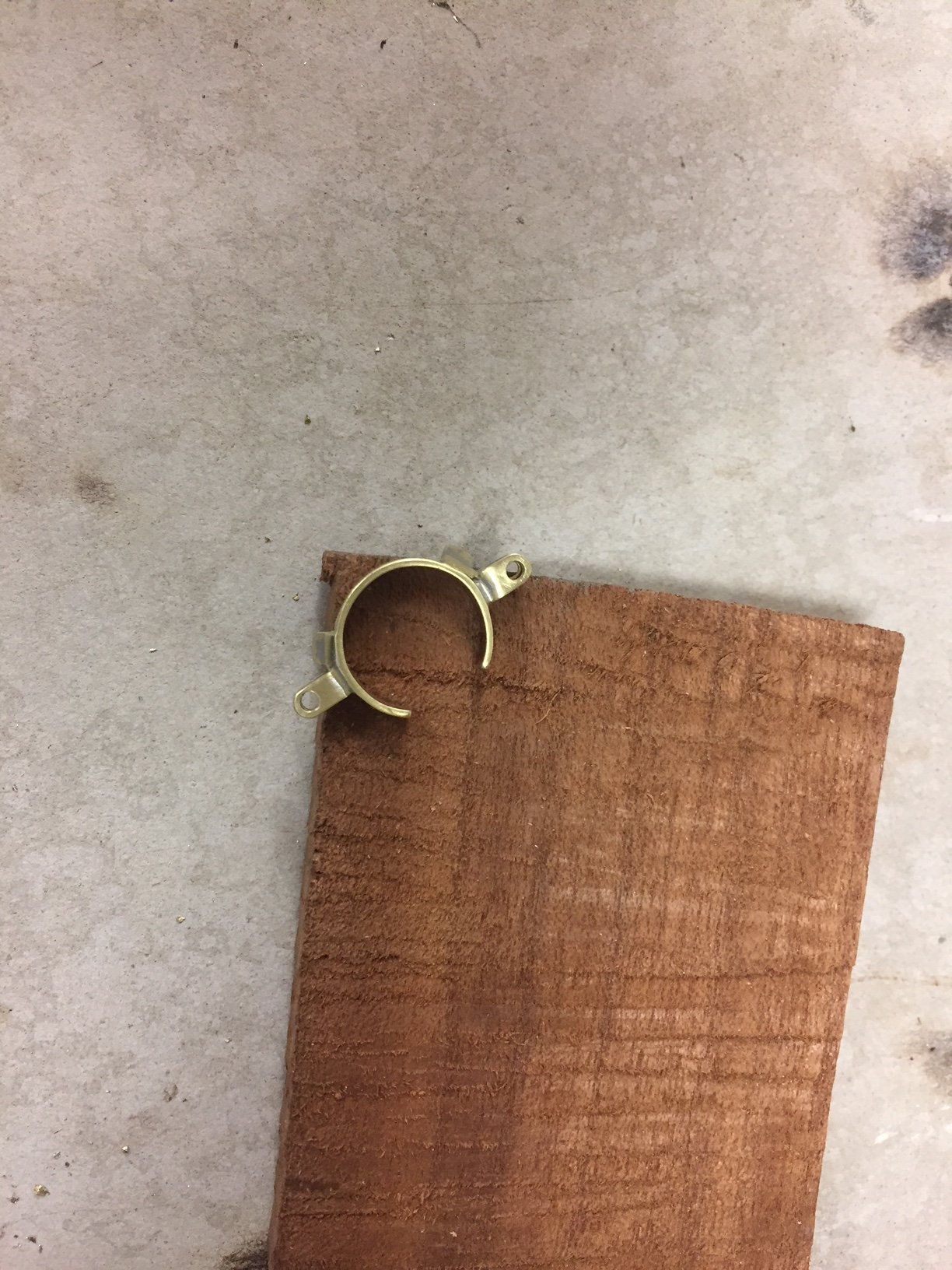
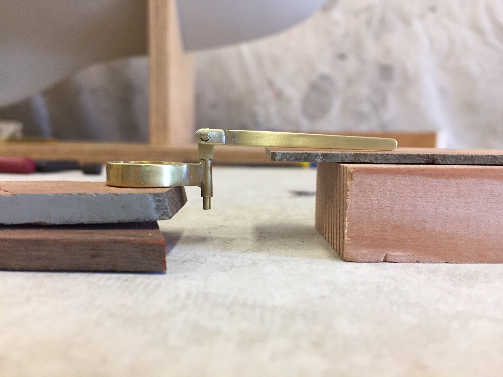
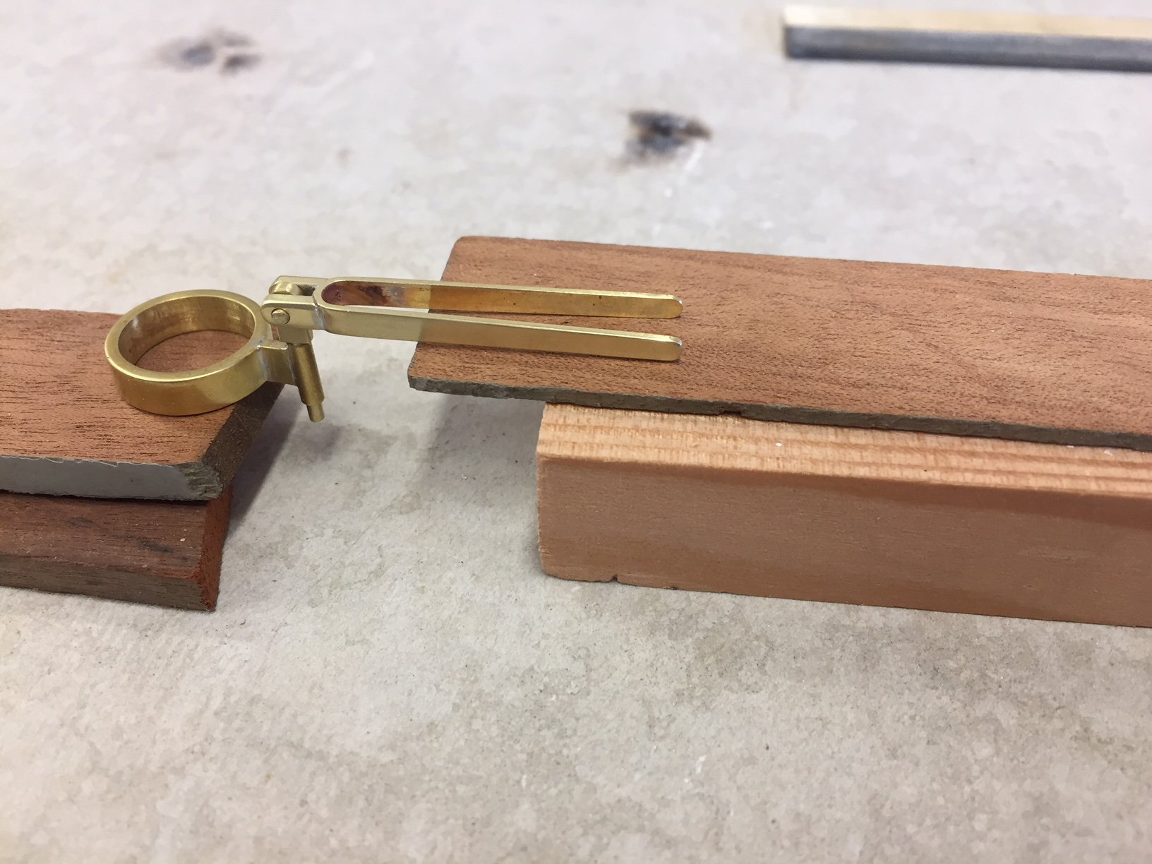
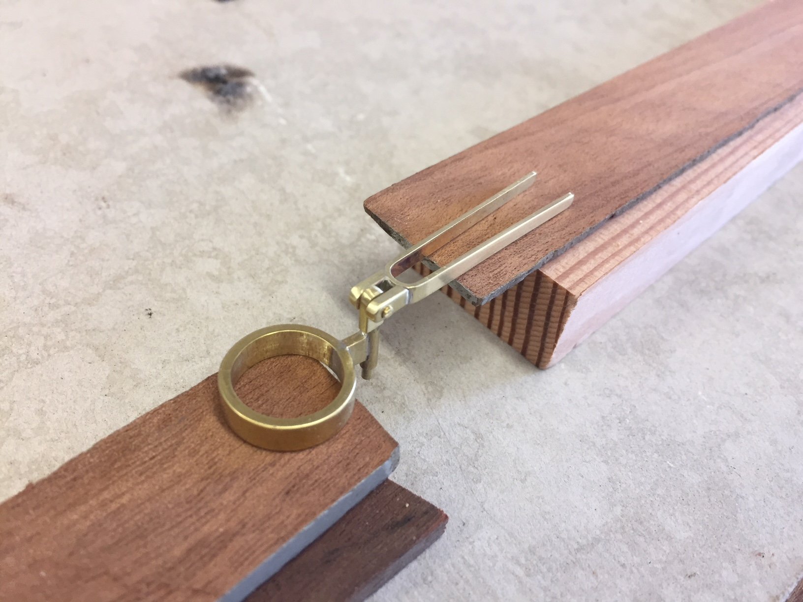
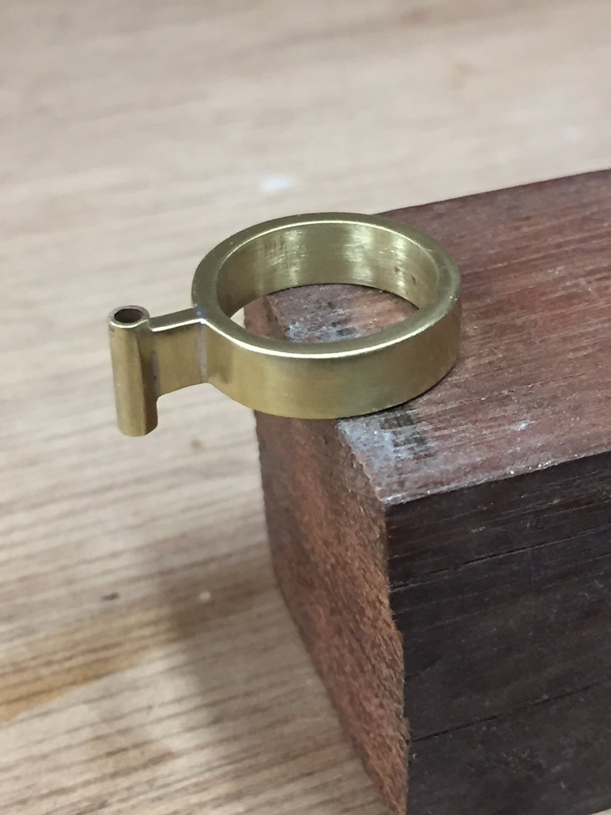
I've made the mast base for the spreaders, the mast ring is open at the forward side - just looking at it now I may widen that a little. The horizontal double flanges are for the spreaders & the tangs behind them are for the lower shrouds. I'll drill the tangs when I've worked out the detail for the shroud ends. The spreaders could be in brass tube with flattened ends, or maybe timber. Timber spreaders would look pretty but I'm not sure that I want to draw attention to them....
- John Allen, KeithAug, Jack12477 and 9 others
-
12
-
-
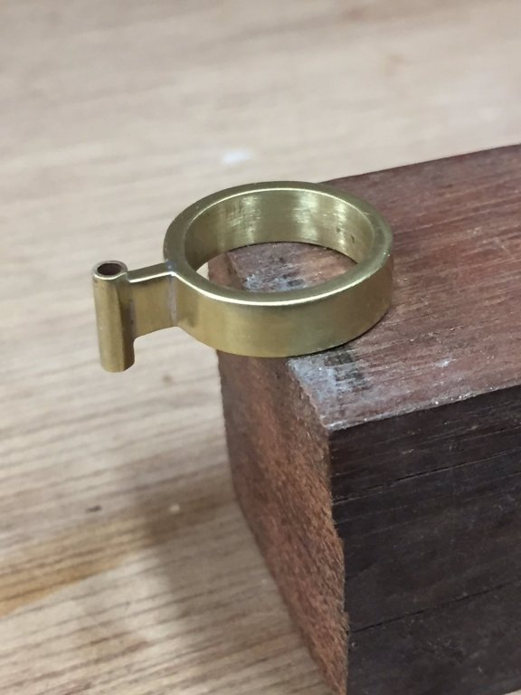
I made the boom end fitting of the gooseneck, it will need some small lateral holes for the boom fixings. The process I used was:
some flat bar was bent around a shape of a suitable width
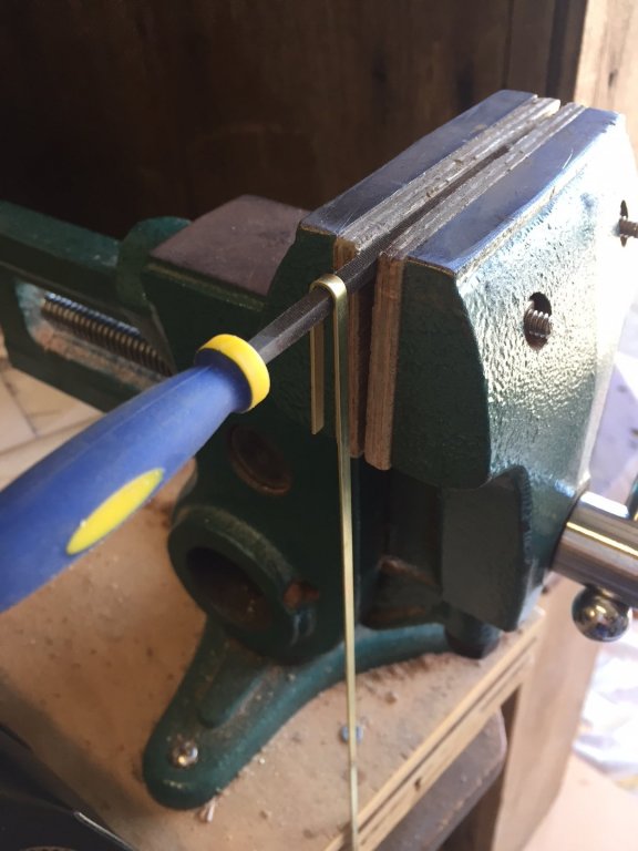
some other pieces cut, ends shaped & held for brazing

finished


- kees de mol, oneslim, cog and 8 others
-
11
-
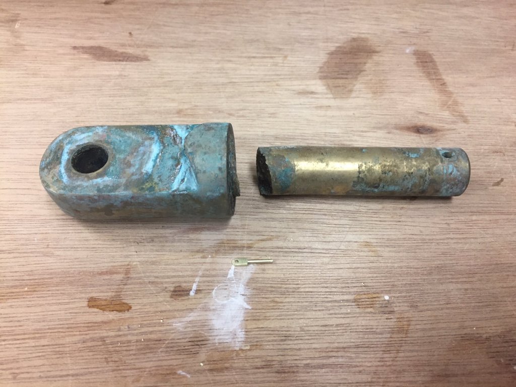
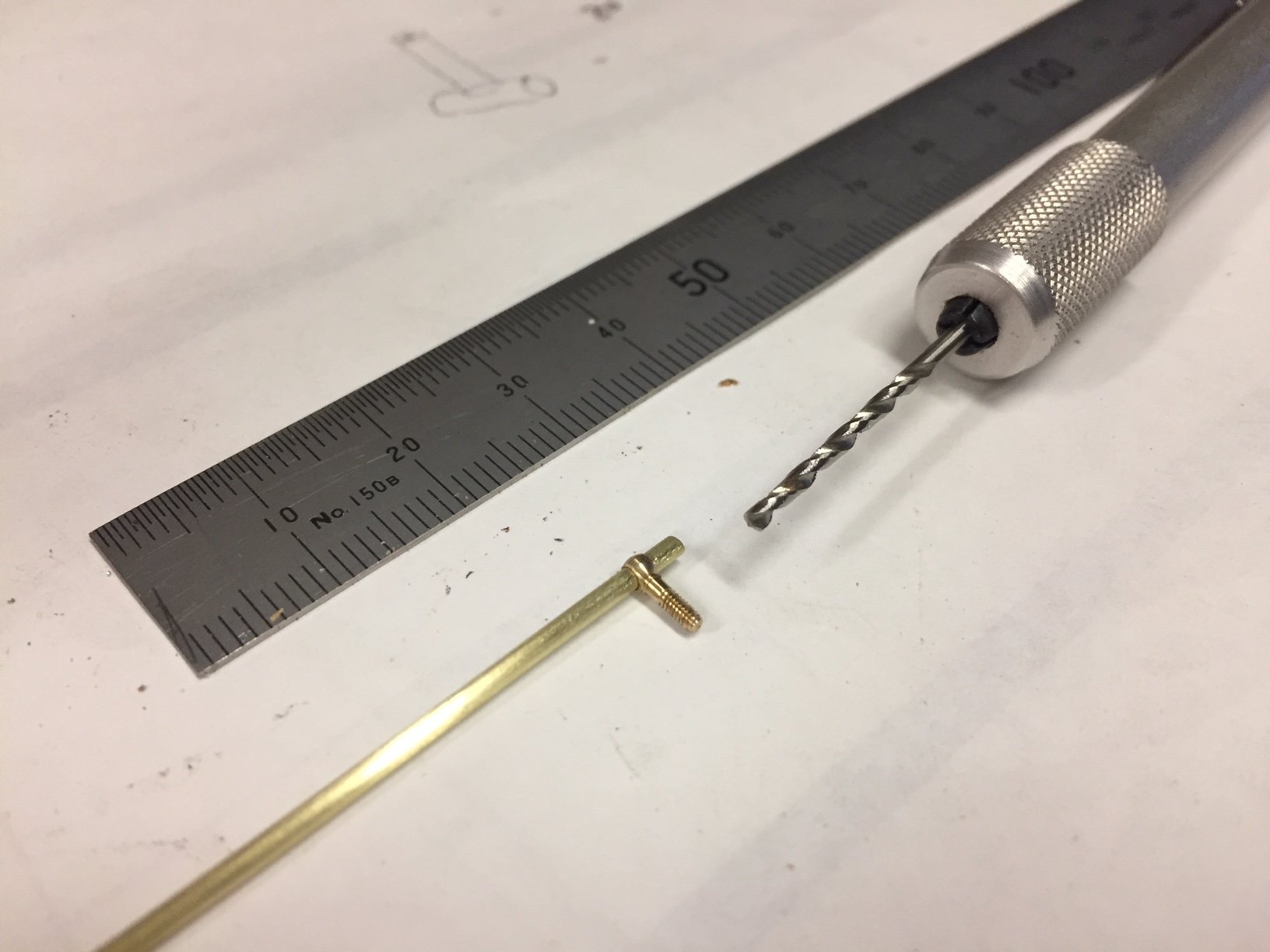
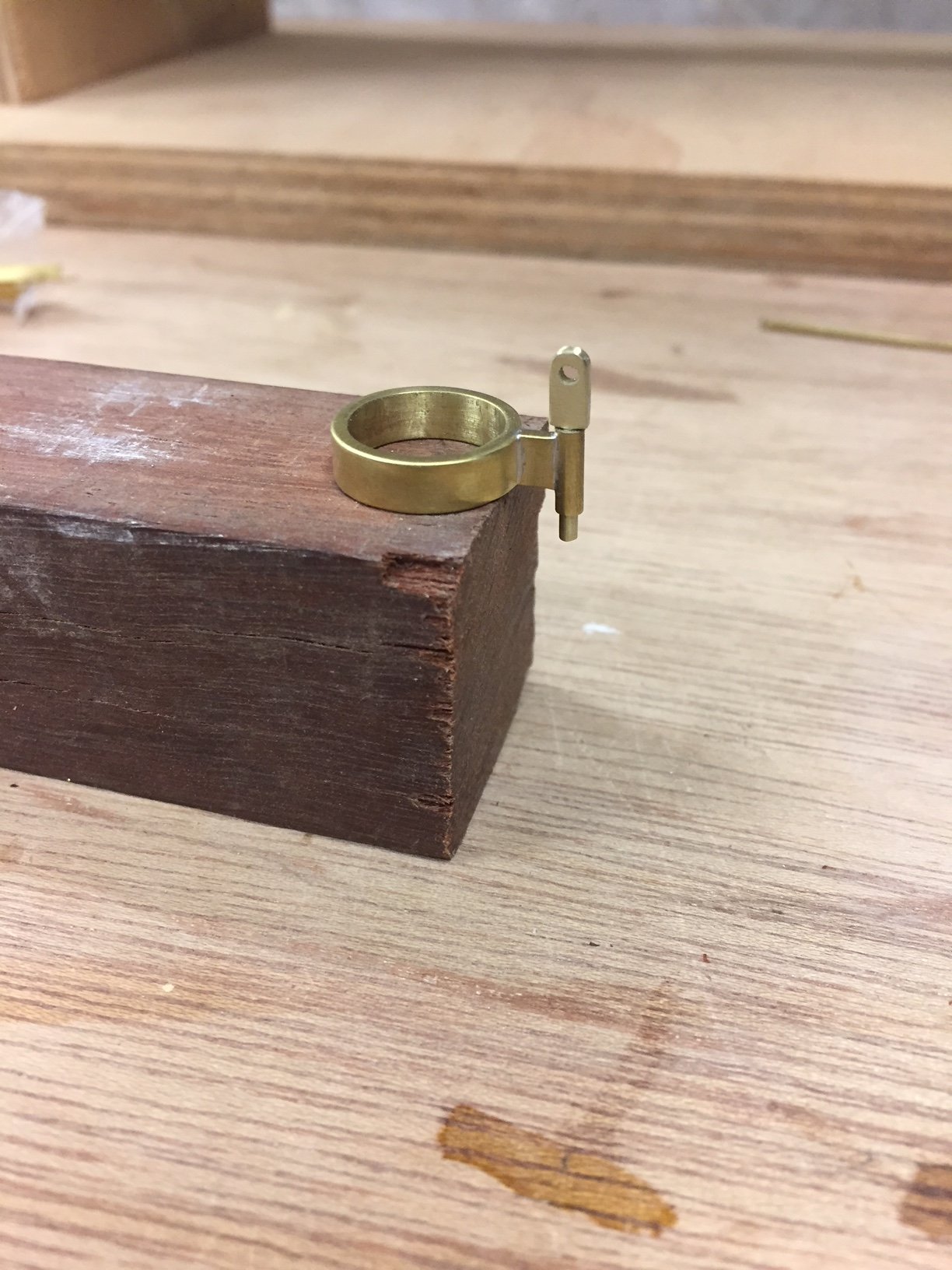
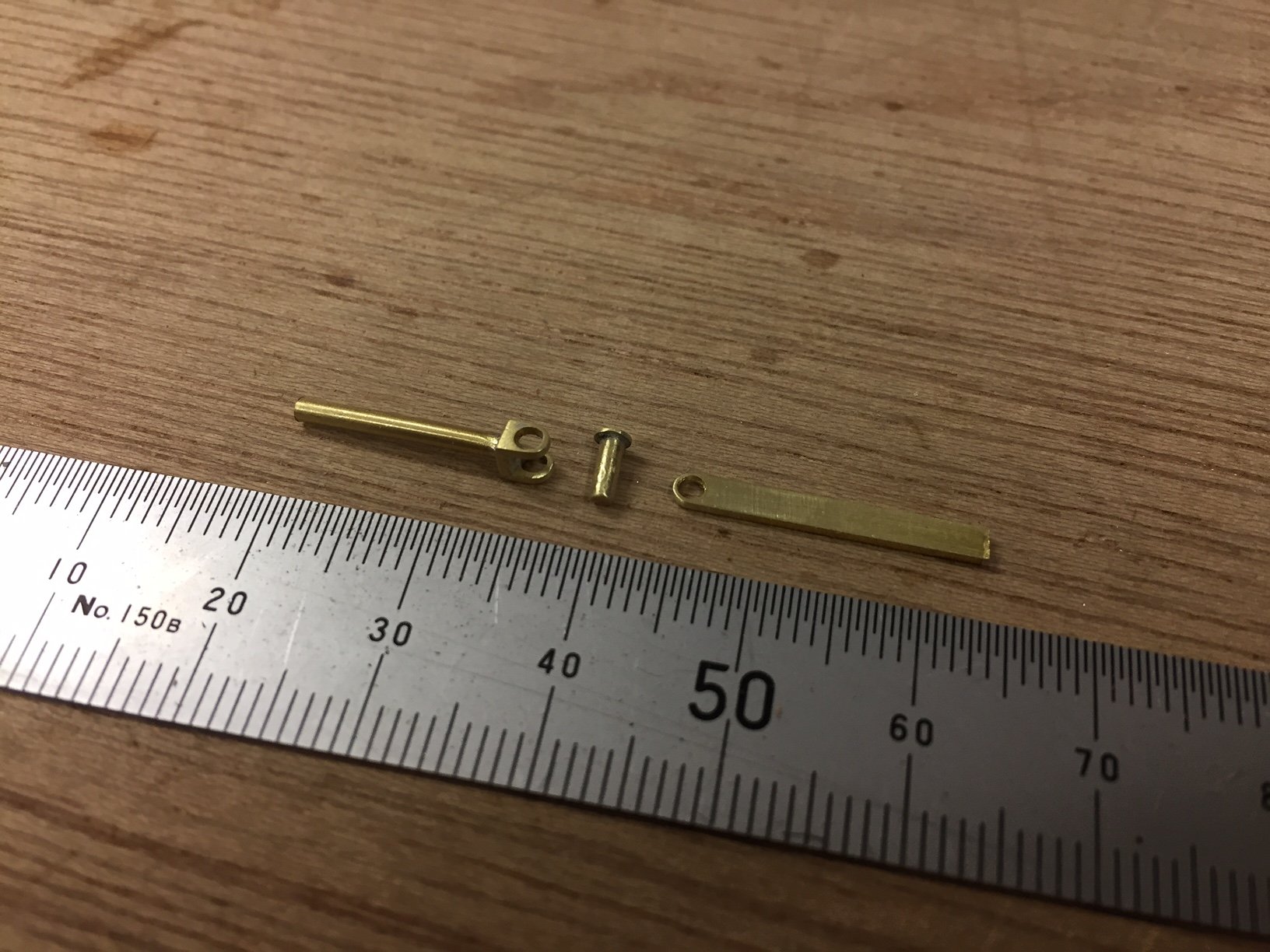
A small update, but an interesting one for me. The gooseneck pin:

The 1:12 pin shown alongside a real gooseneck pin. What's striking is the difference seems much more than 12x; & then it dawned on me that 1:12 is really just one way of defining it. The linear scale is 1:12, but the volumetric scale is 1:1,728; when you see the pins together you see the volumetric scale rather than the linear scale. It's a dramatic picture anyway.
-
thanks all
Hi Carl, yes I do use silver solder. The process is new to me, but after some research - including asking advice in these forums - I got a small butane torch plus silver solder. Is your question related to getting the solder into a more difficult joint, like the tube to flange above? You can see that my efforts to get it into the joint gave me an excess on the other joint. What ended up working was having the torch flame from one side & touching the joint with the wire from the other side. However, I'm interested if you think that silver solder paste will make it more accurate.
Hi Bedford, it was more the angle that gave trouble - & of course my inexperience. I'd put the piece of solder wire towards the joint & when it went into the flame it melted & didn't get there. Only when I'd heated from one side & added the solder from the other did it work, & easily too. Lesson learned.
Hi John, Keith, thanks & best wishes
-
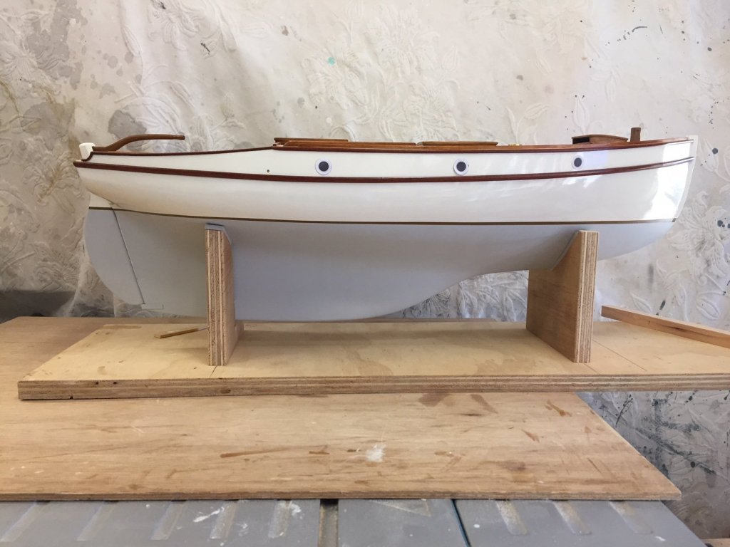
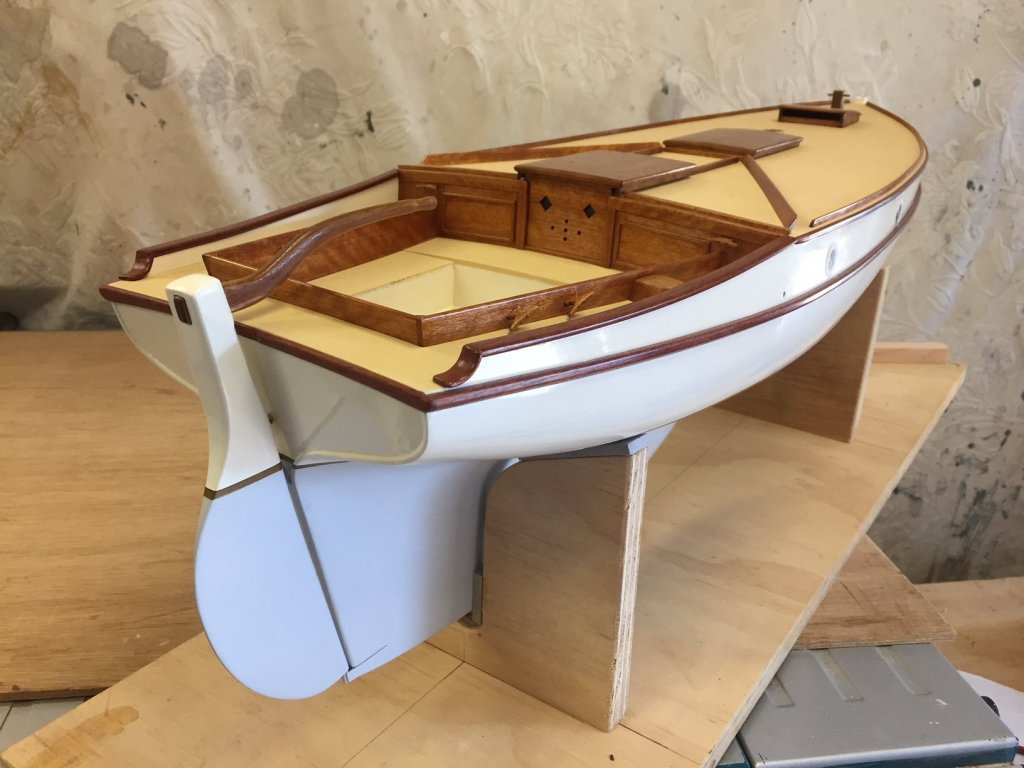
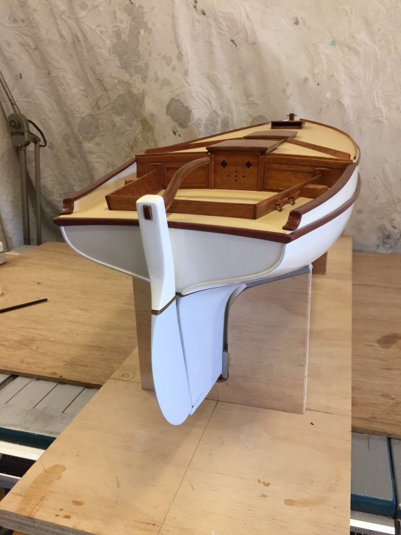
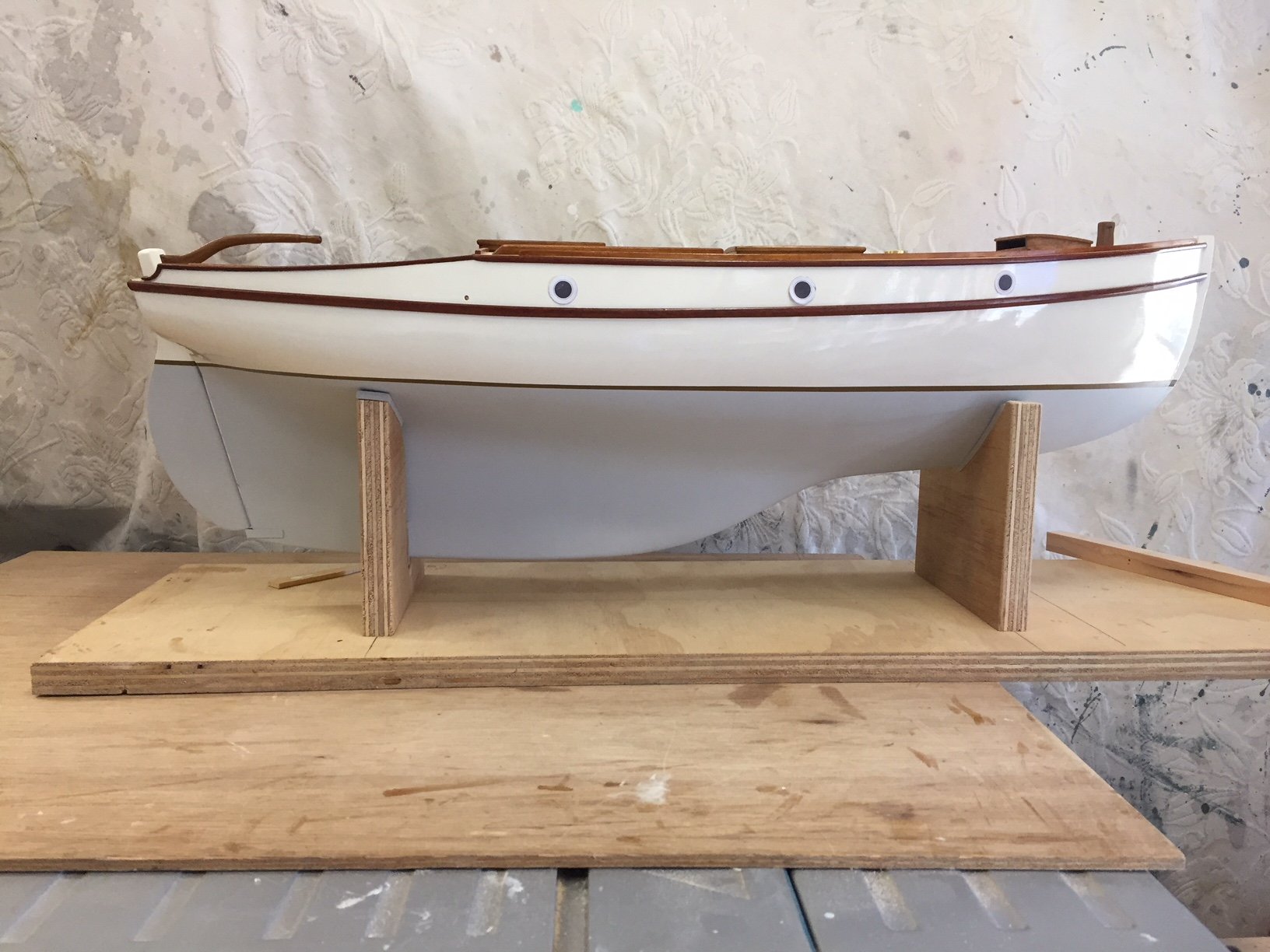
the rudder gudgeon & pintle are now fitted & the rudder is painted, the fitting looks to be in scale
The rudder curves are nice, unfortunately a phone camera lens seems to distort the shape of the hull - but you get the idea
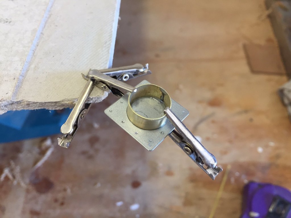
The next metalwork part is the boom gooseneck. I bent a piece of brass flat bar (about 1.25mm x 4mm) around some wood of the right diameter, cut & brazed it. This is the band that will go around the mast. You can see that it's not exactly round, but I don't think that will show when you can't see the hole, when it's on the mast.

like this
Flange, grooved one side to help hold the next part, the tube
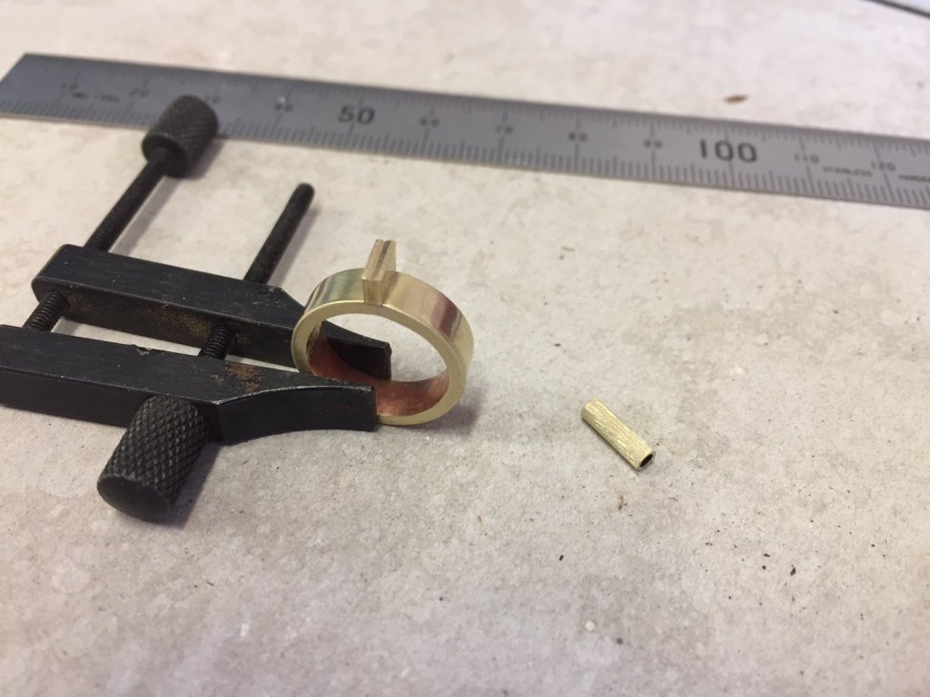
weighted to hold it during brazing, the tube didn't initially want to take the solder...

& the result: the next part is the pin, then the part that fits on to the forward end of the boom
until next time,
MP
- IgorSky, popeye the sailor, G.L. and 13 others
-
16
-
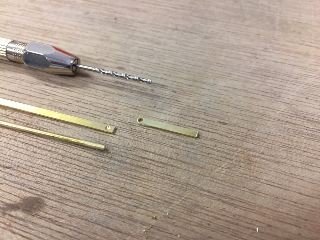
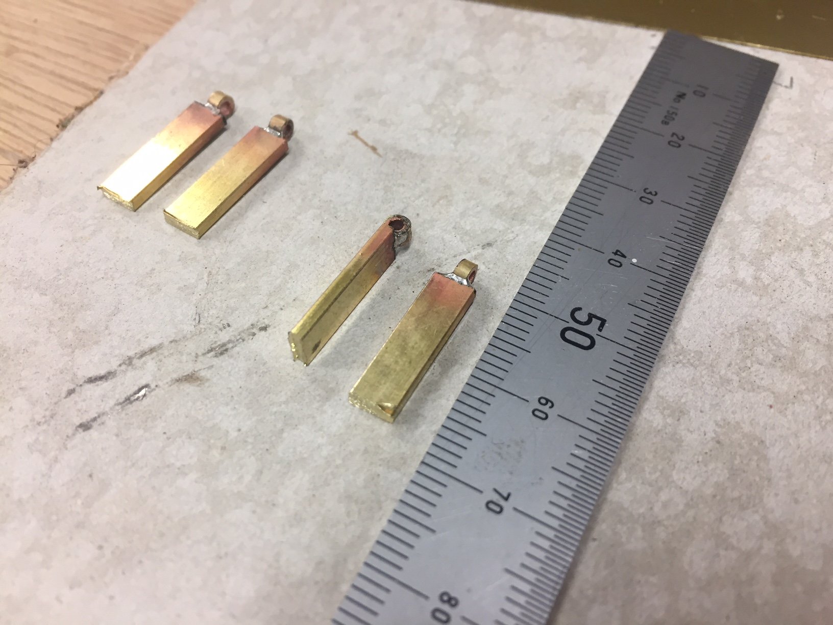
The gudgeon & pintle are now done, the first metalwork component is made & it feels good. I made the pin by brazing a cap onto a piece of rod. I predrilled into some flat bar to make it easier to braze them together.
The single drilled tab that will go into the rudder blade, plus the pieces for the pin.
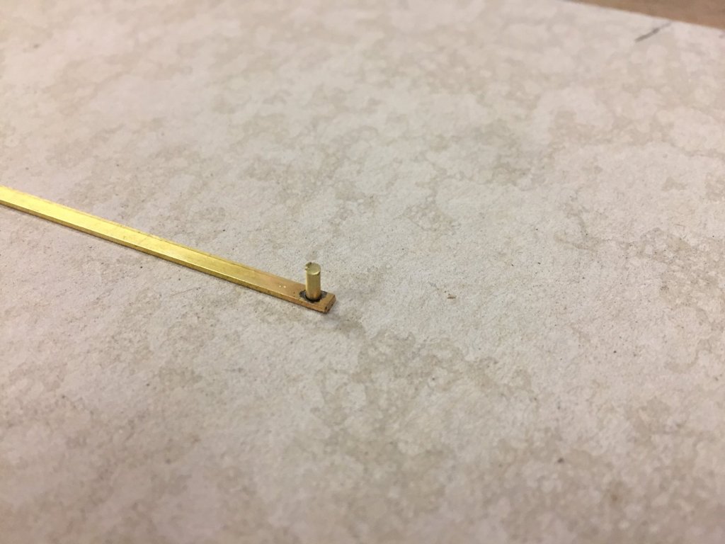
Partly brazed, but it needed a bit more solder.
The pieces. I sanded the flat bar round & also thinner to keep it in proportion.
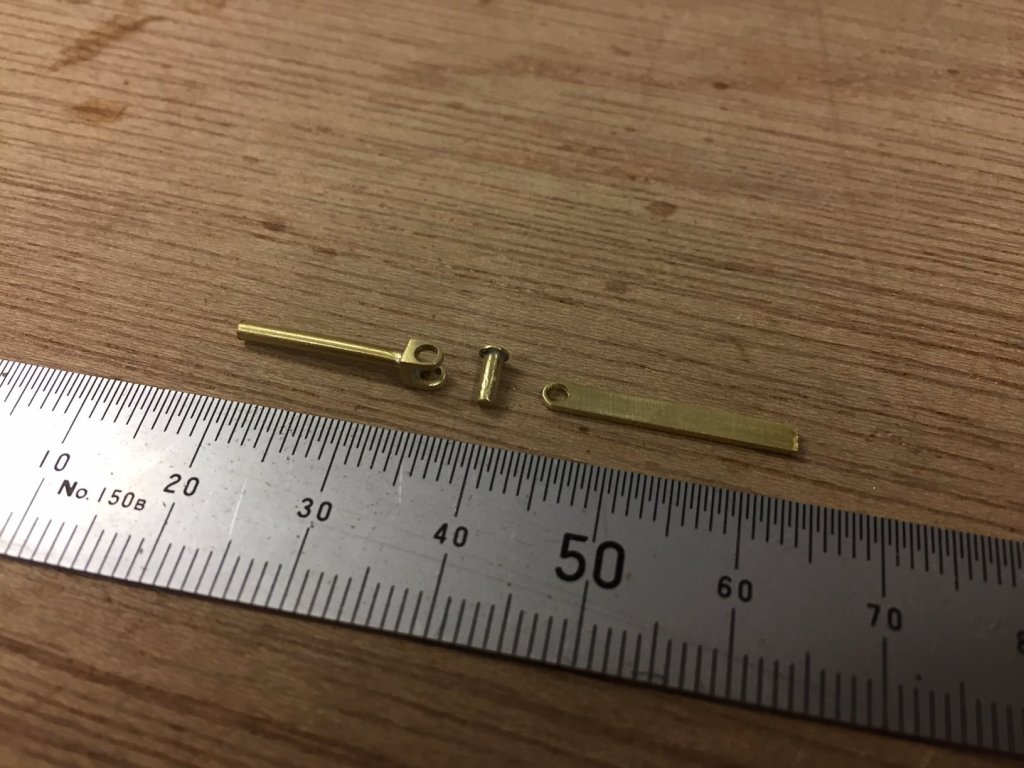
Done.


Deben 5-tonner by vaddoc - FINISHED - Scale 1:10 - a Whisstock yard design
in - Build logs for subjects built 1901 - Present Day
Posted
looking great Vad