
DONATION DRIVE - SUPPORT MSW - DO YOUR PART TO KEEP THIS GREAT FORUM GOING! (91 donations so far out of 49,000 members - C'mon guys!)
×
.JPG.ca33079f5815b861e67b9c2cccd37982.JPG)

Blue Ensign
-
Posts
4,566 -
Joined
-
Last visited
Content Type
Profiles
Forums
Gallery
Events
Everything posted by Blue Ensign
-
 An excellent and tricky conversion at 1:150 scale, she looks good.👍 Converting and detailing this kit to more properly represent a Seventy-four of the period (French in my case), proved the most difficult build I've done. Well done in both your perseverance and end result. B.E.
 -
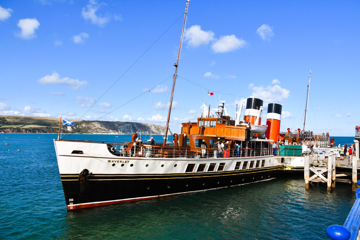
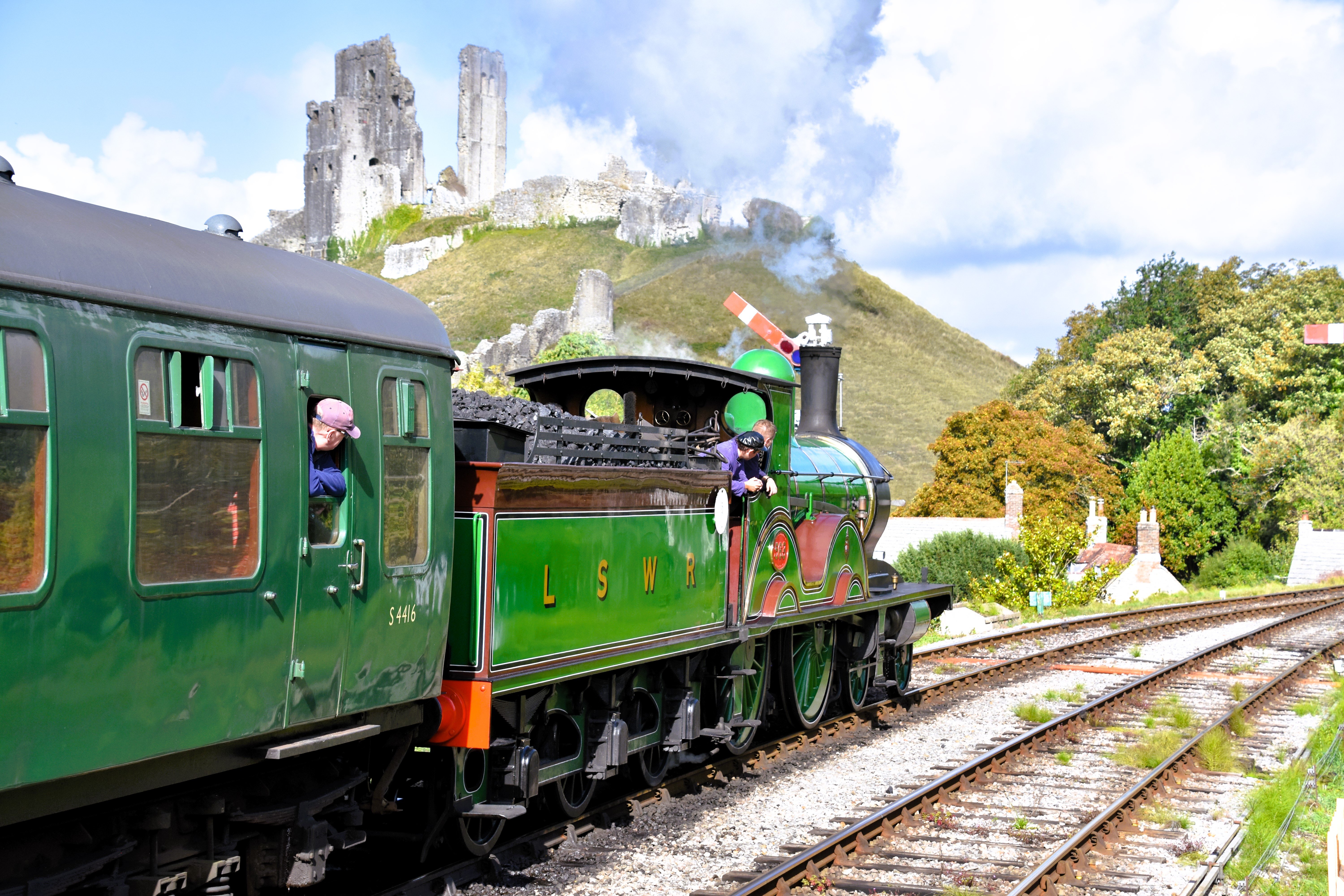
Post 6 Update In September 2025 three of my interests, Steam trains, the Paddle steamer Waverley, and castles, combined to make a wonderful holiday. 9567 I was hoping to see this locomotive dating from 1893, and it just happened that the Swanage Railway was holding its Autumn steam Gala during our stay. 9768 Here at Corfe Castle is probably the finest view from a Heritage Railway in England. 9410 I have long wanted to sail on the Waverley and there it was on a day we decided to visit Swanage and walk along the pier. A case of pure serendipity. On my return I didn’t have the motivation to continue work on my Erycina build, and there were other things that required my attention. Hence the four-month absence from MSW. Although still not fully fired up I now look to starting the first layer planking of Erycina. B.E. 30/12/2025


-
She looks a fine model fully rigged Glenn, well done. Too nice not to be on display. B.E.
- 241 replies
-
- 2
-

-
- Vanguarrd Models
- Harpy
- (and 1 more)
-
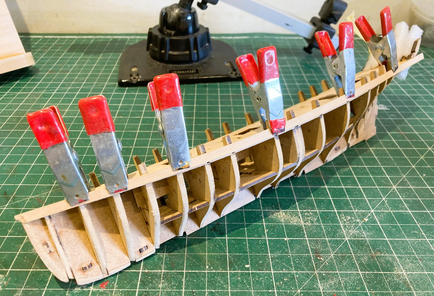
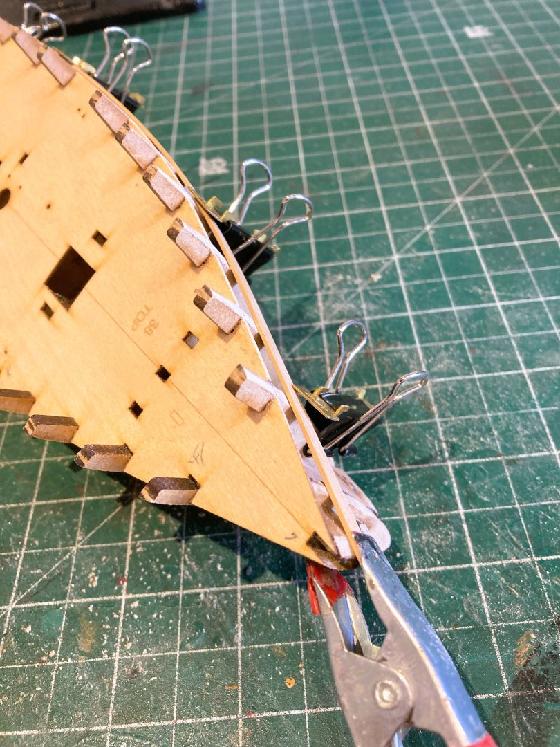
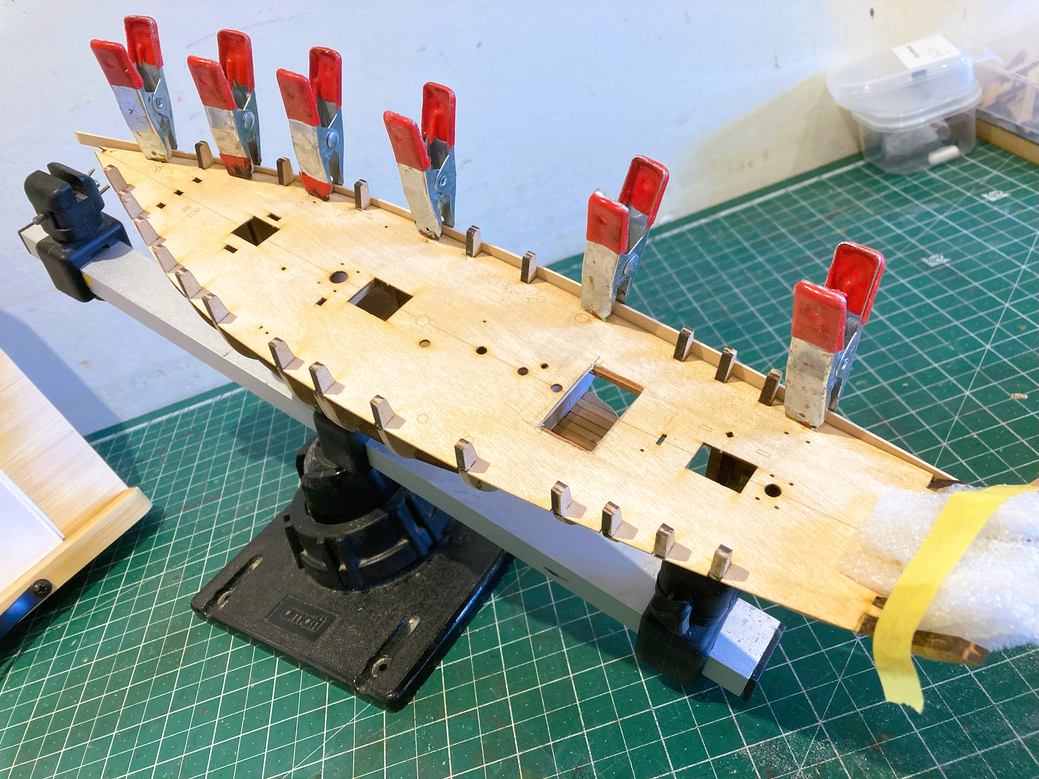
Post 5 Fitting the Bulwarks. As is usual with Vanguard kits the bulwarks come in two sections (Fore and aft) of 1mm Pearwood strip. They are marked on the interior with the frame positions and a useful fitting line which sits level with the deck line. 5623a I dry fit them and use heat to reduce the spring before gluing and pinning. 5650a 5652a Glue is not applied to the bulkhead extensions which are later removed. The stern counter frames require fairing to allow the counter pattern to fit cleanly across all frames. 5634a The counter pattern is wetted before clamping to the frames for better conformation and allowed to dry out. This can be speeded up by applying heat. 5642a 5645a With the bulwarks and counter in place the stern timbers are better secured against accidental damage. B.E. 06/09/2025


-
I regret to say that the cannon certainly is not a good example of a well made product.
-
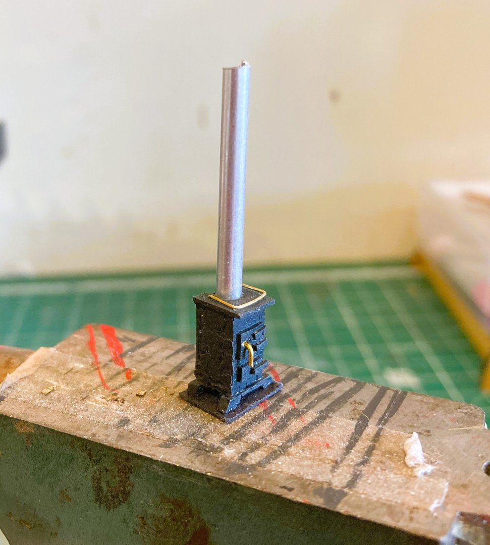
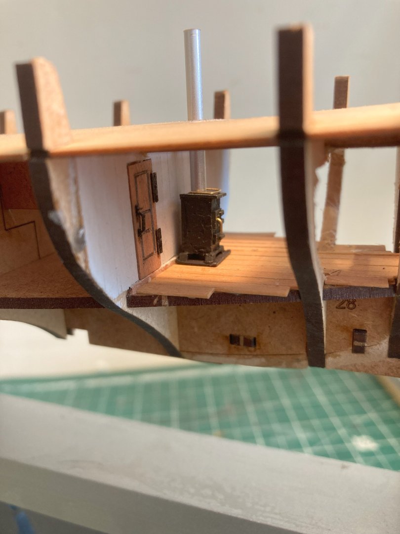
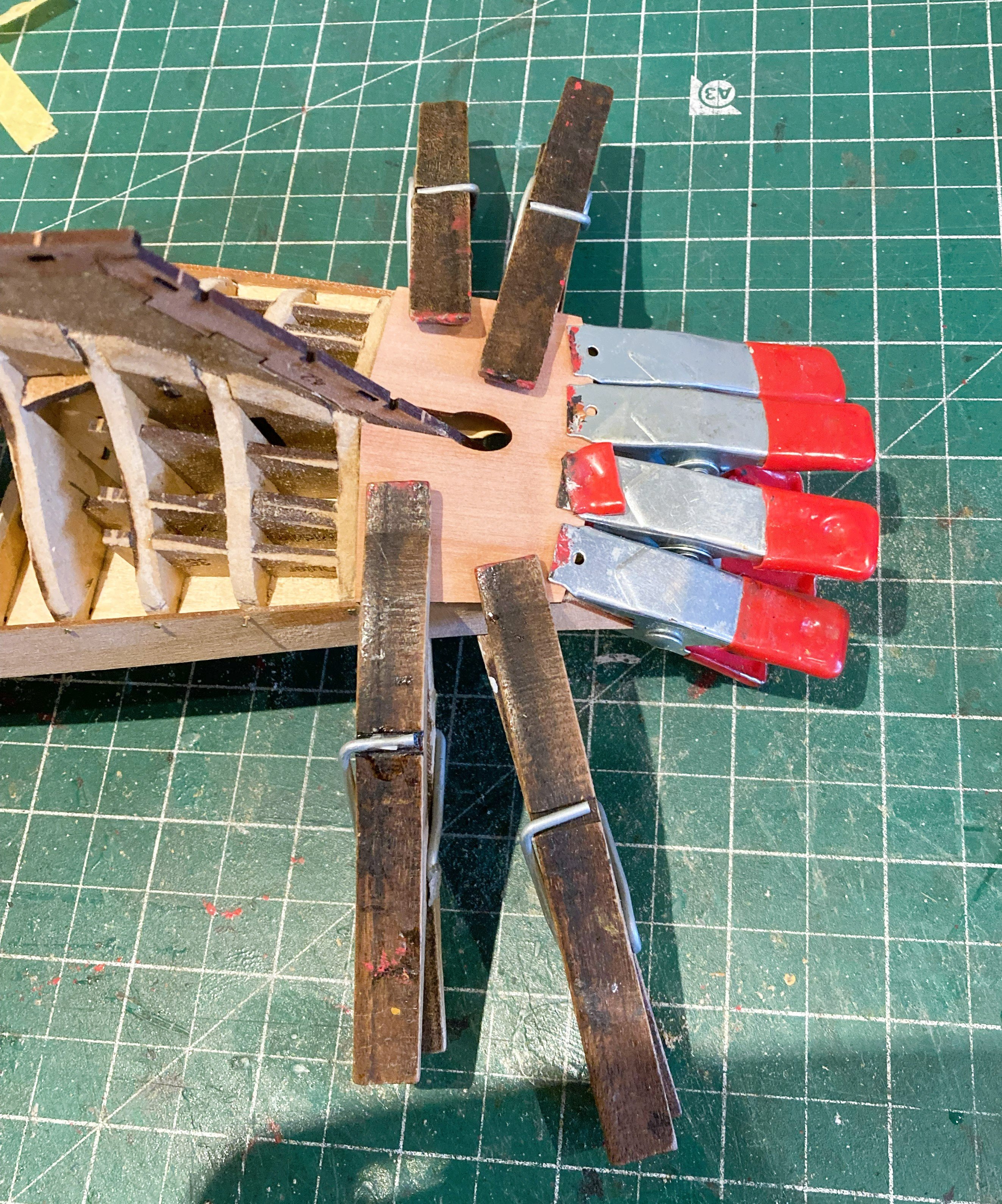
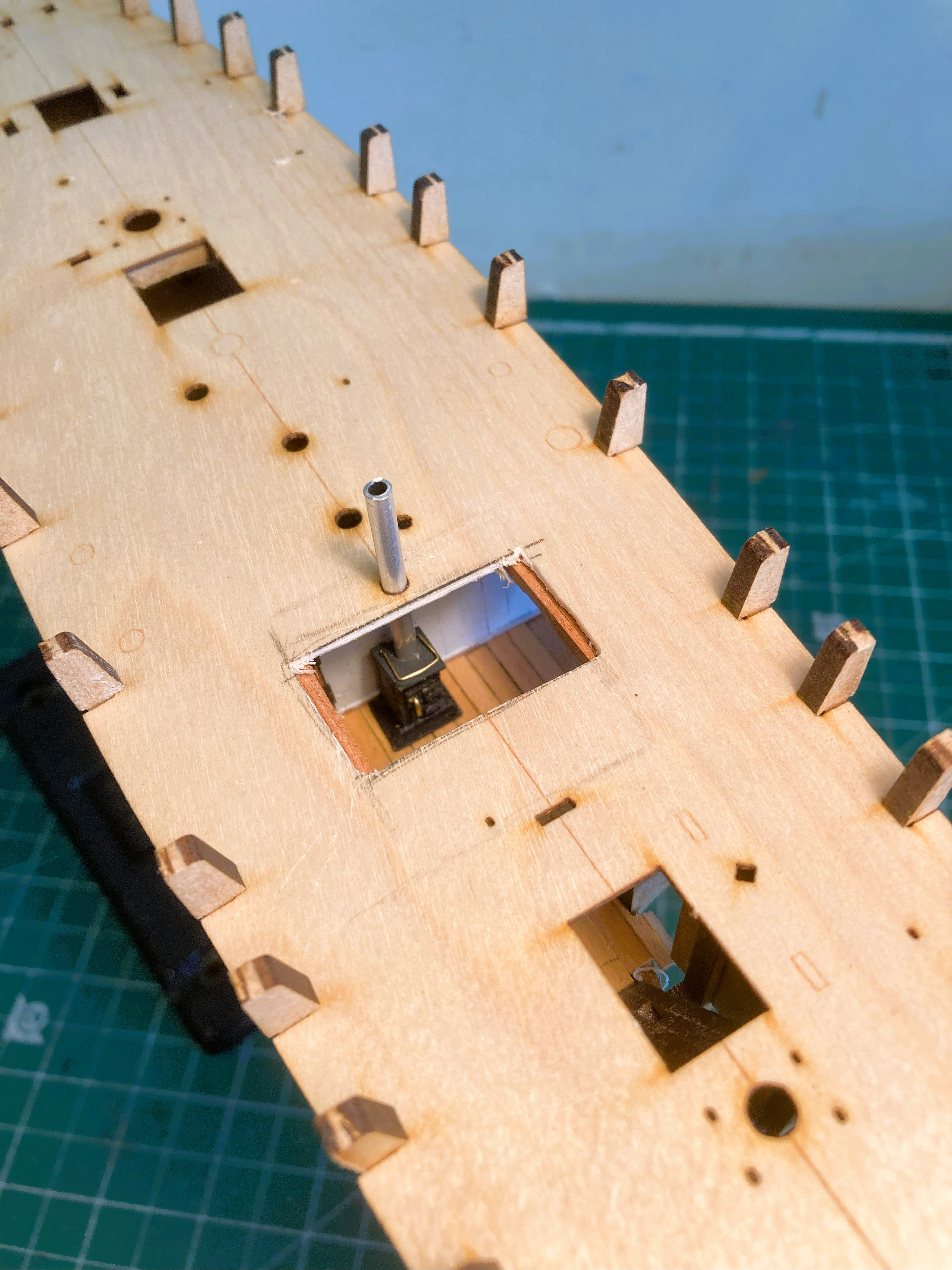
Post 4 Fairing and fittings A stove for Erycina It is certain that a small stove was contained within the cabin of Erycina but the kit only shows the Flue pipe emerging above deck. 5585a Before I begin fairing I knocked up a small stove to check the fit and position for the line of the flue pipe. It is a tiny thing measuring only 12mm x 6mm. 5593a The main objective is to see how it looks in the cabin position. 5595a I think it will pass muster, at least to a blind man on a galloping horse. Fairing is straightforward on Erycina, it’s nice to have a hull that will fit in one hand to work on. 5600a 5604a A careful check is made to ensure that a test board will fit tightly against the deck edge and bulkhead ears. 5607a 5608a Similarly, all points of the faired bulkhead edges are checked using a test board to ensure full contact down to the keel. 5612a 5616a 5620a The final stage of this section is the addition of the Pearwood keel, Bow and sternpost parts. They all slot perfectly together into the false keel. B.E. 03/09/2025


-
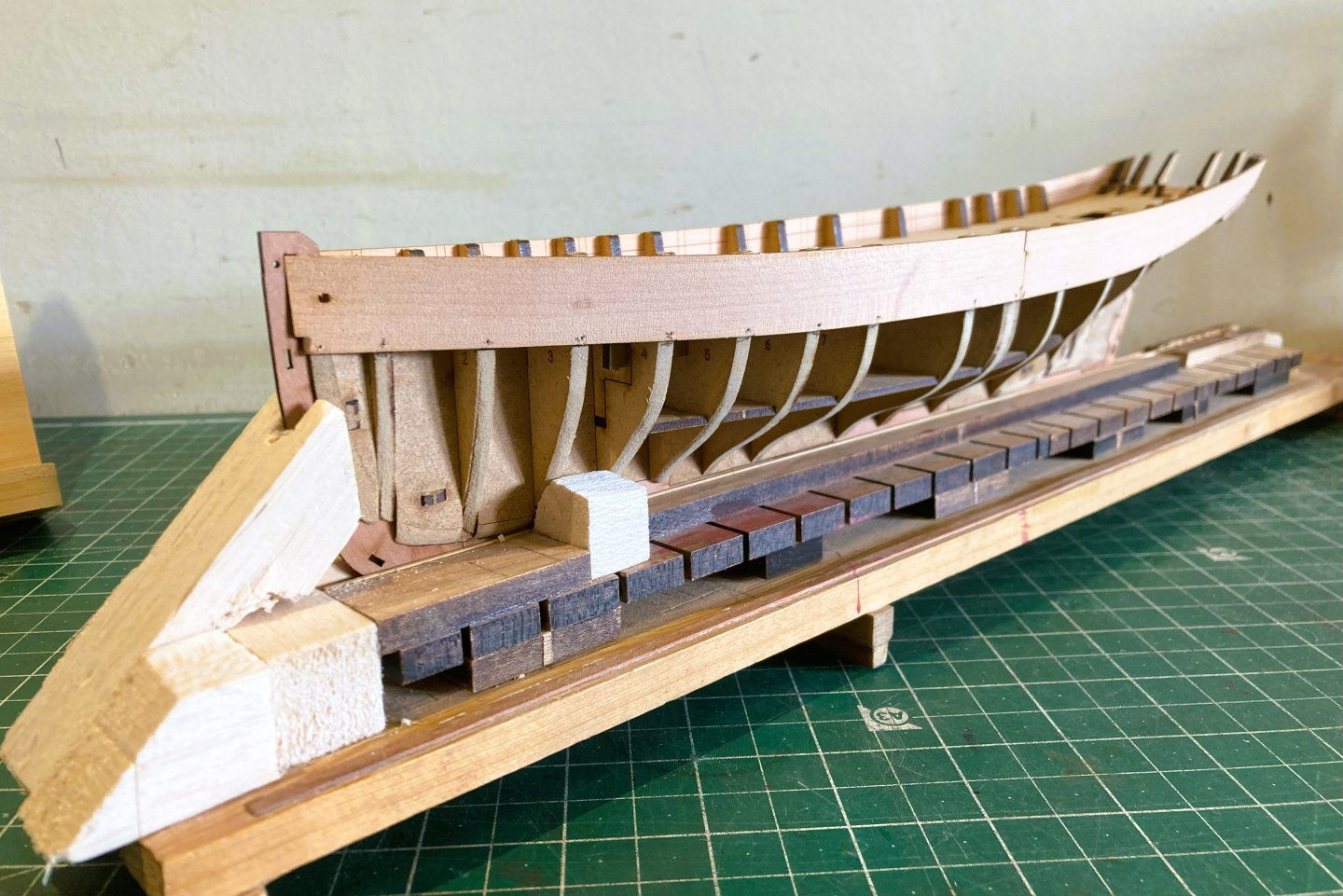
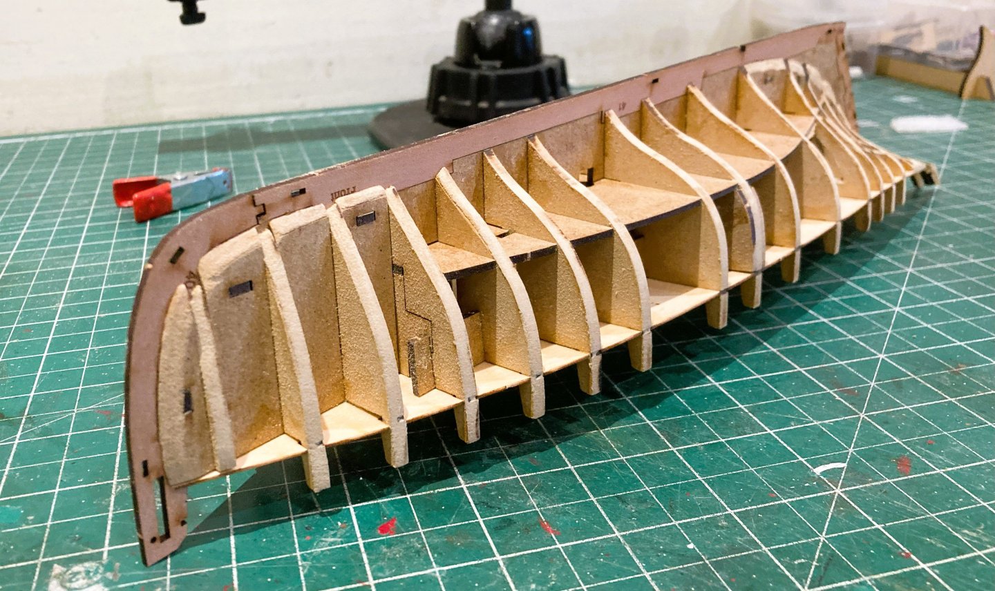
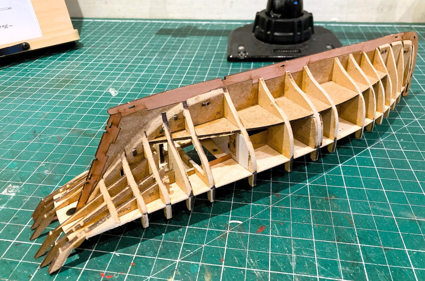
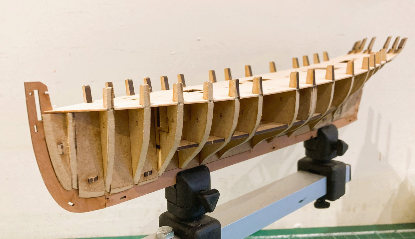
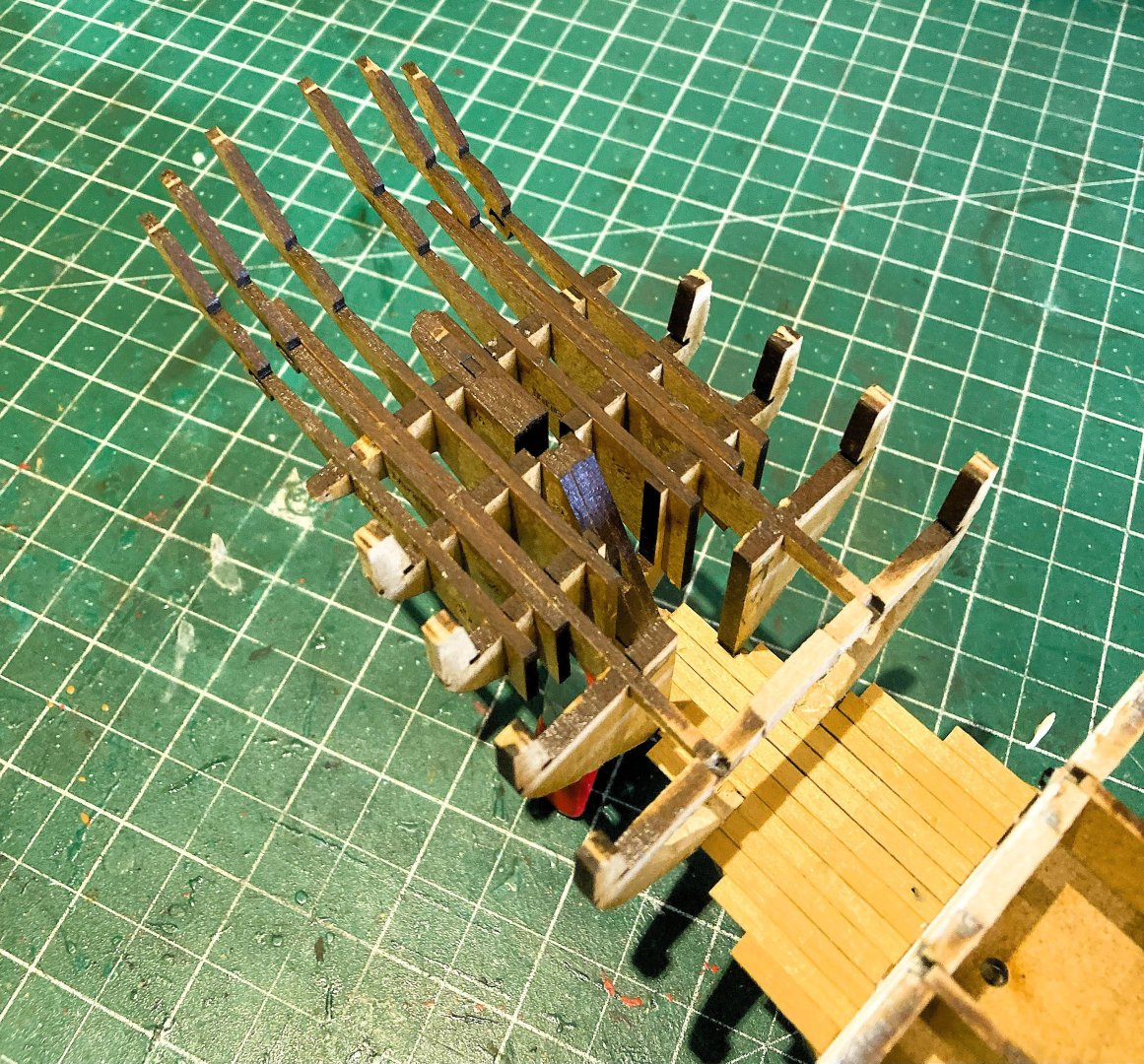
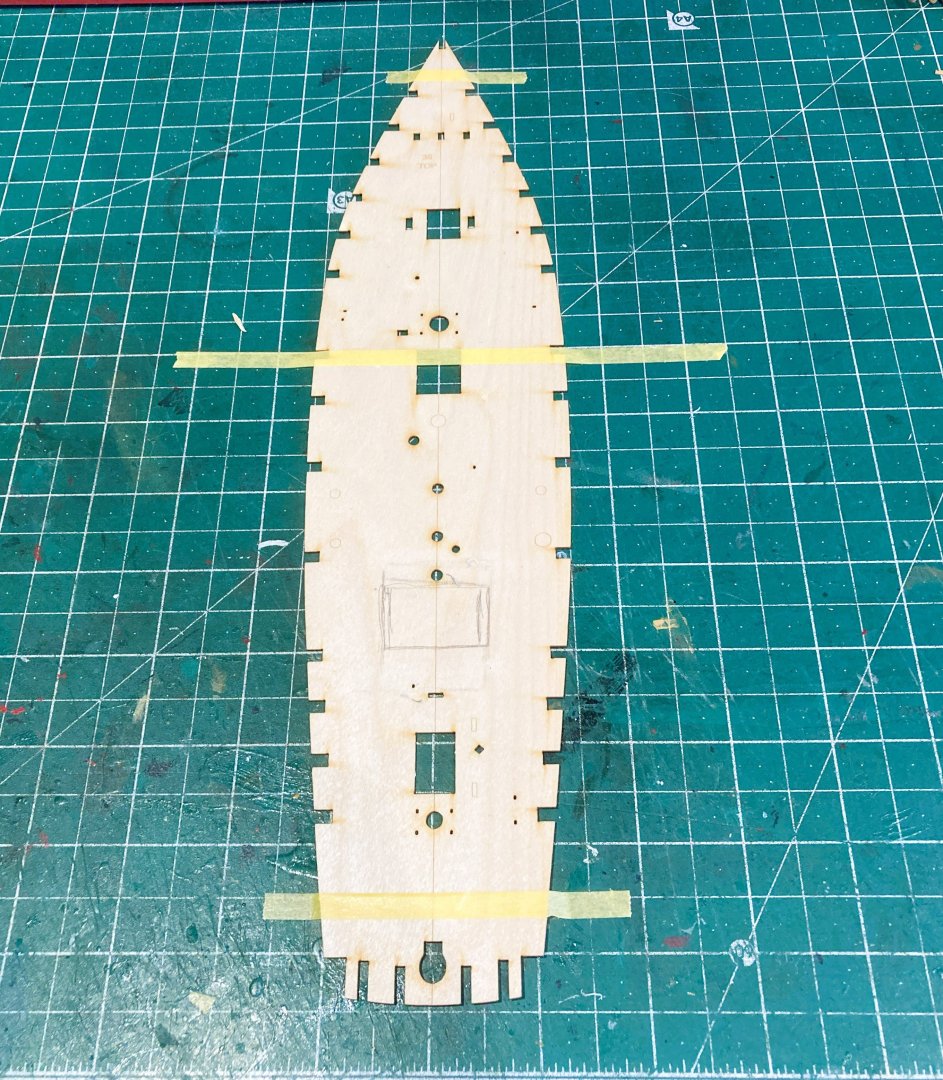
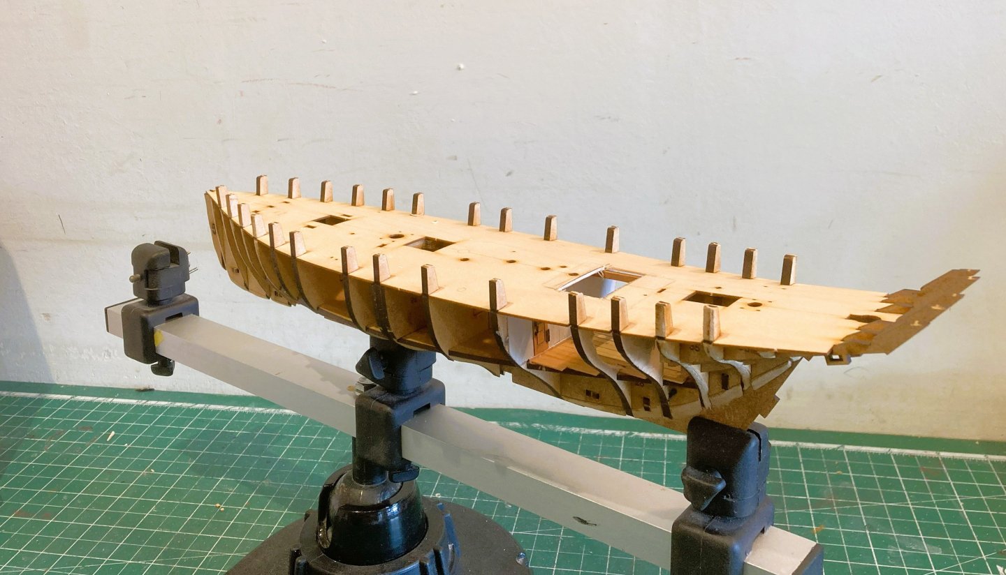
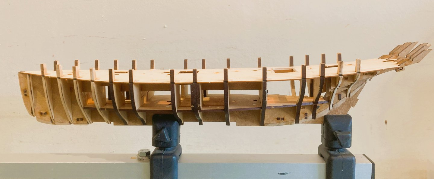
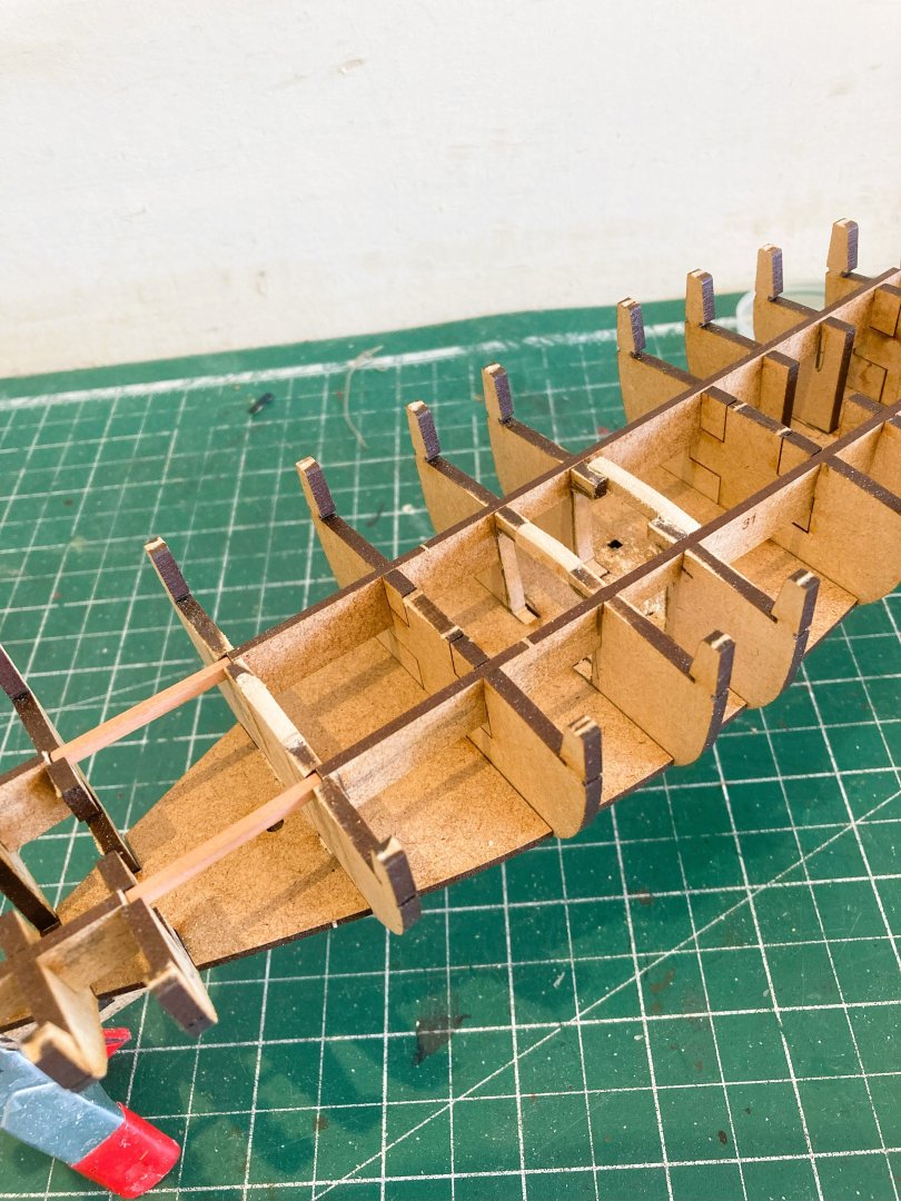
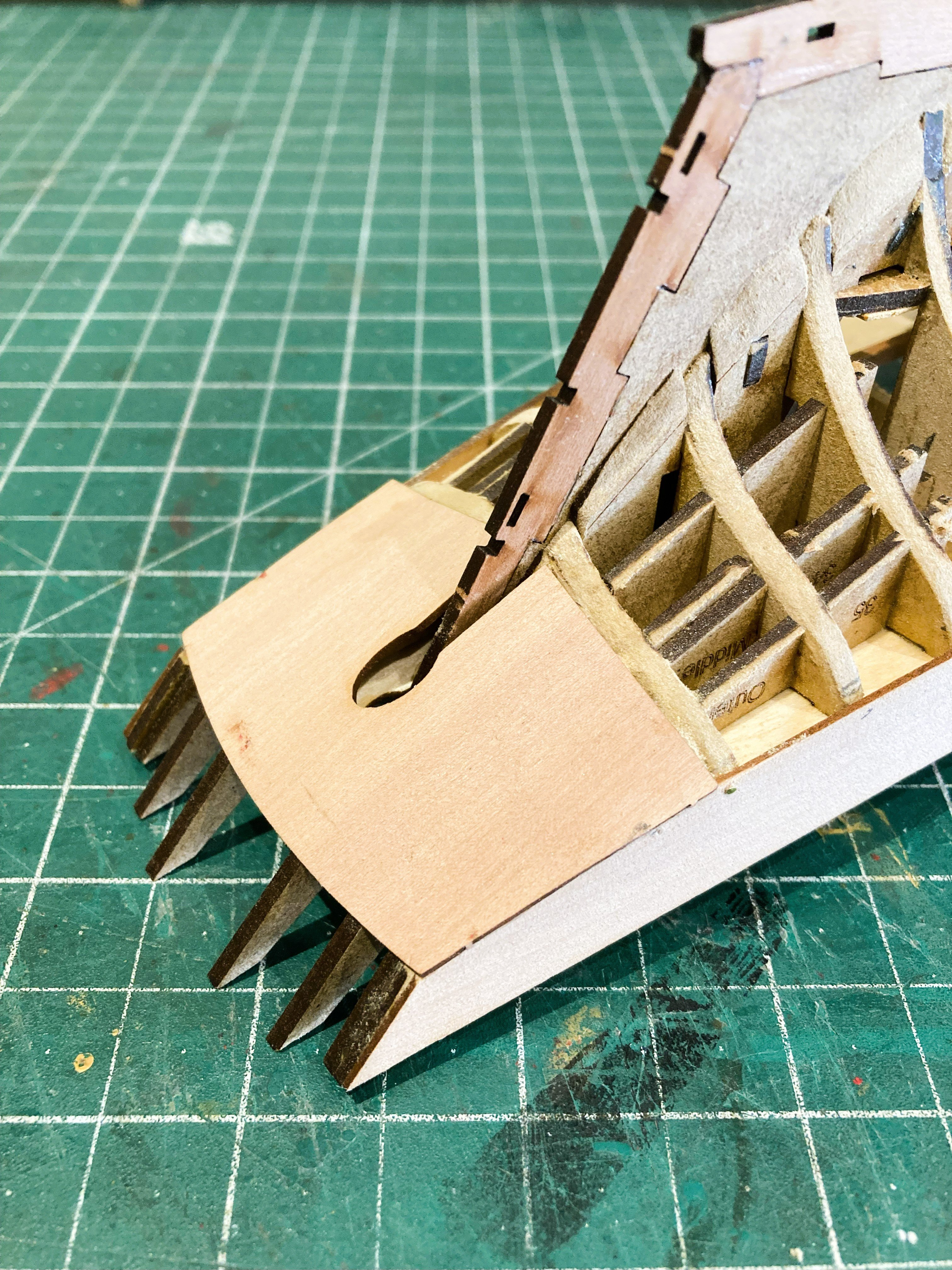
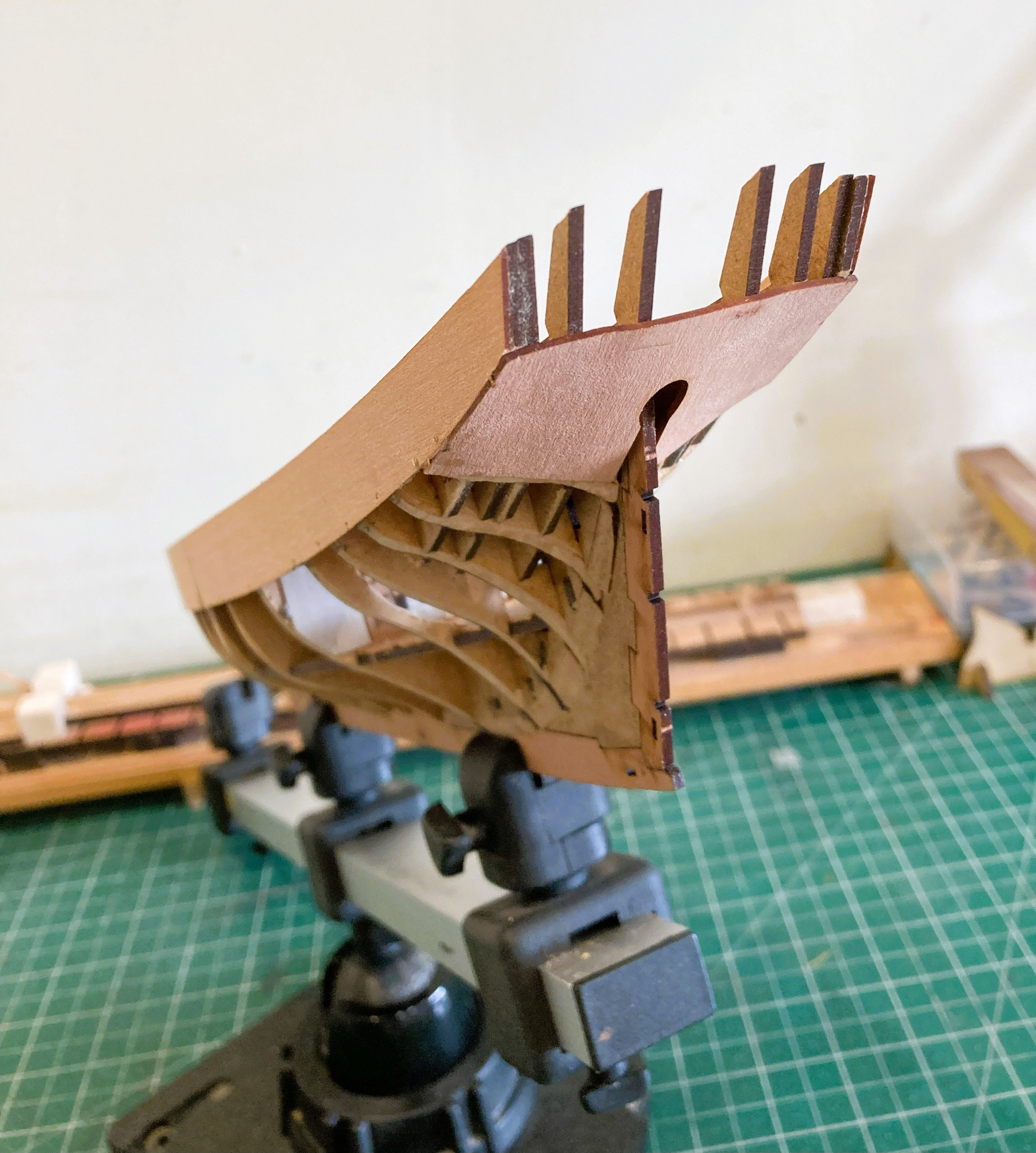
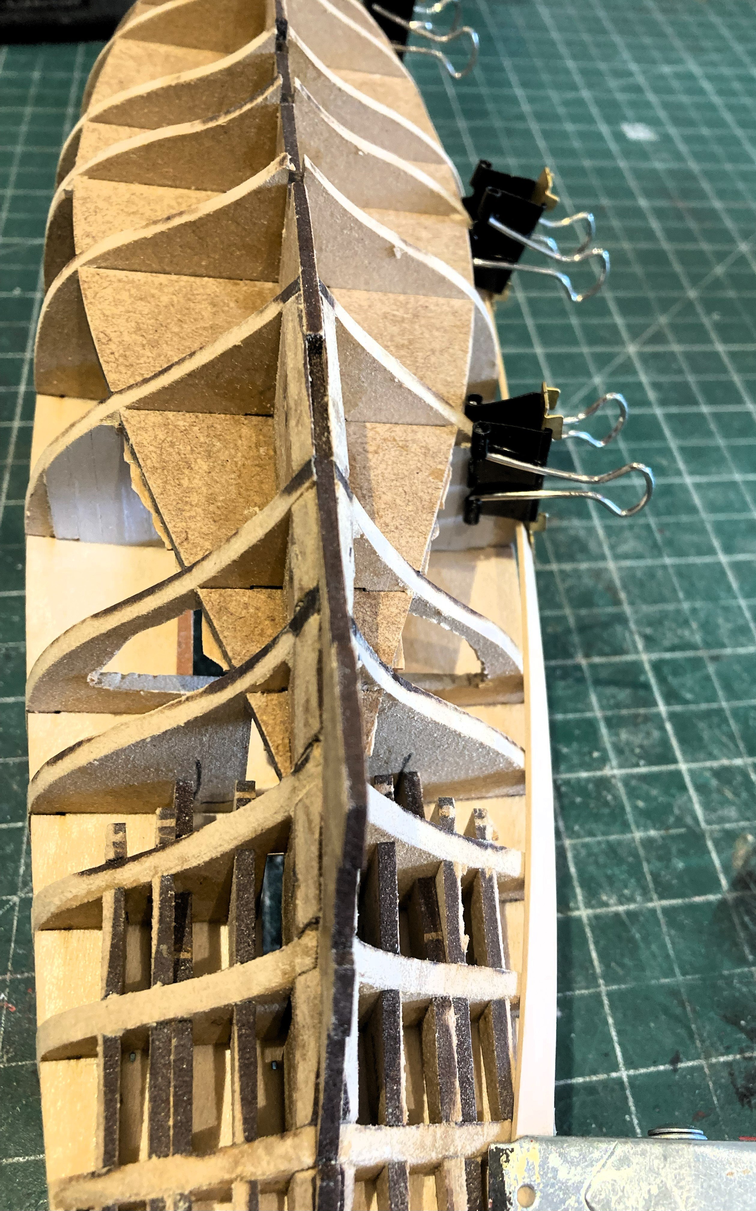
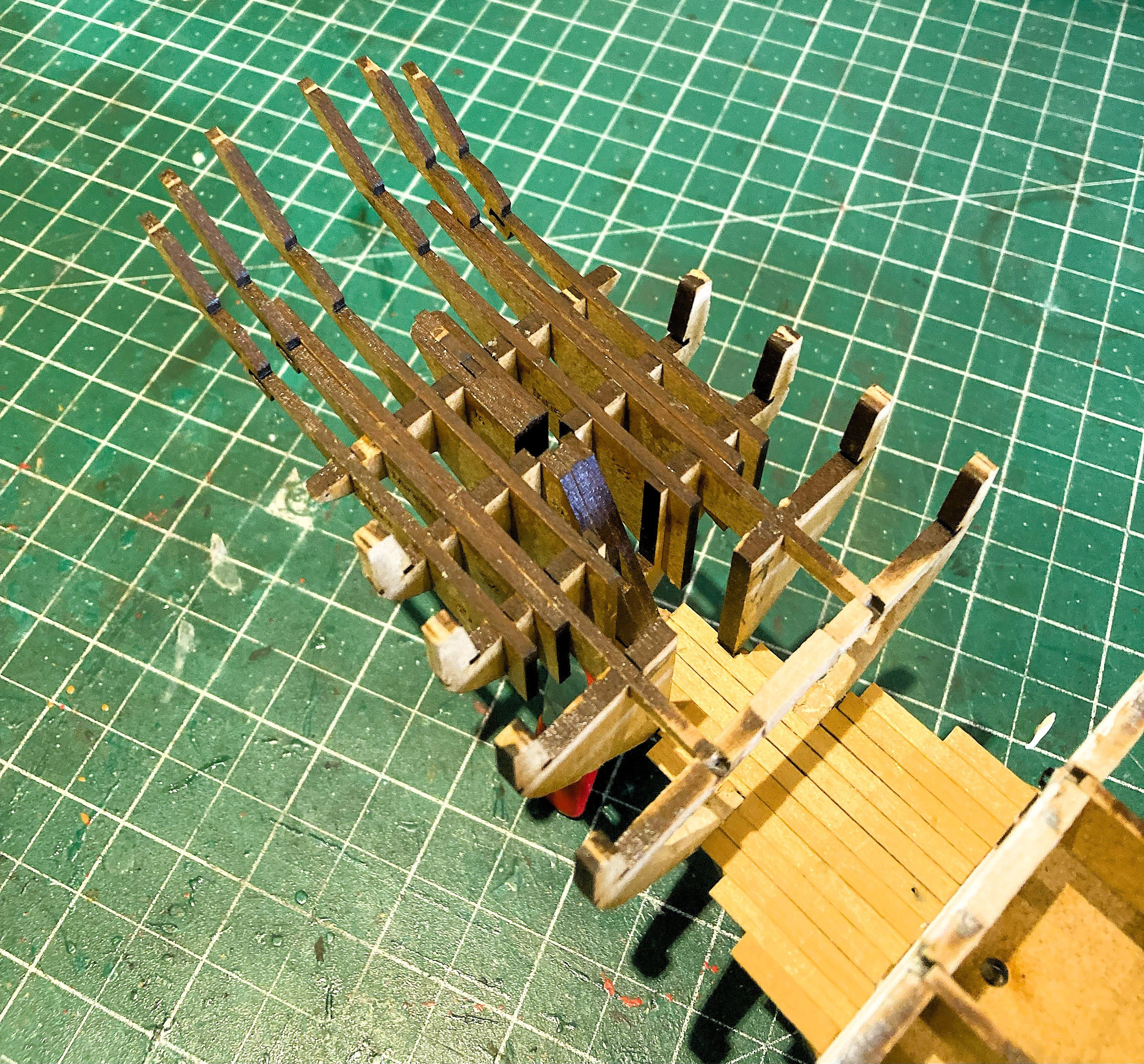
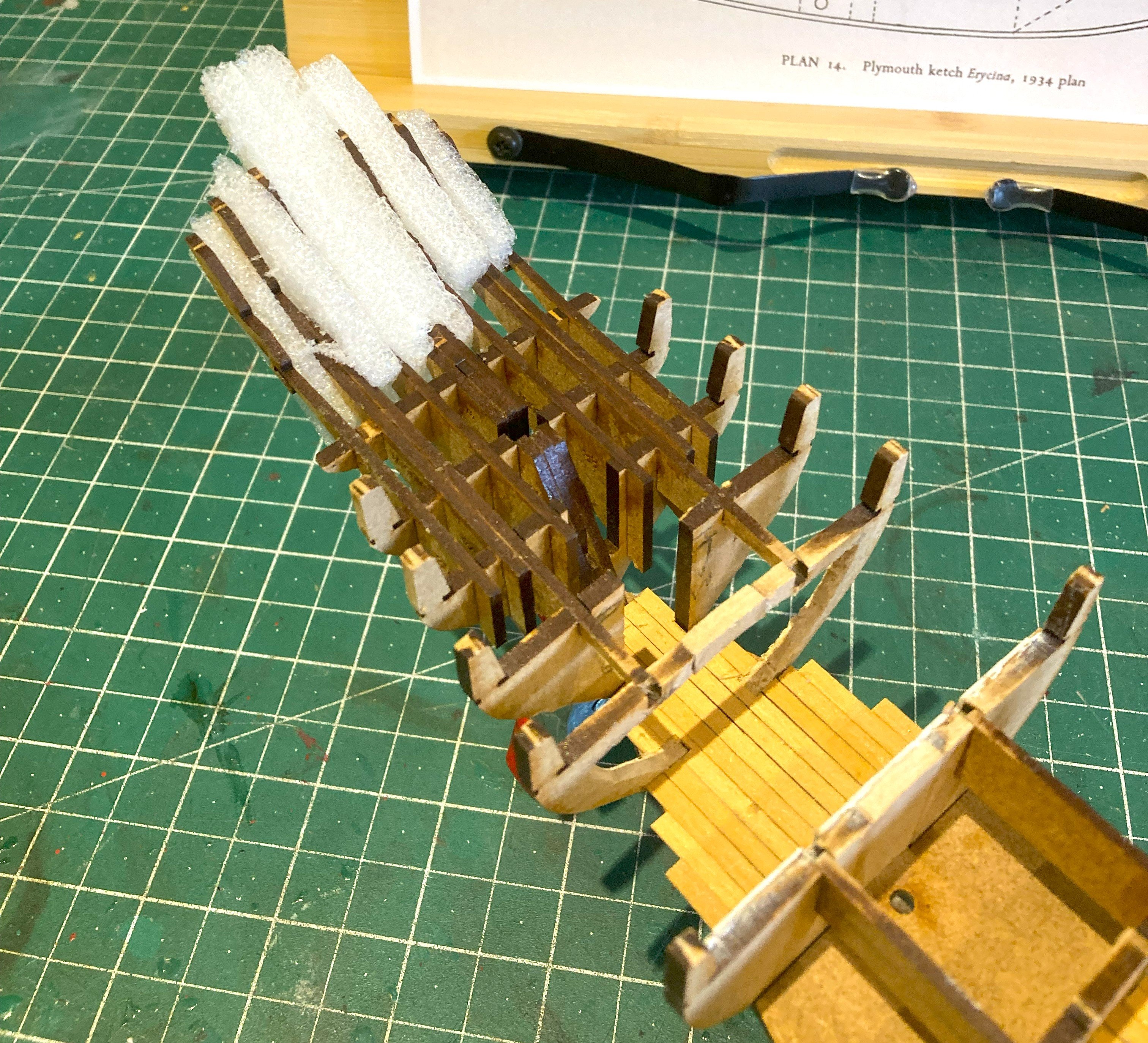
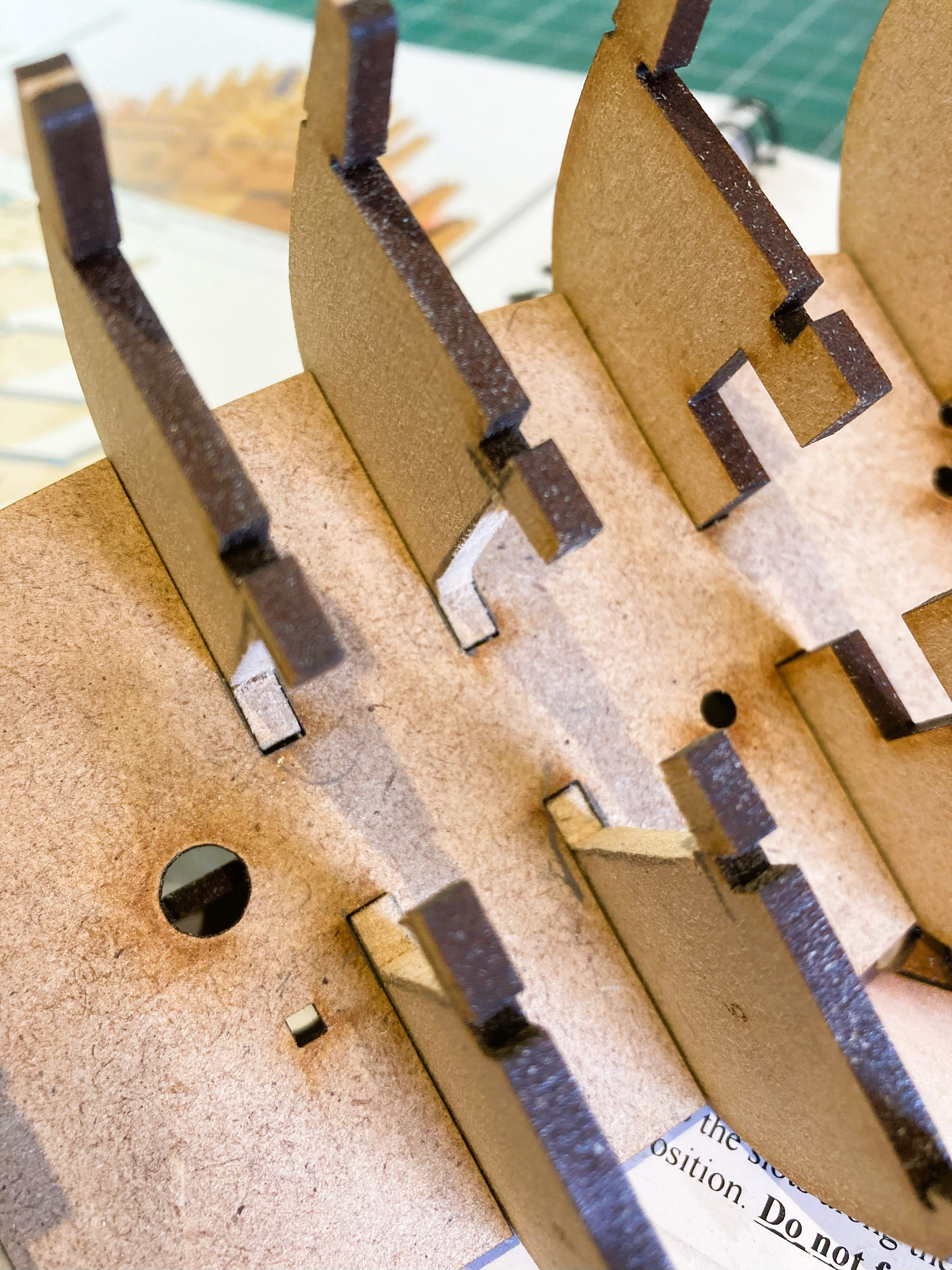
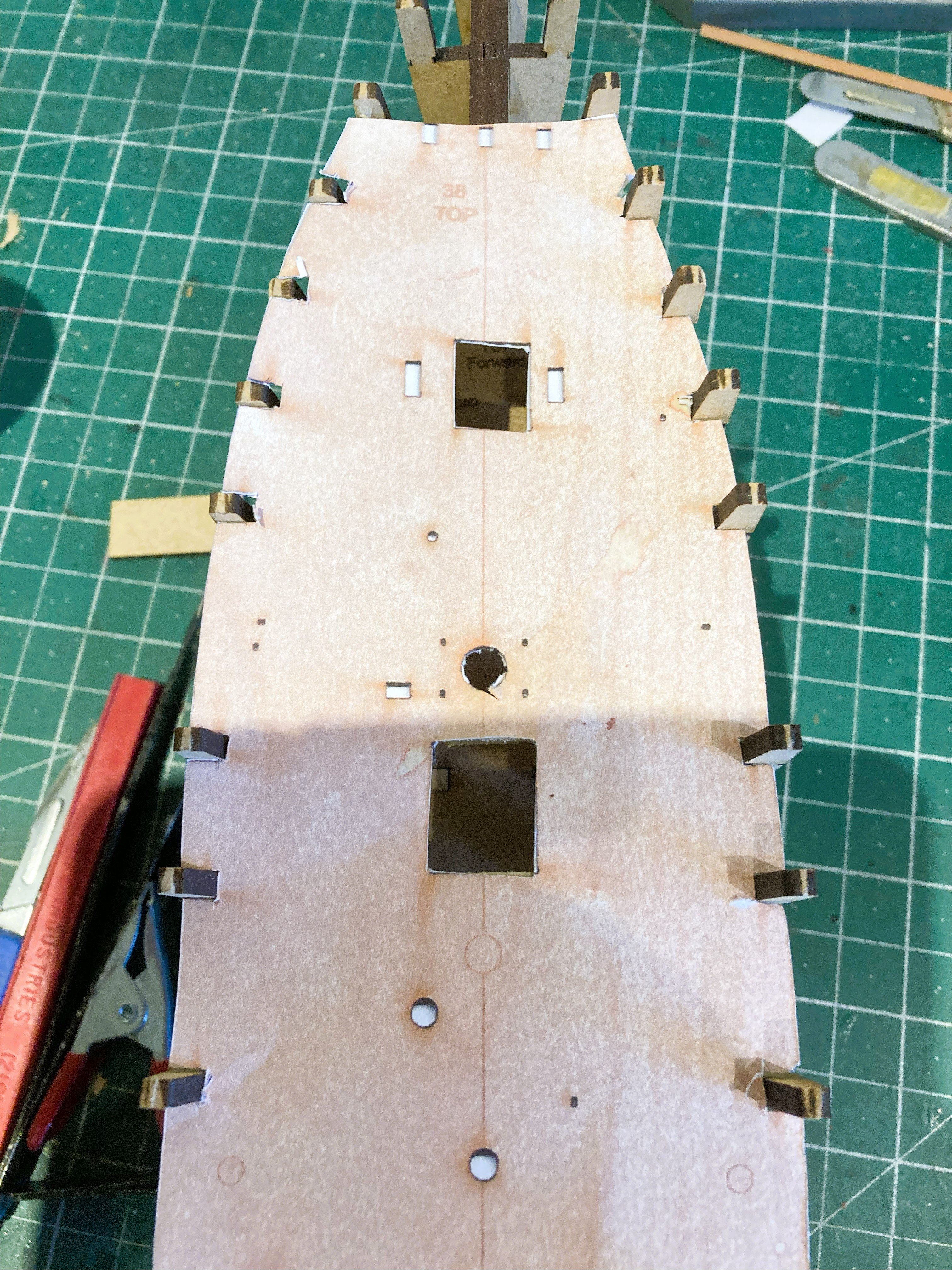
Post 3 Stern timber frames These are the long and vulnerable mdf stern timbers that set alarm bell ringing in my ears. Great care is required not to stress or knock in the early build stages; repairs could prove tricky. 5572a I found that careful sanding of the slots, and trial fitting was required to achieve a firm but not overtight fit which may have created difficulty if subsequent removal was necessary. 5573a Fitting support pieces between the timbers is advisable. I use styrene foam pieces which are ideal. Once the bulwarks are fitted this area becomes less at risk. 5567a 5569a This is now the time to fit the ply sub-deck which will secure the bulkheads from lateral flex during fairing. Another testy little exercise. 5580a The deck is taped square on the cutting mat to mark and remove the section above the cabin, a margin is allowed for some final trimming. 5582a The bulkhead slots are tested for ease of fitment and having fully inserted the deck into the port side slots I work along the starboard side from fore to aft individually flexing and pressing the deck into place at each slot. 5584a There is always fear of breaking something with this exercise, but firm and steady pressure get the job done. I was pleased to see that the deck sits tight against the bulkheads and stern timbers, no pressure necessary to hold the deck down. The hull is now rock steady for the fairing process to begin. B.E. 01/09/2025


-
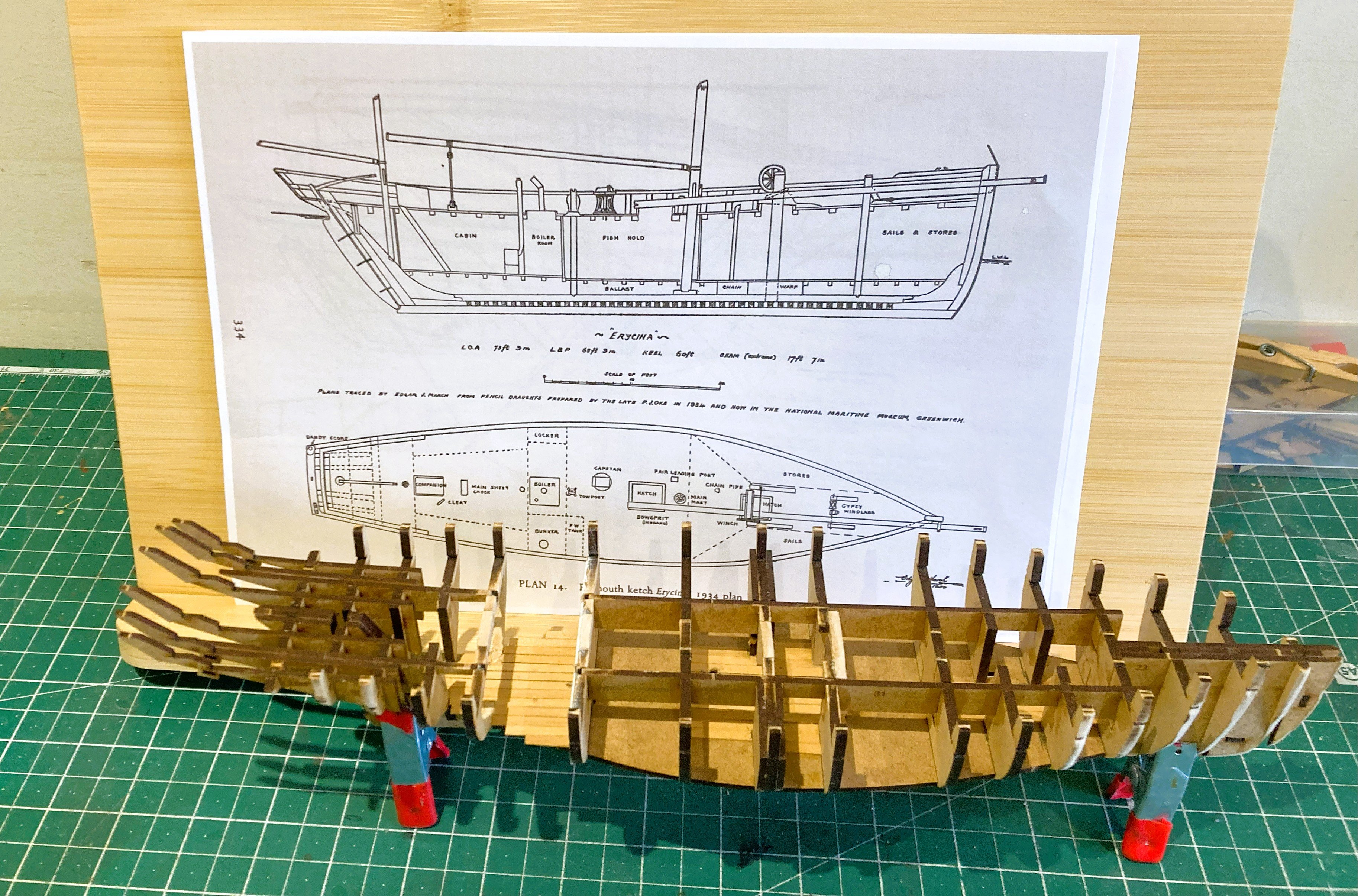
Hi Chris, I tend to choose kits where I have additional information; in the case of Erycina I have the internal layouts drawn by Edgar March, and a wealth of given sizes and rigging detail, contained in his book Sailing Trawlers. I used his companion book Sailing Drifters when I converted the Zulu kit to Muirneag. I then look at the kit and decide where I can enhance the detail which often develops organically. I do draw things out to scale where needed, and with deck cut-outs I use copies of the kit decks to work the final arrangement. I suppose after many years of messing around with kits I have the confidence to chop them around, but this is becoming increasingly less necessary with Vanguard kits as Chris develops more and more lower deck detail and associated fittings. Regards, B.E.
-
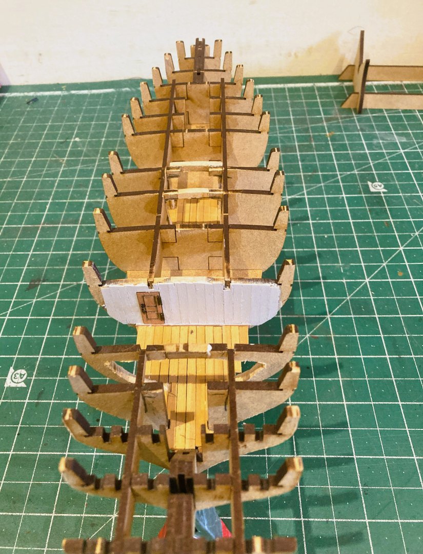
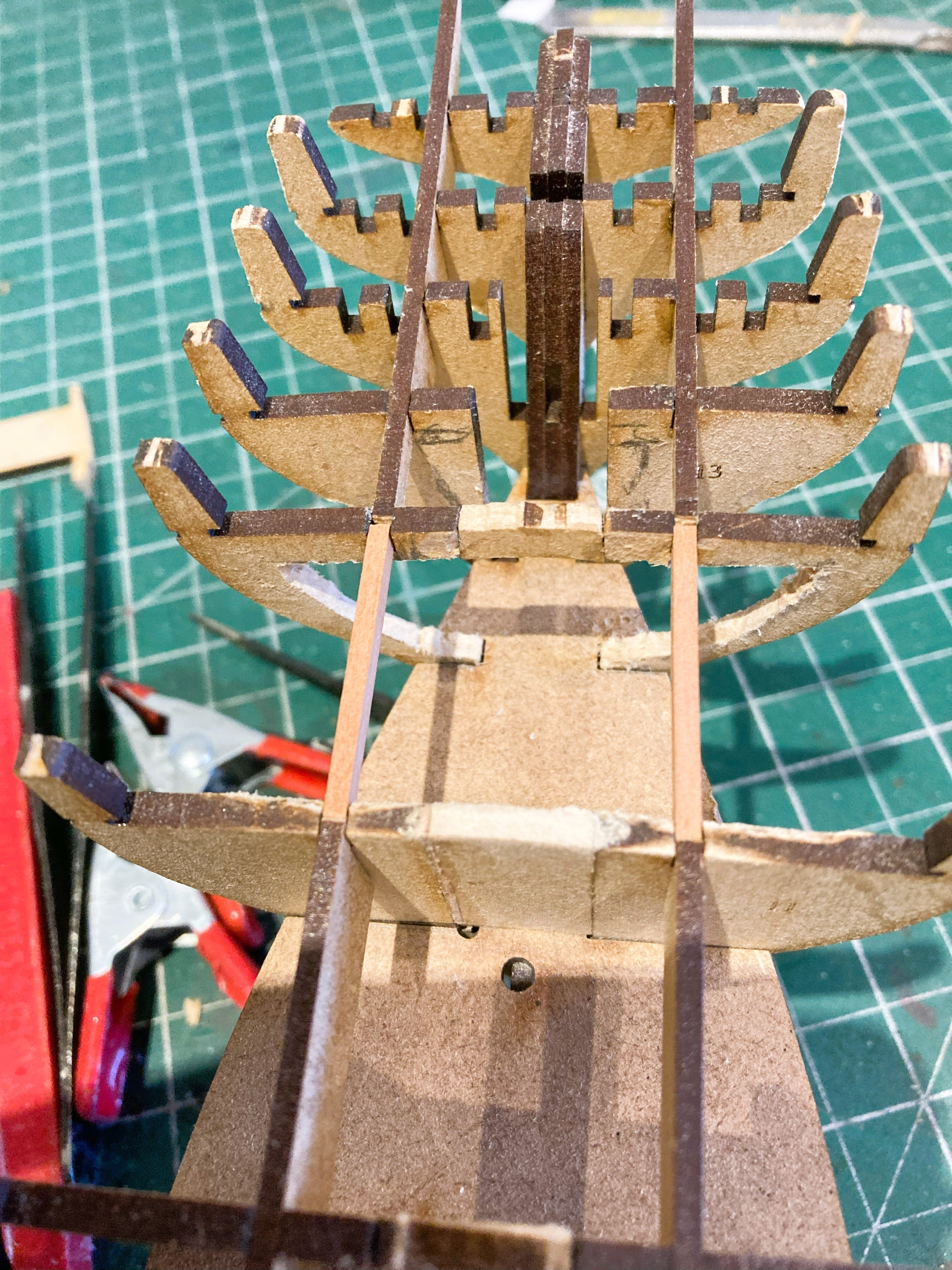
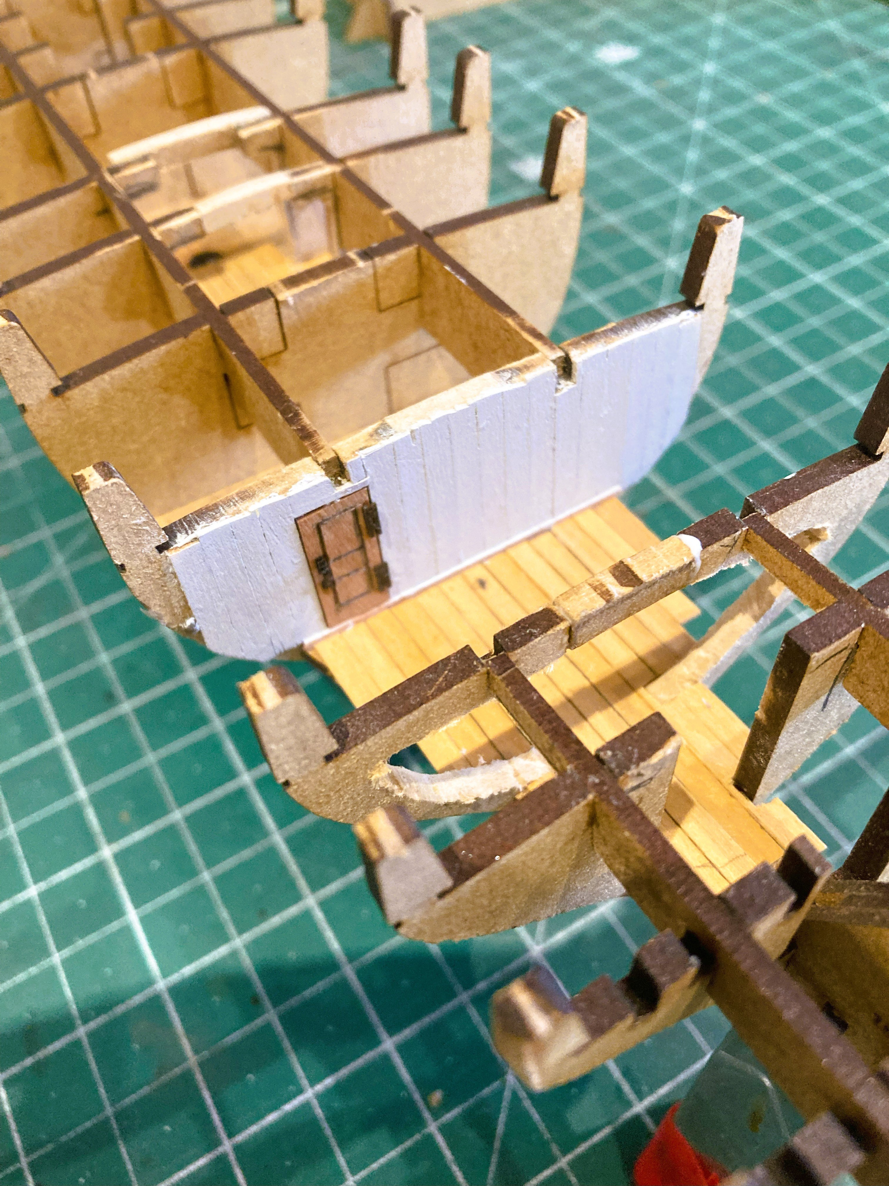
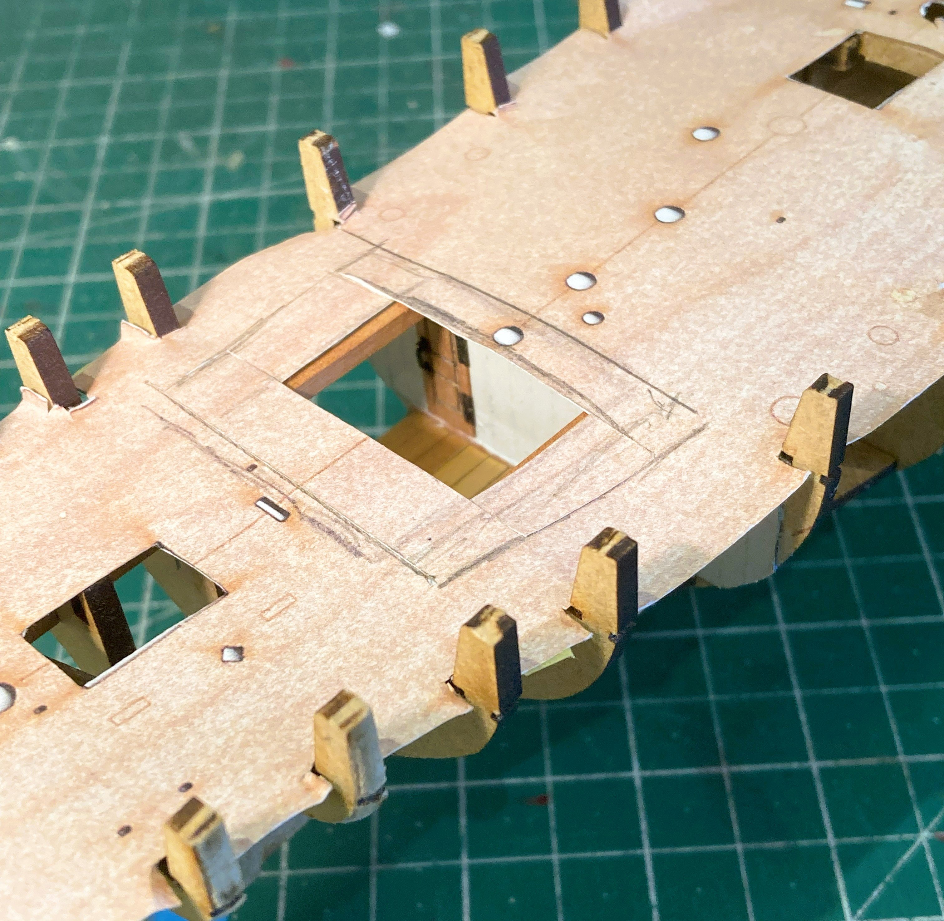
Thankyou Trevor, makes a lot of sense.👍 Post 2 Stern cabin area My idea is to fit out the cabin, certainly with the iron stove which will connect to the flue pipe emerging thro’ the deck, and maybe with other fittings as space allows. A section of deck will be left unplanked above the cabin. Modifying the cabin area is tricky, partly because work on Bulkhead 12 is more extensive, and because it proved too difficult to remove for shaping without risking damage and therefore had to be modified insitu. The filler pieces between the bulkheads prevented removal. Bulkhead 11 is closed off as this forms the partition between the cabin and the Boiler room. Bulkhead 12 bears the brunt of modification with large sections removed to create frames and beams. Tricky to get at to shape and sand. 5552a In this area the longitudinal bracing patterns are removed and replaced with Pear carlings. 5553a Bulkhead 11 is boarded using Boxwood strip and Whitewashed. A doorway leads to the Boiler room and the door is created from Boxwood strip and decorated with Syren hinges and Handle. 5554a 5557a The cabin deck area is planked with Boxwood strip. 5559a Similarly, the Fish hold is decked out using Boxwood strip. 5565a A paper deck print is used to determine the viewable area. Still work in progress, but you get the idea. B.E. 31/08/2025


-
Thank you Ron 👍 @ Palmerit - I hope to do a little more than that.🙂 Cheers, B.E.
-
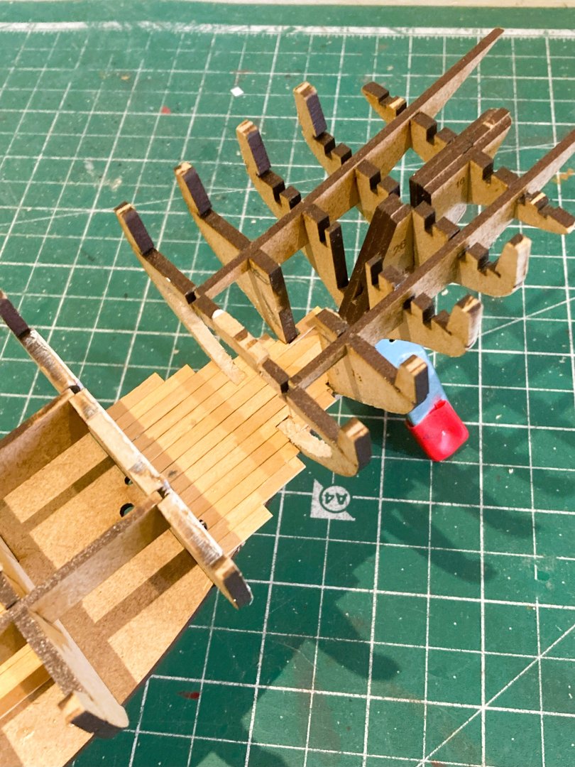
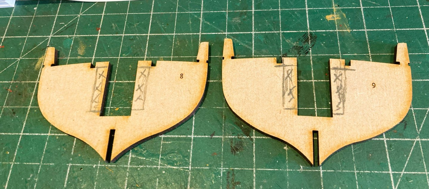
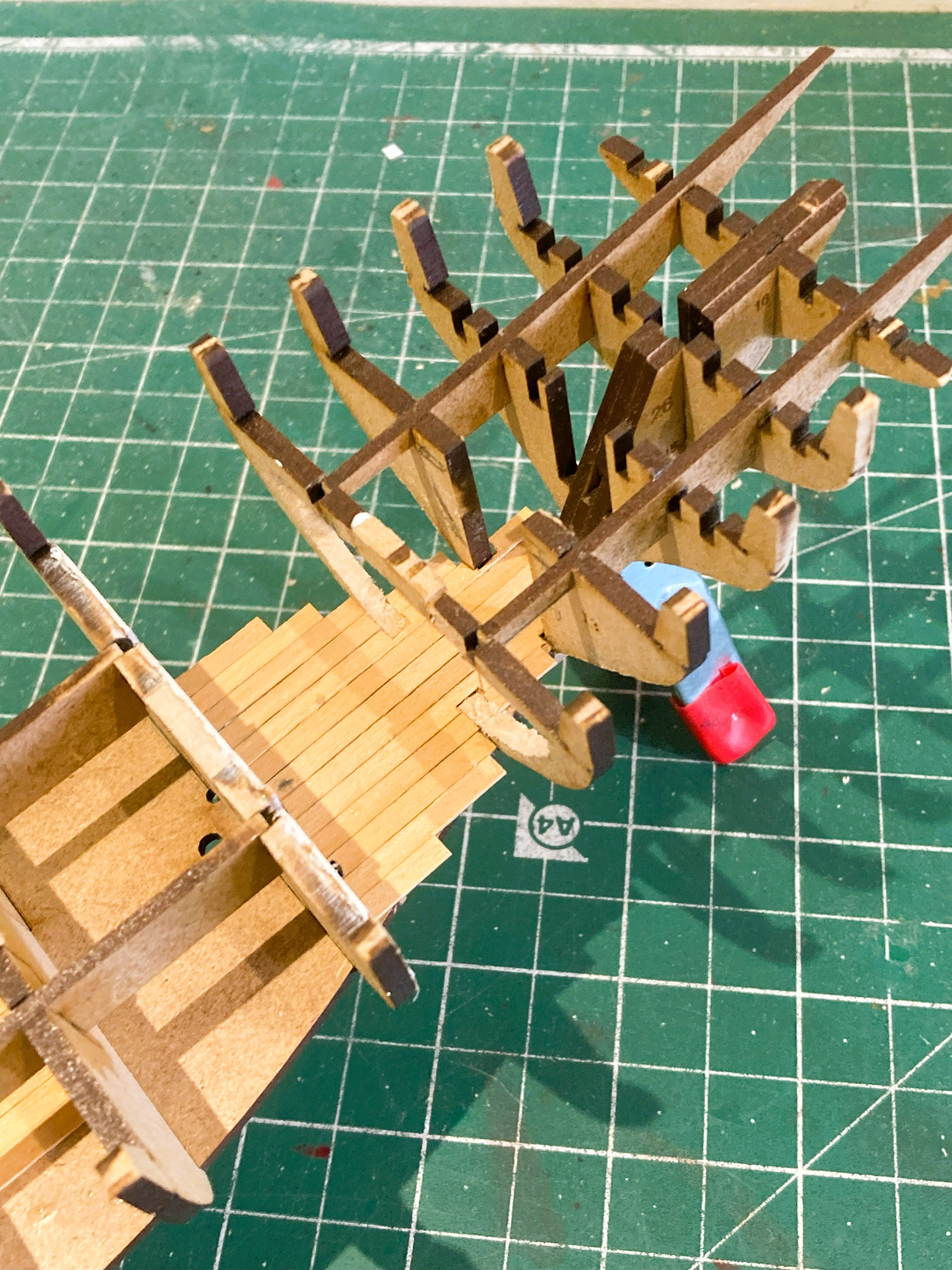
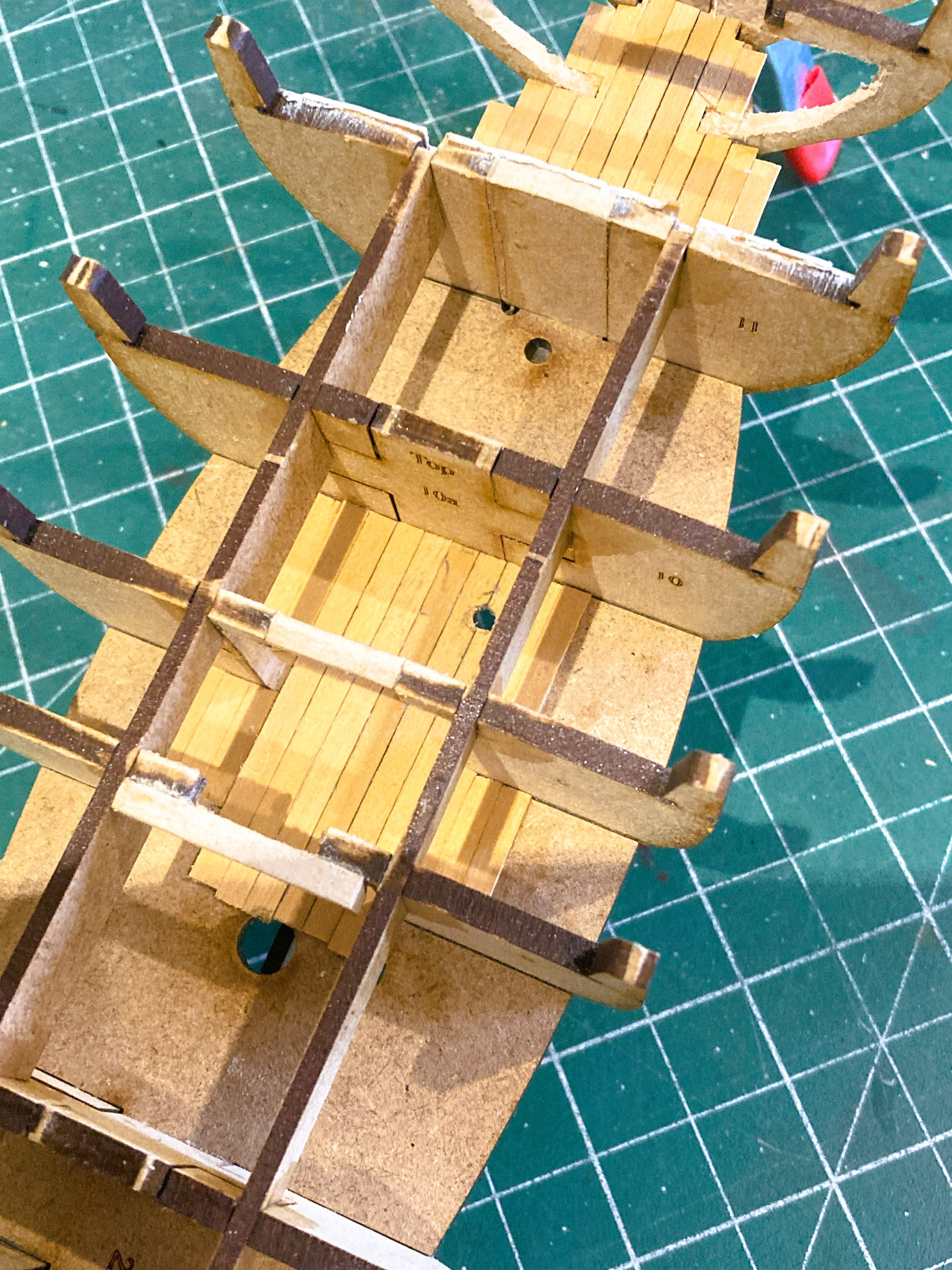
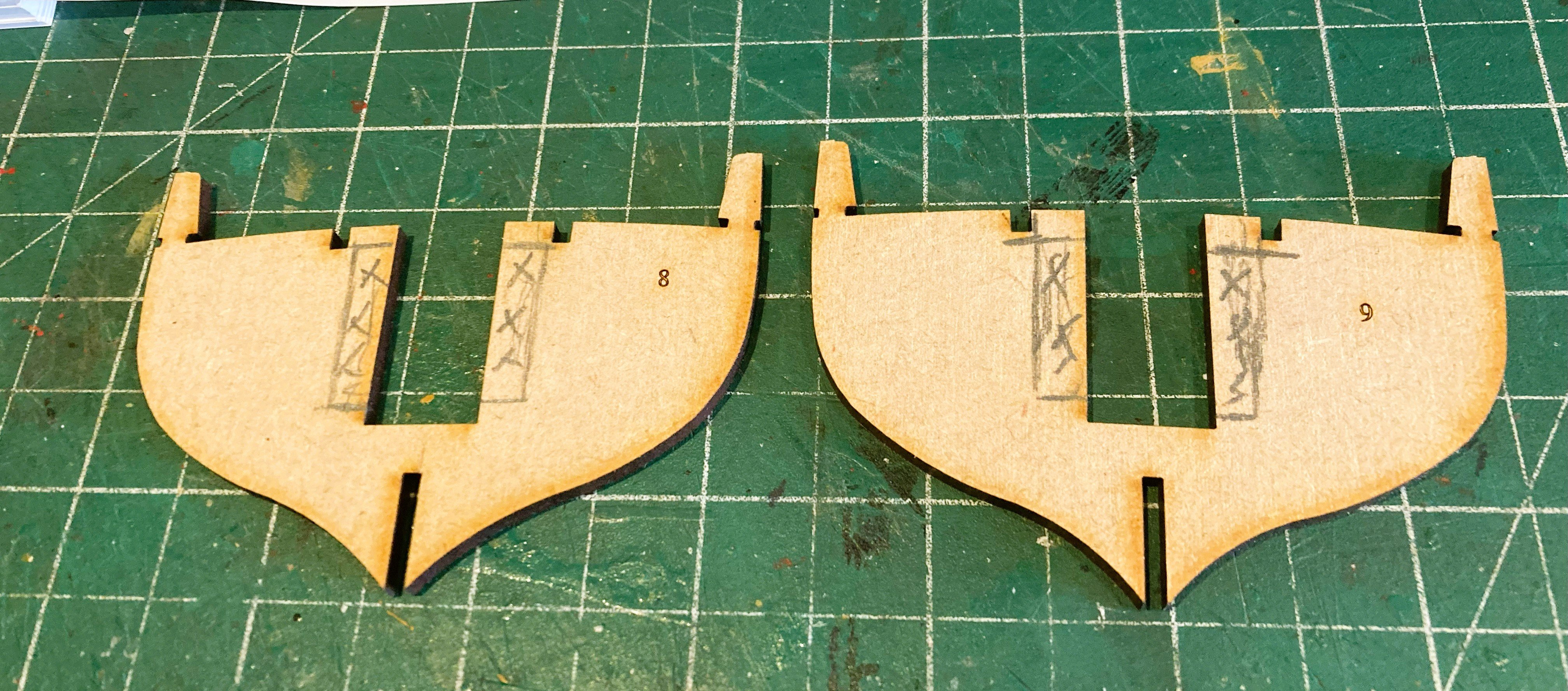
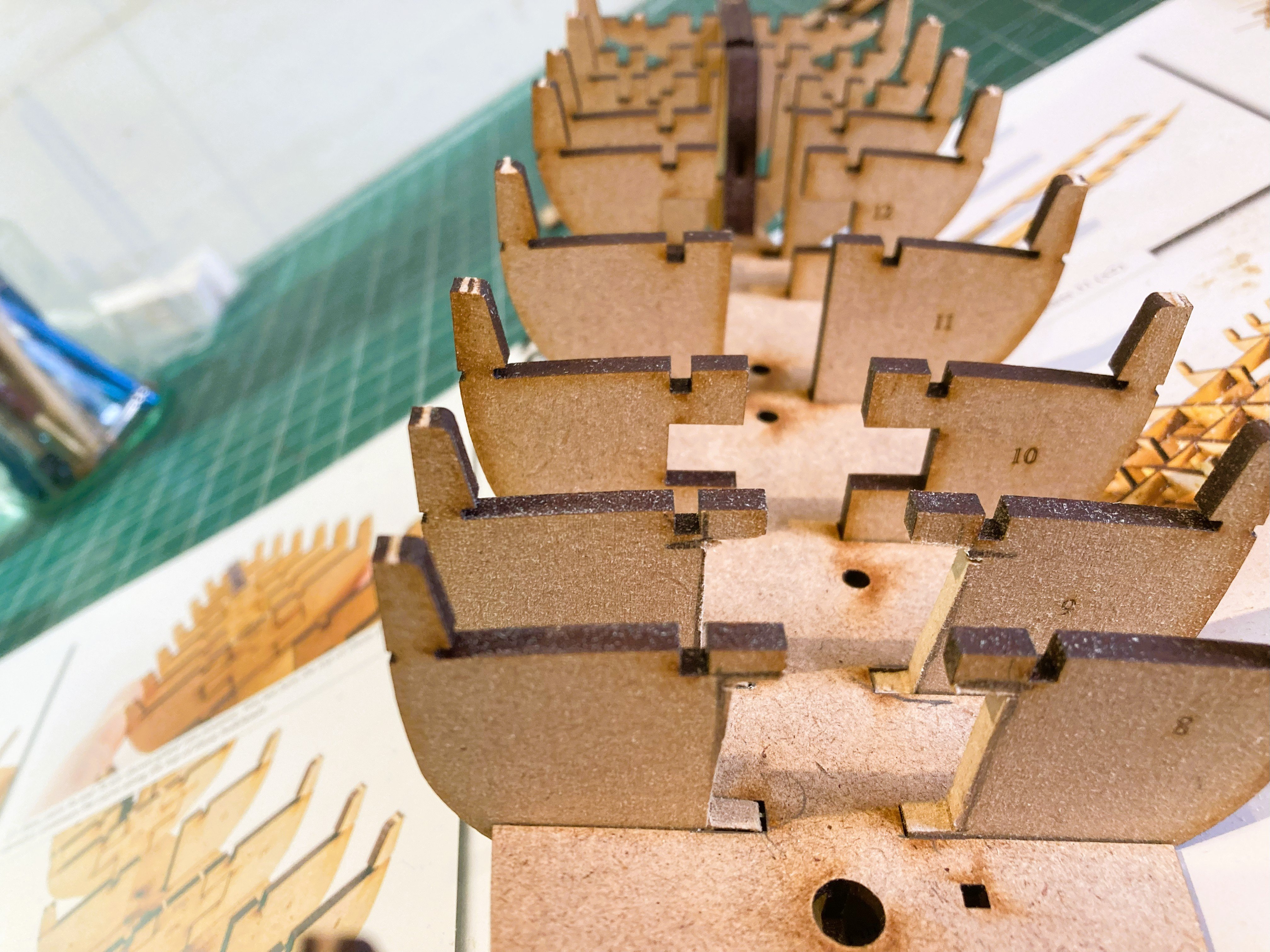
Post One Early stages The early stages of construction are just as we have come to expect from Vanguard. 5534a Rapid early progress with glueless assembly of perfectly fitting parts. That is unless you decide to open up the lower deck areas of the Fish hold and the cabin space. 5537a This involves some modification to the Bulkheads 8 and 9 ( in the case of the fish hold, and Bulkheads 12 and 13 in the case of the cabin area. 5539a 5540a Bulkheads 8 and 9 modified to give a clear space below the Main Hatch to the Fish hold. 5547a Faux deck beams are added but won’t be seen. 5548a I was quite surprised by the small main hatch on Erycina, Barely 3’ 6”(L) X 3’.0 (W). Seems hardly practical on a fishing boat, and miniscule compared to the cavernous hatchways on the Fifie and Zulu boats. She is however, quite a bit smaller than either Fifie or Zulu. I do like to have some open hatchways, gives depth to a model and at least an impression of more there than there is. The next stage is modifying the Cabin area. B.E. 30/08/2024


-
I can't see much difference in terms of construction between Zulu, which I built as Muirneag, and the Erycina; both have two masts and similar hull shapes. Erycina has shrouds and ratlines, and a slightly more complex sail arrangement, which possibly accounts for the different Vanguard rating. They are both excellent subjects for those new to ship modelling, and make very attractive models. You are doing a fine job with your Ranger build. 👍 B.E.
-
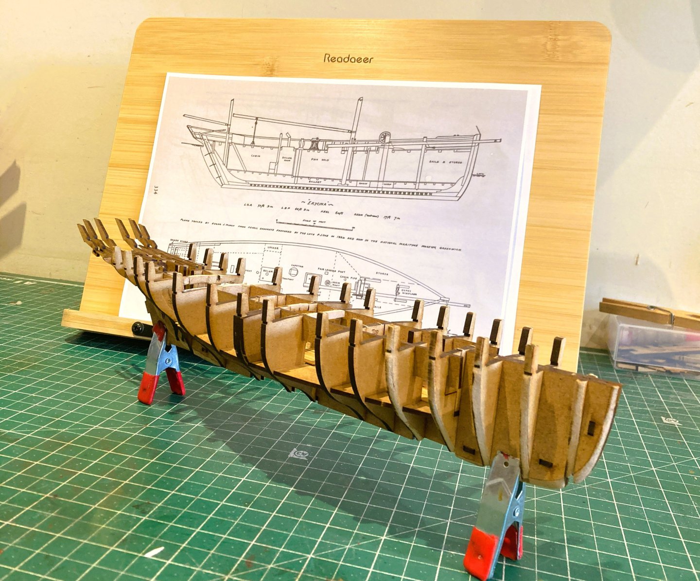
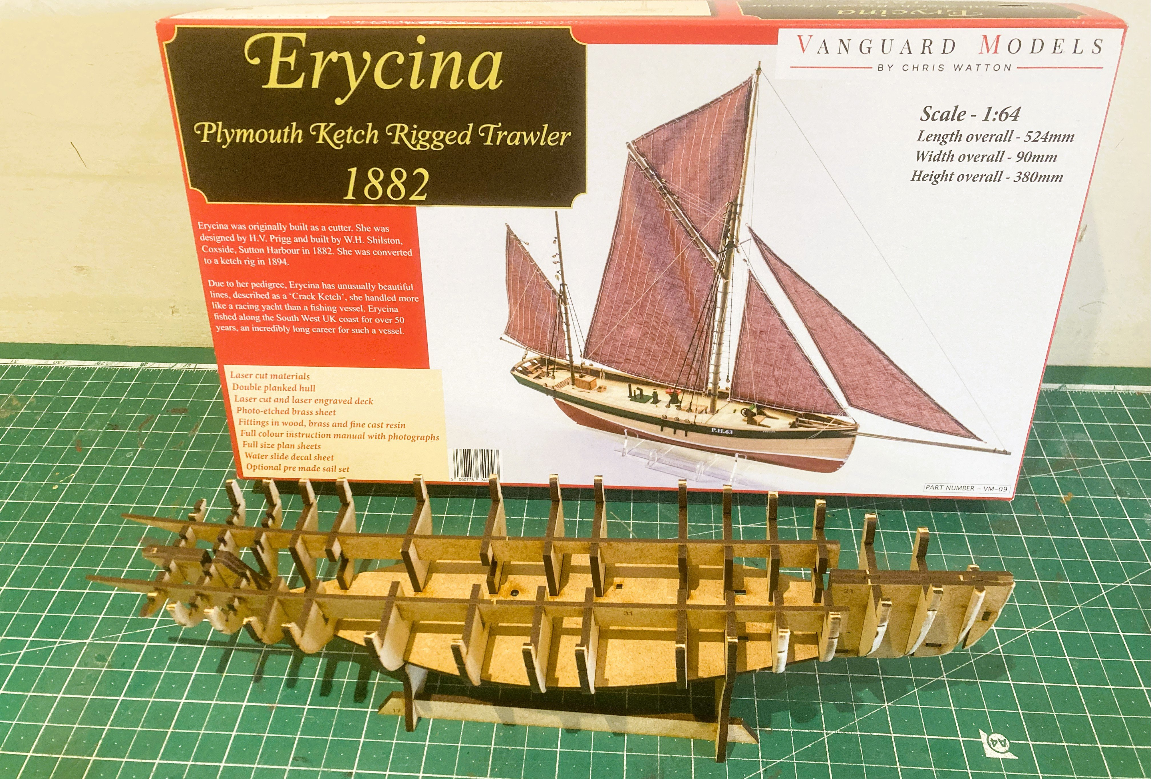
Erycina - Ketch rigged Plymouth Trawler 1882. I’ve had this kit for a while, and with nothing specific in the immediate offing it will give me hopefully a no stress easy build of this pretty little fishing vessel to complement my Fifie and Zulu builds. I was attracted to this boat by its sleek lines and interesting sail plan. Given the open deck and Fore and aft rigging it will be fairly easy to clean, and casing will not be required. It is also a model that will fit in a fairly small space. My interest is also piqued given additional detailing for Erycina is provided in the book Sailing Trawlers by Edgar J. March I can see an opportunity to indulge myself with a little off-piste detailing work. On with the show. B.E. 27/08/2025
-
The Jotika/Caldercraft Surprise sadly looks very clunky compared with the finely scaled details of present day Vanguard kits. Chris has done to the established ranges of many long established kit manufacturers, what HMS Warrior did to the Wooden sailing navy. B.E.
-
Thanks Chris, I can now see where the idea of a cill fixed carronade bed came from - Marquardt's drawings in the Frigate Surprise book. This was a bit of a 'surprise ' to me, as the only versions I recalled seeing are the 'inboard' and 'outboard' variants. Presumably you have tested a PolyBak structure is sufficiently robust to stand the odd inadvertent knock? Cheers, B.E.
-
I think she's a winner Chris.👏 Can you expand a little on the Carronade fixings, seems to be a bracket pinned thro' the cill, I'm not familiar with that arrangement. B.E.
-
Great planking job David, well done.👍 B.E.
-
I note that Boudriot does not show Lodging knees in his Seventy-four gun ship tomes, as neither do the construction photos of the replica French Frigate L'Hermione. In practical terms they would in any case not be visible on your Surprise kit and it would only be of relevance to kit fiddlers like me who may leave deck sections un-planked. In the case of Surprise I thought you would check it out and I am content to concur.👍 Cheers, B.E.
-
Just a thought Chris, will you be providing the Lodging knees to the deck beams as you did with Indy? B.E.
-
A fine looking model, well done, she is an interesting subject.👍 I always fancied building a Granado especially as there is the AotS book on her by Peter Goodwin. I don't know if the standard of fittings has been improved by Amati, as she is quite an old kit, but I suspect that there are many fittings that could be replaced with Syren and Vanguard versions. B.E.
-
Thankyou so much for your generous comments, and also to those who have shown interest and ‘liked’ my stuff. It is very satisfying to know that my ramblings and musings have been of some help to my fellow modellers. Only one question remains…. 8199 Where am I going to put this fine addition to my Vanguard collection. 5504a For the present she will remain in my office beneath her protective cover. Thank you Chris for providing the makings. B.E. 22/08/2025


- 332 replies
-
- 14
-
-
- Harpy
- Vanguard Models
- (and 1 more)
-
A few things to enjoy from the bow image. Look at the subtle curve of the hull form. The elegance of the headworks, and graceful sweep of the main Rail. The provision of double seats of ease. The hinged bracket for the Boomkins in the False rail. The cills around the gunports. A fine figure for the head. and knowing that behind the bow the space is properly formed allowing the detailing of mangers and Bowsprit stop. The Maturin figure, provides the interesting task of getting that subtle patina to the cello surface. Tasty stuff indeed Chris.👌 B.E.
-
Post 107 Completion photos part 2 Close-up shots. 5471a 5464a 5466a 5439a 5467a 5469b 5470b 5444a 5457a 5442a 5437a 5434a B.E. 20/08/2025


- 332 replies
-
- 29
-

-
-
- Harpy
- Vanguard Models
- (and 1 more)
-
Post 106 Completion After eight months of fairly concentrated work this project is now complete. This has been an interesting kit to make and one that has taken more time than I had initially imagined. I had a lot of questions in my mind about certain details and fittings etc; for which there is scant information, and which remain unanswered. Even so, Chris has done an excellent job of creating ‘Harpy’ which makes up into a very attractive model with lots of deck interest. A fine addition to the Vanguard range of kits. The completion Photos (part 1) These are the full hull shots that will feature in my usual build Photo book. 5446b The display stand has been completed, I do like keel blocks as part of the support, a design that has featured in several of my models. 5448a 5450a 5461b 5452a 5453b 5458a 5462b 5472a 5474a 5476a 5480a Part 2 will cover the close-up shots. B.E. 20/08/2025


- 332 replies
-
- 22
-
-
-
- Harpy
- Vanguard Models
- (and 1 more)
-
Sadly not Ron. A bit of a time traveller is Bob, think Outlander. 02806 He began his journey as an able seaman serving on a Flower Class Corvette circa 1940. 1388 He was next sighted working as a rigger on a 14 gun sloop of war circa 1776. This was around 2013 in our time. 04570 In 2020 he was to be found serving on the Cutter Alert circa 1777. Bob’s current muster on Harpy is likely to be his last, but you never know with time travellers.🤔 B.E.

.thumb.JPG.3df8366c4f287cba44e4c408c3a003ee.JPG)

- 332 replies
-
- 12
-
-

-
- Harpy
- Vanguard Models
- (and 1 more)


.JPG.f33acb01f3cfa4d6582213d99ee9d9d6.JPG)
