.JPG.ca33079f5815b861e67b9c2cccd37982.JPG)

Blue Ensign
-
Posts
4,564 -
Joined
-
Last visited
Content Type
Profiles
Forums
Gallery
Events
Everything posted by Blue Ensign
-
 Post 92 Pendents of tackles I have re-visited these as the blocks and seizings looked too heavy to my eye, and as they are fitted before the shrouds, need to be attended to now. I unpicked the seizings and re-used the Pendents. This time I used a 2mm diameter thimble from Chuck’s new Resin range. 4798a 4810a It is quite small but matches the size of 5” suggested by David Antscherl in his FFM Book (Vol IV.) The next size up 3mm, looked a tad too large to my eye. I think this range of thimbles will prove very useful for ship modellers. 👍 Gaff and Main Boom This is an opportune time to attach these to the Mainmast, easier before the shrouds are rigged. I used Boxwood parrel beads rather than the shiny black kit versions. 4854a 4855a 4848a These were coloured using Dark oak wood stain. 4843a No rigging for these items but seized together for convenience. I may rig the sheet simply to hold the booms in place. B.E. 21/06/2025
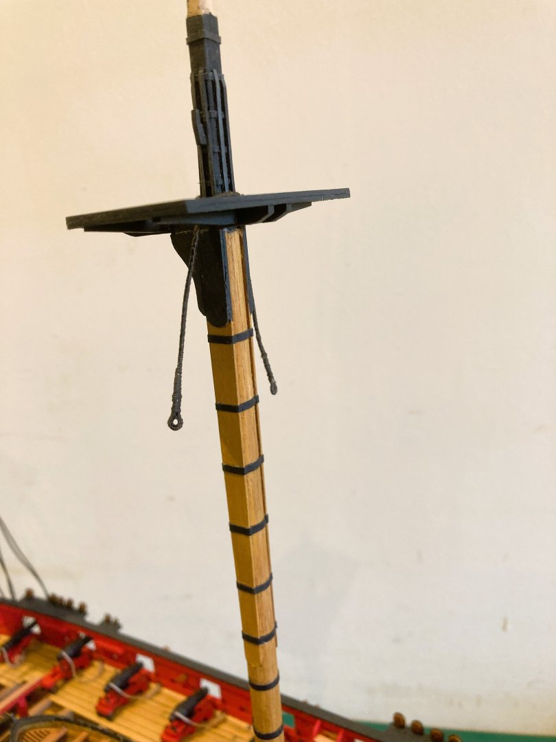


- 332 replies
-
- 15
-

-
- Harpy
- Vanguard Models
- (and 1 more)
-
Cheers Guys, lowered topmasts it is. @ Andy - I wasn't thinking of making up the yards but that is certainly an option, thank you. B.E.
- 332 replies
-
- 1
-
-
- Harpy
- Vanguard Models
- (and 1 more)
-
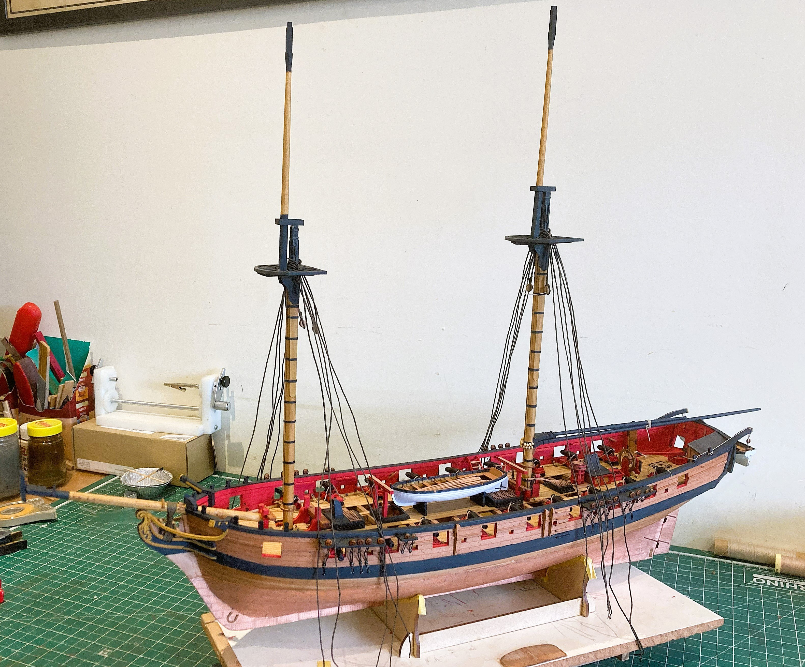
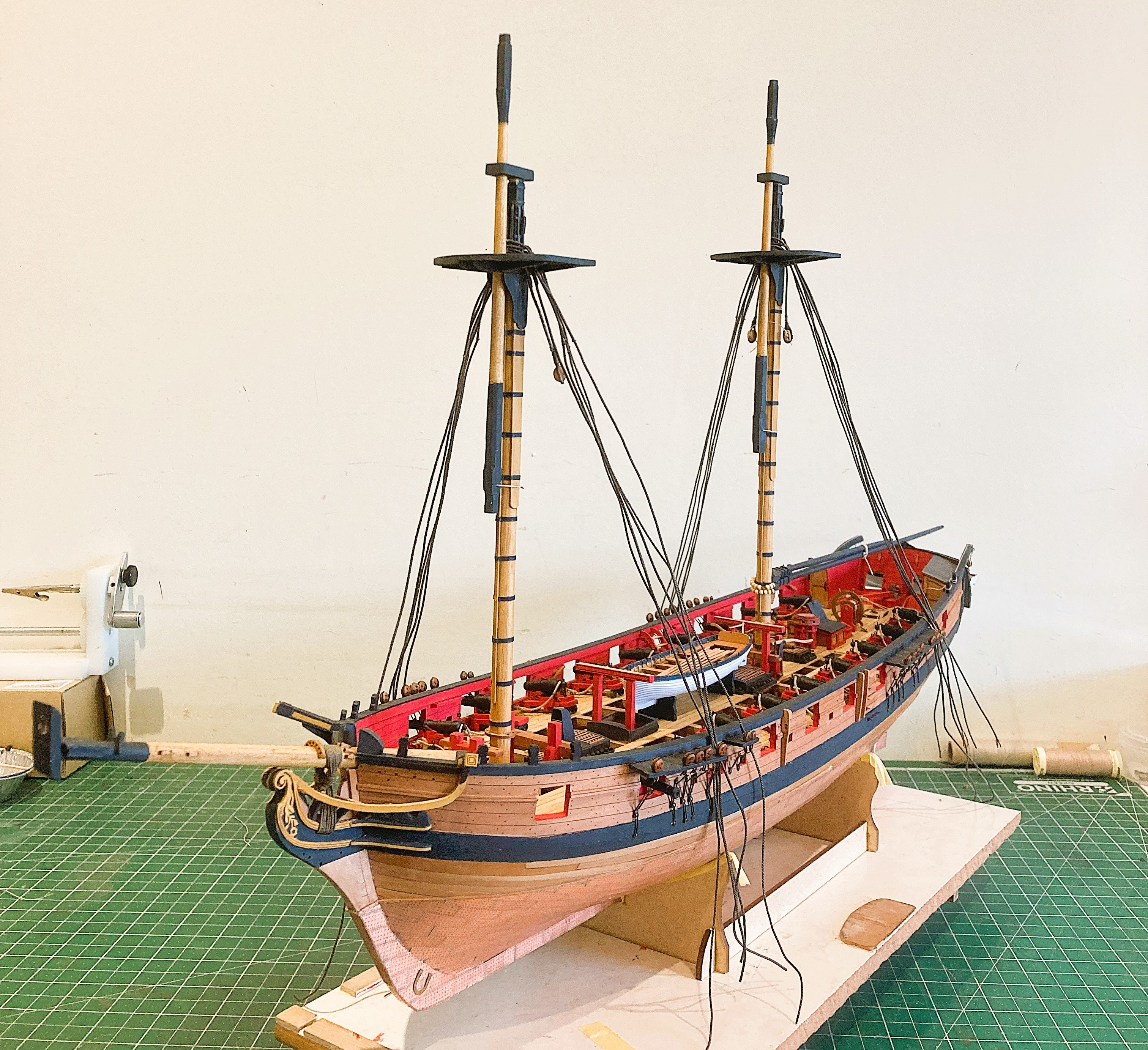
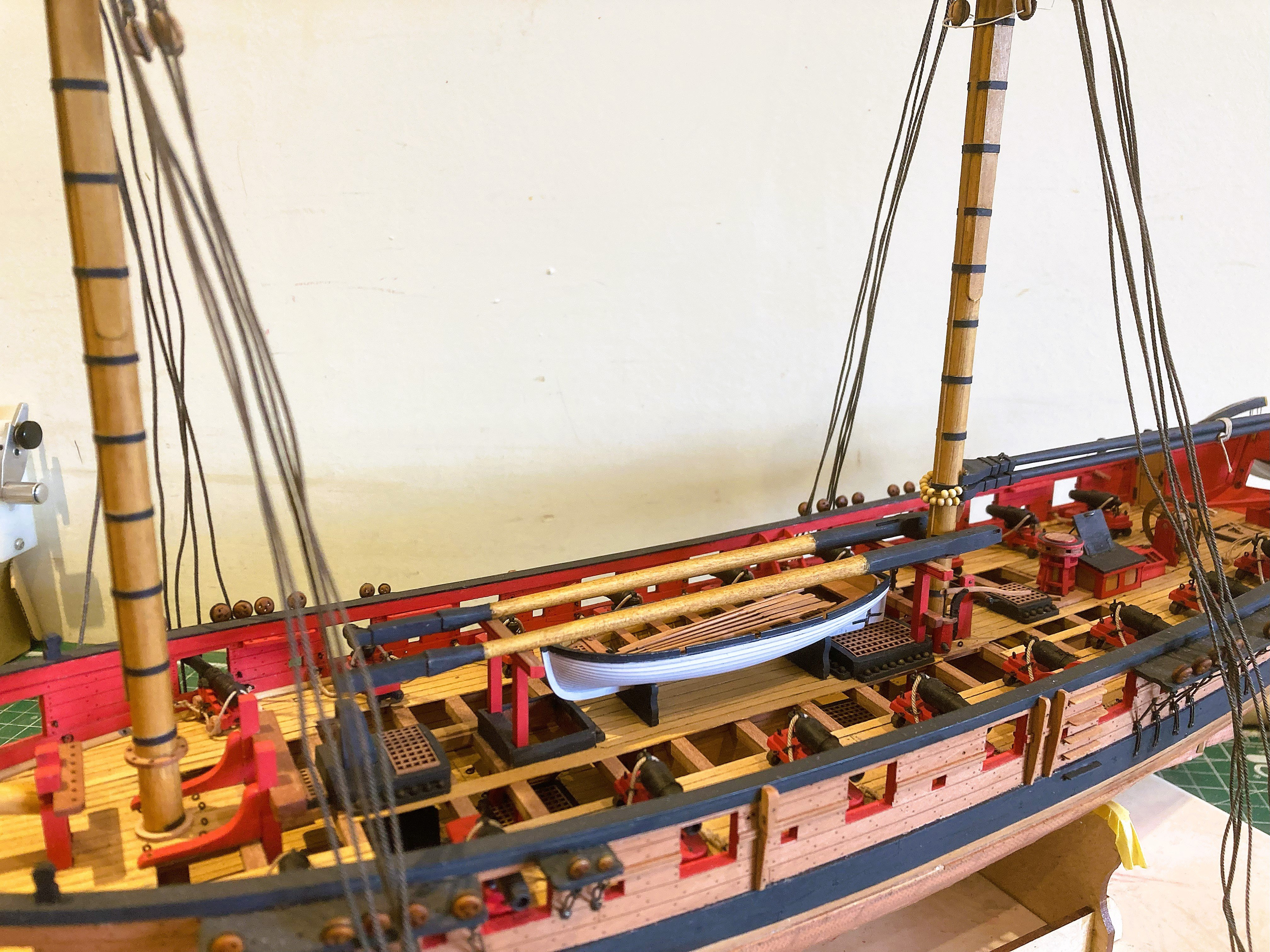
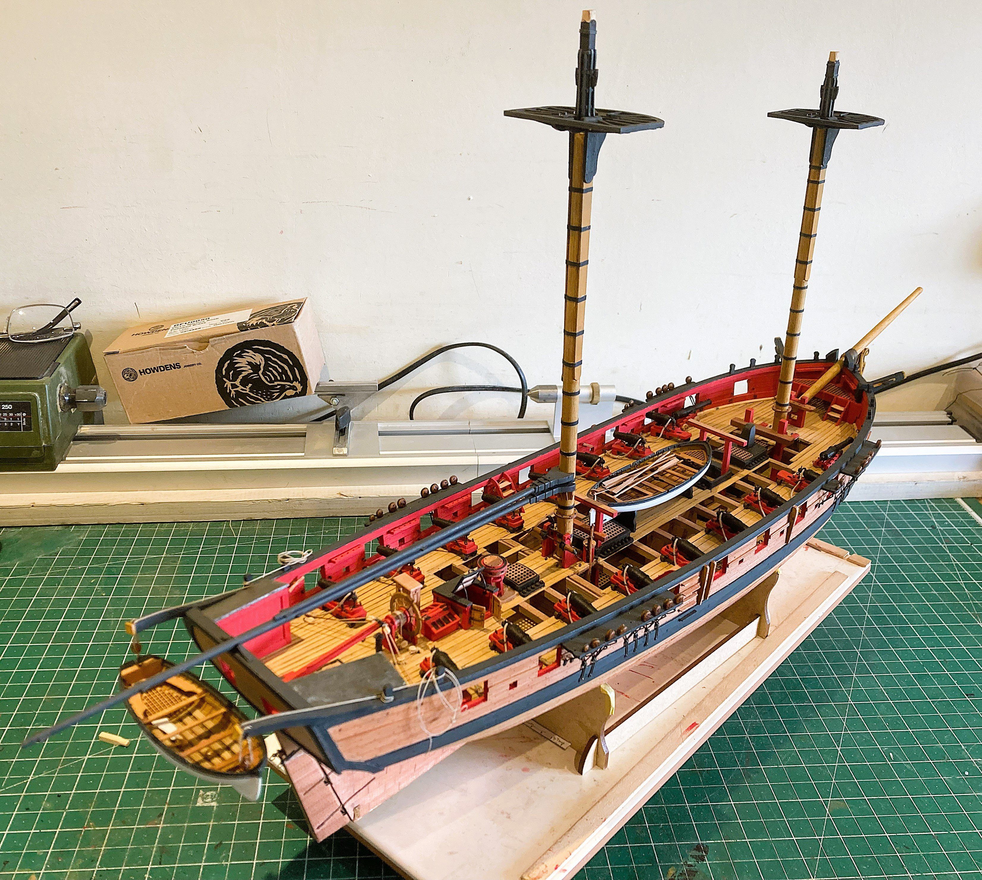
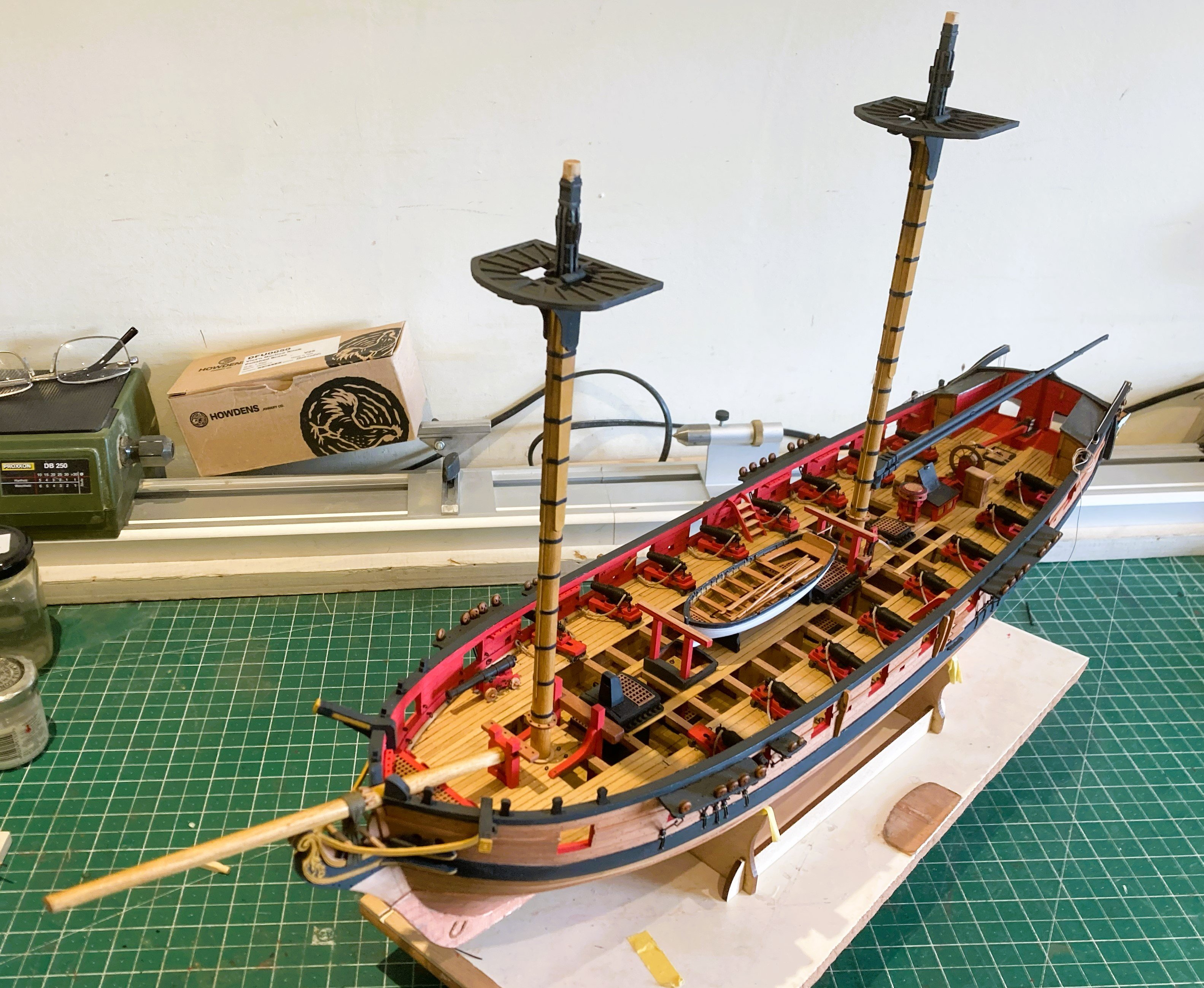
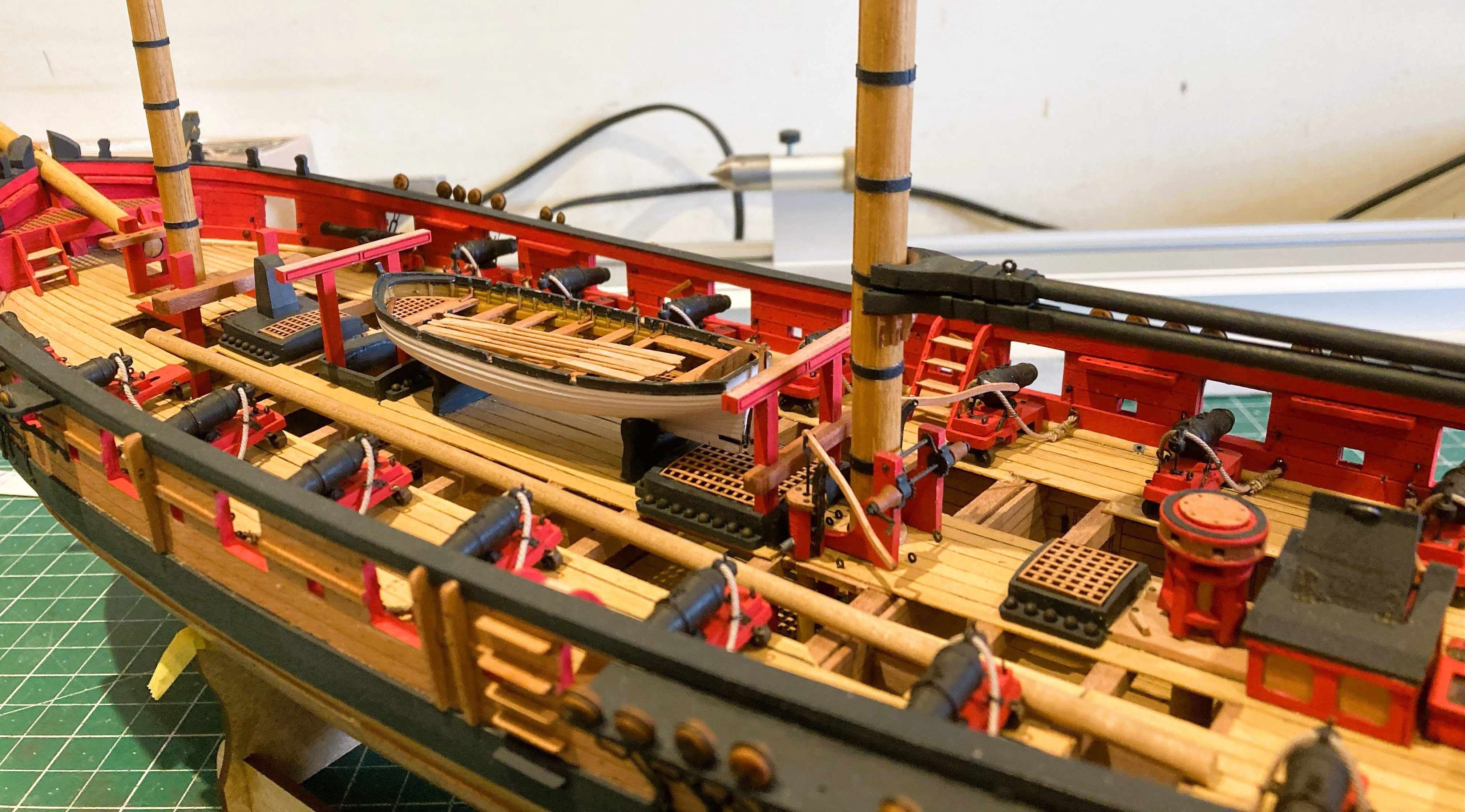
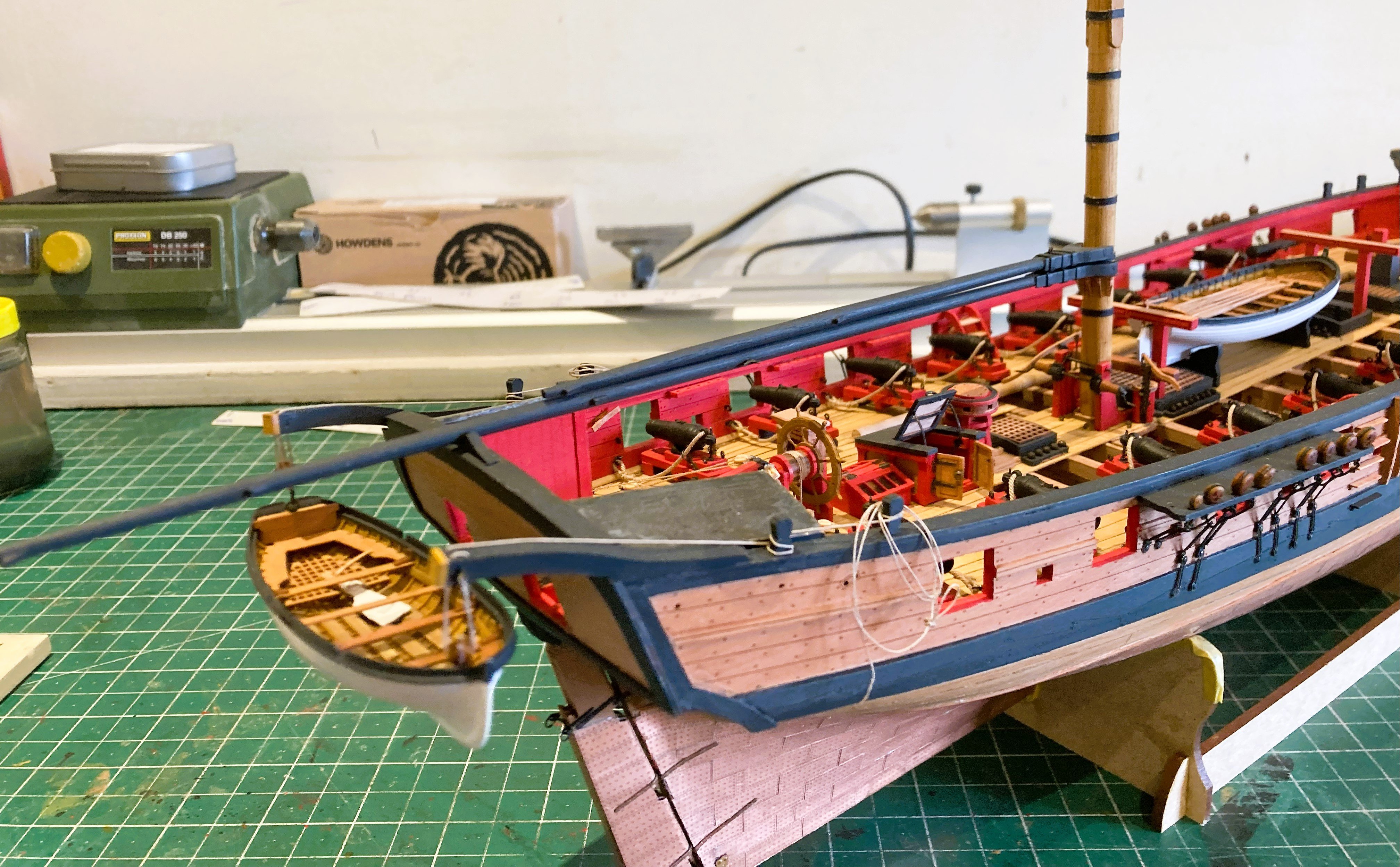
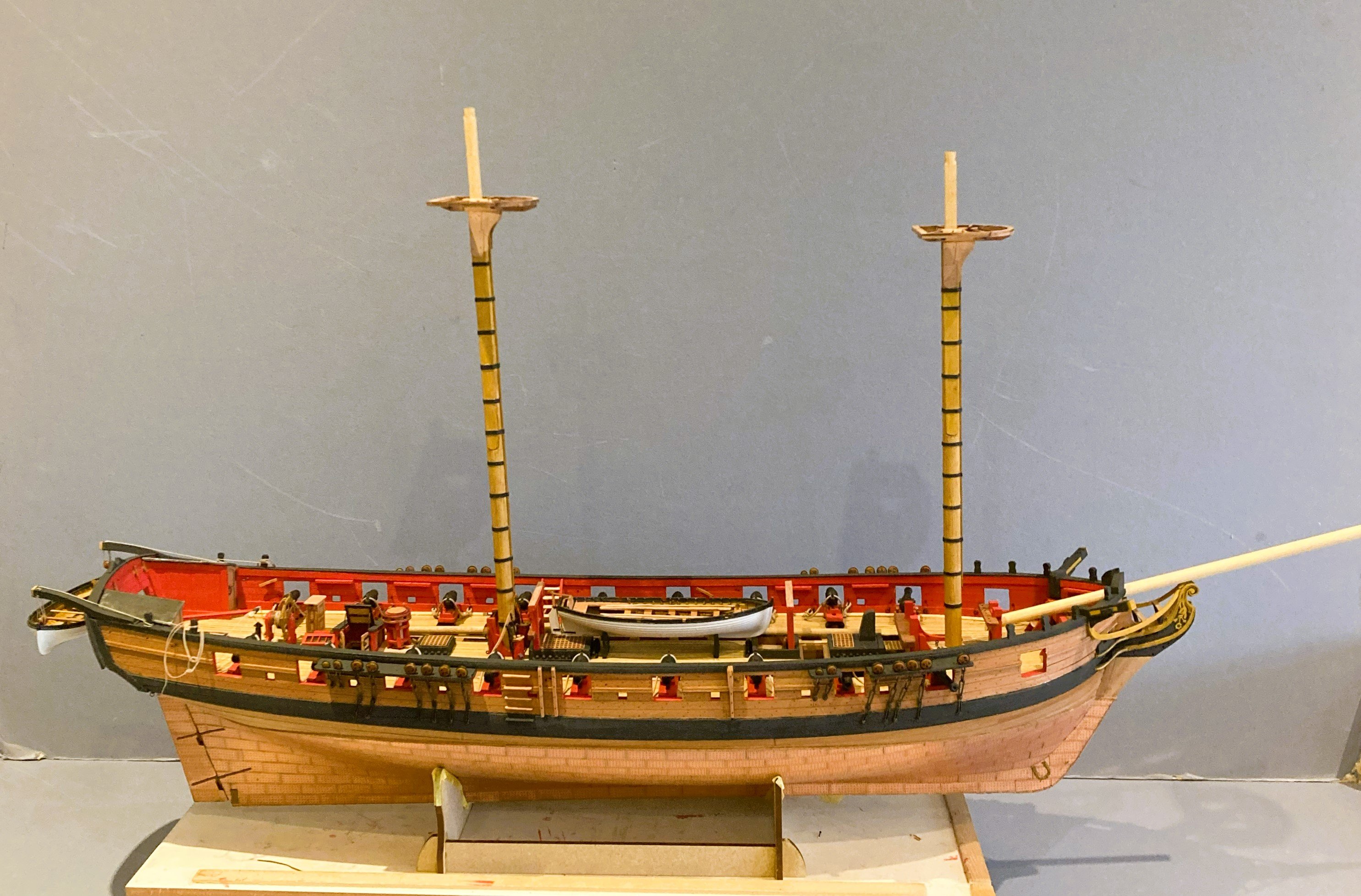
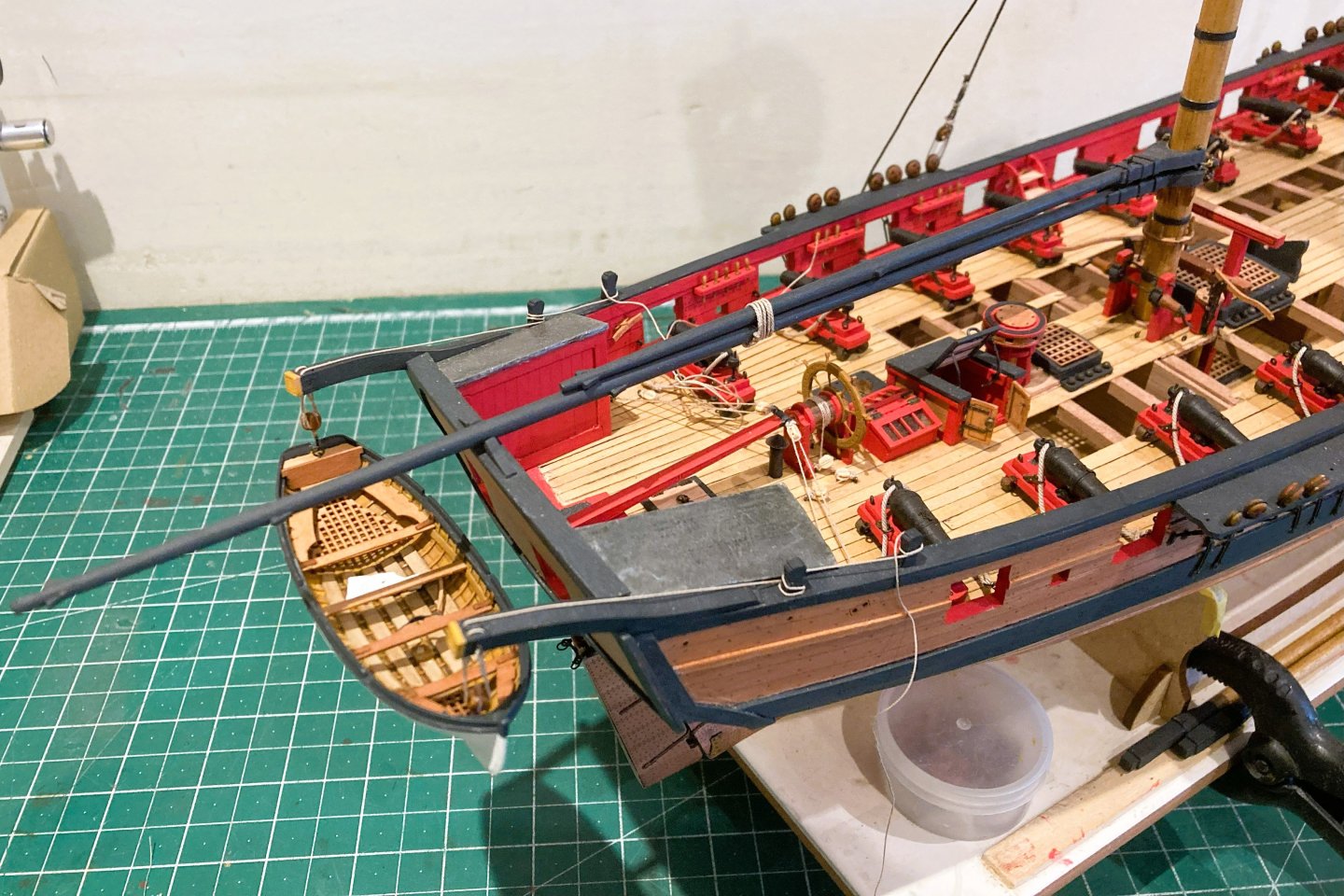
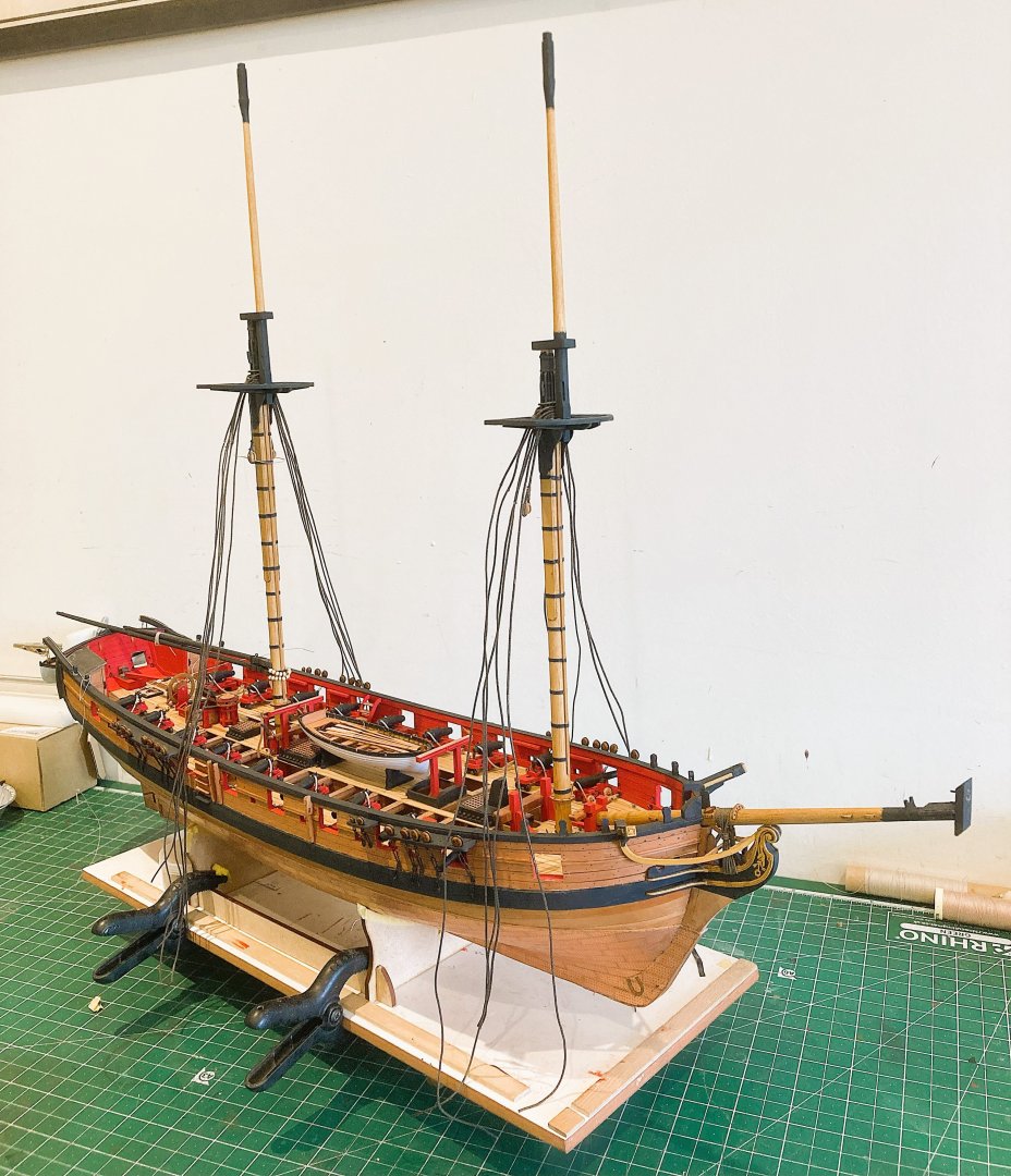
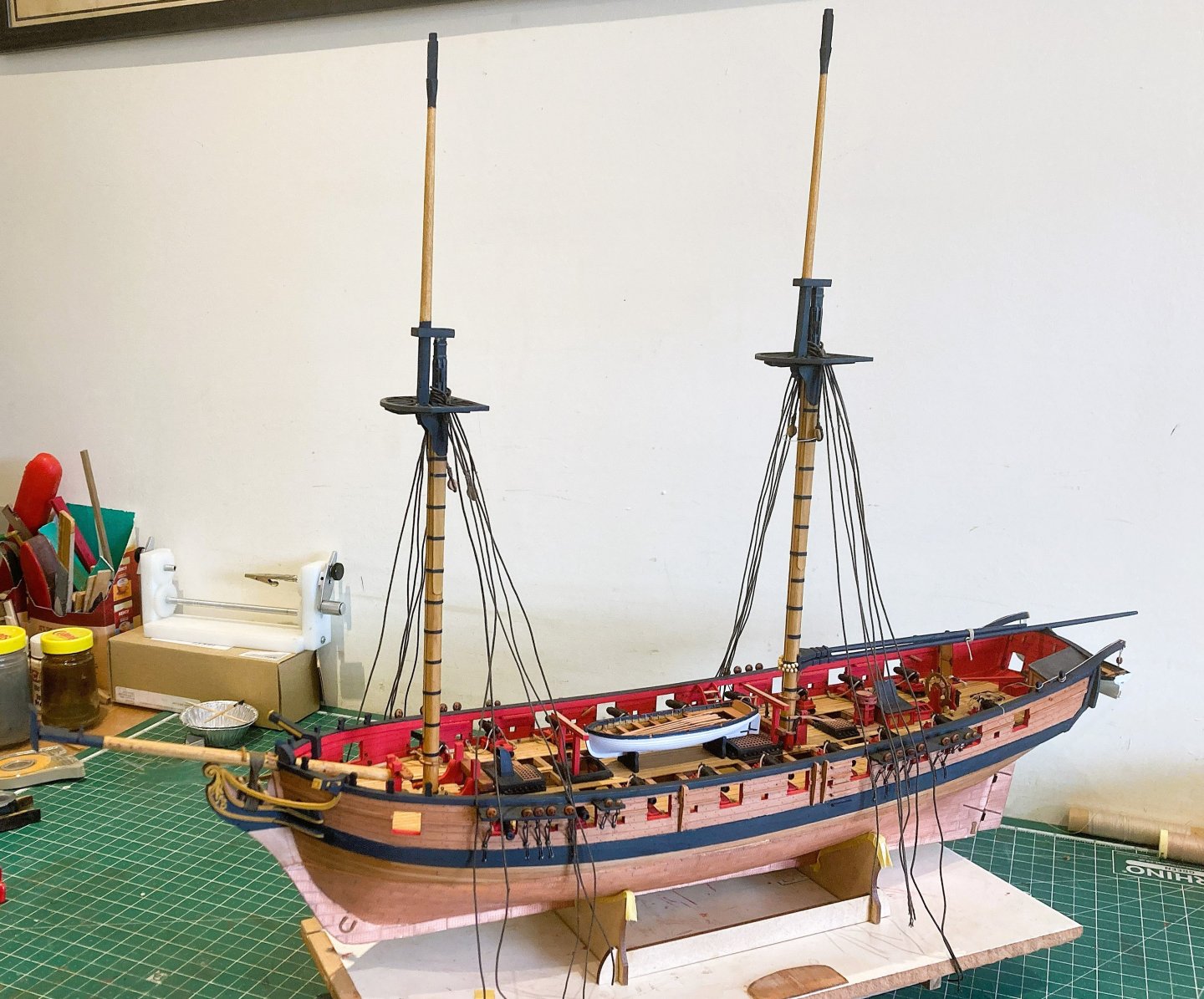
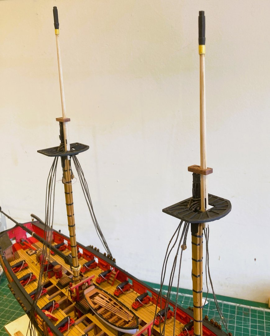
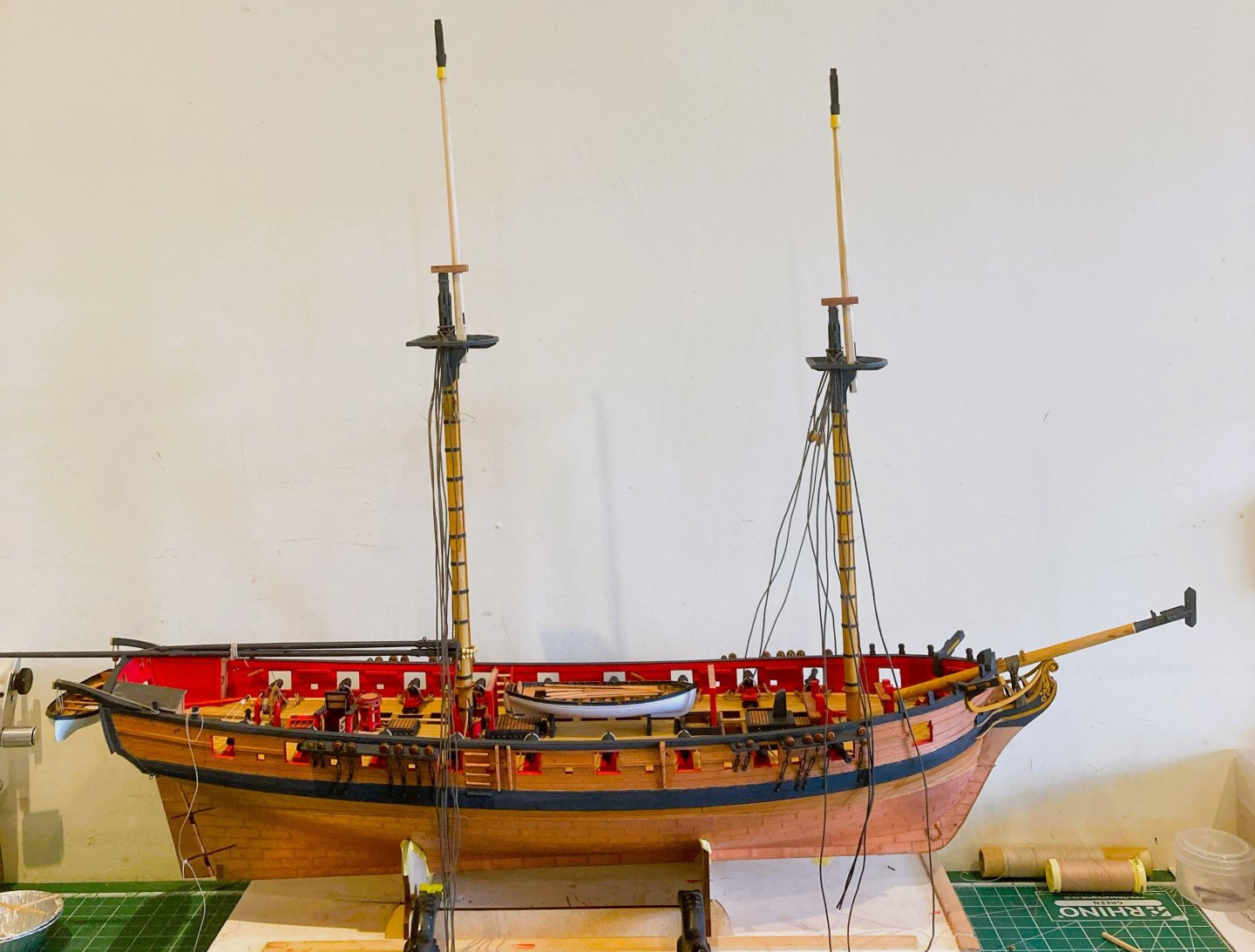
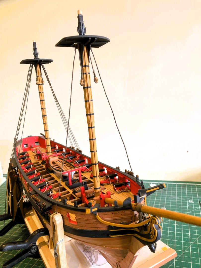
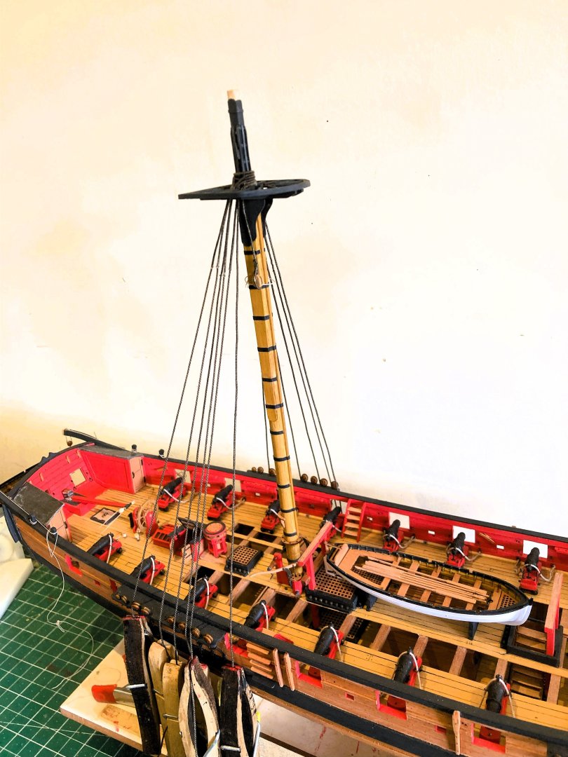
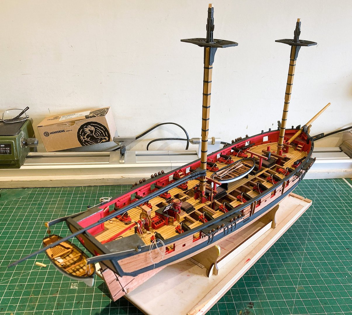
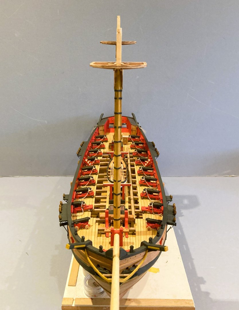
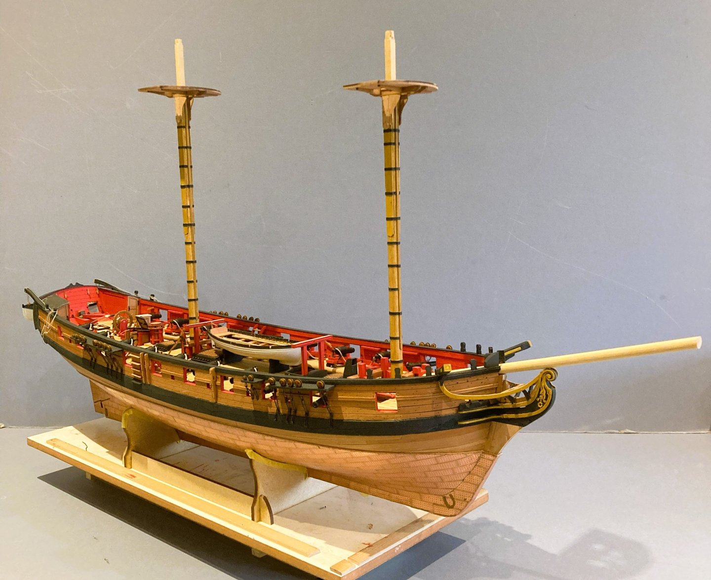
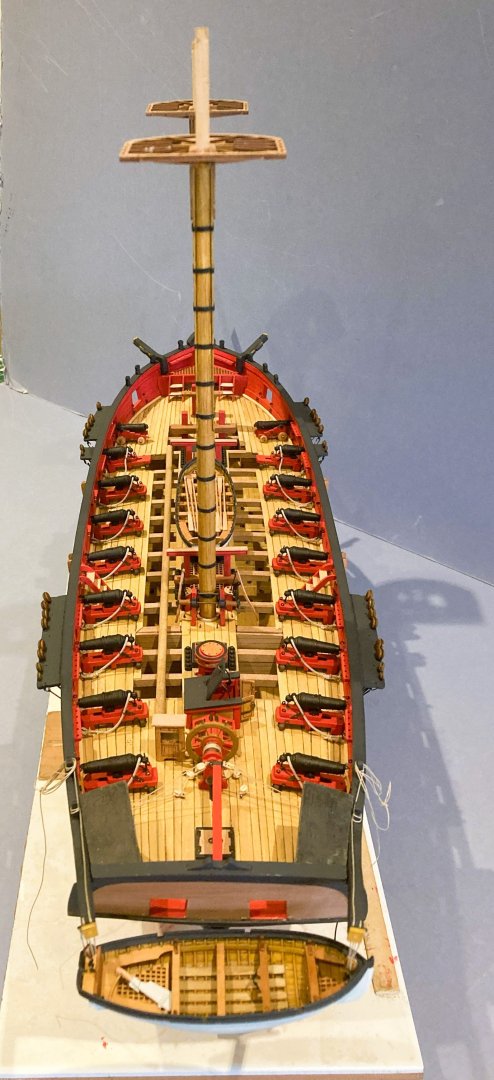
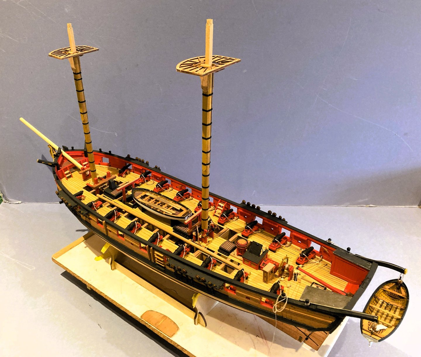
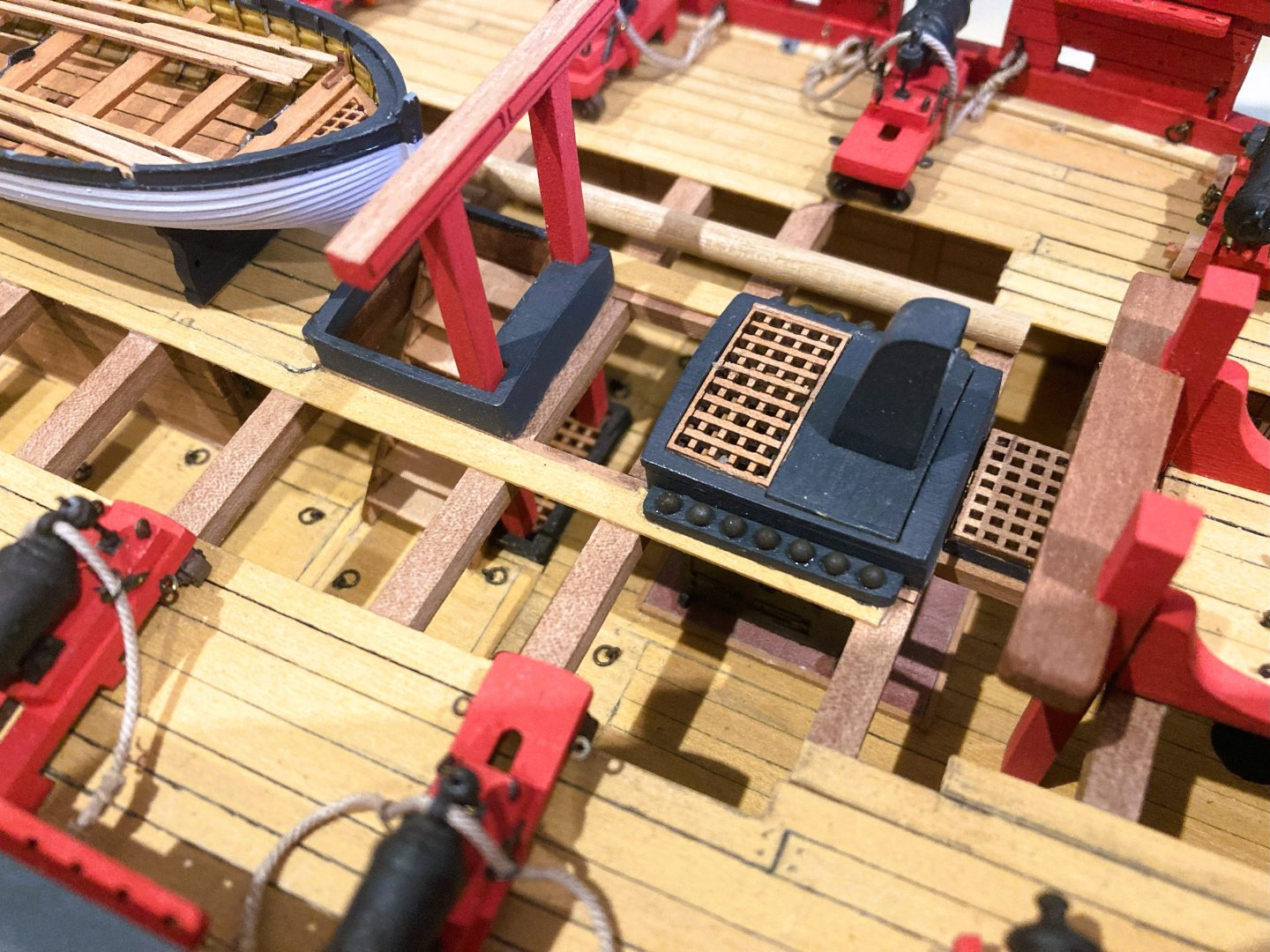
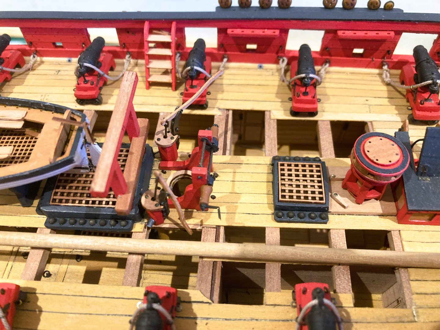
Thank you Glenn for your very kind comment, much appreciated. Post 91 Topmast options I’ve yet to decide how to display the Topmasts, so I’ve been having a play around before the shrouds are fitted. The possibilities are: In the usual raised position. 4749a 4751a .. but this is a non starter, I haven’t room for another tall masted model, but she would look beautiful fully rigged. In a lowered position secured by Top ropes. 4755a 4760a 4756a This has the advantage that it doesn’t increase the height very much. Also provides an interesting rigging arrangement. Secured on the Gallows. 4761 4766a The simplest and obvious location for stowing non fitted Topmasts, but tends to obscure somewhat Chris’s beautiful little cutter, particularly if I decided to store Sweeps on the Gallows. With the Cutter atop the masts on the Gallows 4768a 4770a 4771a a recognised arrangement, which on a practical level clears the deck and displays the cutter to the full extent. I don’t need to decide until the shrouds are fitted, but the lowered Topmast position is the one I’m favouring. B.E. 19/06/2025


- 332 replies
-
- 14
-
-
- Harpy
- Vanguard Models
- (and 1 more)
-
I have now dipped the pins in a dark oak stain which I think tones them better with the model and provides a range of subtle shades. 4811a An original pin is second from the right. (excuse the working detritus) Working on the thimbles now, modifying the Pendents of tackles, I think they will be 👌 Hard to imagine from even a short time ago such fine detail on items so small. Cheers, Chuck. B.E.

- 332 replies
-
- 16
-
-
- Harpy
- Vanguard Models
- (and 1 more)
-
Post 90 Another little packet of wonderments Eights days from order another little packet has arrived from across the pond. Amongst the contents are a supply of Chuck’s new 1:64 scale Resin belay pins. I have been keen to see how these fit Harpy, and you might say I’m highly delighted. 4777a These pins slot into place as if made for the kit, and in an instance have made all other kit provided Belay pins at this scale, obsolete. 4779a These are fitted as supplied without any colouring, but could be darkened if required. On my build they won’t be used for their designed purpose as I’m not rigging her, but they do look good in the racks. 4789a I did do a strength test on the pin and they performed just fine. More likely to pull the rack off the bulwark before the pin breaks. Thanks Chuck, a great job.👍 B.E. 17/06/2025
- 332 replies
-
- 22
-
-
- Harpy
- Vanguard Models
- (and 1 more)
-
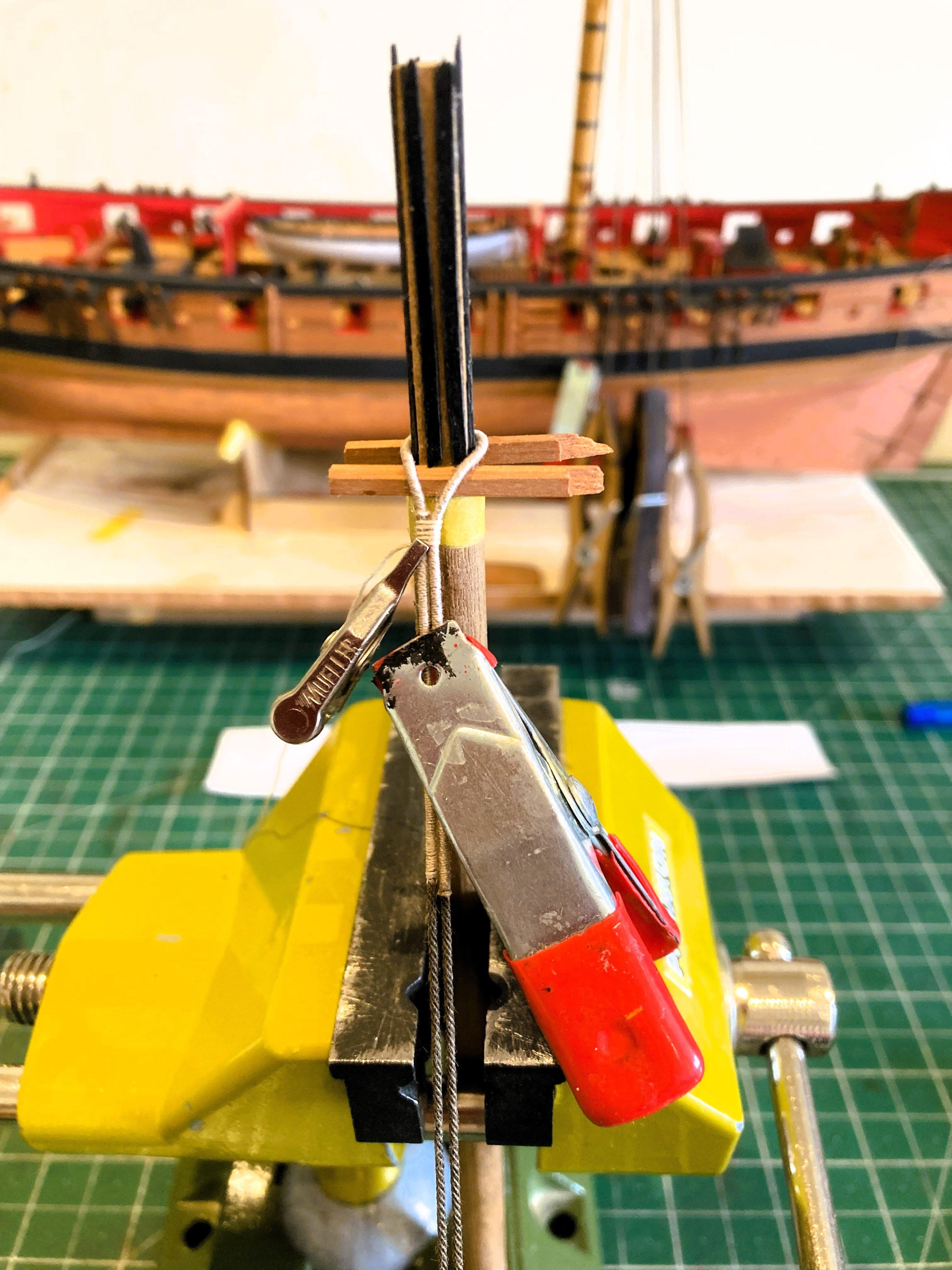
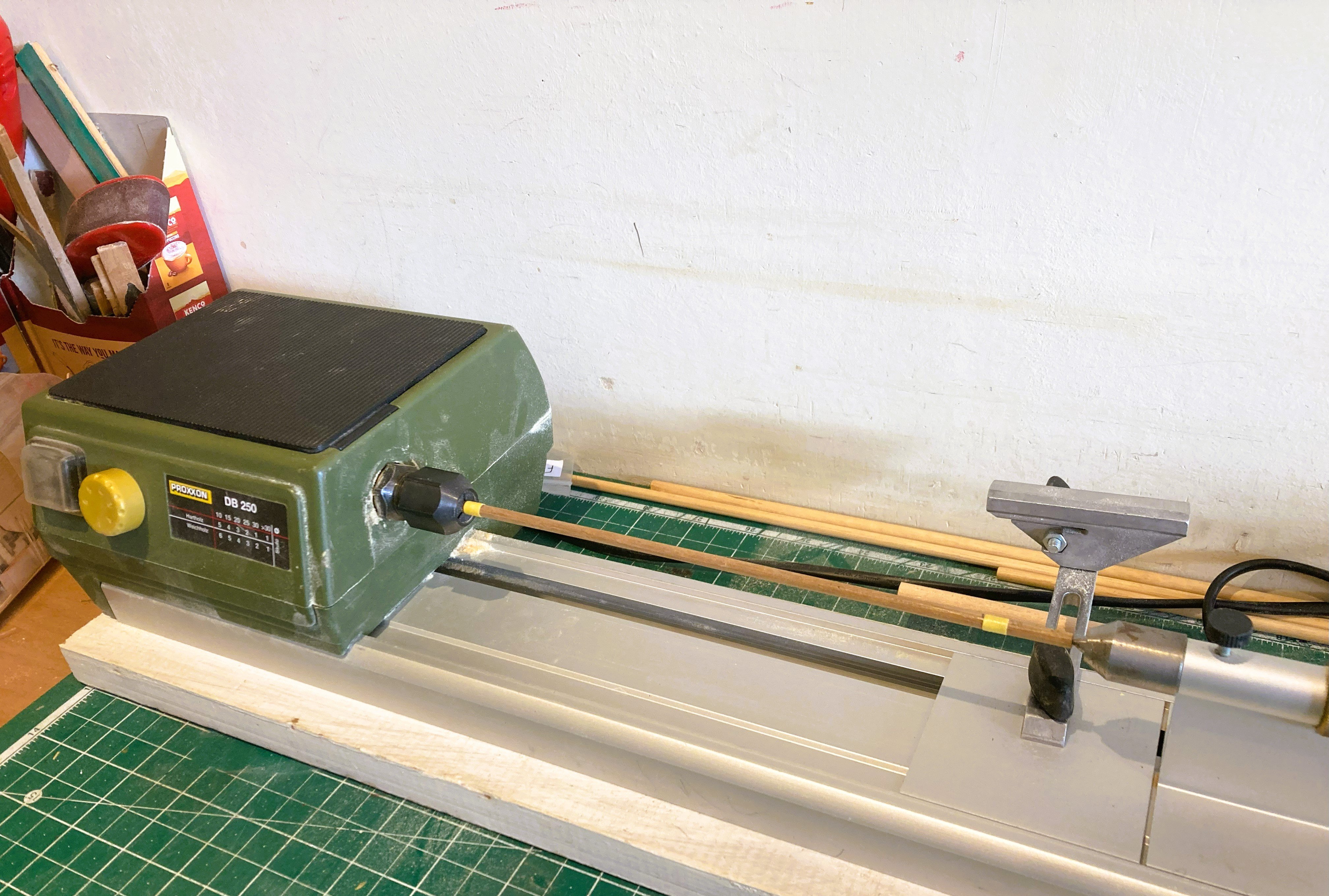
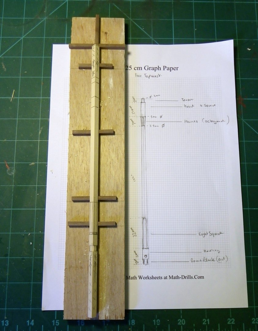
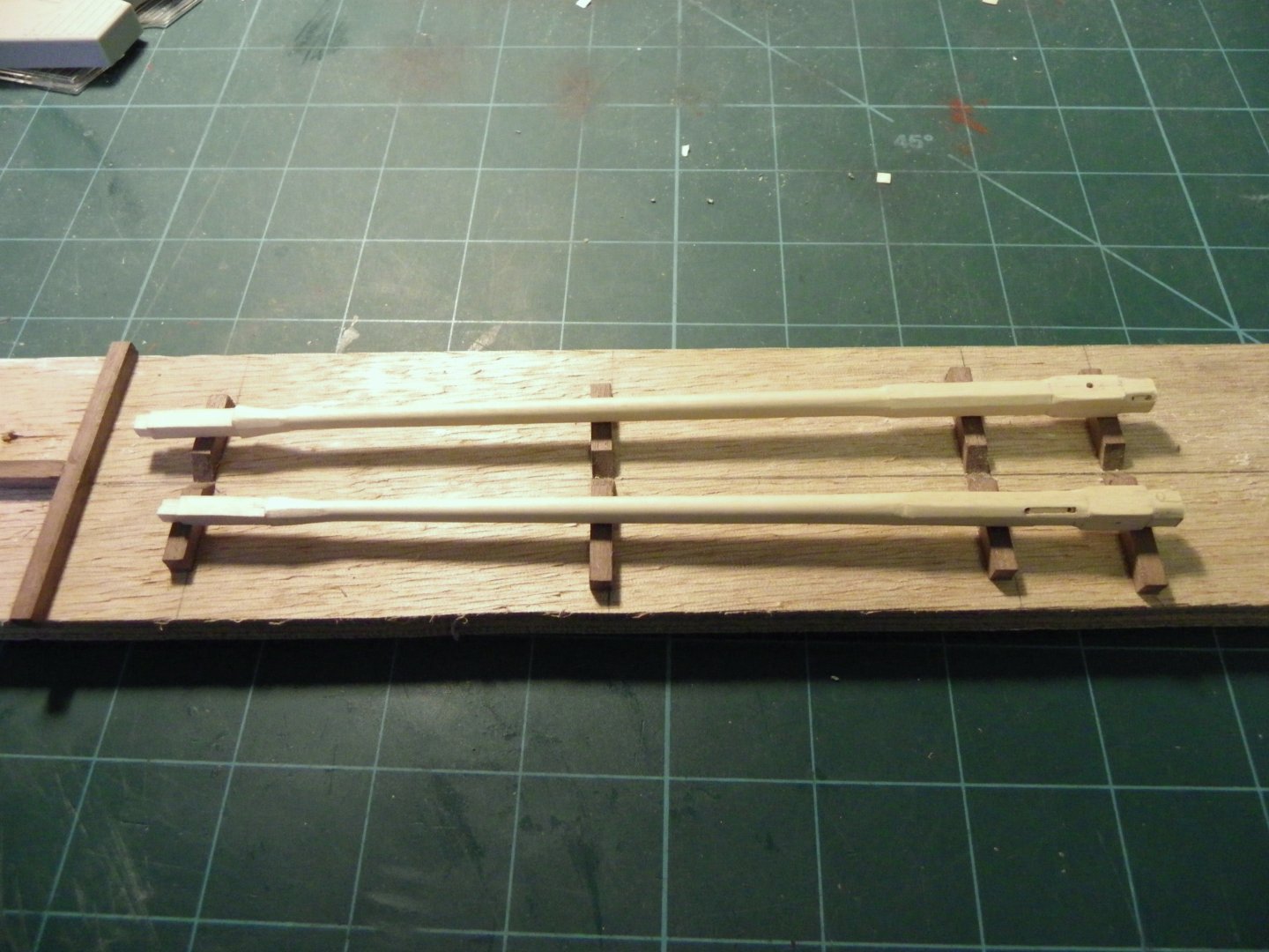
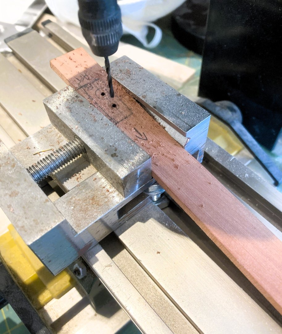
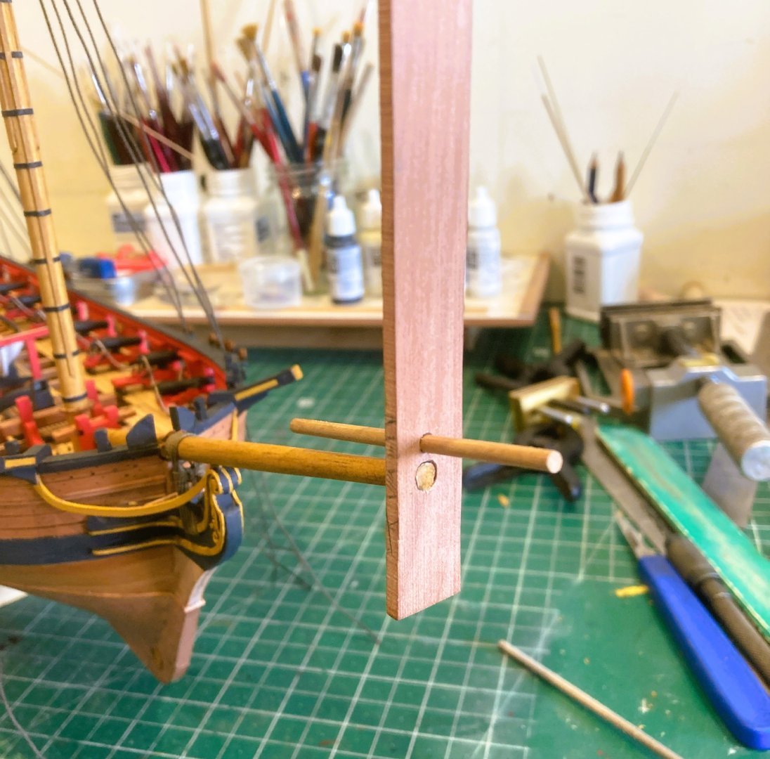
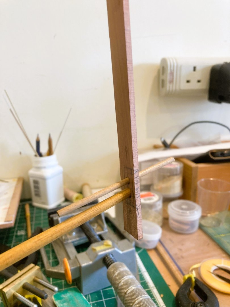
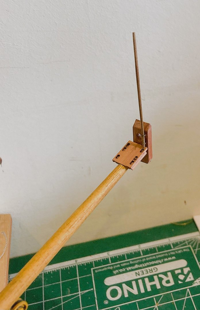
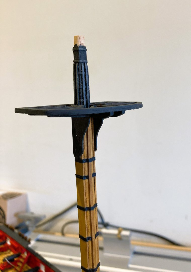
Post 89 Now for the tricky bit -Topmasts The kit version Topmasts are simplified but will still take some careful work using 6mm dowel. There is tapering and creating the flared hounds, and a clean rectangular head. Accurately shaped topmasts are the most complicated masts to make because they have both square and octagonal lower sections, a tapering round mid-section, rising to flared hounds, and a rectangular head. Additionally sheaves set at a diagonal angle are required in the heel. I do happen to have a couple of topmasts I made earlier during the course of my Pegasus build. These were made to Steel’s specifications, and again by luck closely match the kit sizes. 007 The Topmast drawn out and prepared for shaping on a ‘V’ cradle. Square stock is used throughout, it is easier to round the section between the lower mast cap and the Topmast hounds, than create the non round sections from dowel. 028 The lower section showing the square and octagonal detail and the Top rope sheaves. 029 The head section detailing the hounds. 025 The completed Topmasts. 4744a 4739a I had to adjust them slightly to fit Harpy, the critical area being the fit between the fid hole created by the crosstrees and trestletrees. In reality the Topmast should slide up through this section using the Topropes. The kit has the Topmasts at the same length for both Fore and Main. This follows the Steel table for a 200 ton Brig. 4740a The masts I have used are based on a 300 ton sloop where the Main Topmast is slightly longer by around 12mm. Harpy is a Brig sloop, and in my version I have gone more Sloop than Brig, based on the vessel weight. 4748a As it happens the Fore Topmast matches the Kit plan drawings. The extension at the bottom is the block below the heel, which has the lower Toprope sheaves. Onwards… B.E. 16/06/2025


- 332 replies
-
- 23
-
-
- Harpy
- Vanguard Models
- (and 1 more)
-
Nicely done Richard.👍 B.E.
-
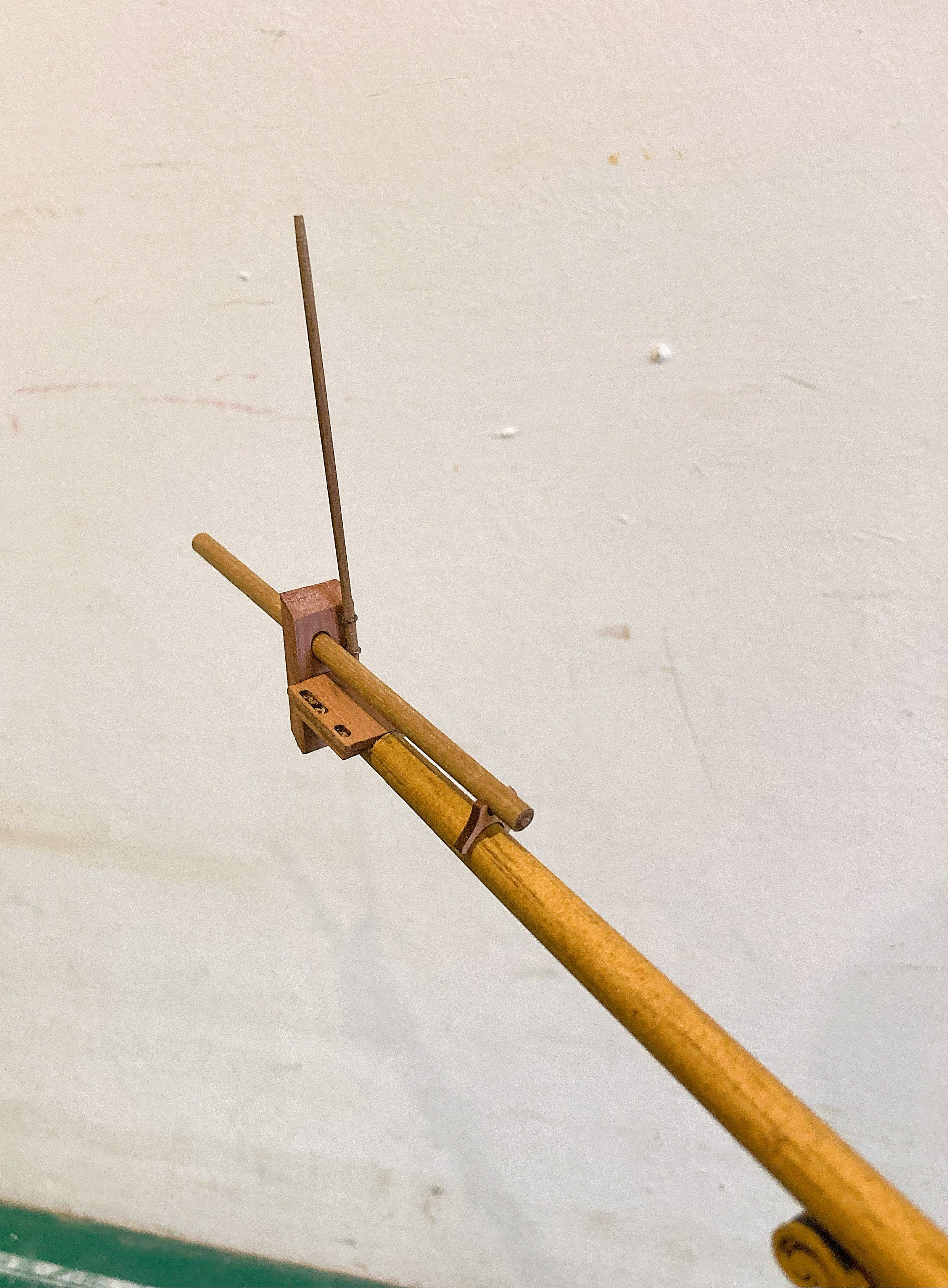
Post 88 Detailing the Bowsprit I originally thought I would not include the Bowsprit Cap on this build because I knew what modifications would be required to address the kit simplification of this part. On my build the cap would be fully exposed without the distraction of rigging. Although still a tricky exercise it is easier to re-make the cap rather than fiddle with the kit part. The real thing is angled top and bottom to match the Bowsprit stive, and holes cut at an angle to the cap which should be vertical to the waterline. The holes are slightly offset to port to accommodate a Jackstaff on the starbaord side. The kit dimensions are 19.3mm(L) 8.1mm(B) 4mm(thickness) I worked the replacement using Steel as a guide (300 ton sloop) Procedure. The new cap is cut from spare Pearwood fret. I used a length of 15mm wide strip of 3mm Pear. The finished version worked out at 20mm(L) 9mm(B) 3mm(thick) 4702a The holes are marked using the kit piece as a template. The tricky part is deciding on the angle and holding the piece at that angle for drilling. 4701a I used the mill for the purpose of drilling the initial holes that were then progressed using files, maintaining the angle. 4703a 4707a I had to cut the rebate for the Bees with the Bowsprit in place, not ideal but fairly straightforward. 4729a Here a trial fit of all components. The Bees are provided with the slots for the Topmast stays but lack the Bee blocks that should sit beneath them. I added these using small lengths of 2 x 2.5 Pear strip. 4716a 4731a The extra width of the cap allows for the Jack staff which is made from some 2mm dowel reduced to around 1.3mm ø. Blackened, drilled out brass eyes support the staff. 4717a A check is made to ensure that the cap is vertical before the glue sets. 4726a 4730a Onwards… B.E. 14/06/2025


- 332 replies
-
- 20
-
-
- Harpy
- Vanguard Models
- (and 1 more)
-
Thank you, Nipper, much appreciated, I do enjoy writing up my log which I do on a daily basis, not entirely altruistic I use it as an aide memoire. I’ve jut looked back to see what I did with the Bowsprit Cap on Pegasus, a good few years ago. It is satisfying to think that my write-ups are a help to others. @ Mark – Glad you are finding this stuff of some use. Cheers, B.E.
- 332 replies
-
- 4
-
-
- Harpy
- Vanguard Models
- (and 1 more)
-
Post 87 Lower mast rigging - Part two Fore and Main shrouds I will be using dyed Syren 0.88mmm line for the purpose. 4653a The line lengths are held under tension for a few hours before fitting to take any spring out of them. The shrouds are put over the masthead in pairs starting on the sb side, then working alternate sides. The shrouds are served for the centre section around the masthead and down to the futtocks. The Foremost shroud is usually served overall to counter chafing from the sails. 4679a Once served I attend to the seizing on a dummy masthead and then slip over the real thing. This is much easier than making up the full mast sets off model, and then doing the work with the masts in place. 4682a The shroud is re-dipped in the colouring solution. 4688a When rigging I always work from aft forward so I begin with the Main mast. Fortunately there are an even set of shrouds so on this mast I can avoid the complication of a splice. Fore Mast There are two sets of two and a single spliced shroud that I have fitted over the masthead first. 4684a This foremost shroud, as with the Main shrouds, is served overall. The spliced section needs to be formed first as with the Pendent of tackles. This is a lengthy piece of serving covering 650 mm overall, and as can be seen there is a degree of kink in the line by reason of the serving. 4687a I put this set under weights to even the line out. 4692a 4693a 4694a The shroud sets are all made up; they will now be removed for final fettlin.’ I have been having second thoughts about the Pendents of tackles. I think the 6mm blocks (15”) look a little heavy, and the seizings a little bulky. I have some of Chuck’s new resin thimbles on order, so a replacement set will be made up. B.E. 12/06/2025


- 332 replies
-
- 23
-
-
- Harpy
- Vanguard Models
- (and 1 more)
-
It's the detailing that makes the model, very nice work Chris.👍 B.E.
- 38 replies
-
- 3
-
-

-
- Alert
- Vanguard Models
- (and 1 more)
-
Well done Chuck, order placed. 👍 B.E.
-
Post 86 Lower mast rigging - Part 0ne My approach to rigging. The limited rigging I will apply to this build will be based on Steel tables for a vessel of 18 - 14 guns of 300 -250 tons. The principle rigging will consist of: Pendent of tackles – 7”circ – 15” Single block- 6mm Lower Shrouds - 7”circ – 0.88mm - (5mm Deadeyes) Forestay - 9½” – 1.19mm - 13” Heart. (5mm) Fore Preventer stay - 6” - 0.75mm - 10” heart (4mm) Mainstay - 10” - 1.26mm - 15” Heart (6mm) Main Preventer Stay - 7” - 0.88mm - 10” Heart (4mm) The kit line dimensions are close to this using 1mm line for the shrouds, and 1.3mm line for the stays. The kit indicates use of deadeyes for securing the stays but I have opted for hearts. I begin with the Pendent of tackles, which are omitted from the kit rigging plan, but are an important feature of naval ship rigging. These go over the head before the shrouds are rigged. I covered my approach to making the pendents in my Pegasus build log. They are spliced over the mastheads, and I followed the method described in TFFM book Vol 1V. 4654a 4657a Syren 0.88mm line is served overall with 0.1mm line, I used the kit provided line which is Gütermann Polyester. Steel indicates use of a single block attached to the pendent, but a thimble would also be appropriate, an opportunity perhaps to try out one of Chuck’s new additions to his fittings, a 2mm option would be about right. 4669a 4666a 4674a I used 6mm single blocks, mainly as I had them to hand. 4665a At this time period the pendents extend a little below the Hounds. B.E. 08/06/2025


- 332 replies
-
- 19
-
-
- Harpy
- Vanguard Models
- (and 1 more)
-
Thank you Mark, once the seizing is complete I use a scalpel blade to carefully cut the tube and remove it. Regards, B.E.
-
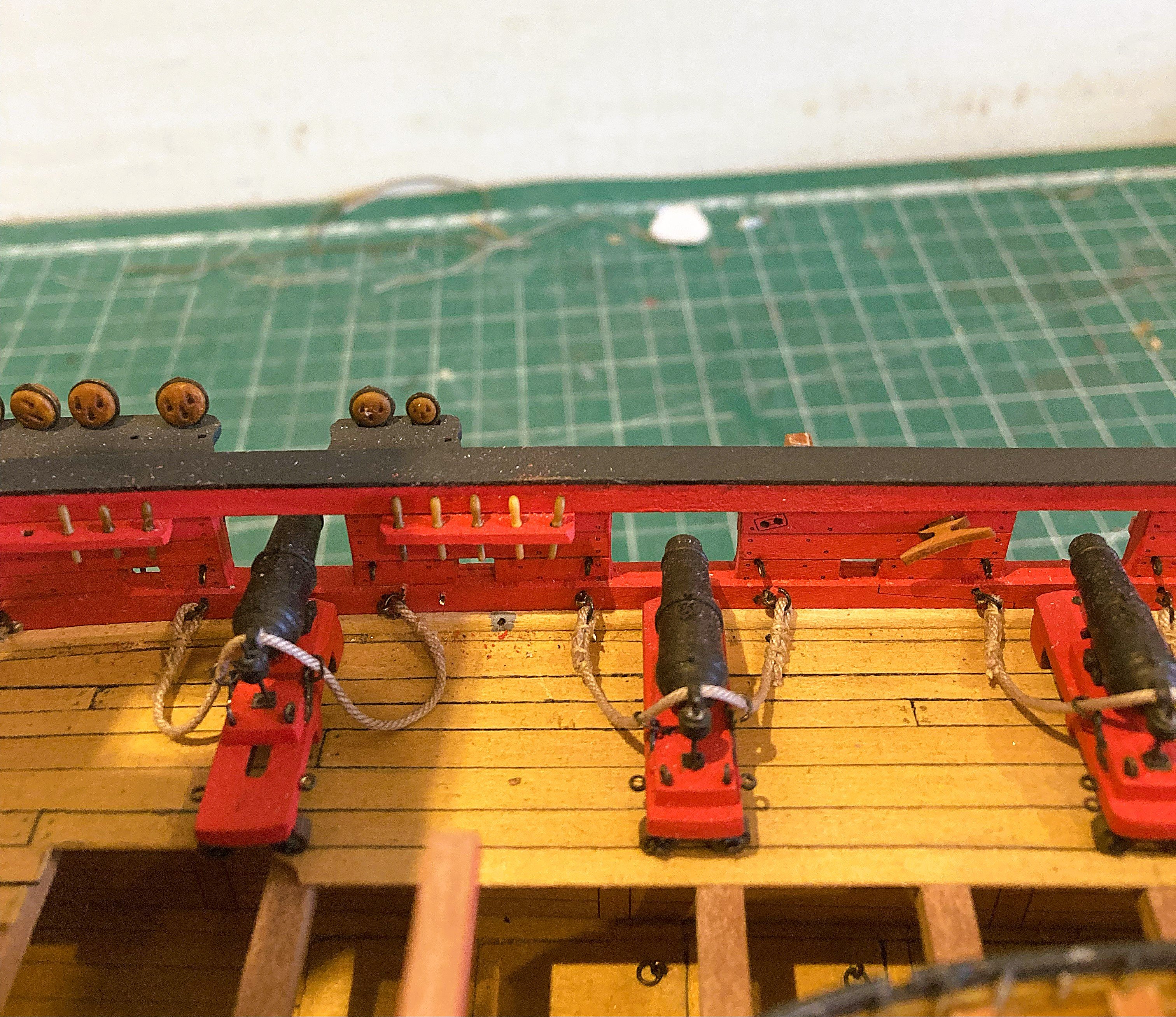
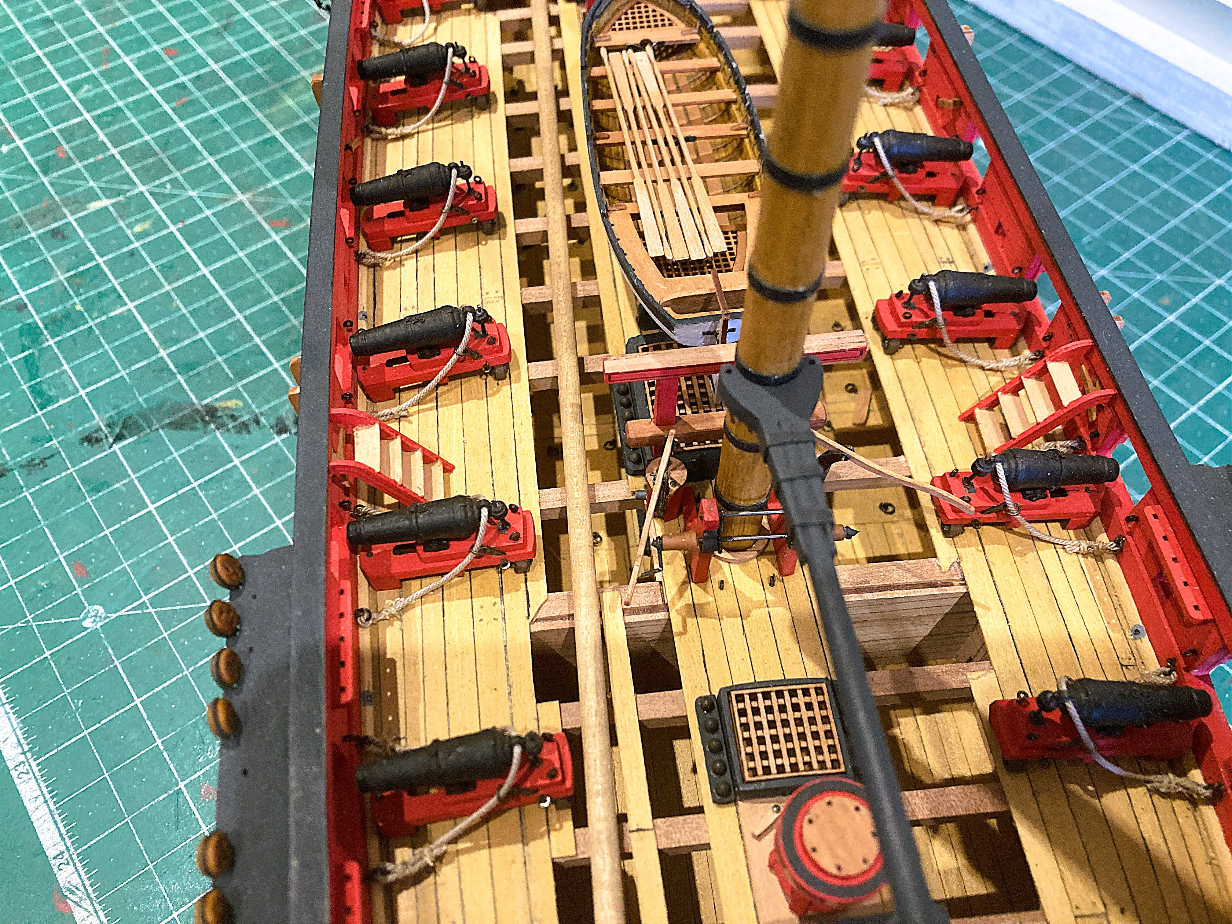
Post 85 A short post about Long Guns Harpy has two Bow chaser six pounders which I have been thinking about how to display. These are the last two items to be fixed to the deck, ideally done before the masting and shroud rigging begins. I had thoughts of lashing the Long guns inboard, parallel to the ports, but I couldn’t quite decide on the lashing approach, so I took the soft option and positioned them run-out. 4638a The breeching rope is 3 x the gun bore length, using 4” circ line – 0.50mm dia at scale. I actually used Syren 0.63mm ø line. I will only be attaching the Breechings, as I did with the Carronades. For those in mind to attach the side tackles:- Tackles 1½” circ line - 0.20mm ø at scale Rigging blocks single 5/6” size -2mm-2.5mm at scale. 4641a I find it useful to use small sections of tubing to secure the breeching line for addition of the seizings. 4649a I used Morope 0.1mm Polyester line for seizing, it is the finest 0.1mm diameter line I have found. 4647a Quite fiddly to seize the breechings on the model, a better job can be done using an off-model jig. The downside is that it can also be fiddly fitting the bulwark ringbolts with other deck fittings in place, and the guns may have to be fitted at an earlier stage of the build. 4650a Onwards…. B.E. 07/06/2025


- 332 replies
-
- 22
-
-
- Harpy
- Vanguard Models
- (and 1 more)
-
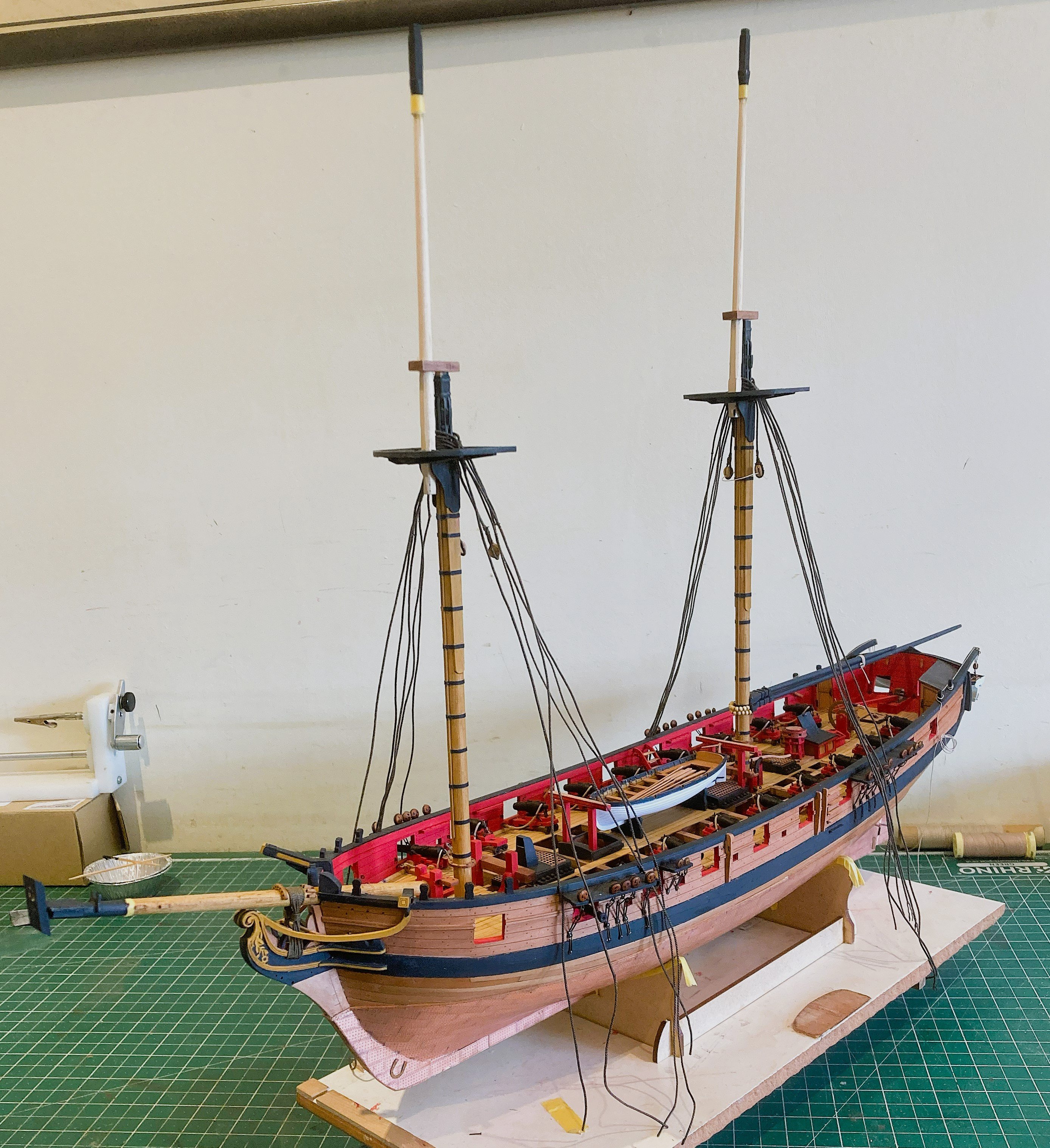
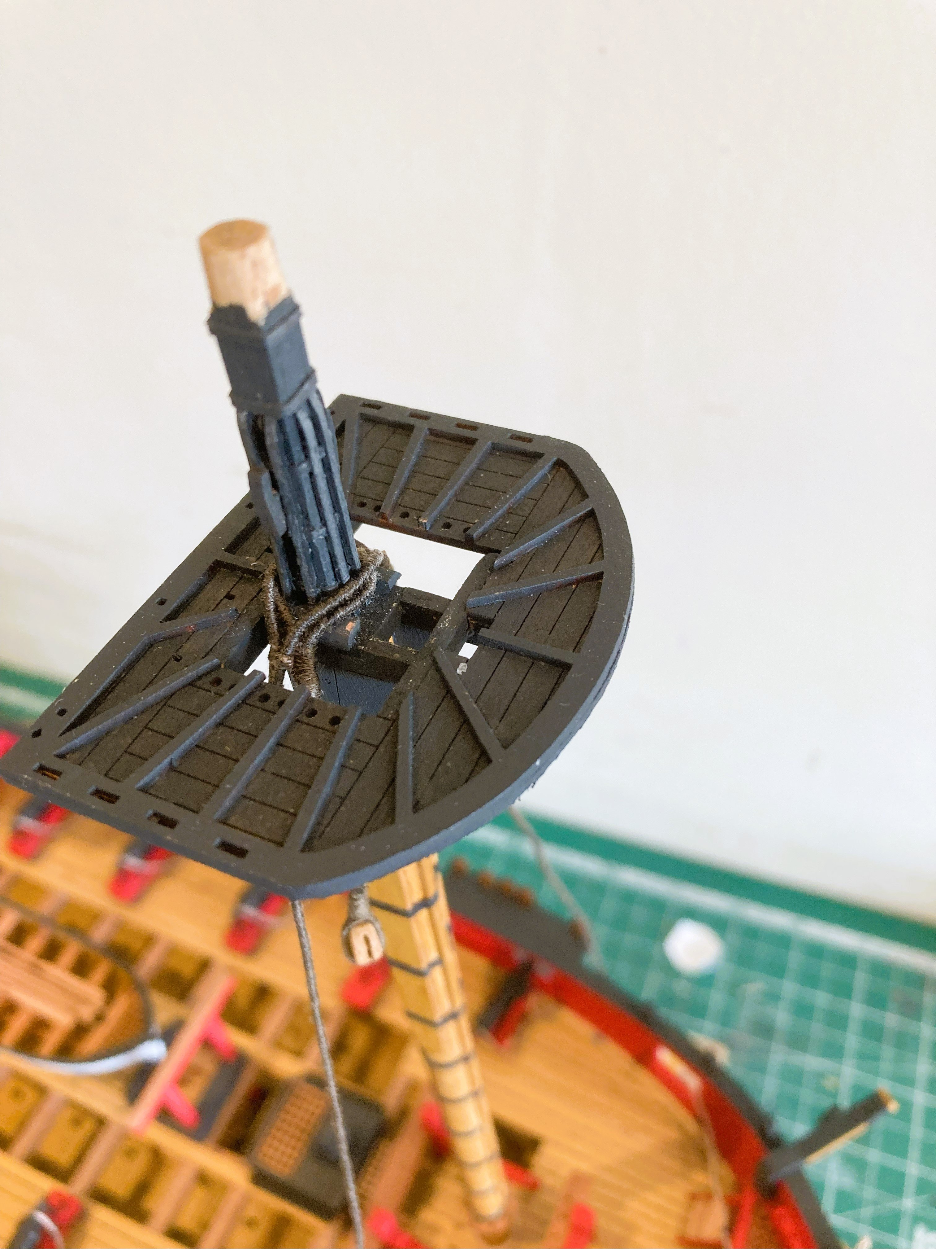
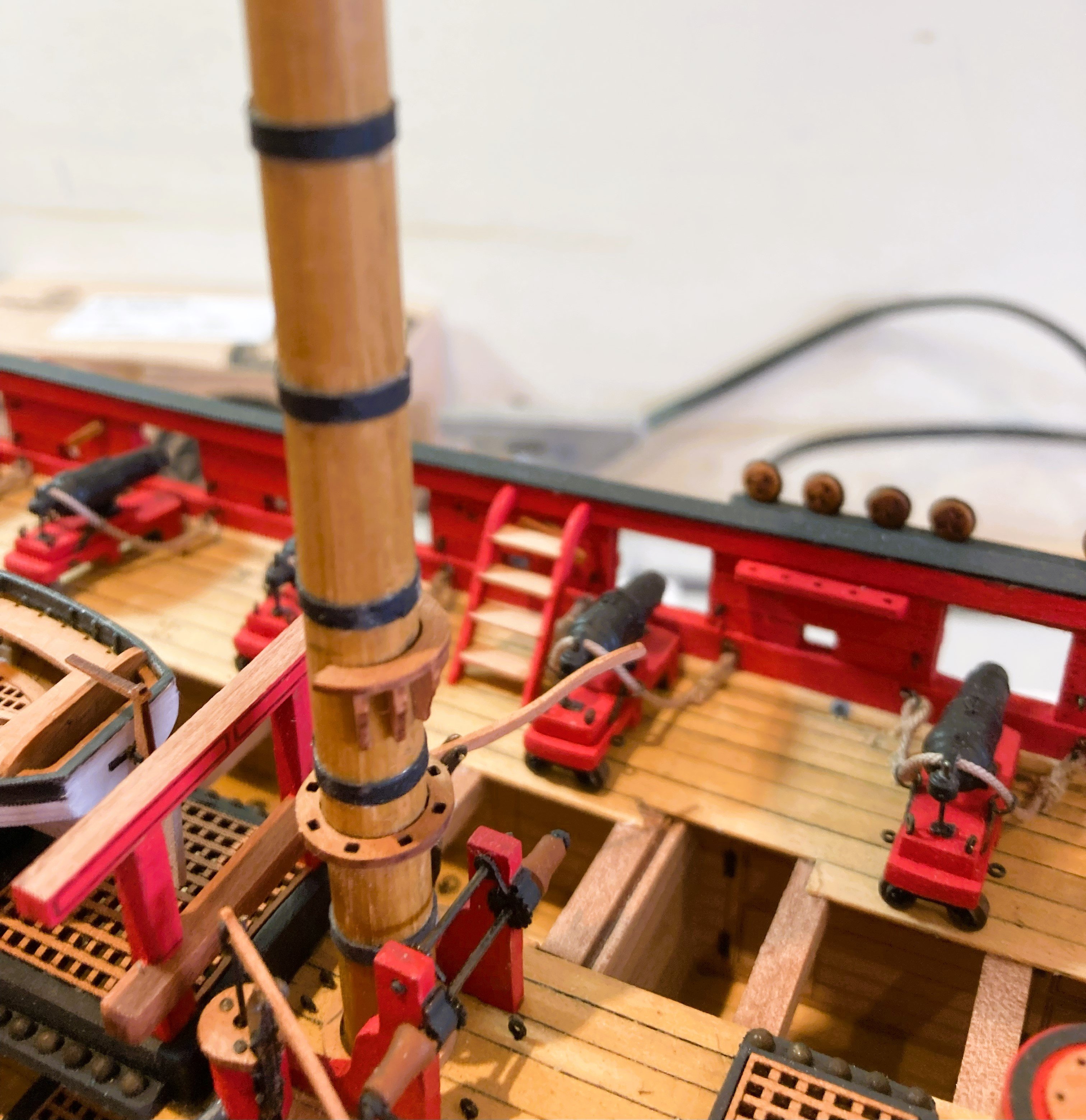
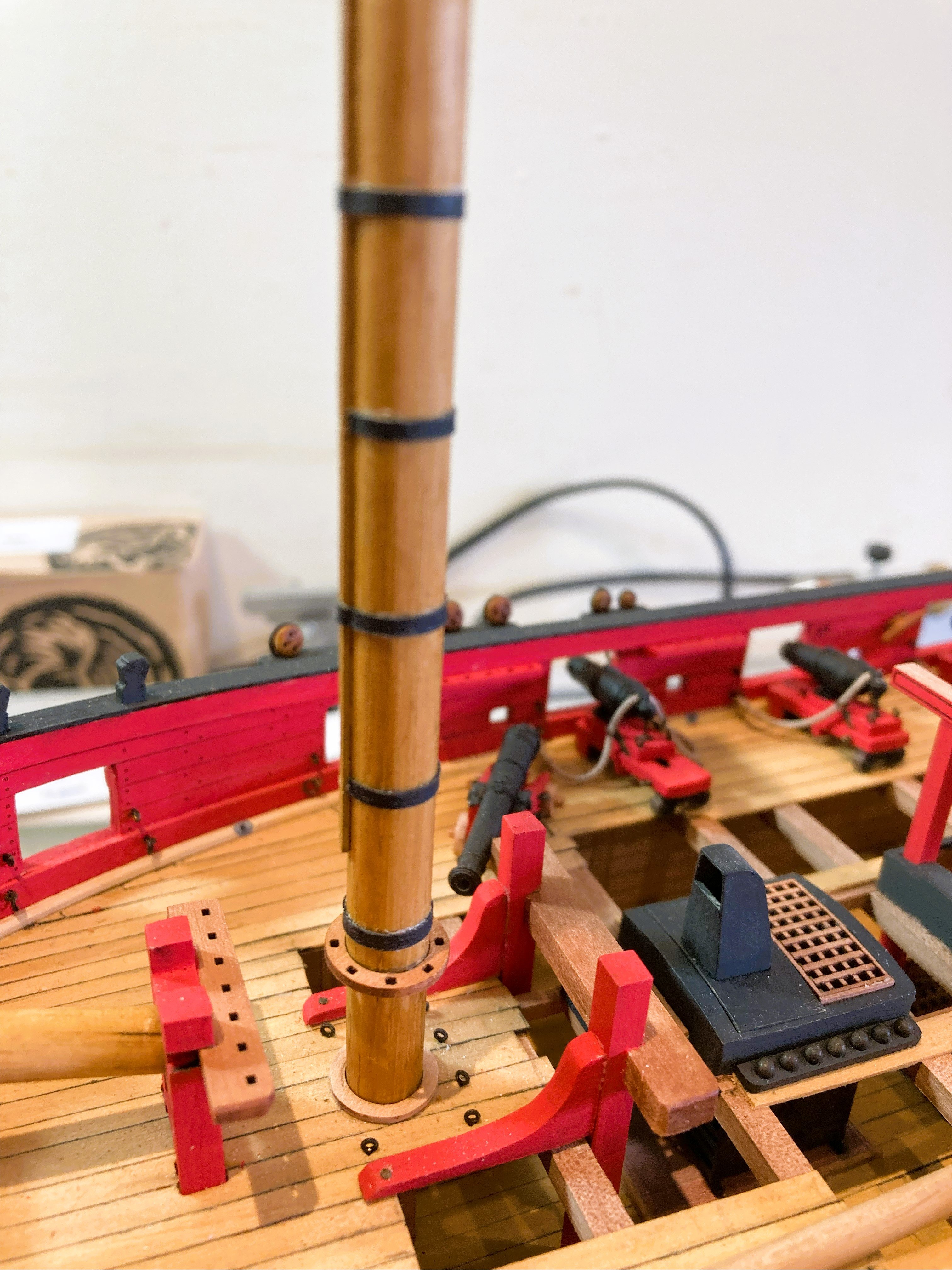
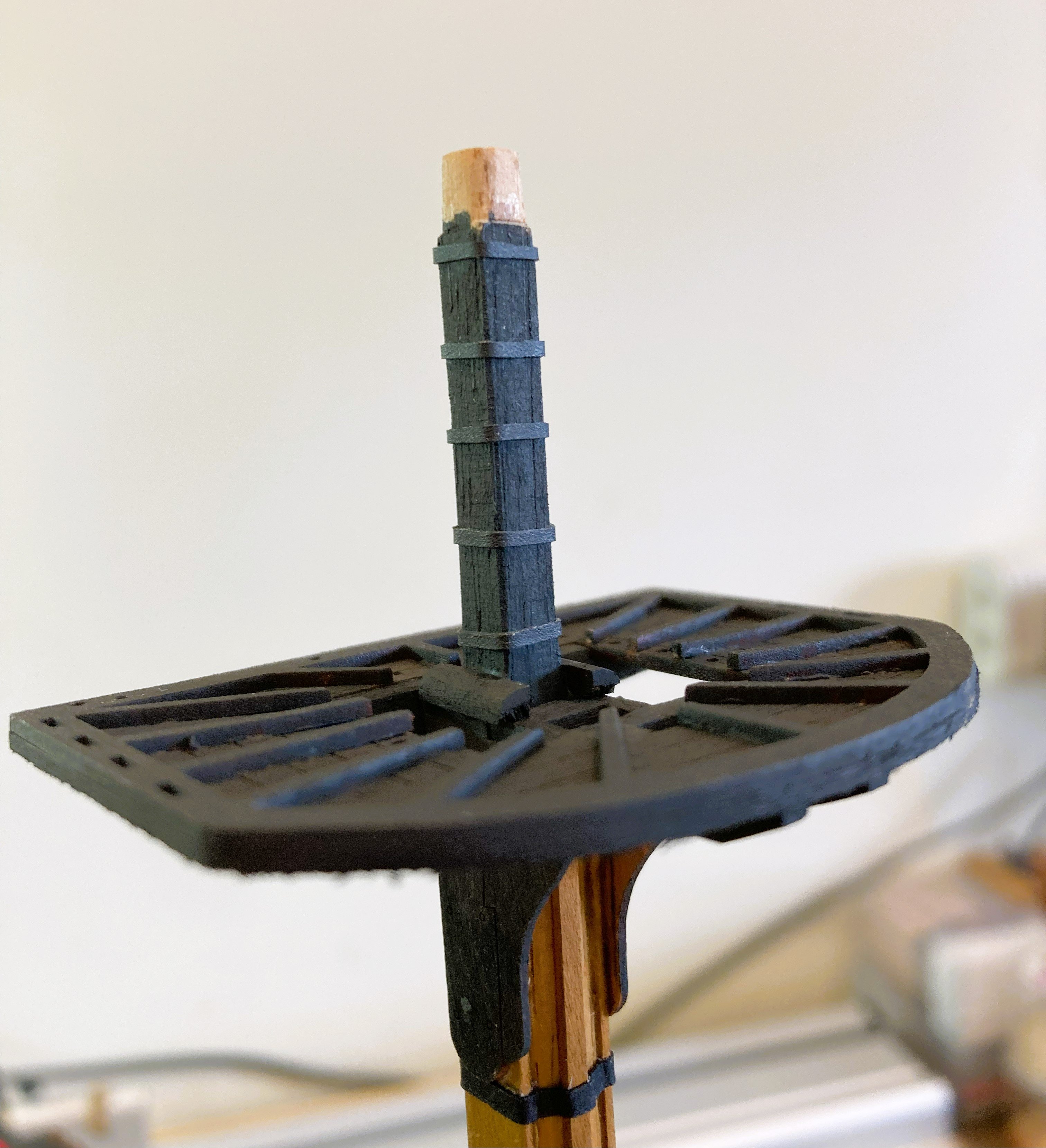
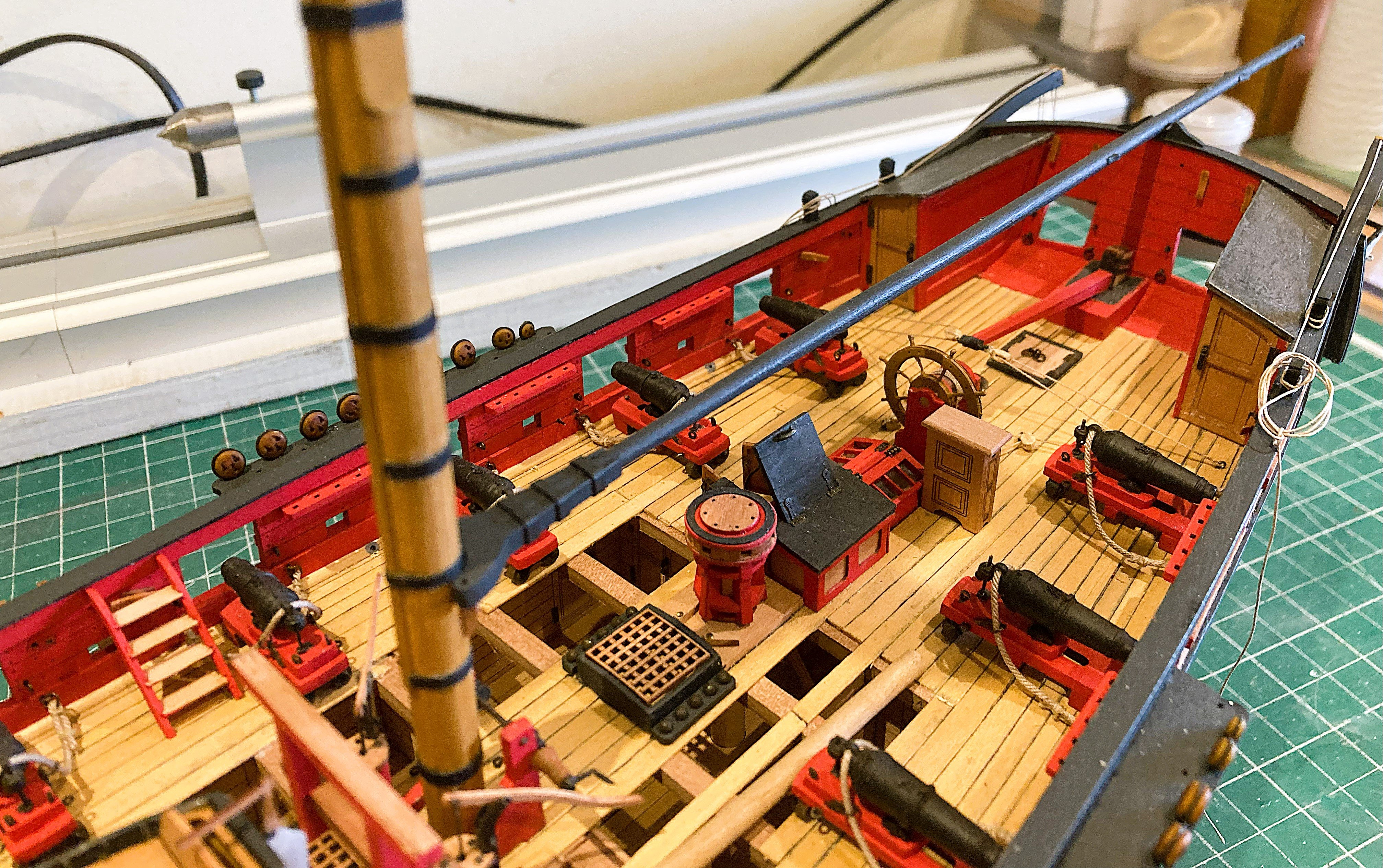
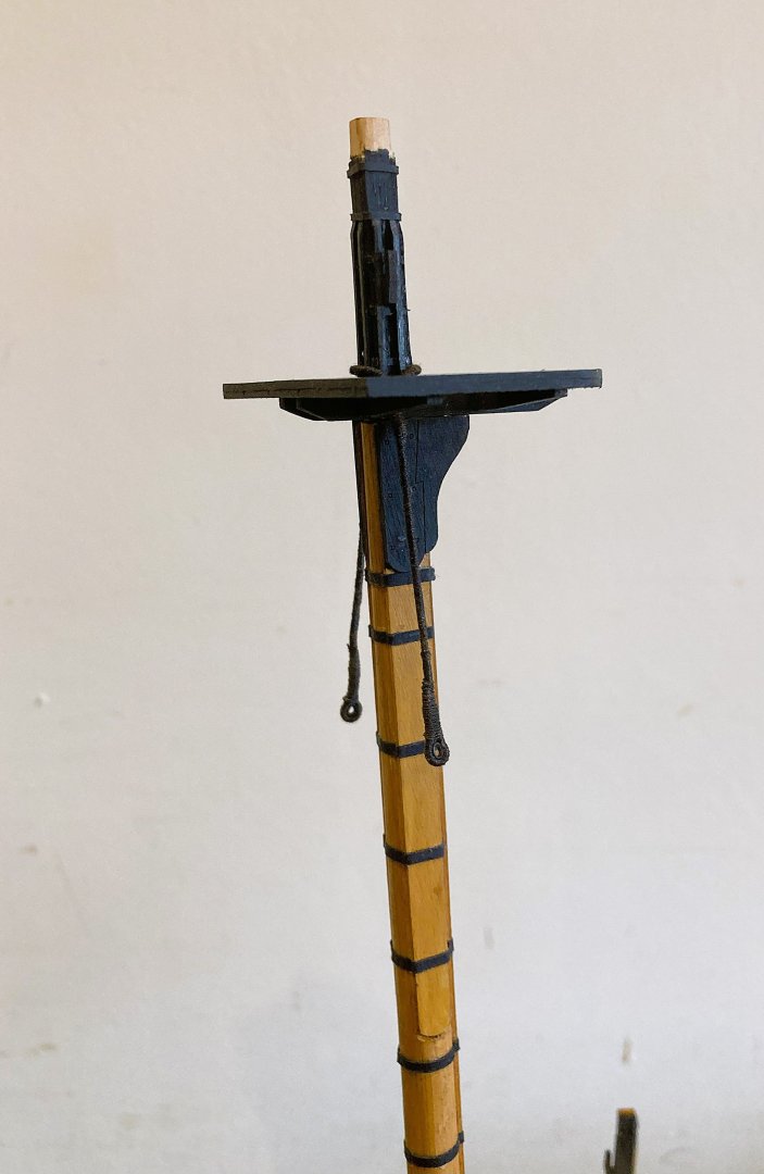
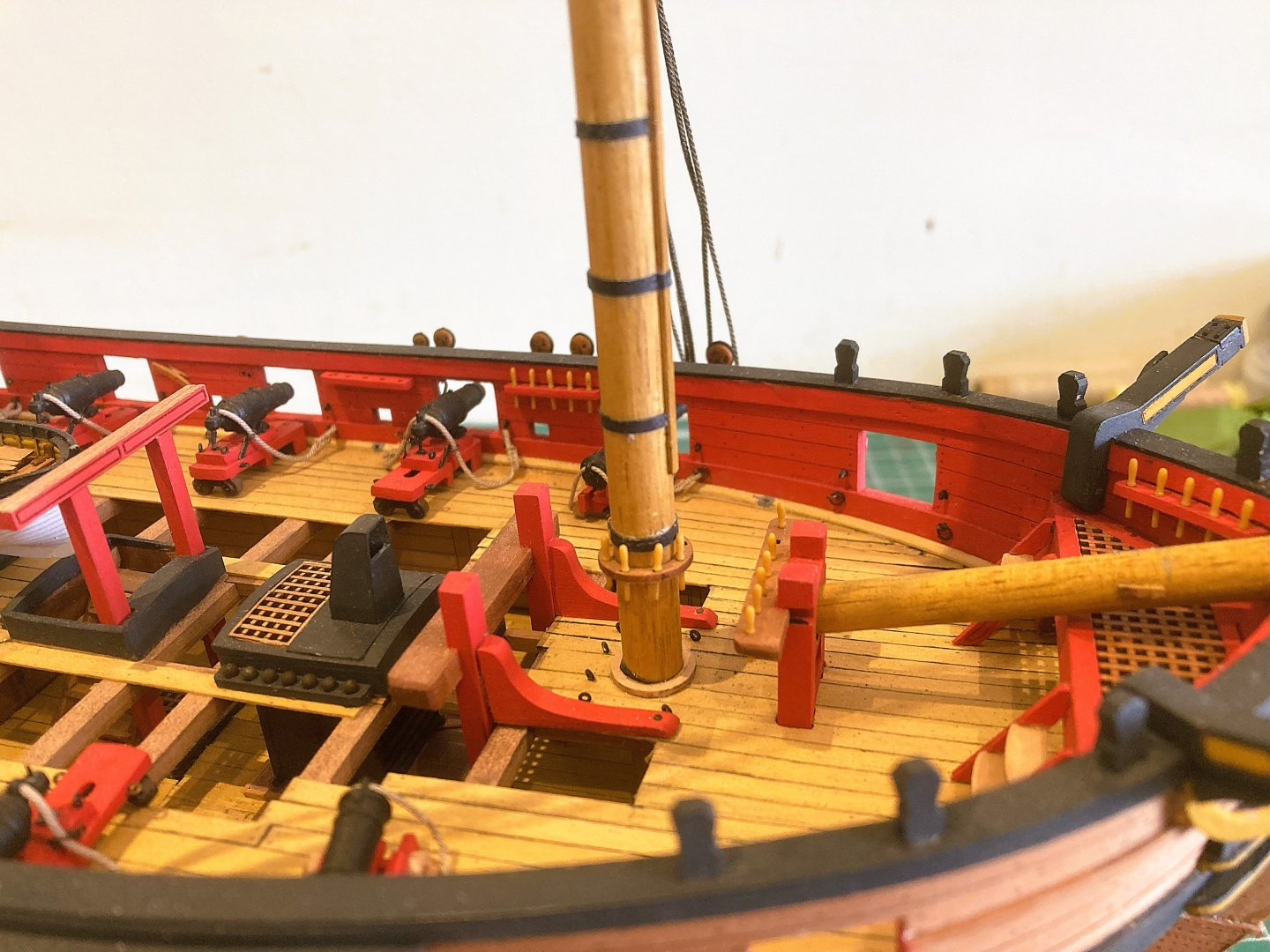
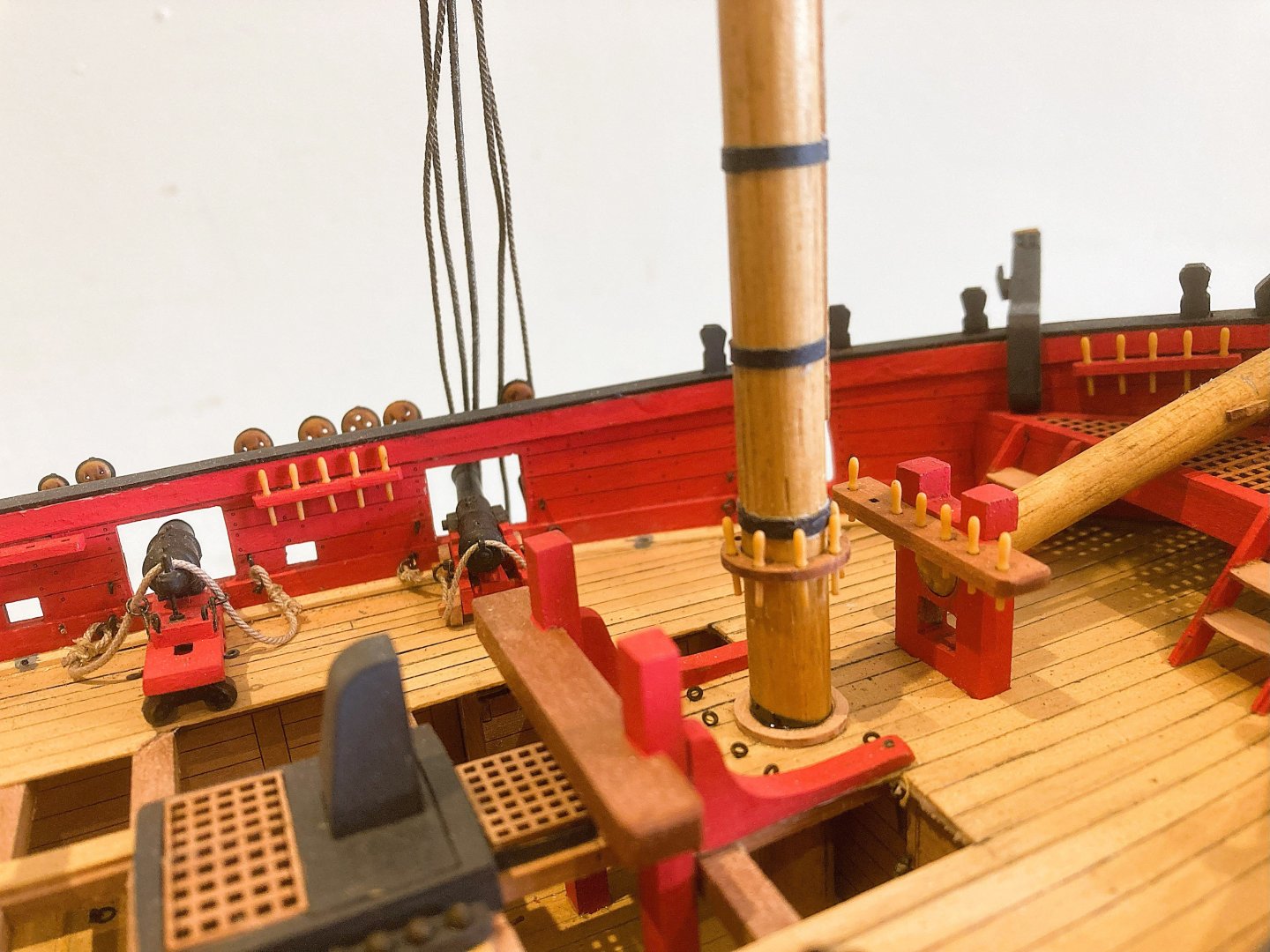
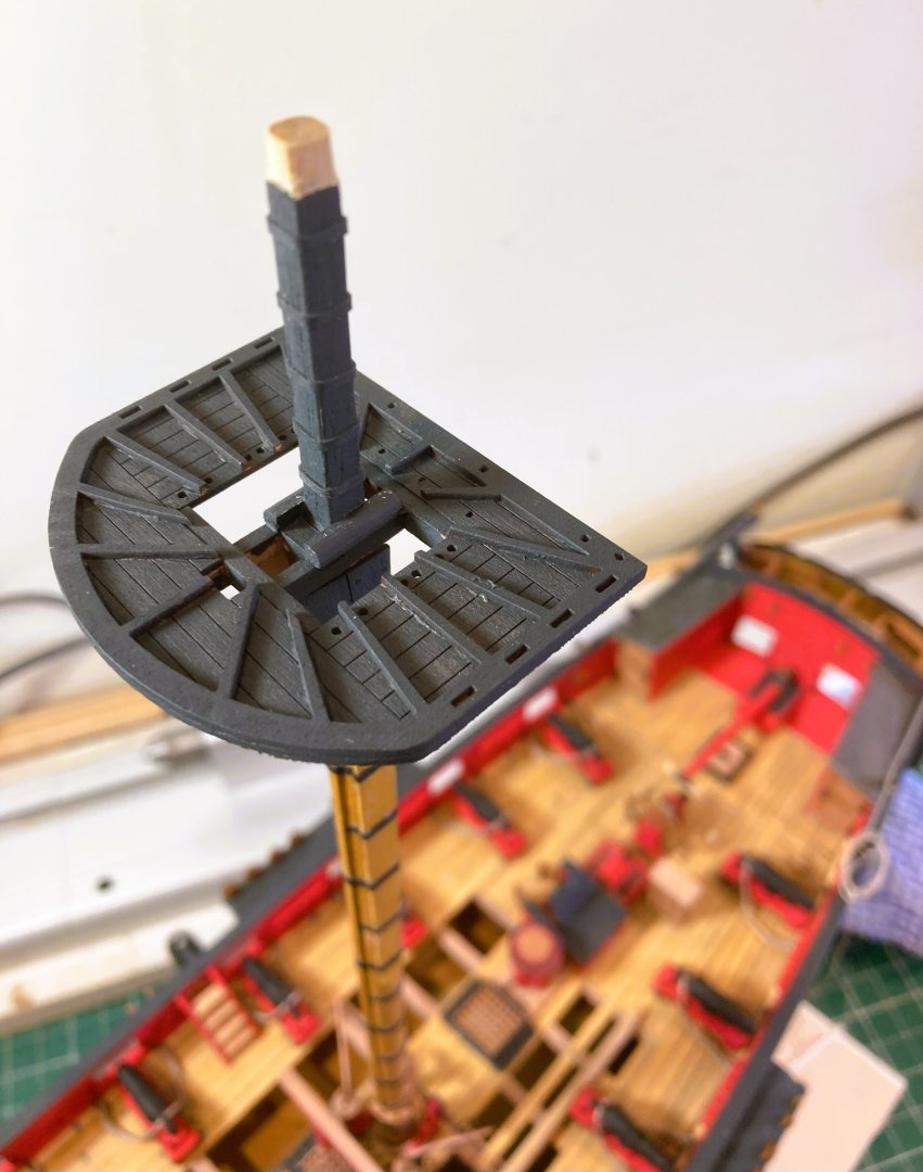
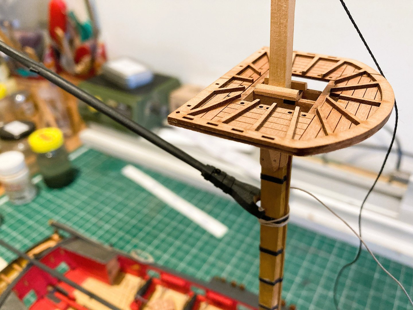
Post 84 Completing the masts. The Pin rails and a driver boom saddle are added to the lower mast sections. 4576a Fore mast Pin rail, beautifully cut slots for the pins. 4575a The Pin rail on the Mainmast really needs fitting before adding the lowest ‘iron’ mast band otherwise it won’t slide up to the correct position. The tops which are traditionally painted black down to the hounds, are now attended to. I used Vallejo Black/grey for the purpose. 4570a I love the planking detail Chris has engraved into the tops, I used a slightly thinner mix of paint in this area so as not to obscure the detail. 4579a There are five iron bands spaced equally along the Masthead. For these I used 1mm slices from heat shrink tubing. This gives a subtle shade difference to the painted head. Atop the iron bands are a series of battens designed to protect the rigging from wear. 4581a Kit provided pieces are of 0.6mm strips which I found a little thin to notch over the bands. I replaced these with some slightly thicker strip which allowed a shallow notch to be cut. There are eight of these on each masthead; a small detail the top ends should be sniped to follow practice. Steel also notes that; battens should have rounded edges for the rigging to slide down easily. 4603a Steel also notes that; The afterside of Mizen masts in ships, and mainmasts in brigs, to be coppered in the wear of the gaff and boom. An easy addition using copper tape if so motivated. 4604a 4606a 4607a I now have the overall size of my model version which will require a cover of 30”L x 9” W x 16” H. I can get this organised while I continue with the build. B.E. 04/06/2025


- 332 replies
-
- 20
-
-
- Harpy
- Vanguard Models
- (and 1 more)
-
Wonderful stuff you are now producing Chuck, and I think us modellers appreciate the extra mile you go. It has been a great experience using your resin blocks and deadeyes, and the other little detailed fittings. Did you decide whether to produce the Belay pins at 1:64 scale? Regards, B.E.
-
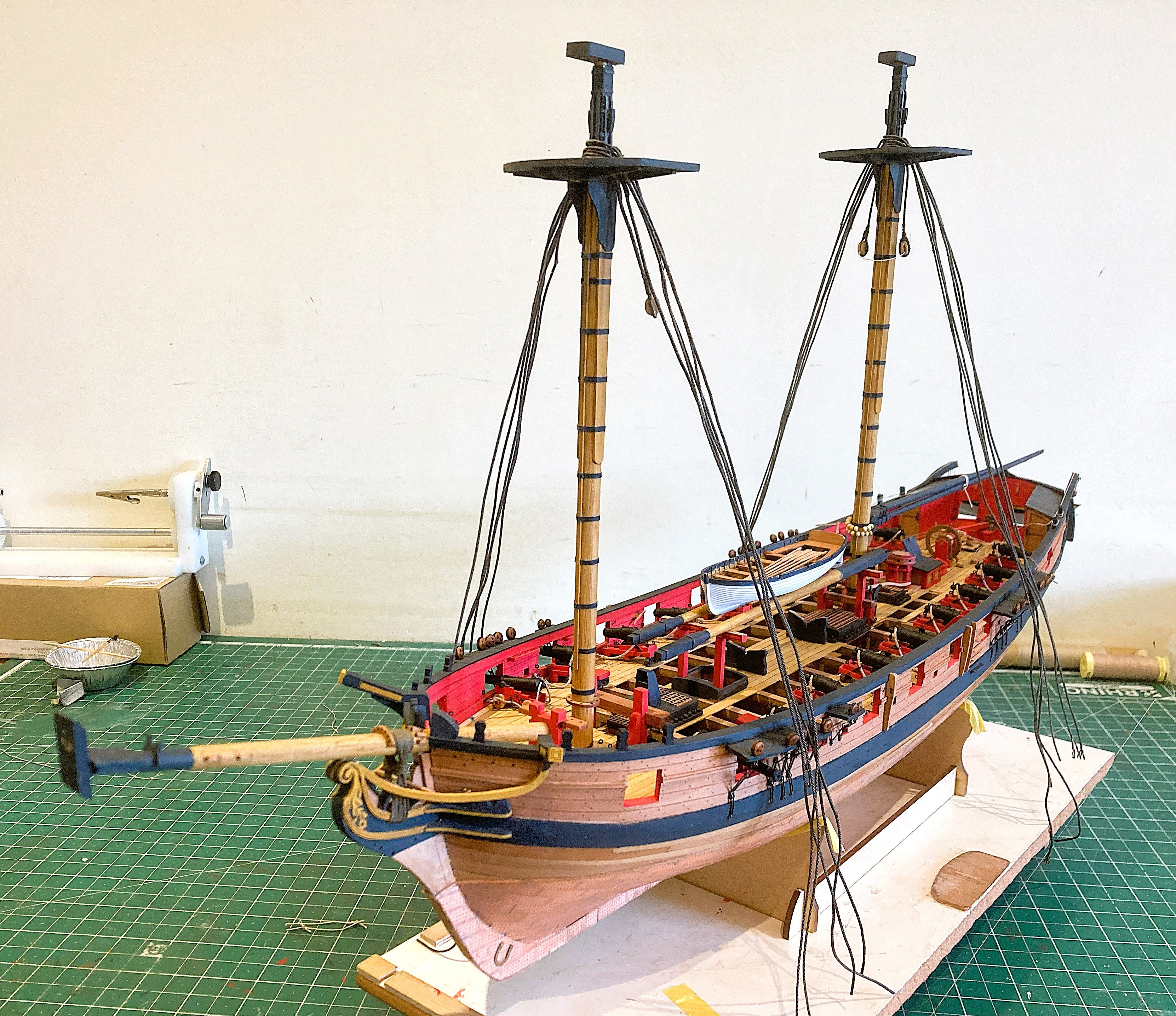
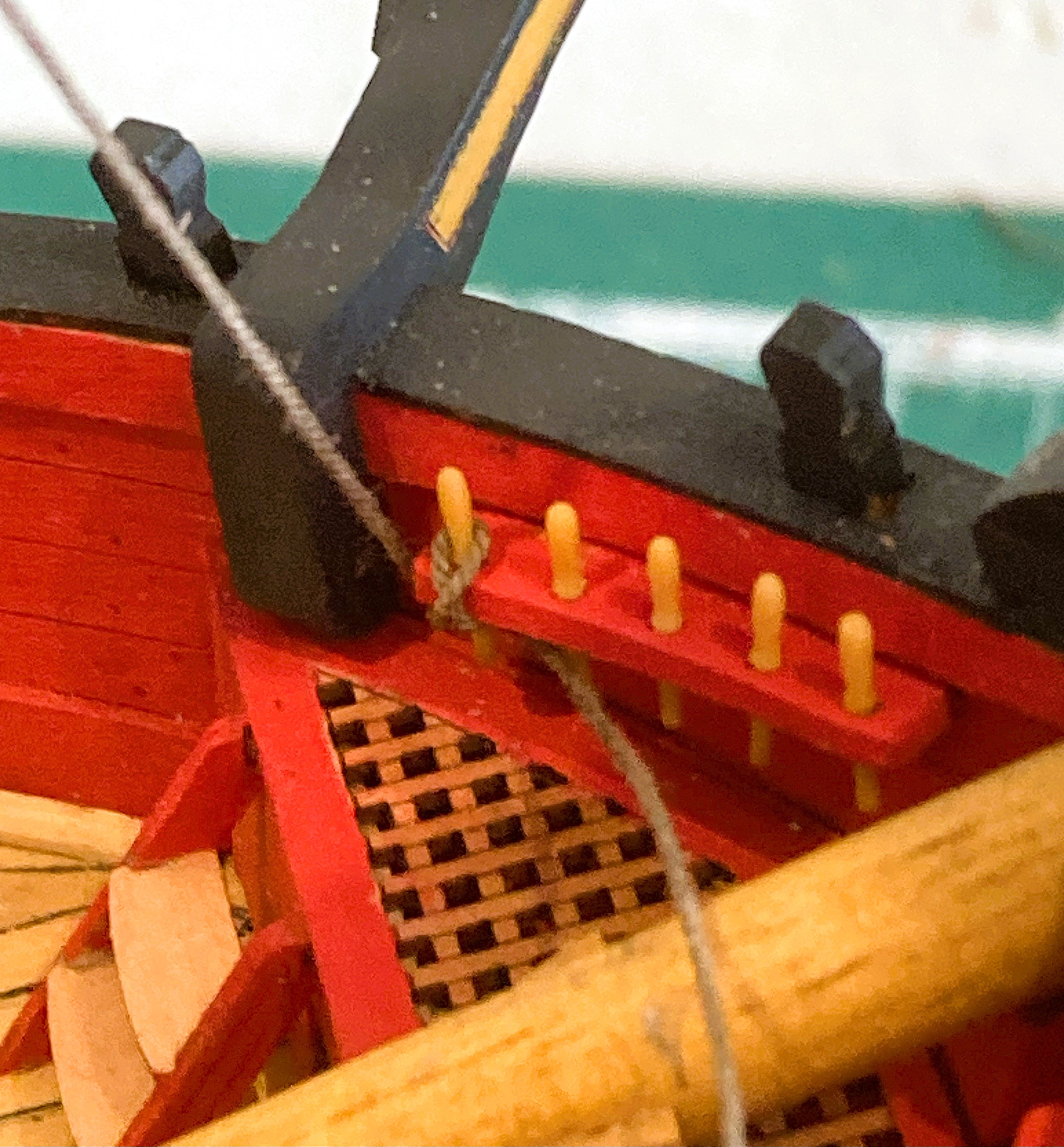
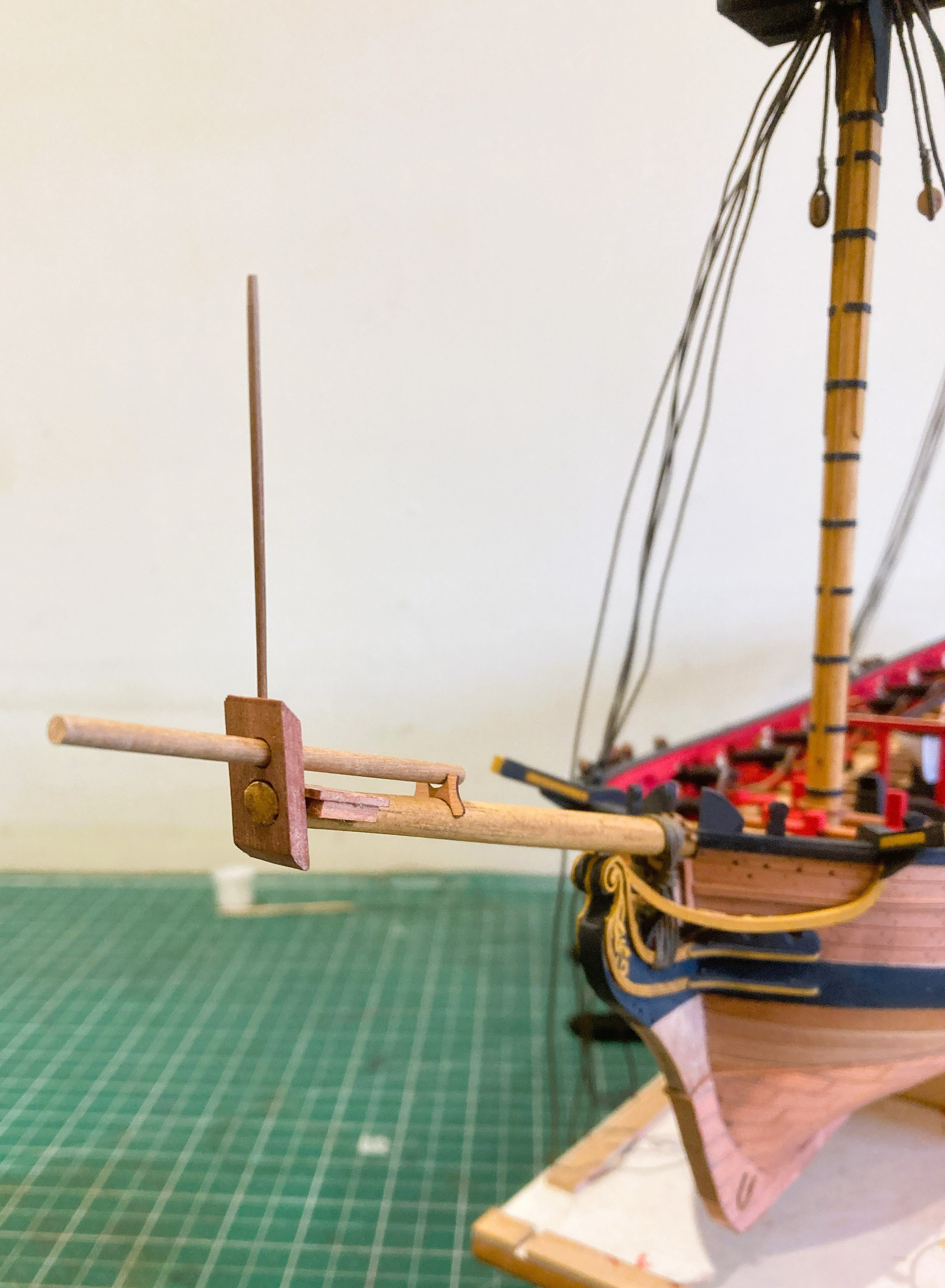
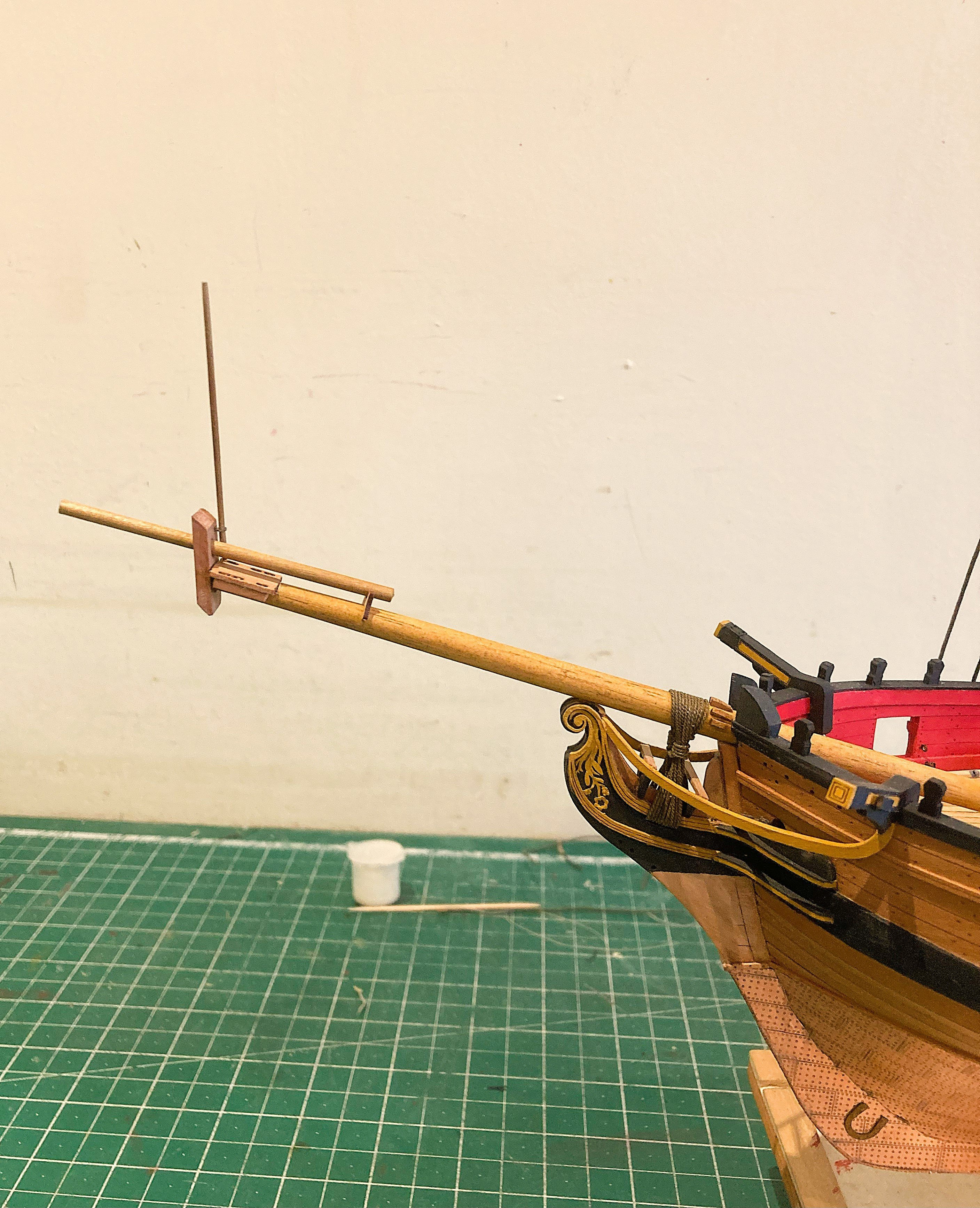
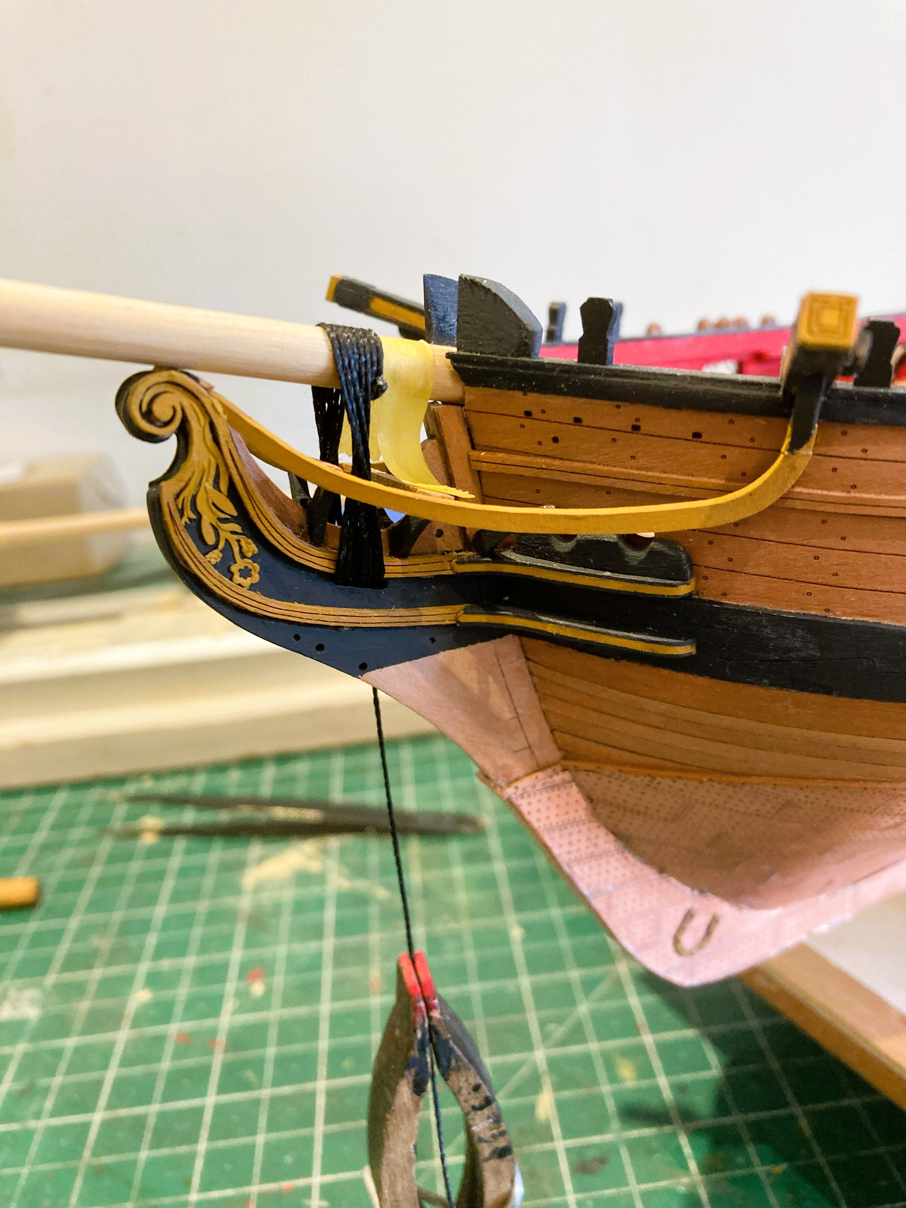
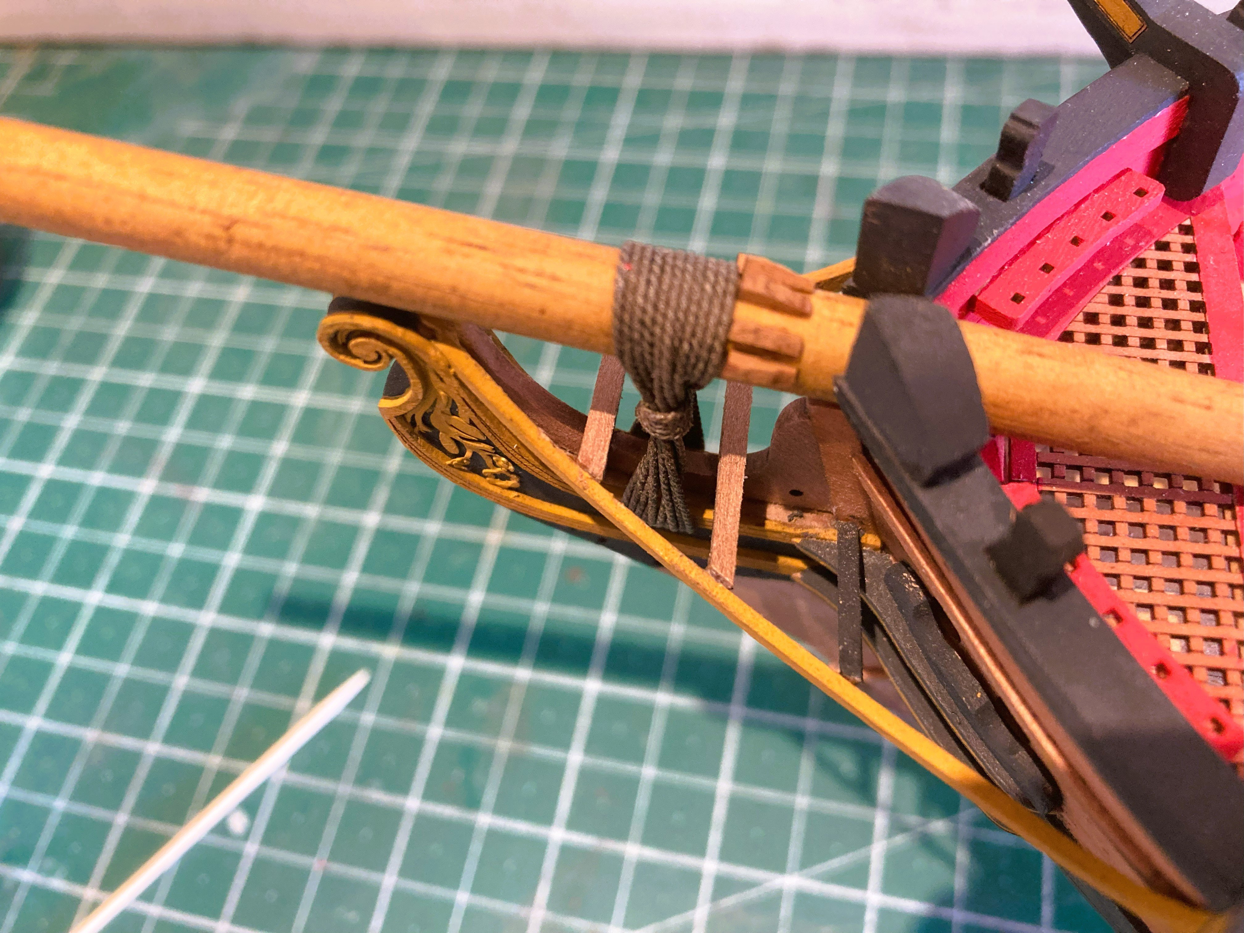
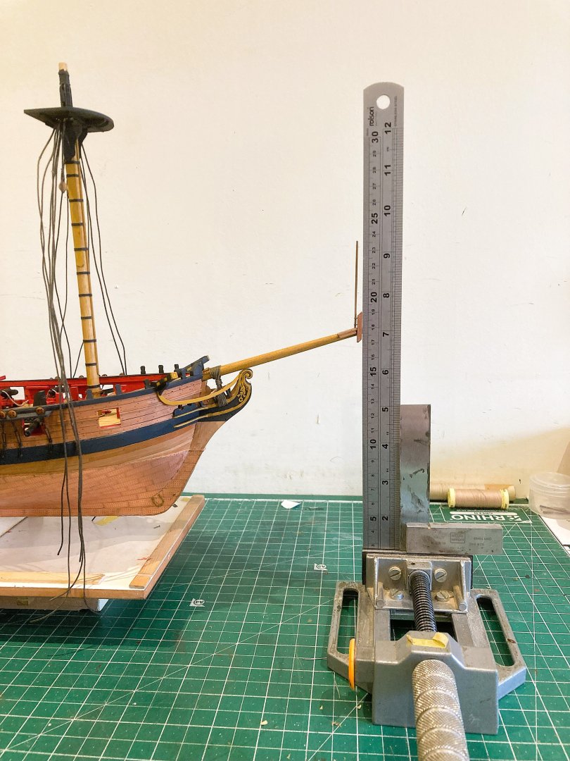
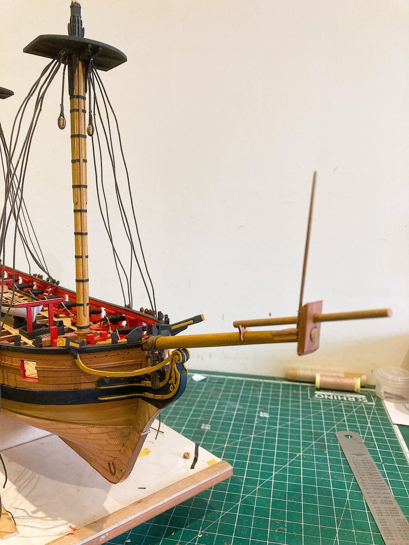
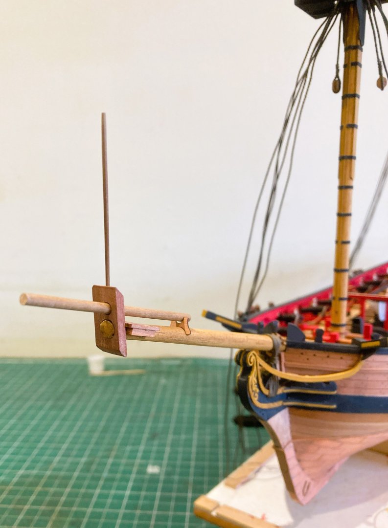
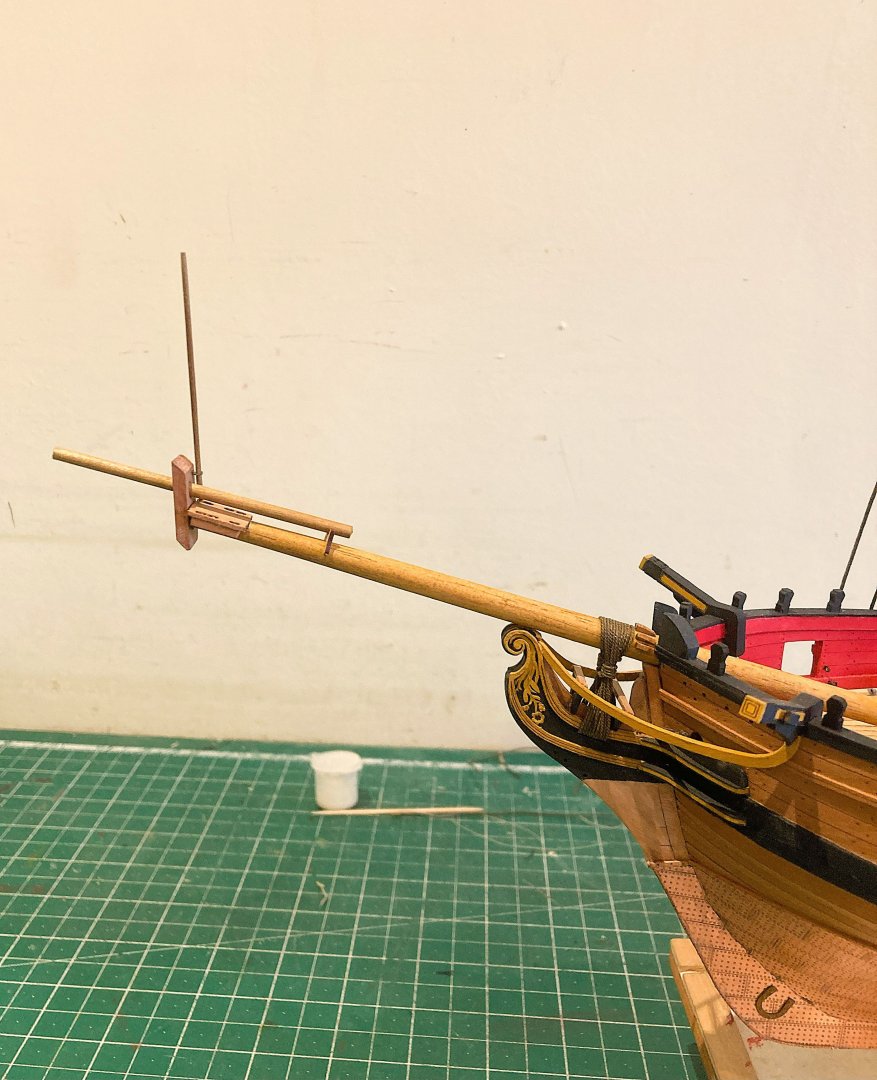
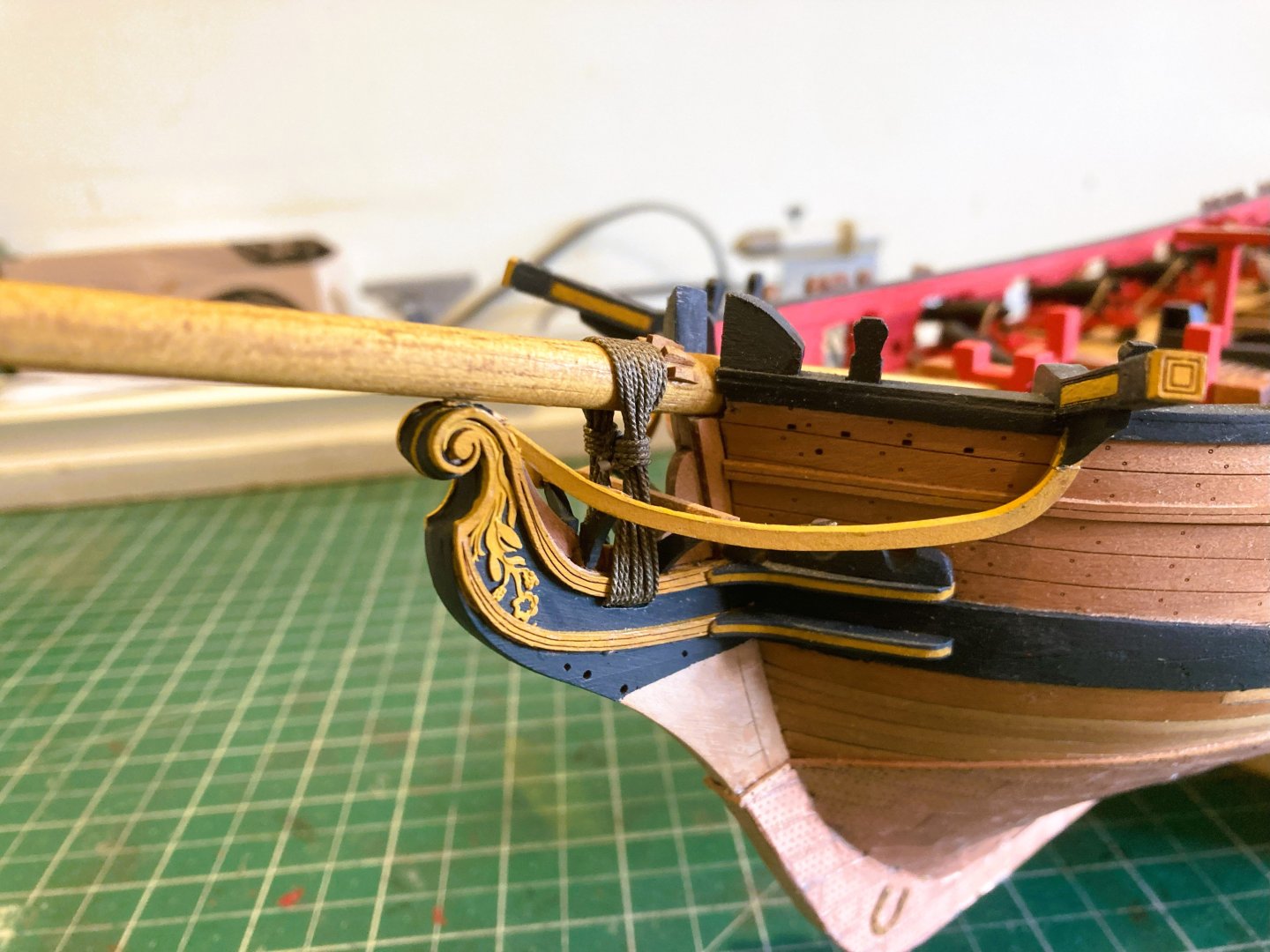
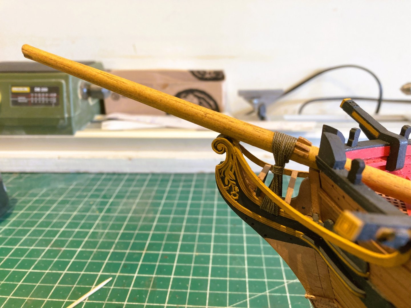
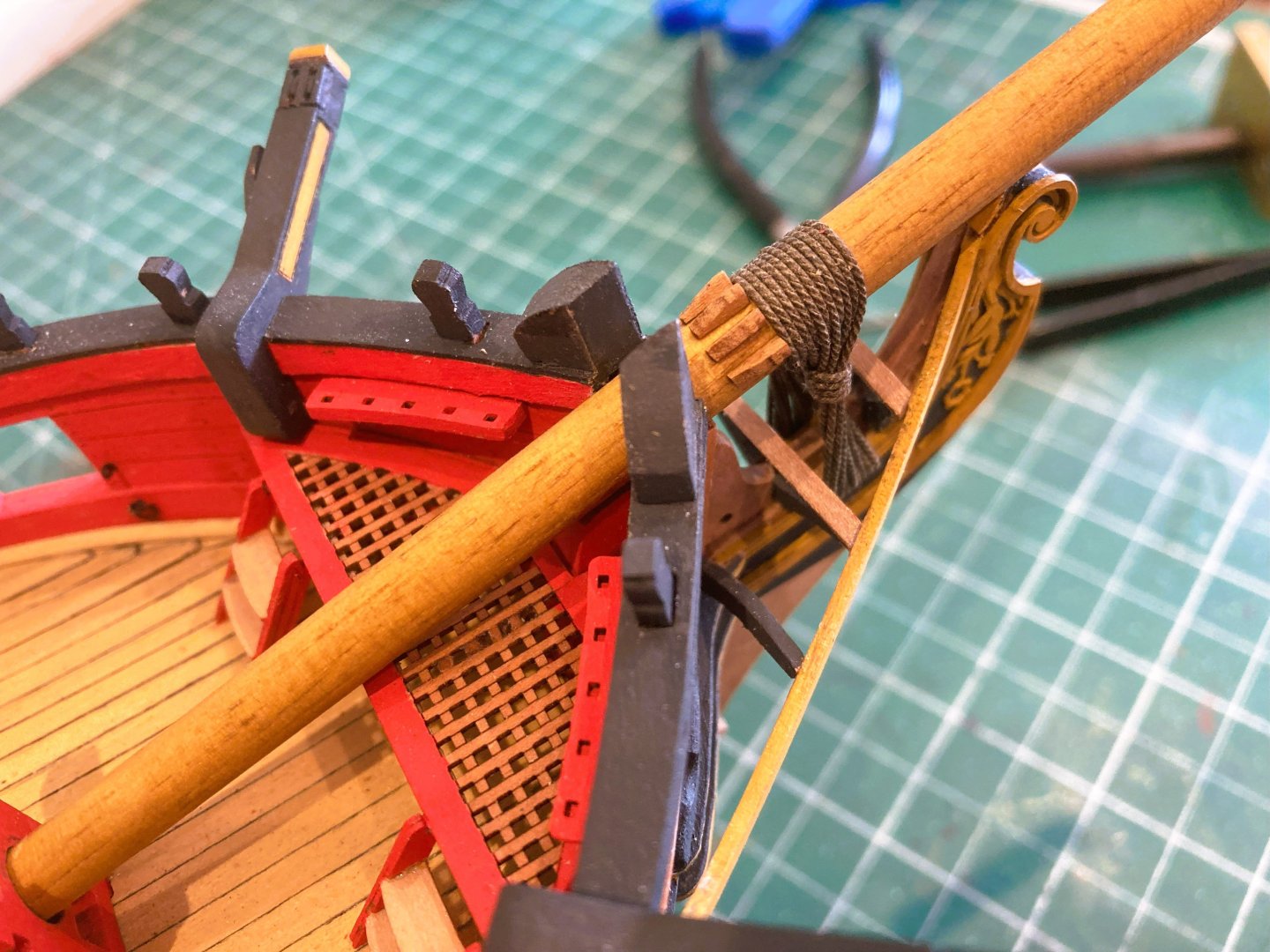
Post 83 Bowsprit My eye had been drawn to the Bowsprit as looking a little underweight compared to the Mainmast. My understanding is that Bowsprits are generally the same diameter as the Mainmast (at the Partners). The Adm plan does seem to show the Bowsprit diameter as being comparable to the Mainmast. As you may expect there are rules, and for Bowsprits of a given gross diameter a proportional taper is applied at each quarter along the length to the outer end, and inboard to the heel. Heel 1stQ 2ndQ 3RDQ Outer end. 6/7 60/61 11/12 4/5 5/9 Long story short, having compared information from Steel I decided to use a 8mm dowel reduced to 7mm+ on the lathe, before the proportions were applied. Between the Head Timbers (Knightheads) I had to accept a degree of compromise, settling for a diameter of 6.6mm. This also involved a little sanding of the Head timbers to allow passage. The Bowsprit was tapered to 5.8mm at the step, and 4.7mm at the outer end. I had initially used a 6mm dowel to check the position of the gammoning cleats. 4503a A Gammoning test line was applied to mark the position. 4556a I used Syren 0.63mm ø line for the Gammoning which I dyed using Dark Jacobean wood dye. This is something I do for all standing rigging as I prefer the look to kit supplied black line. Note: The Gammoning line has twist in it; Starting on the port side each successive turn goes over the Bowsprit forward, and crosses the previous line aft as it runs thro’ the gammoning slot. The line is completed with frapping turns around the centre and seized off. 4565a Gammoning completed on the replacement Bowsprit. The Gammoning cleats are very small; I found that attaching them to double sided tape was sufficient to hold them for a light cleaning up. 4564a Ramin dowel was used to make the Bowsprit I used w-o-p on the Bowsprit followed by a light oak dye concoction to match the masts. 4558a I am not quite decided how much more detailing of the Bowsprit I will do, it is there primarily for the attachment of the Fore Stay. The next stage is completing the mast detail and onto the shroud rigging. B.E. 02/06/2025


b.jpg.19971d5f0f61d53844c59427e68d6b1b.jpg)
- 332 replies
-
- 13
-
-
- Harpy
- Vanguard Models
- (and 1 more)
-
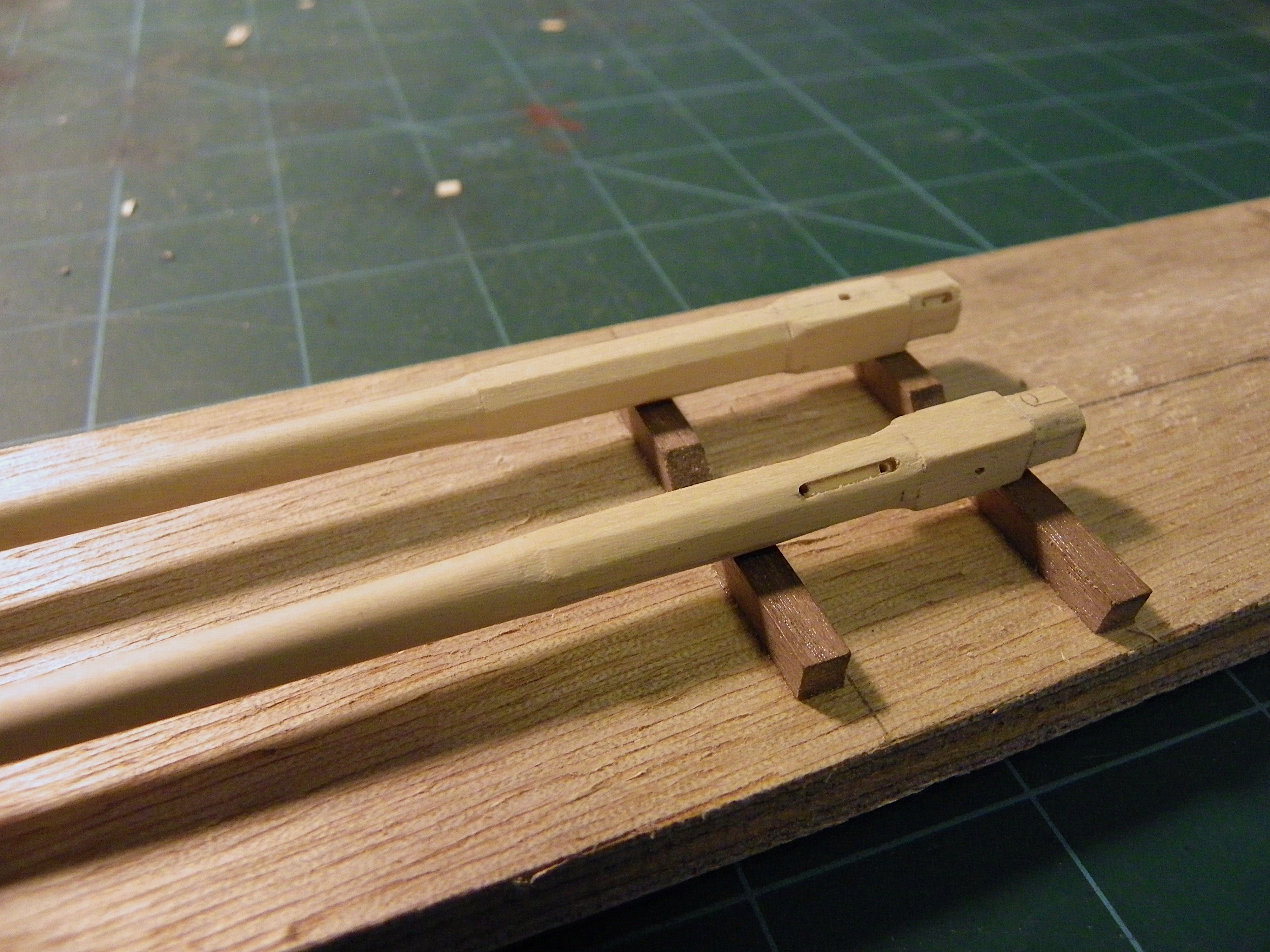
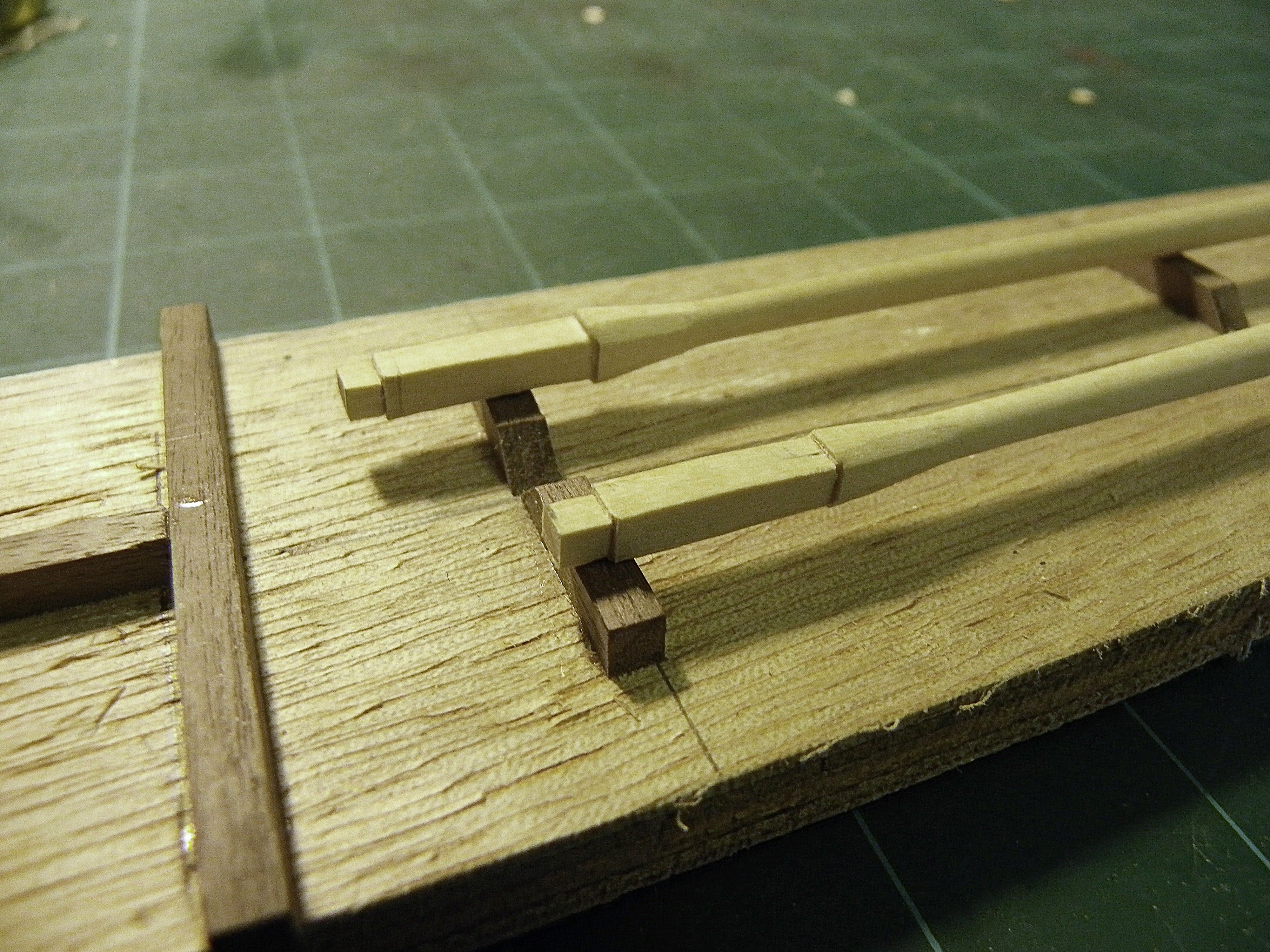
Cheers Guys for your comments and 'likes' much appreciated.👍 Post 82 Boom and Gaff I have spent a couple of days looking at the two booms I will include with my model. An interesting use of terminology here. What we may generically know as Driver Booms are referred to by Steel as Main Booms in relation to cutters and Sloops. Again, there are defined proportions relating to Driver/Main Booms. The Steel tables indicate subtle differences in the taper arrangements between Driver booms and Main Booms, mainly in relation to the position of the widest diameter, but the differences at 1:64 scale are minimal. Driver Booms – largest diameter – mid point along the boom Main Booms - largest diameter - Position of the sheet – just inside the Tafferal. The sizes of booms is confusing, it must be tricky to decide what to apply to the Harpy Kit. Unfortunately Steel doesn’t have tables relative to Brig Sloops. The kit Main Boom seems to be based on a 200 ton Brig with a Boom diameter of 10½” – 4mm at scale. Harpy is a 316 ton vessel, yet a Sloop of 300 tons has a Boom diameter of only 7⅜”- 3mm at scale. There are also defined proportions set out in Steel for Gaffs Length of Gaffs 5/8 of respective booms, diameter of Gaffs -same as booms. The kit seems to follow these proportions. 4529a Both booms were shaped on the lathe using sanding papers. 4540a 4542a I note that the boom jaws lack iron bands which were common for these items. I used heat shrink tubing for the purpose, but black card would suffice. The Gaff On my build I found the jaws a tad too small to fit around the mast in the raised position even tho’ the overall mast dimension including the cheeks is the correct diameter. 4554a Here I have thinned down the jaws as much as I dare but the fit is not ideal. 4549a 4550a 4551a Fortunately, on my build the Gaff will be in the lowered postion where the fit is fine. Had I been rigging the Gaff in the raised position I would have to re-do the Gaff for a better fit, probably by splitting the jaws and re-attaching with a slightly less tapered boom at the inboard end. B.E 01/06/2025


- 332 replies
-
- 19
-
-
- Harpy
- Vanguard Models
- (and 1 more)
-
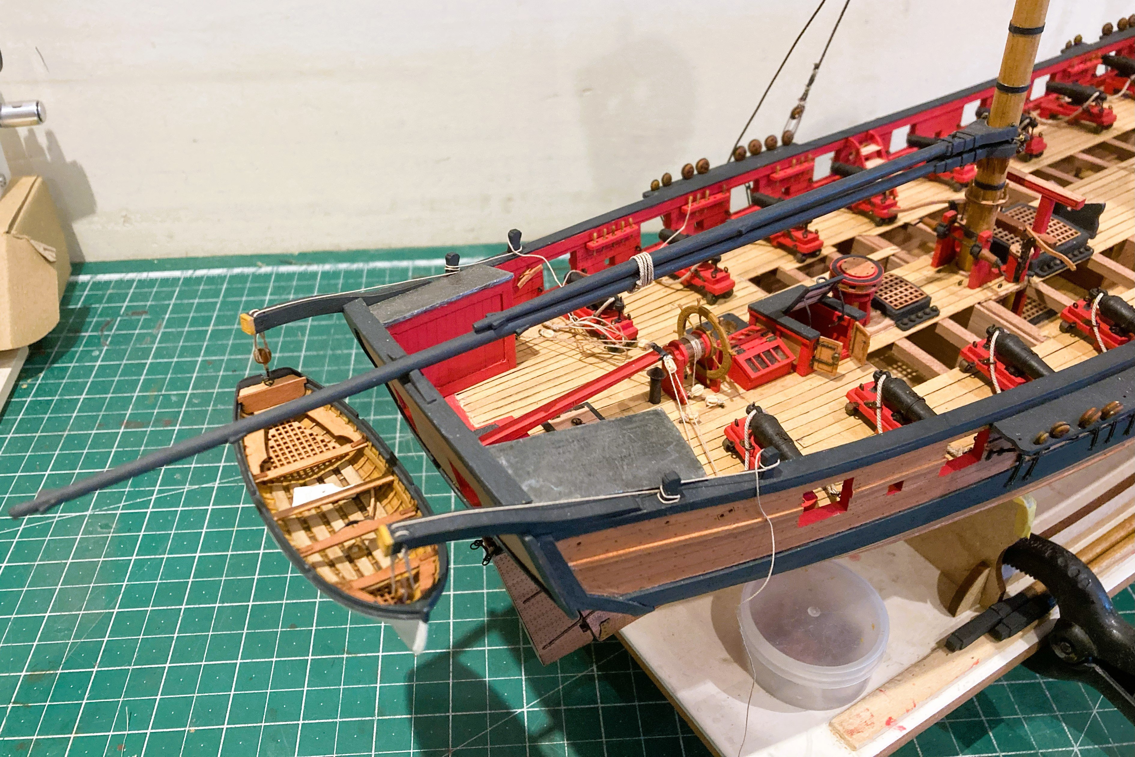
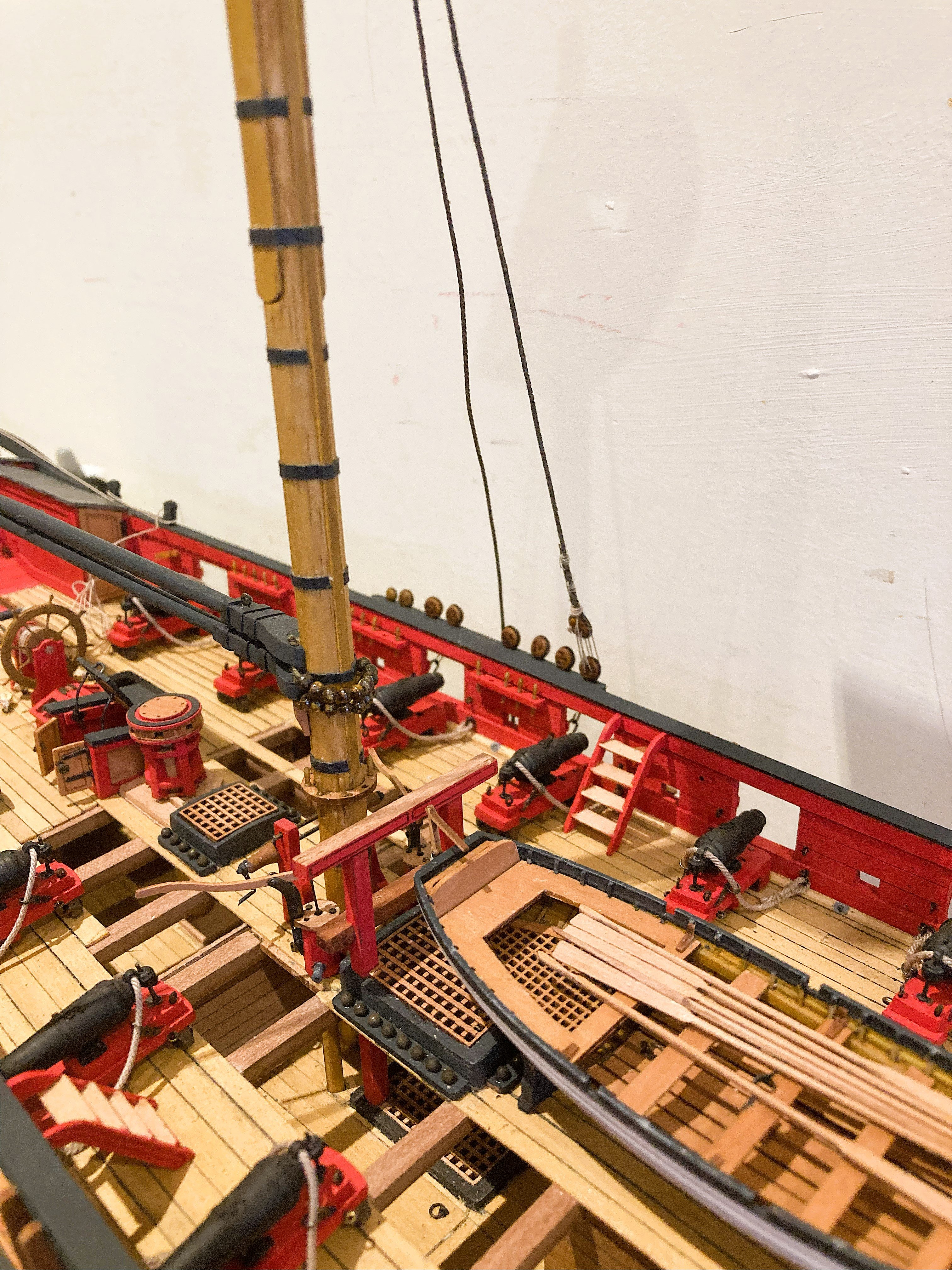
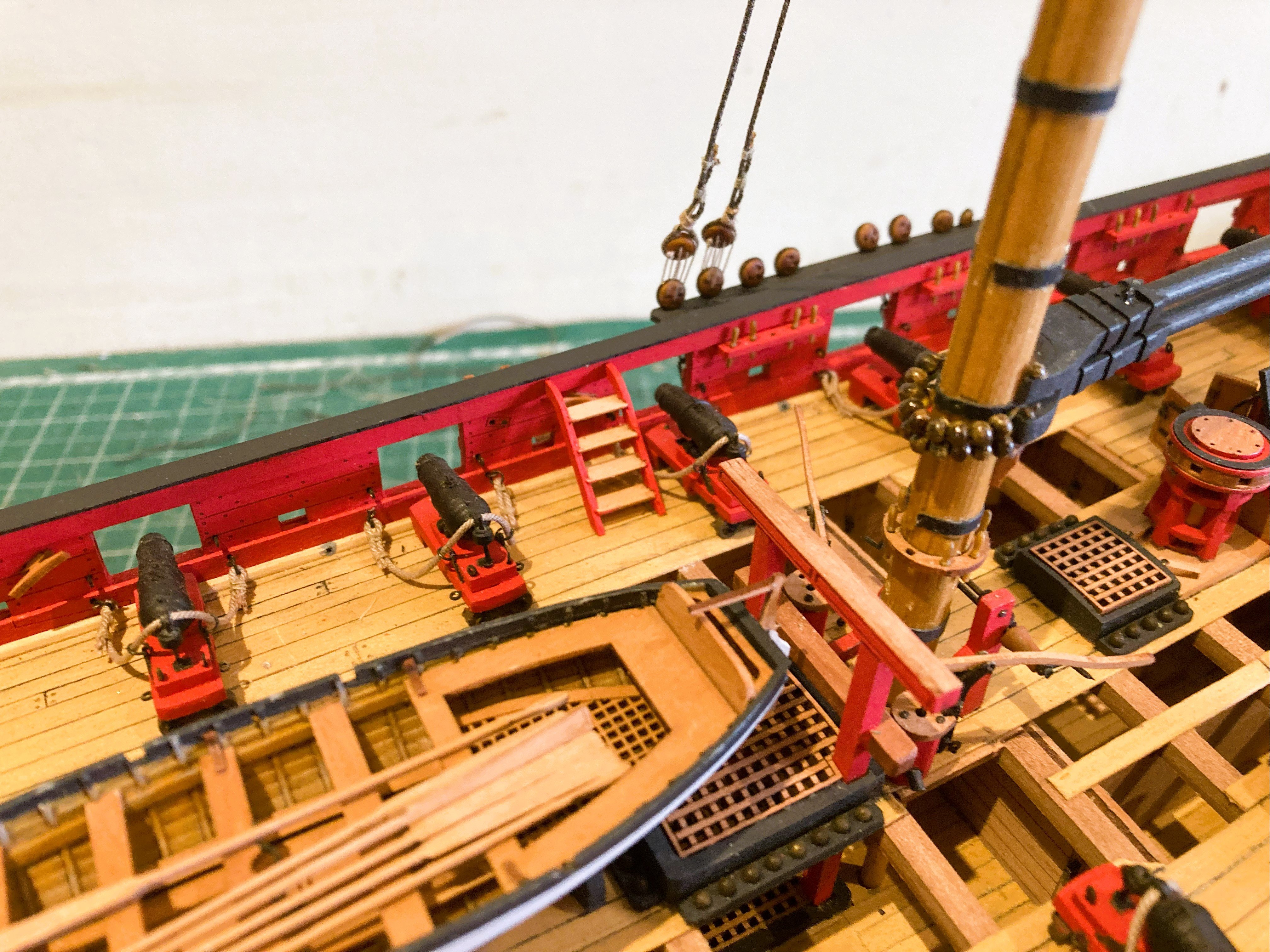
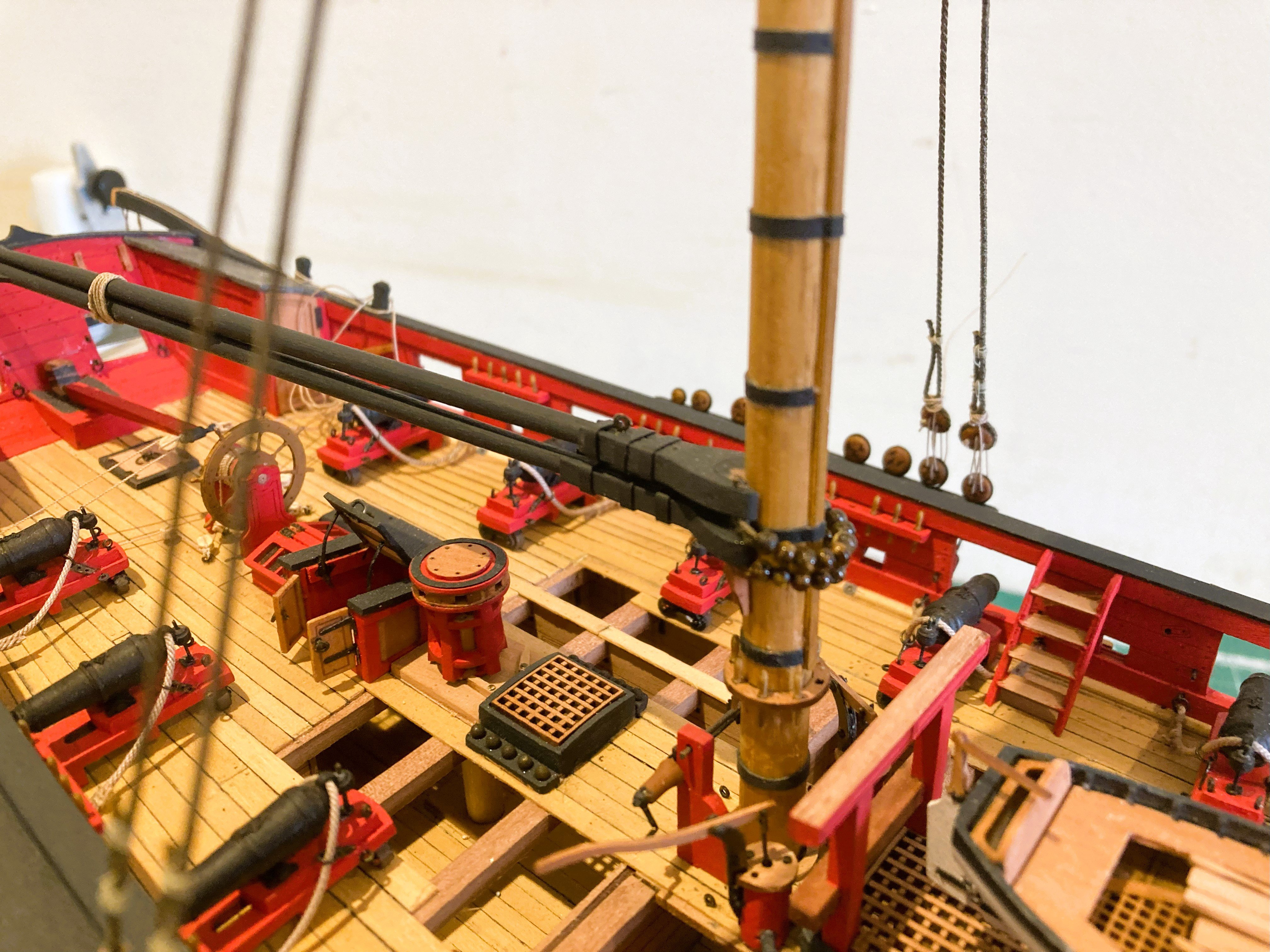
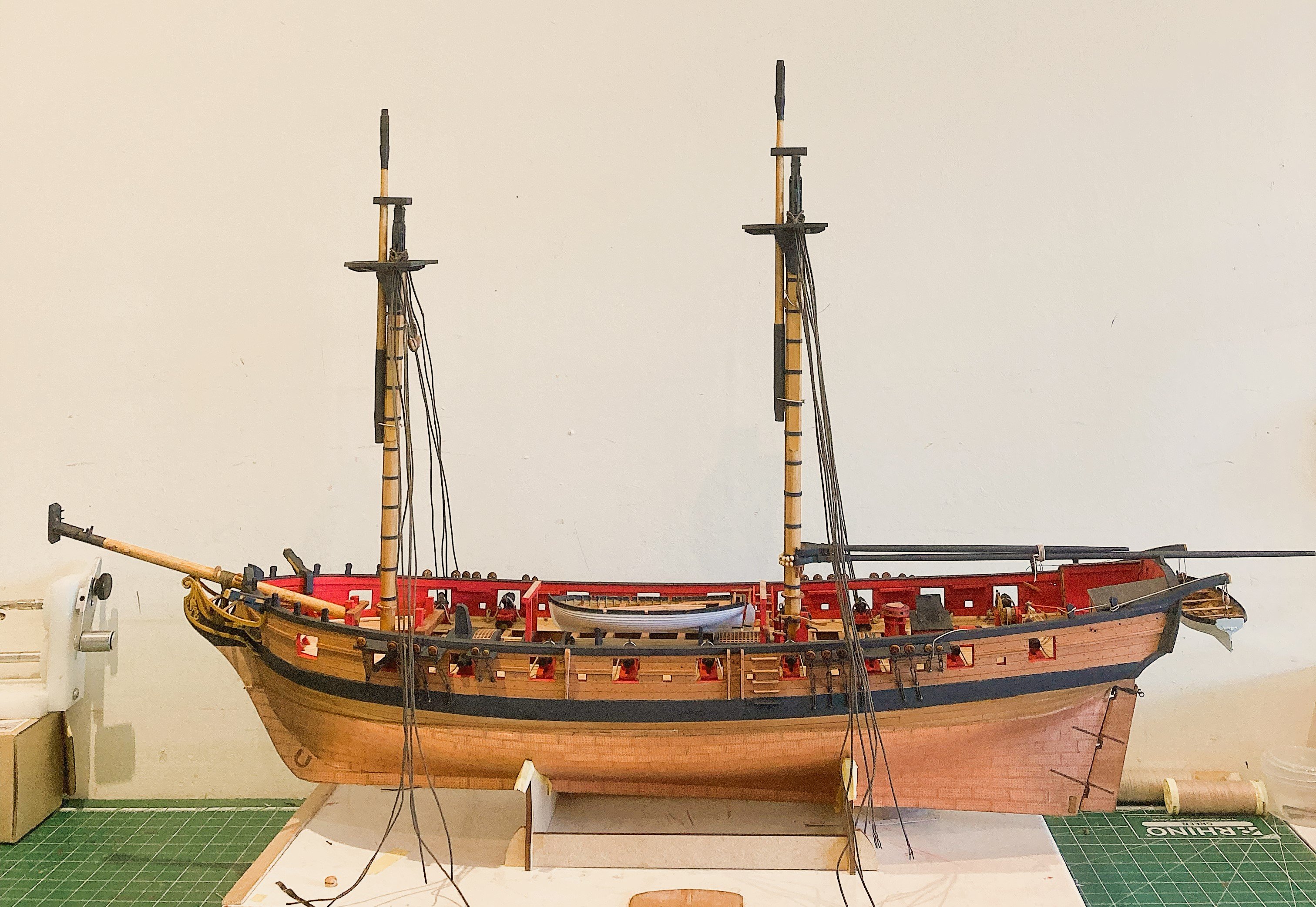
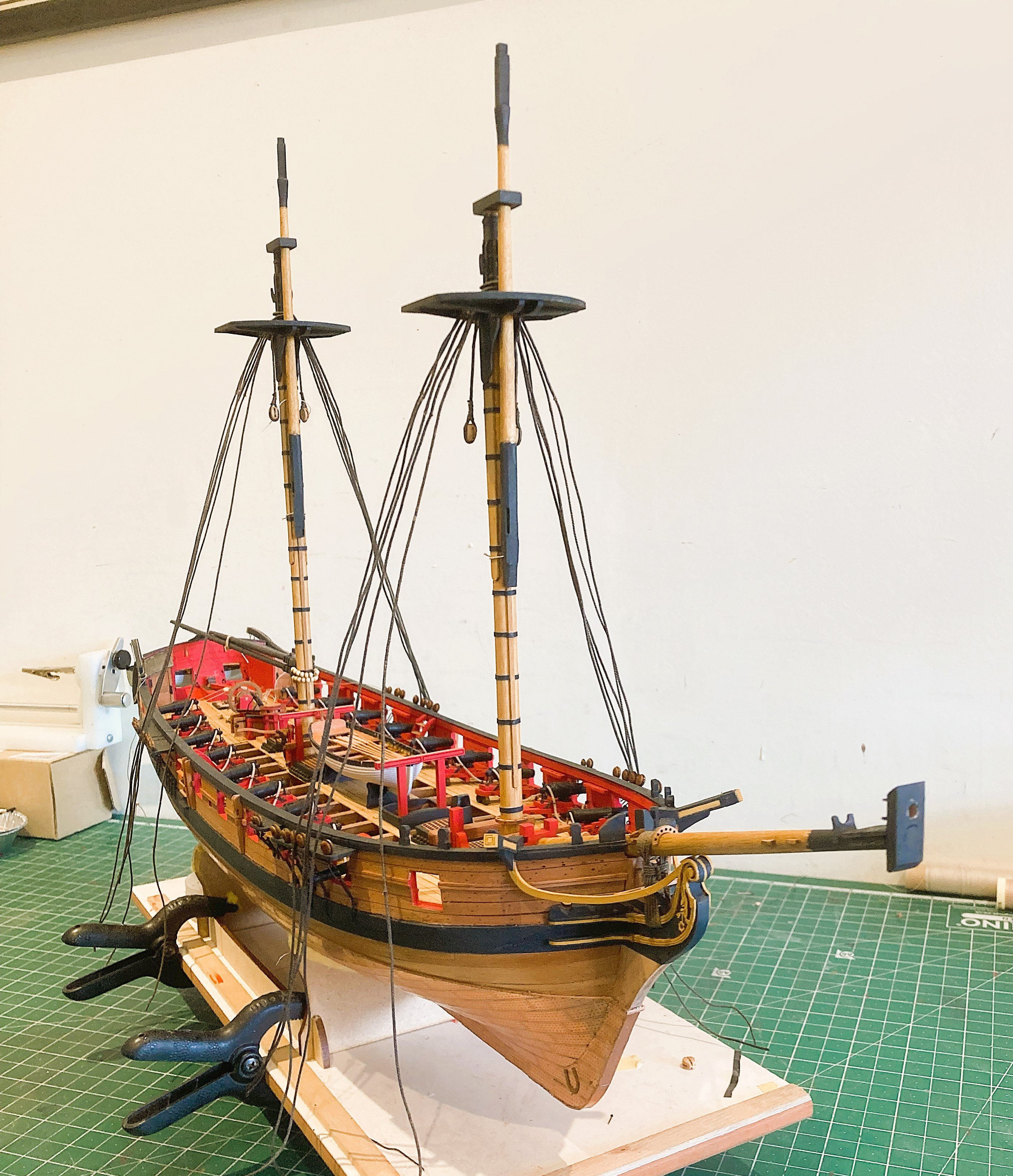
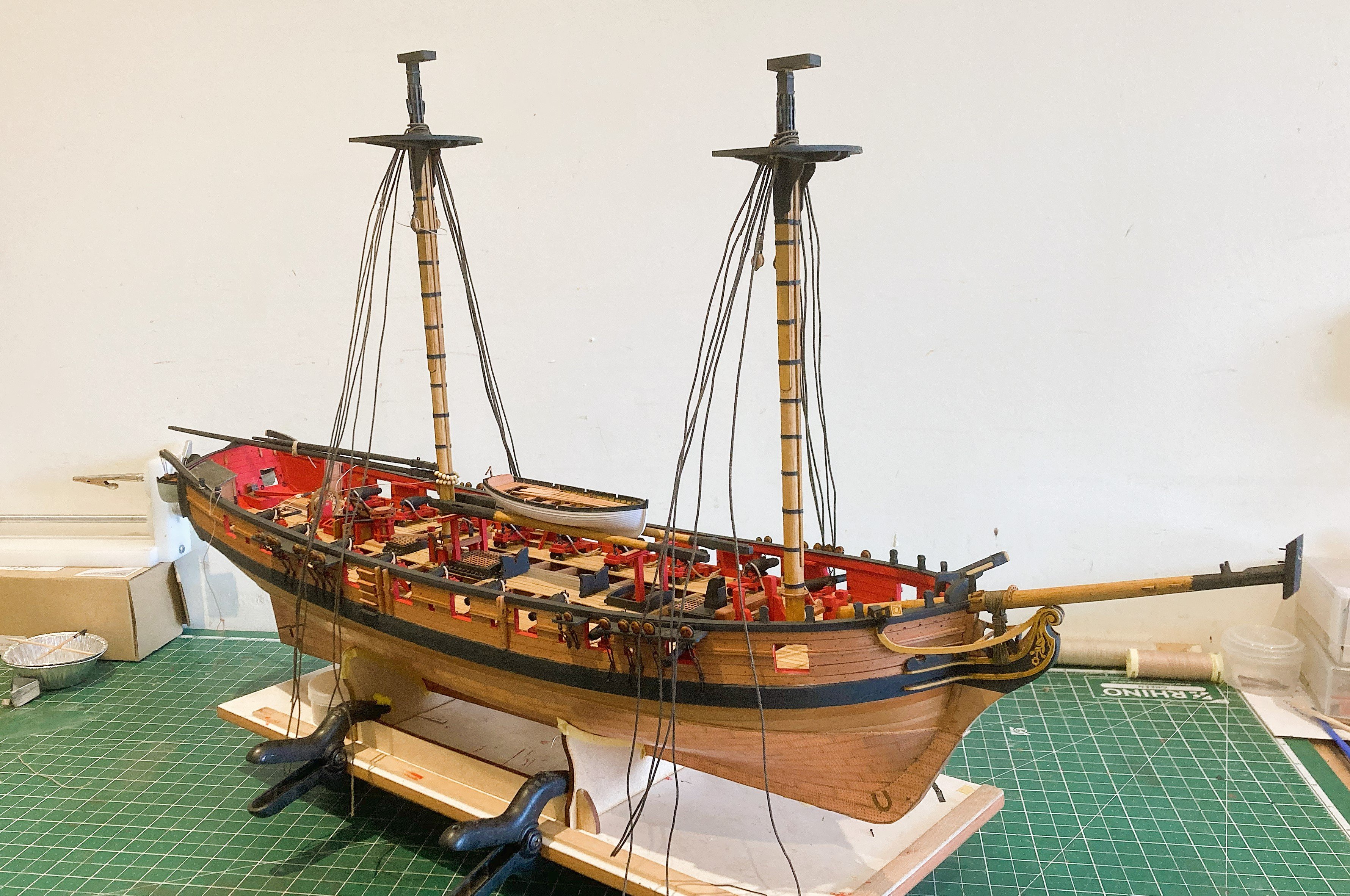
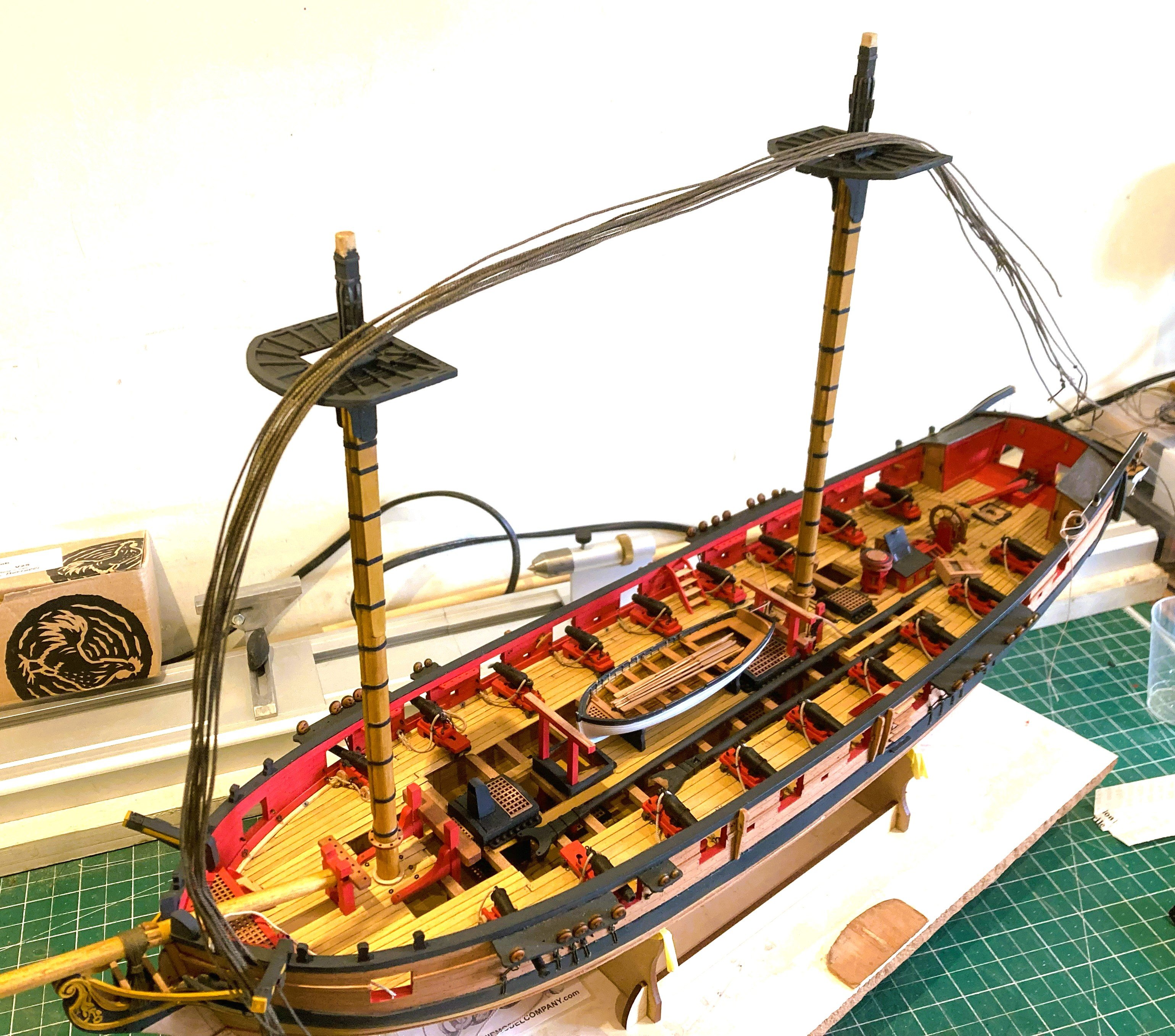
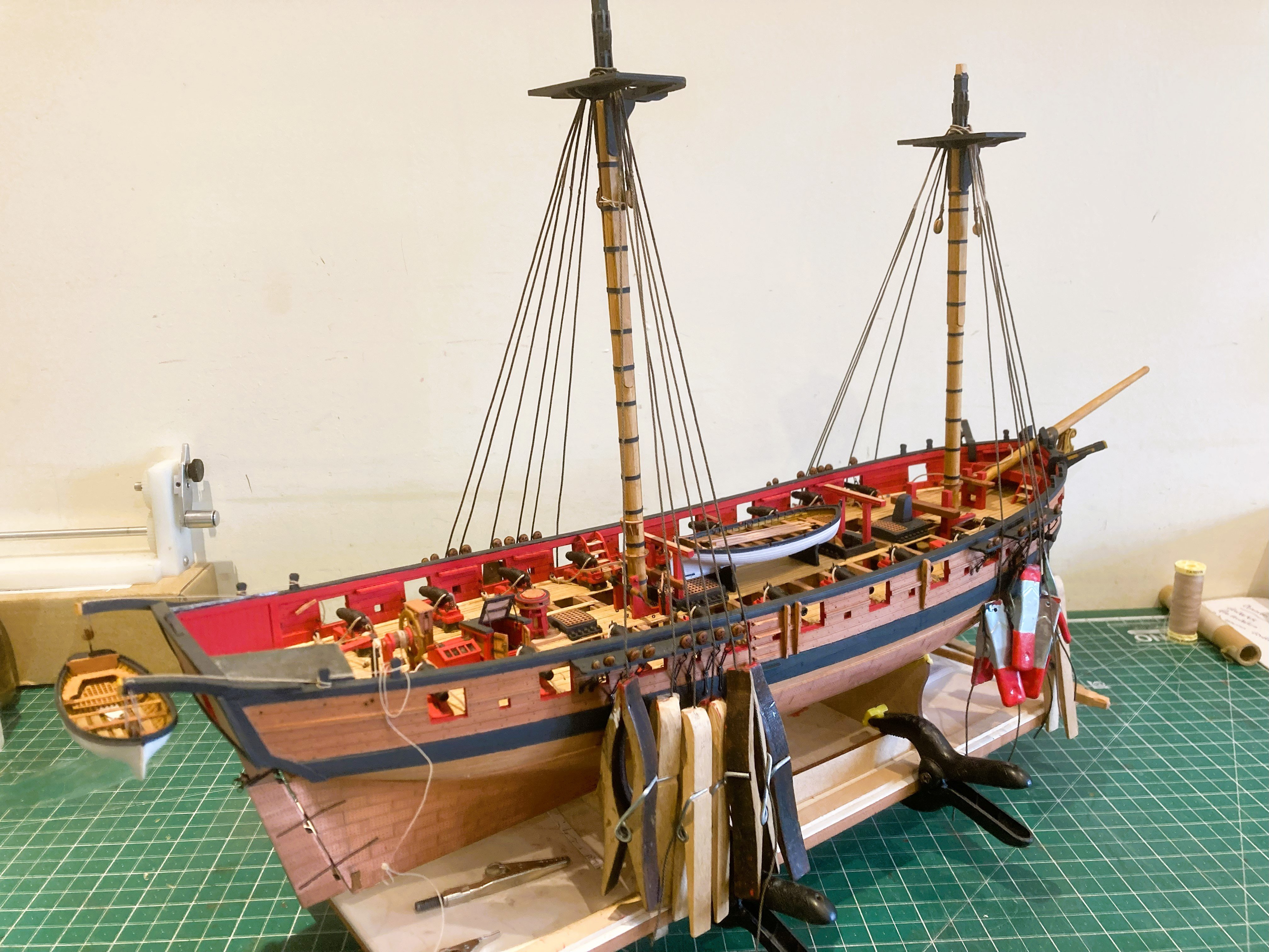
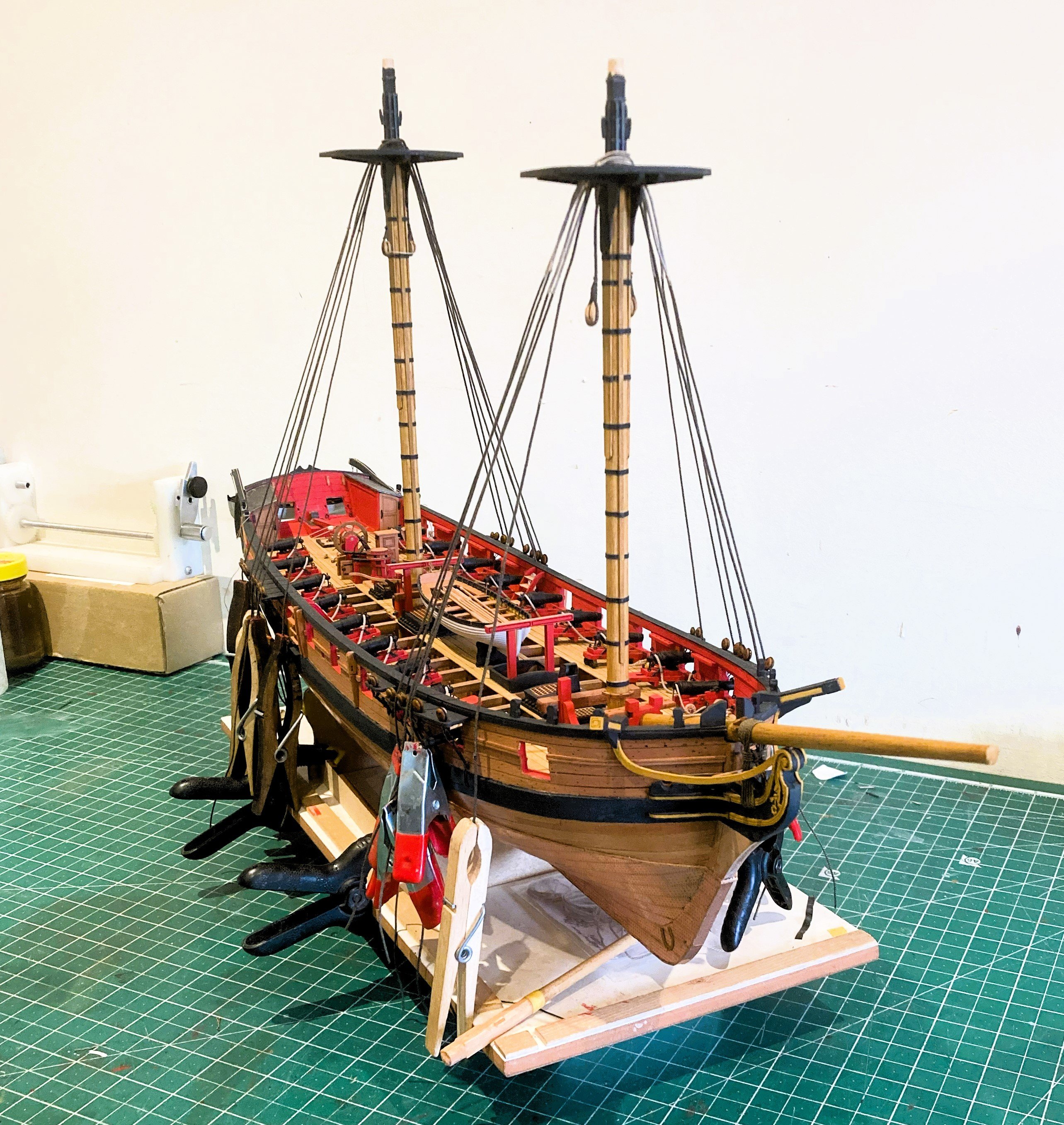
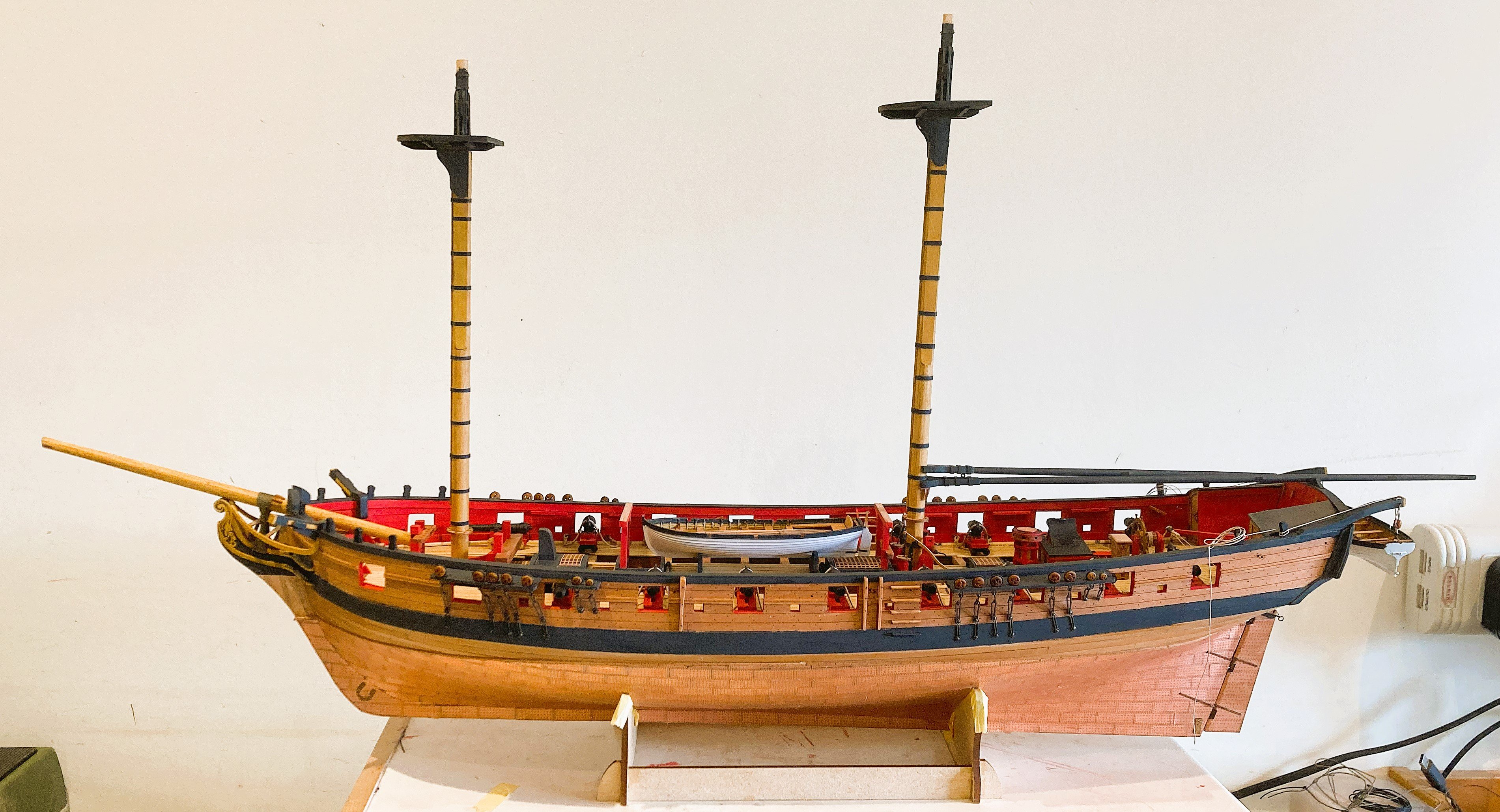
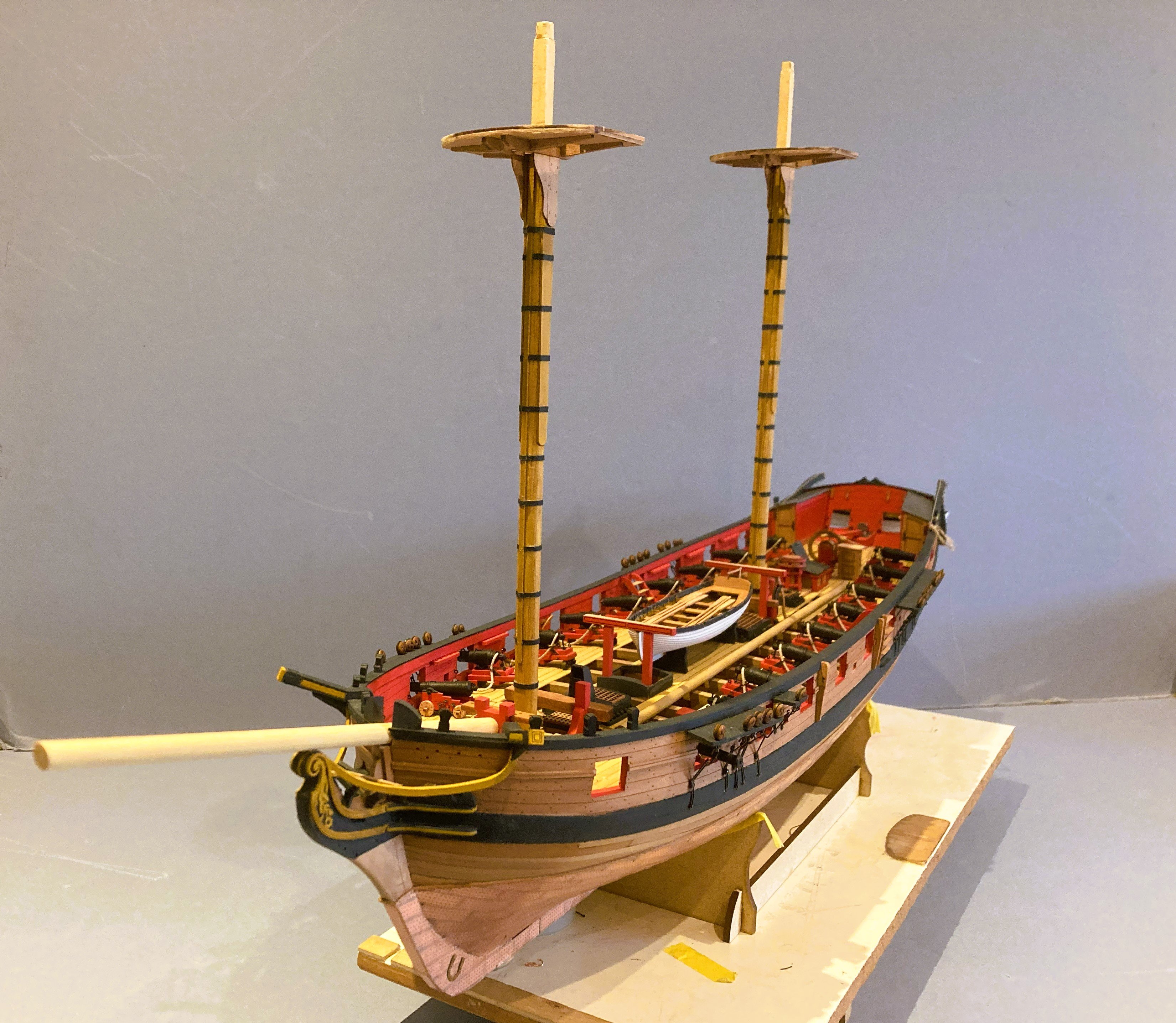
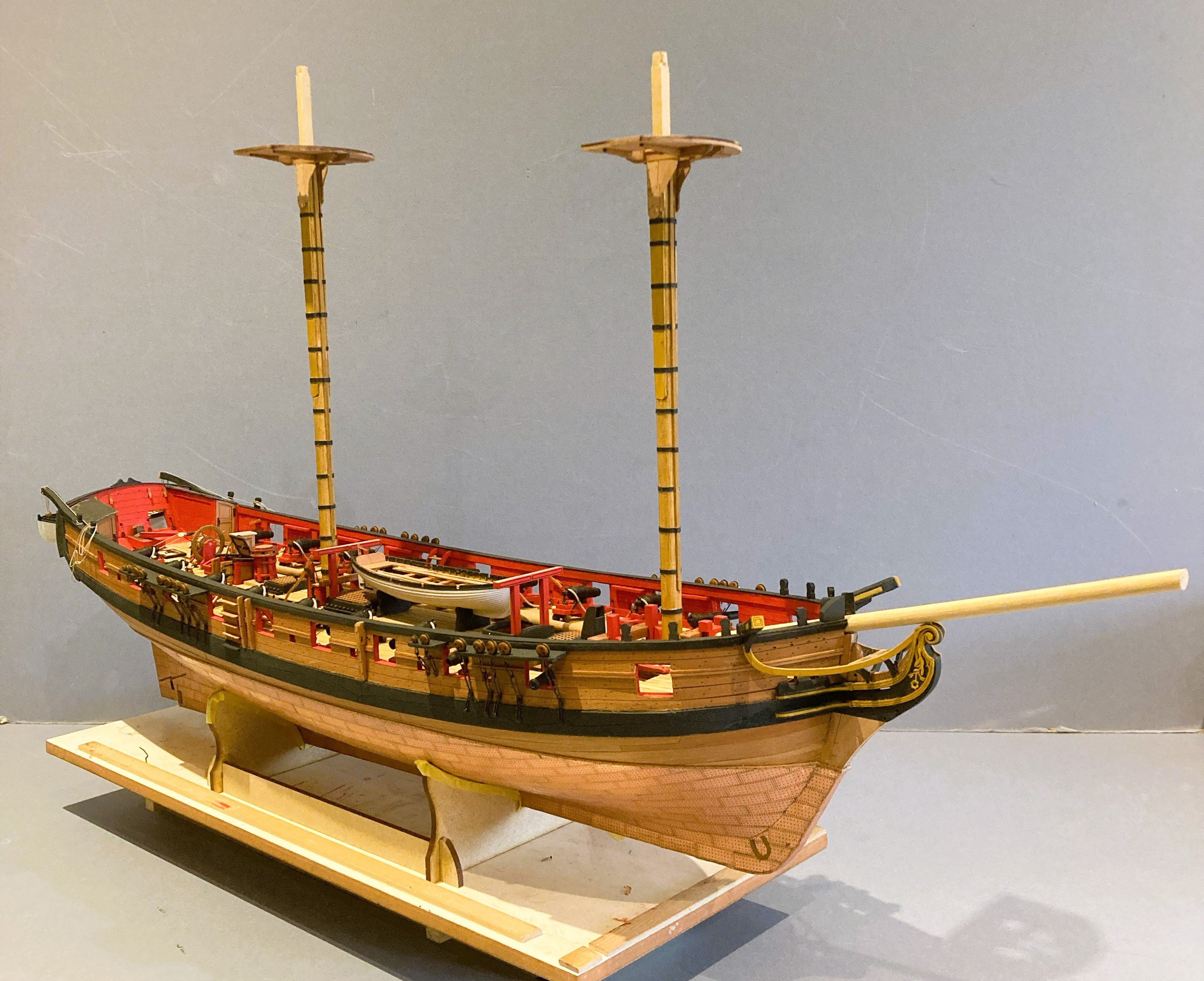
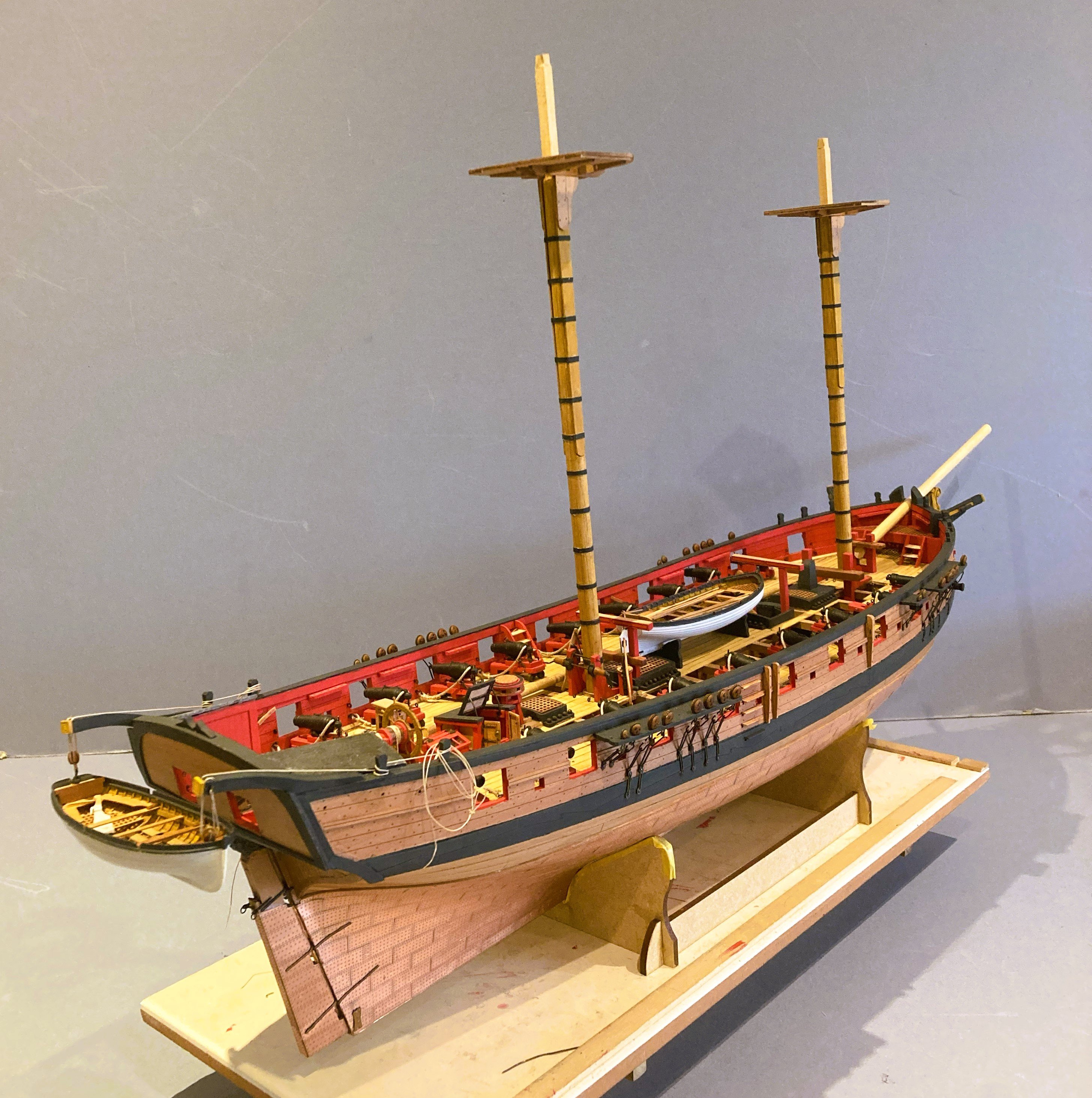
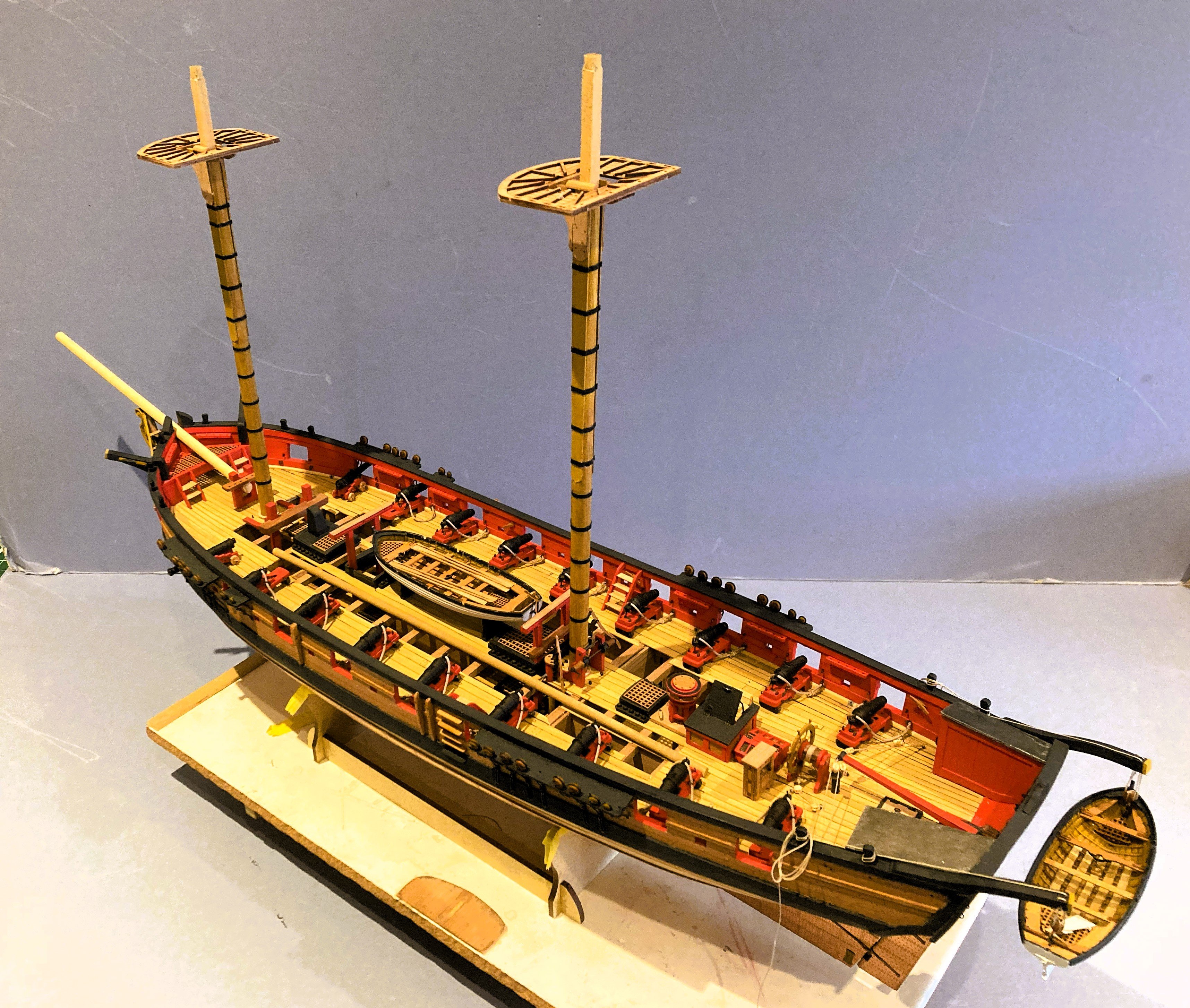
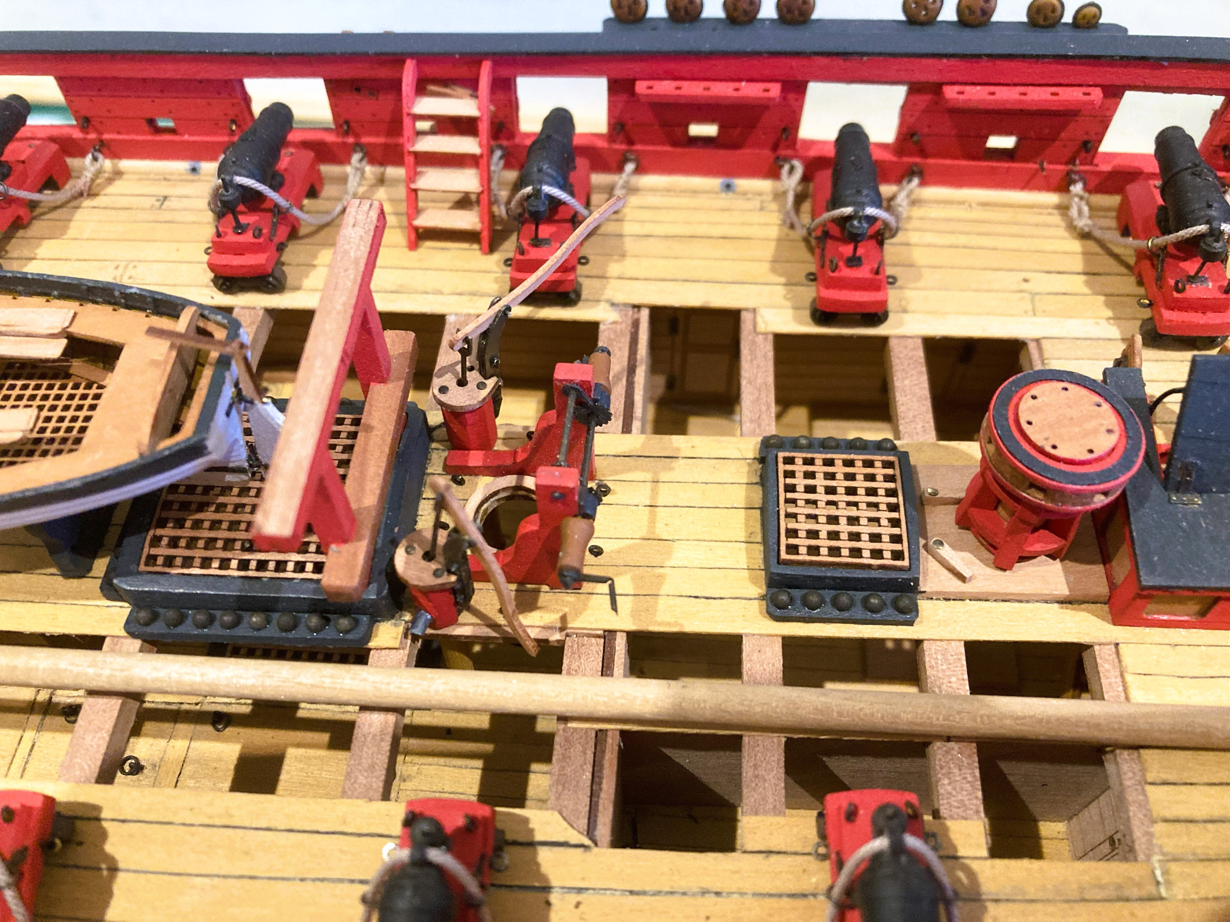
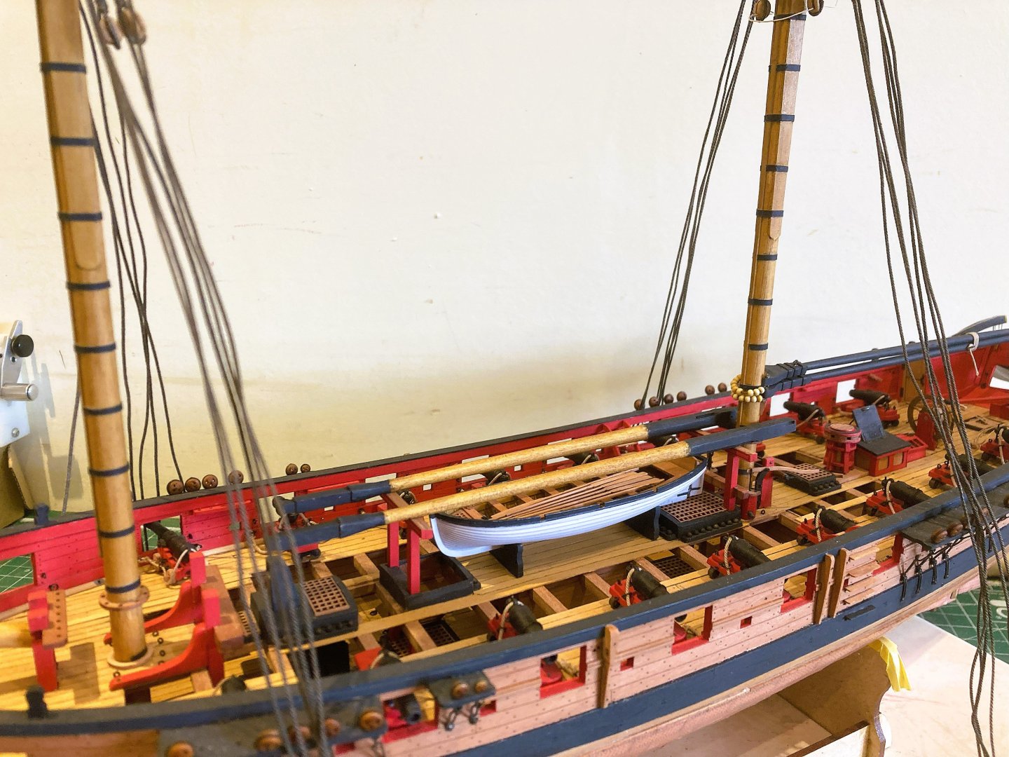
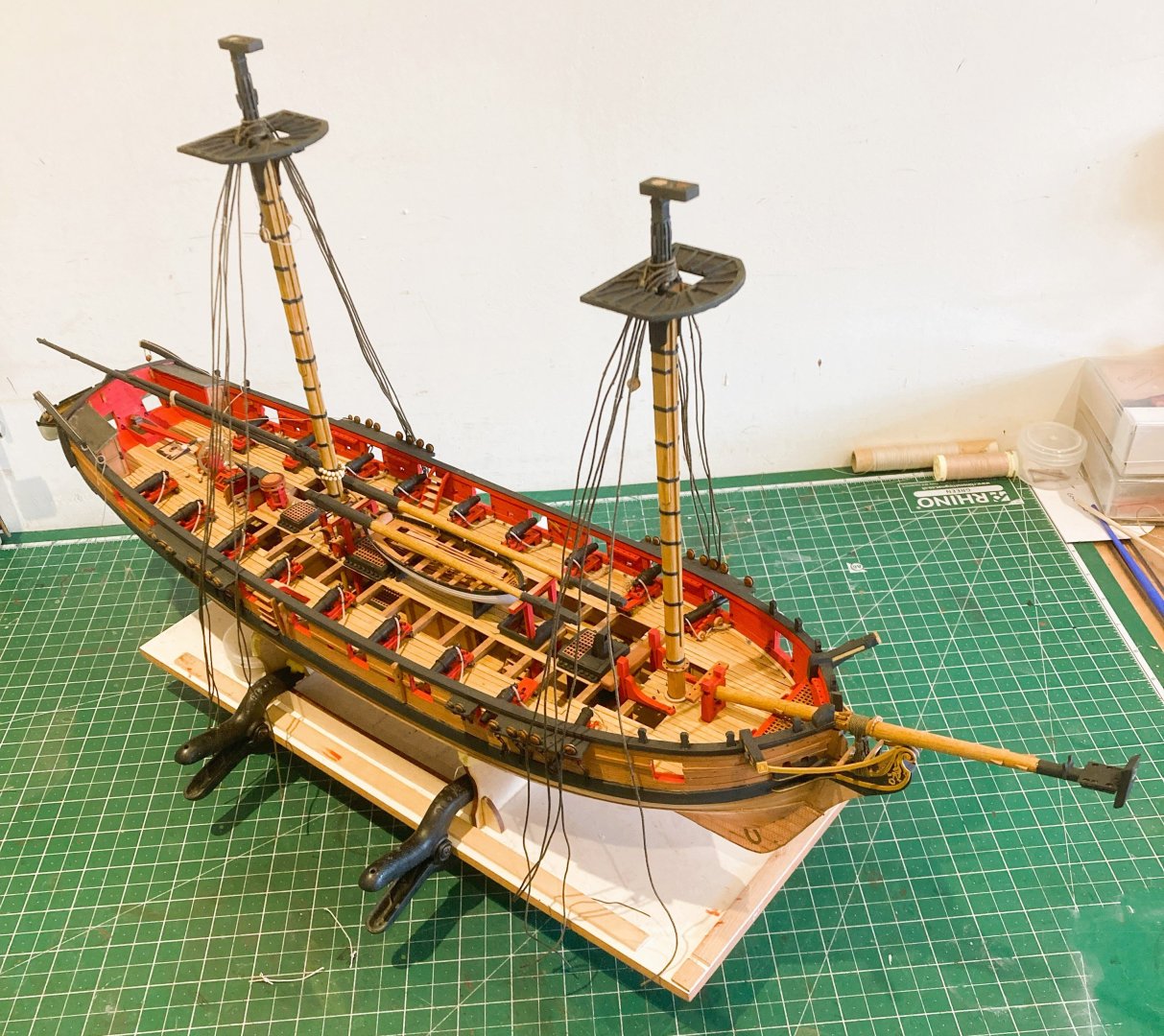
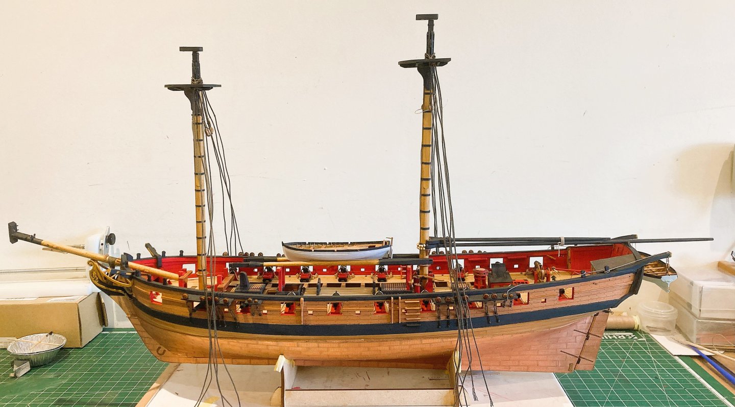
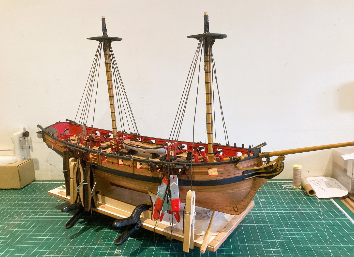
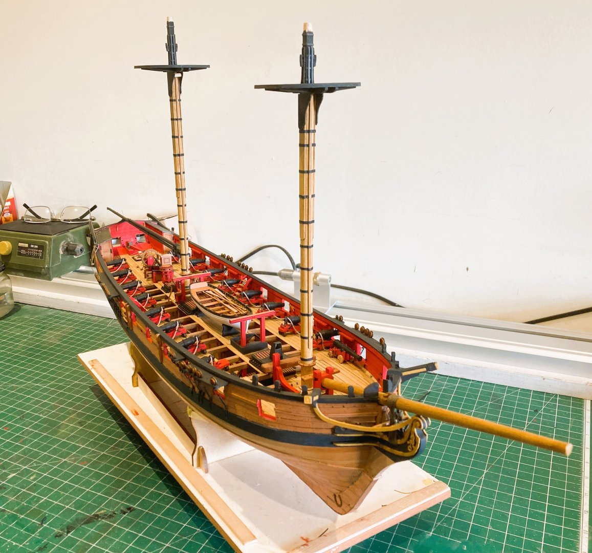
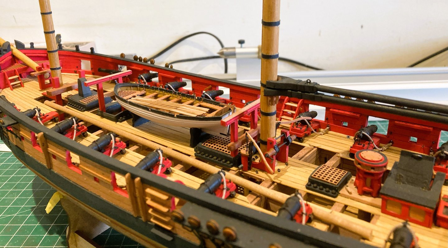
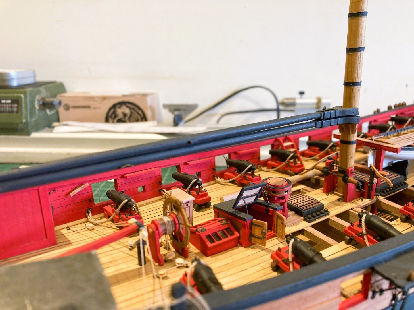
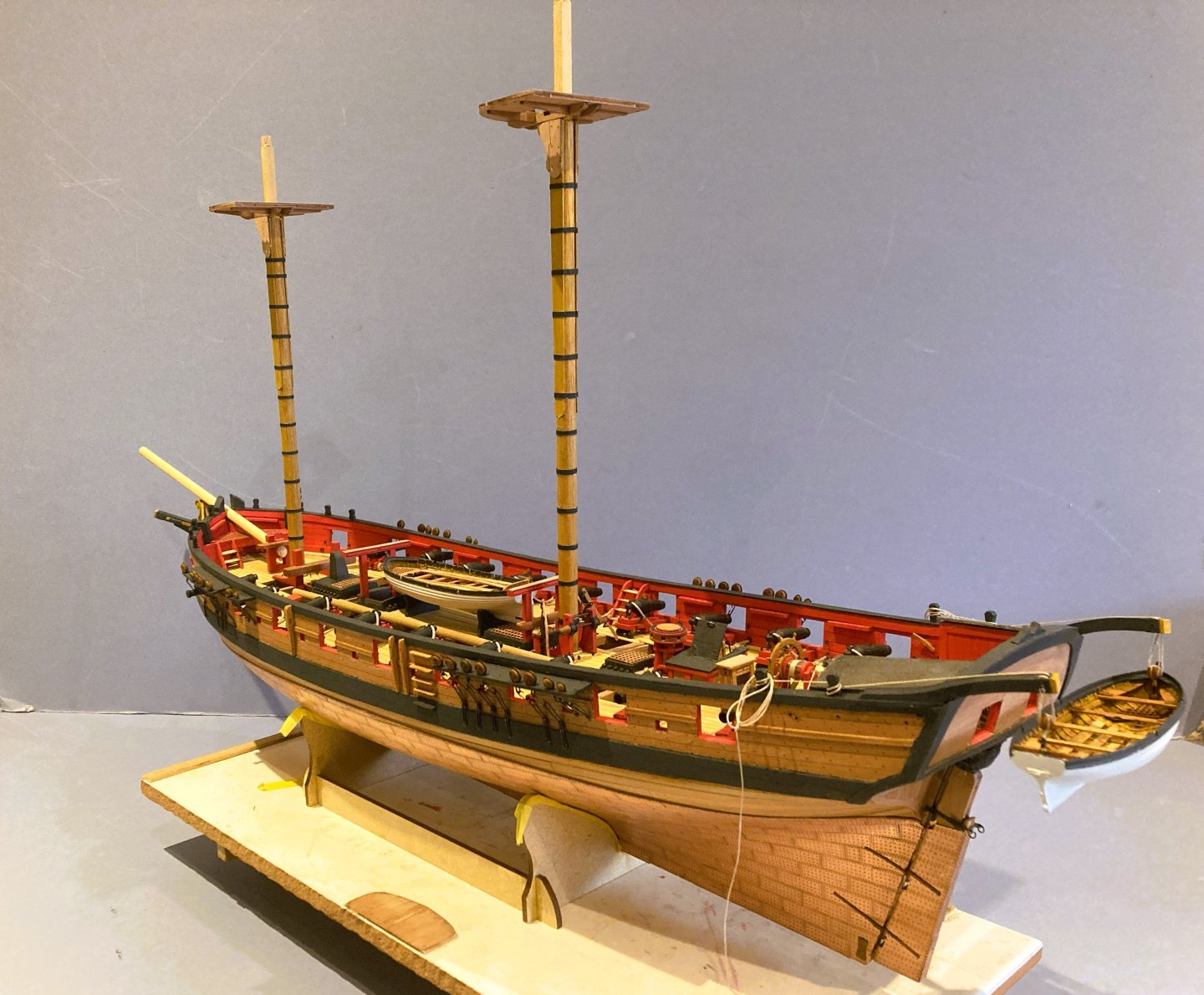
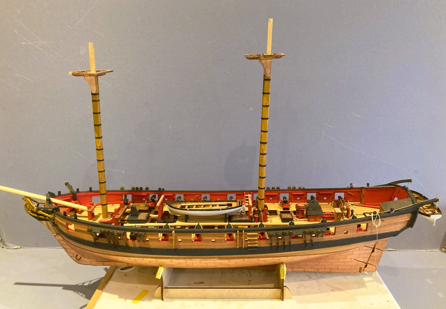
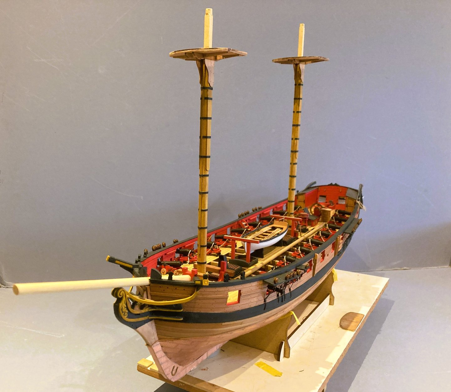
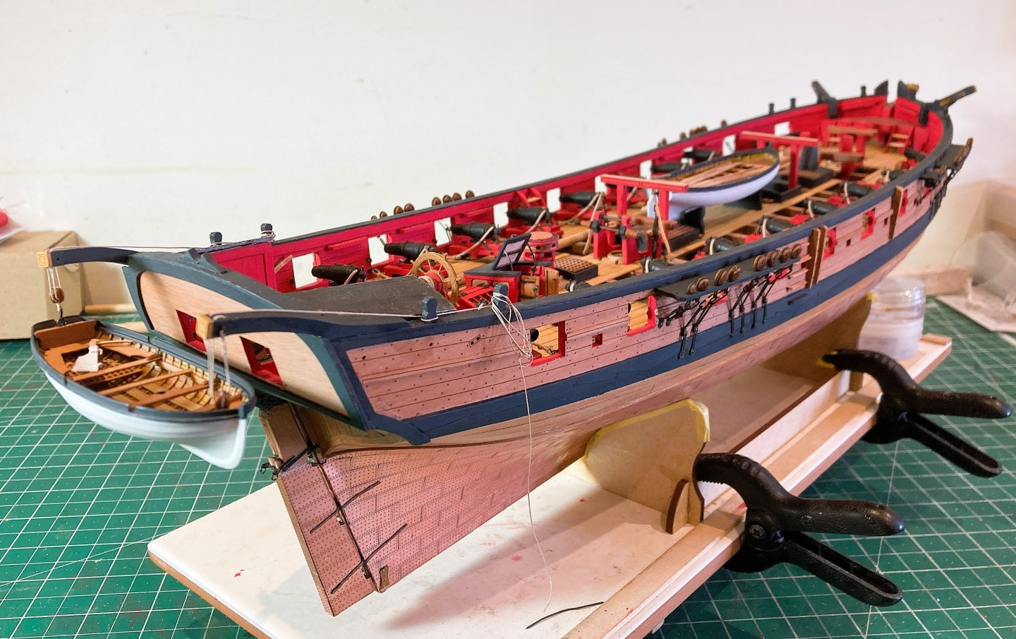
Post 81 A look around Harpy at this six month build stage, a very enjoyable experience overall. In my search for authenticity, there has been some frustration with detail queries, and some things still remain a mystery. Even so, she is shaping up into a fine model, Harpy is a worthy addition to Chris’s range. 4487a 4488a 4489a 4491a 4492a 4493a 4494a 4495a 4495a All the hull work bar some minor fittings, is now essentially complete, time to move onto the Masting. B.E. 25/05/2025


- 332 replies
-
- 25
-
-

-
- Harpy
- Vanguard Models
- (and 1 more)
-
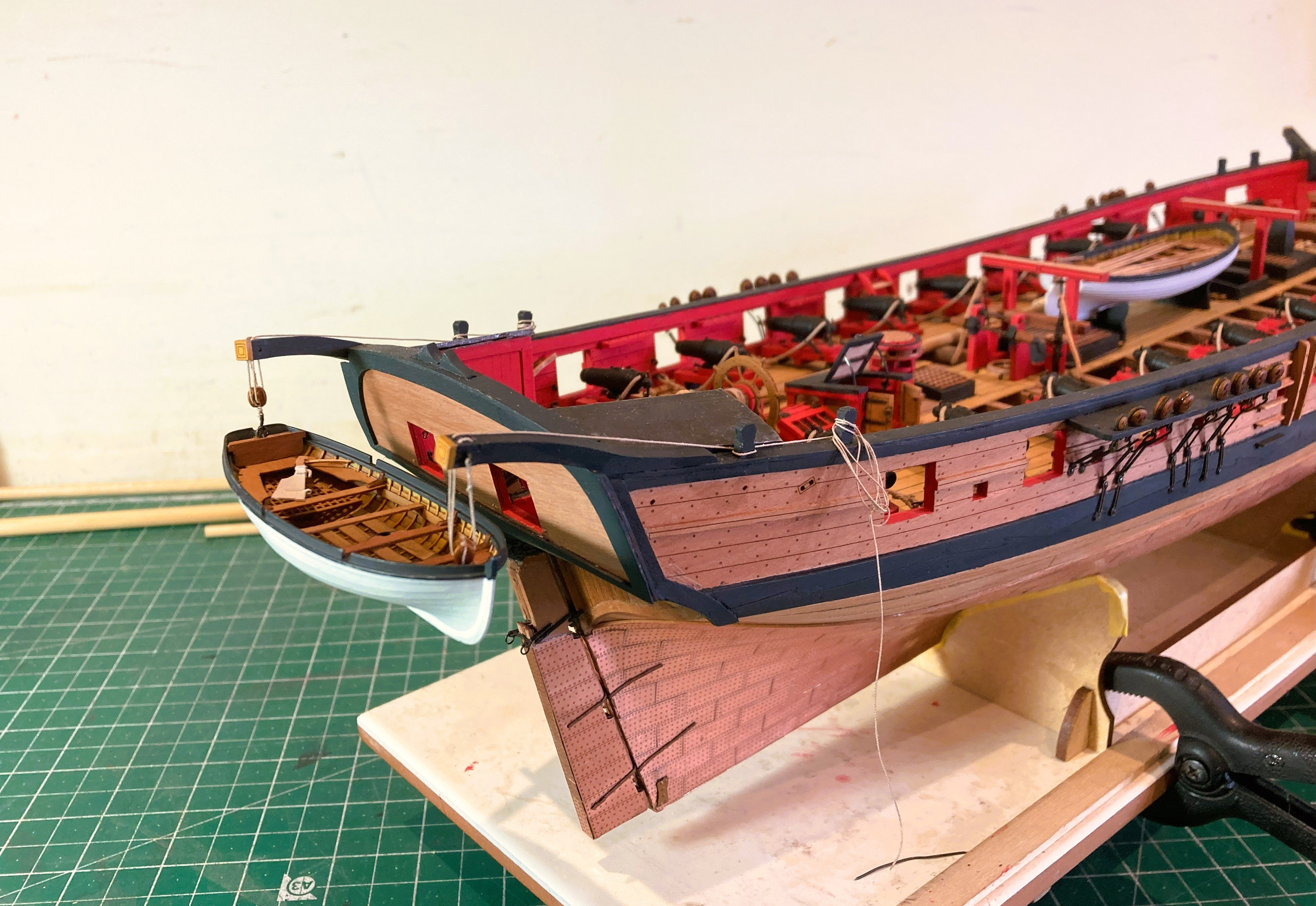
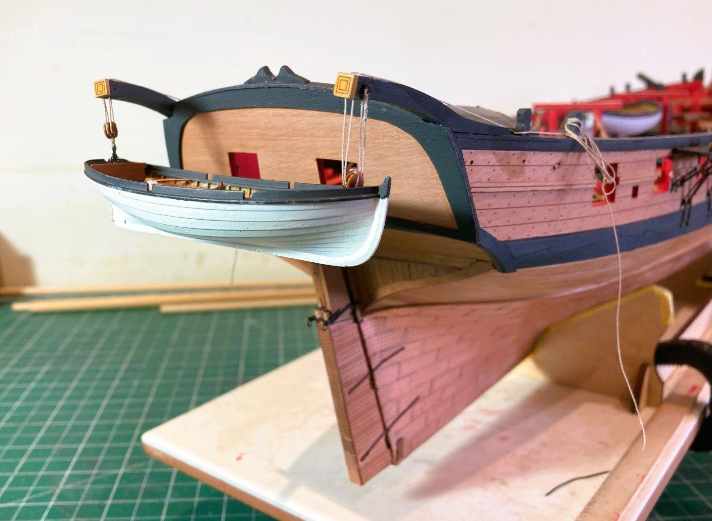
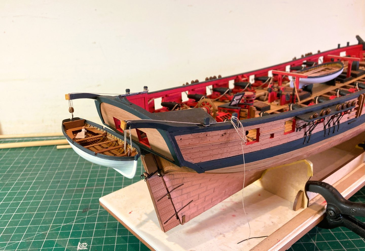
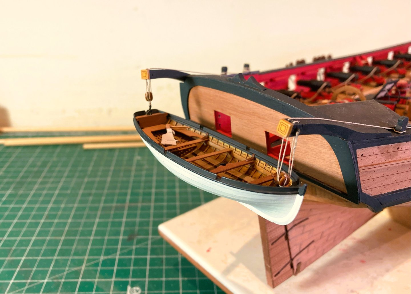
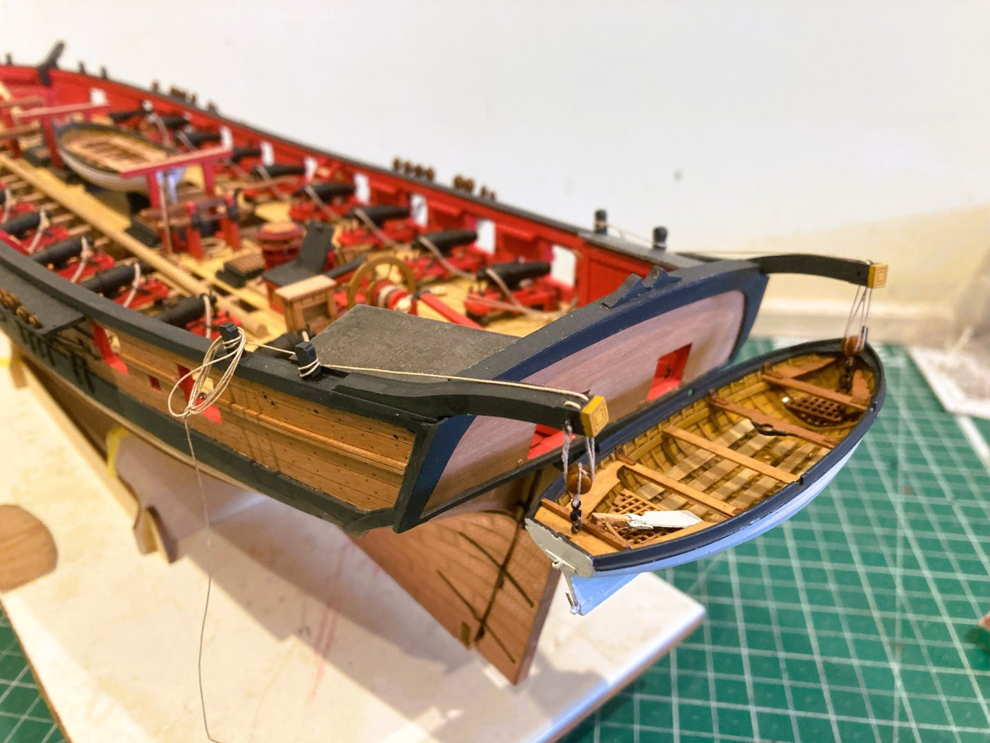
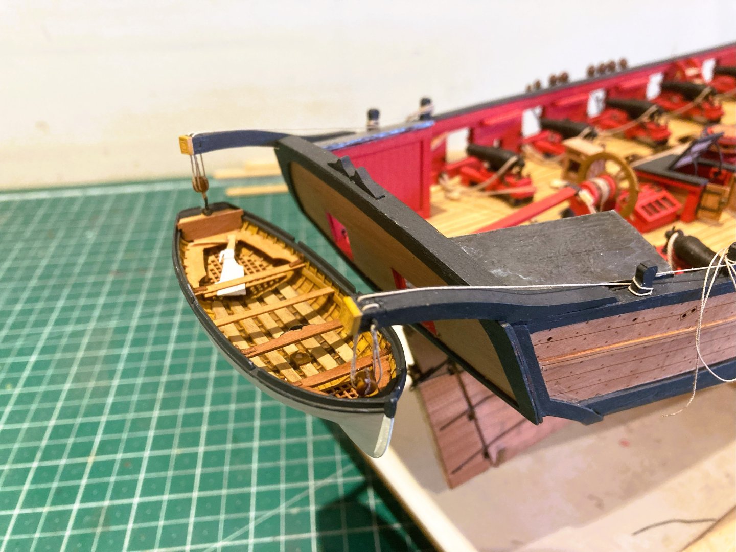
Post 80 Rigging the stern davits I used Syren 0.30mm line, 5/32” Double resin blocks, and 3mm plastic hooks. 0.1mm line is used for seizing. Chuck has produced an excellent method of block stropping, check out his pdf in the Traders and Dealers section. Quite a tricky business hanging the boat on the tackle hooks, it helps to apply a spot of glue to the ring to keep it in the vertical position. 4466a The handling during the attachment has rubbed some of the paint from the gunwales, so the boat will have to be removed at some some point for a touch -in. 4481 4471a 4483a 4472a 4473a Not quite sure yet how to belay the tackle falls. The kit plan simply shows them secured around the aftermost timberhead which sits against the cabin roof. Shot Garlands 4478a 4476a The shot garlands have been fitted, I used 2mm bearings rather than the kit supplied plastic versions. Belay pins Rather than fit the kit supplied brass etch pins I am waiting to see how Chuck's testing of 1:64 scale pins work out, I do hope they will be success. On my Harpy build they won’t be put under any stress as I’m not fitting the running rigging. Back to the masts… B.E. 27/05/2025
- 332 replies
-
- 19
-
-
- Harpy
- Vanguard Models
- (and 1 more)
-
Great start David, did you get the Boxwood from Original Marquetry in Bristol? the sizes look familiar. Cheers, B.E.
-
Thank you Chris, Ron, and Mark. Much of the credit goes to Chris who produced these little gems, the fittings stuff now available just gets better and better. B.E.
- 332 replies
-
- 3
-
-
- Harpy
- Vanguard Models
- (and 1 more)
-
She's looking wonderful, excellent work Chris, well done. B.E.
- 38 replies
-
- 4
-
-
-
- Alert
- Vanguard Models
- (and 1 more)
-
Very nice work, well done. 👍 B.E.