.JPG.ca33079f5815b861e67b9c2cccd37982.JPG)

Blue Ensign
-
Posts
4,570 -
Joined
-
Last visited
Content Type
Profiles
Forums
Gallery
Events
Everything posted by Blue Ensign
-
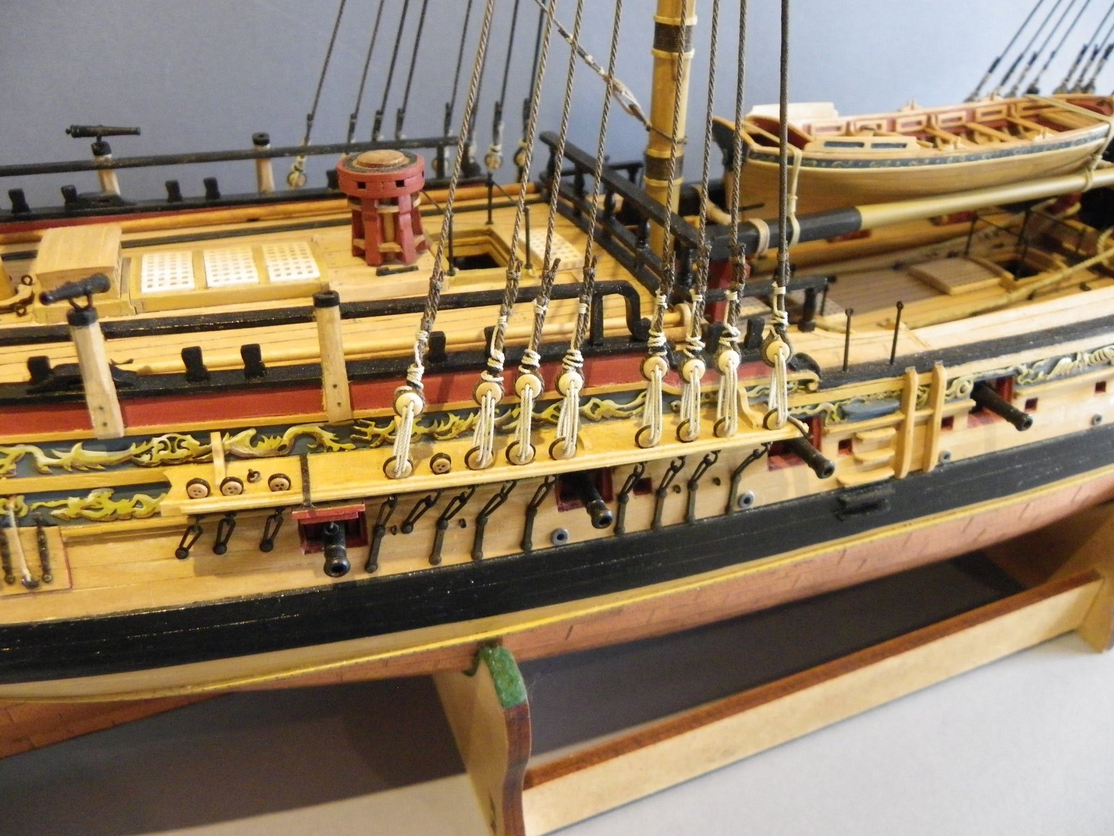
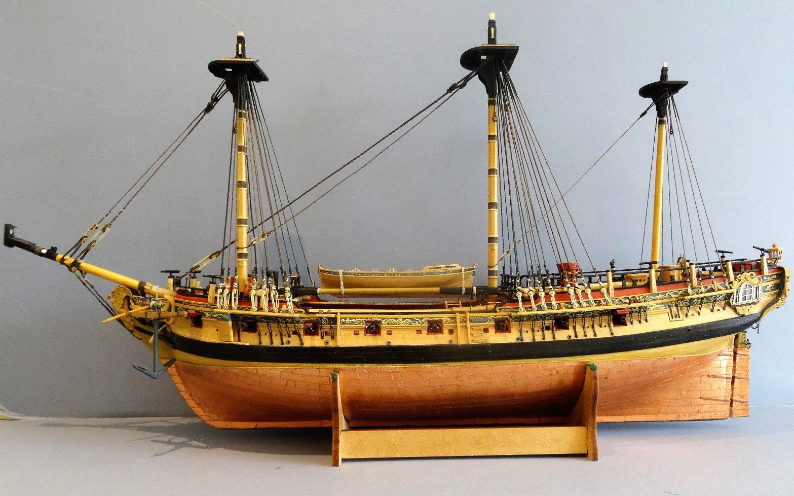
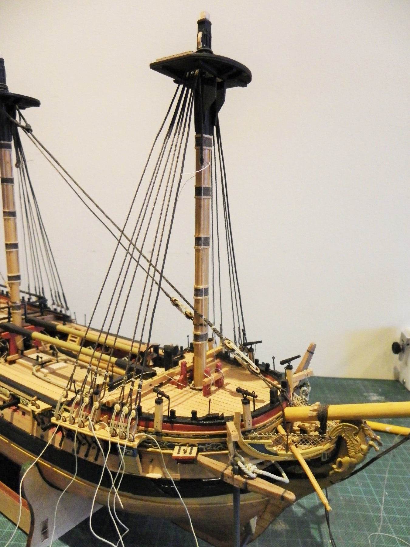
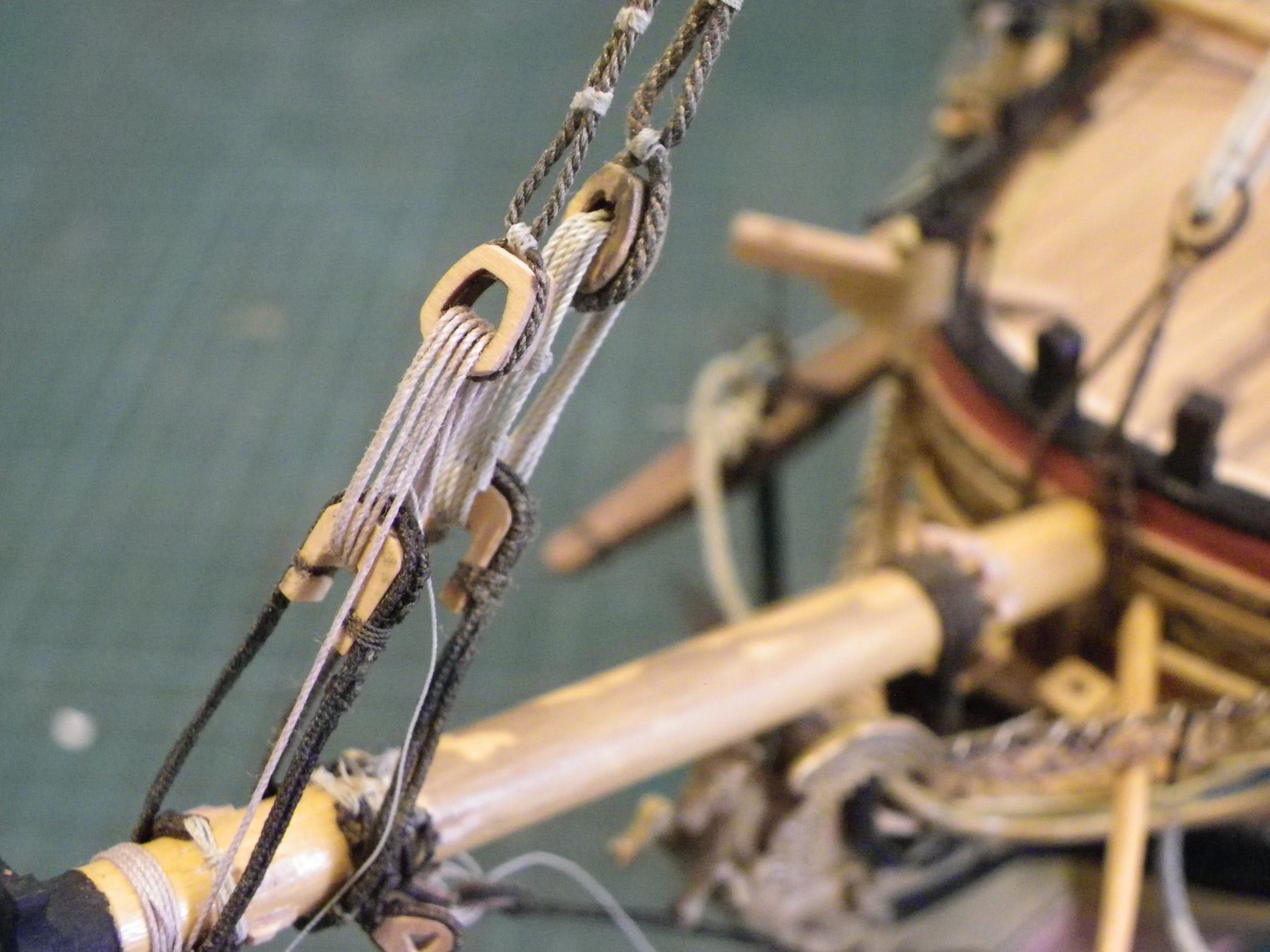
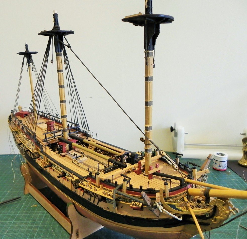
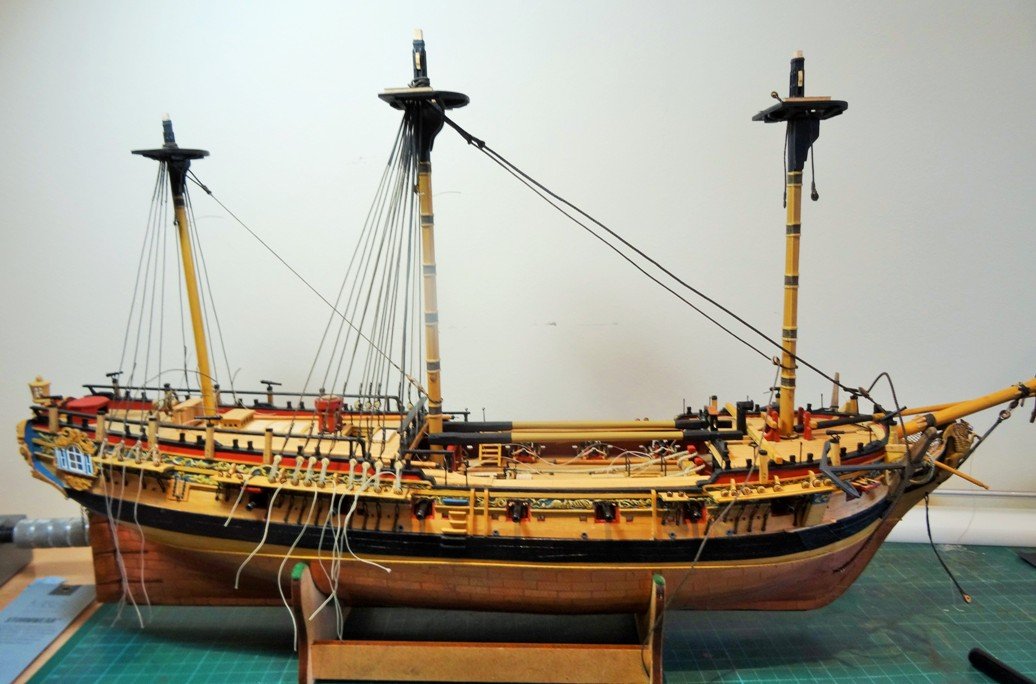
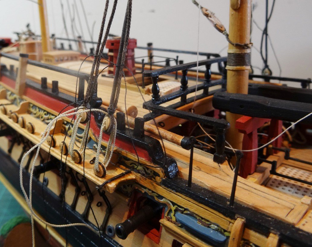
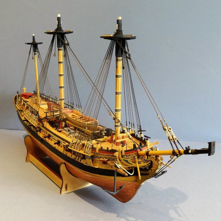
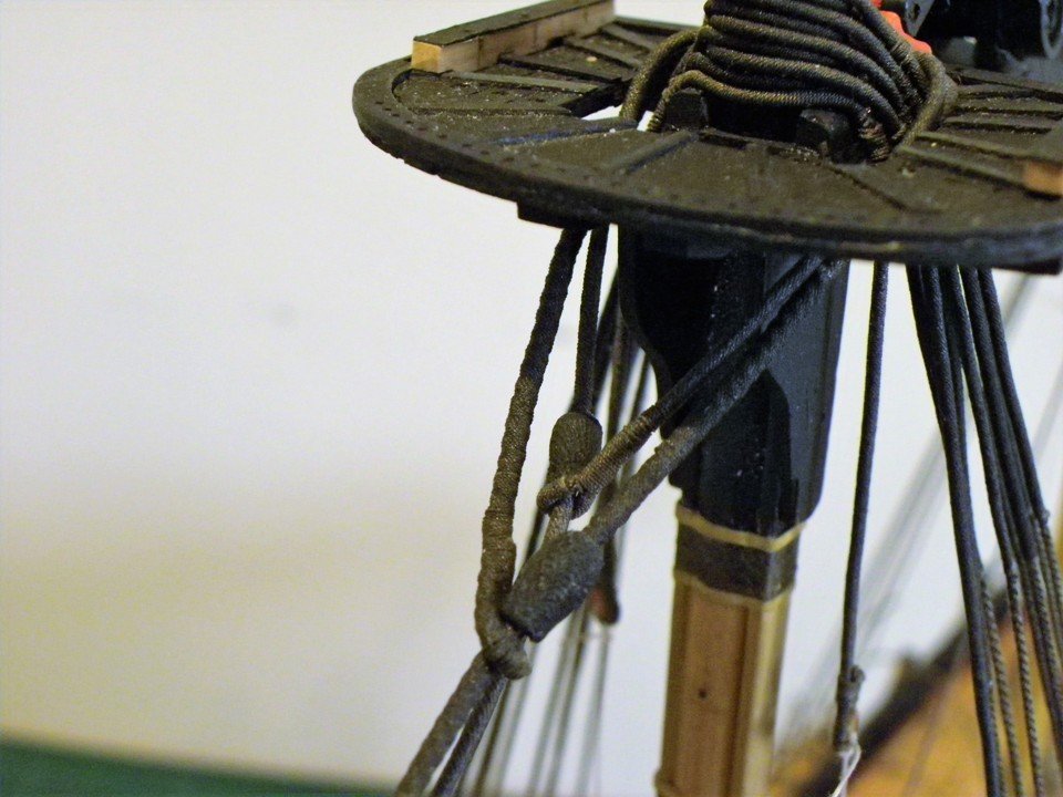
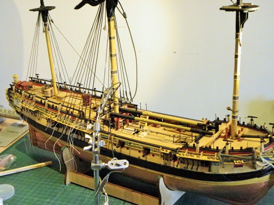
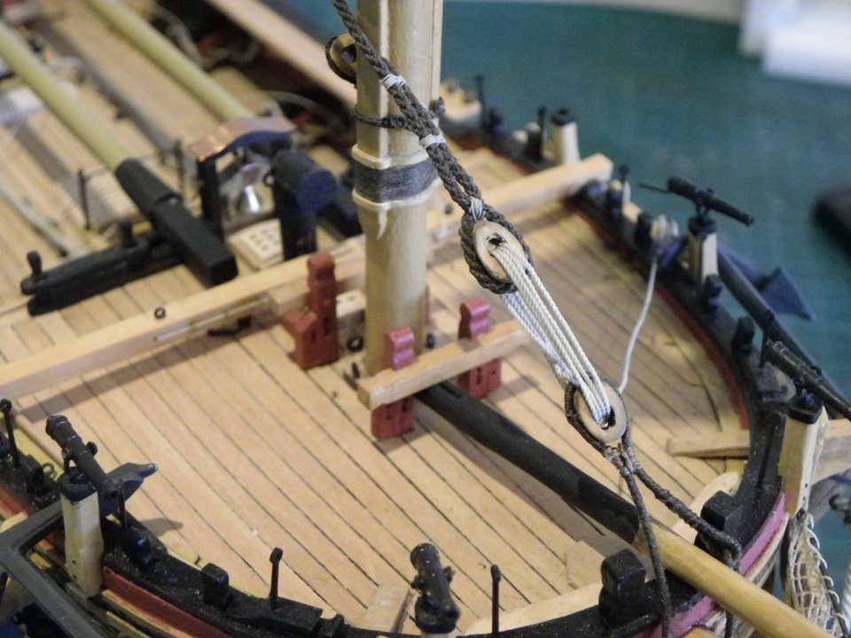
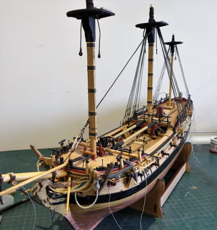
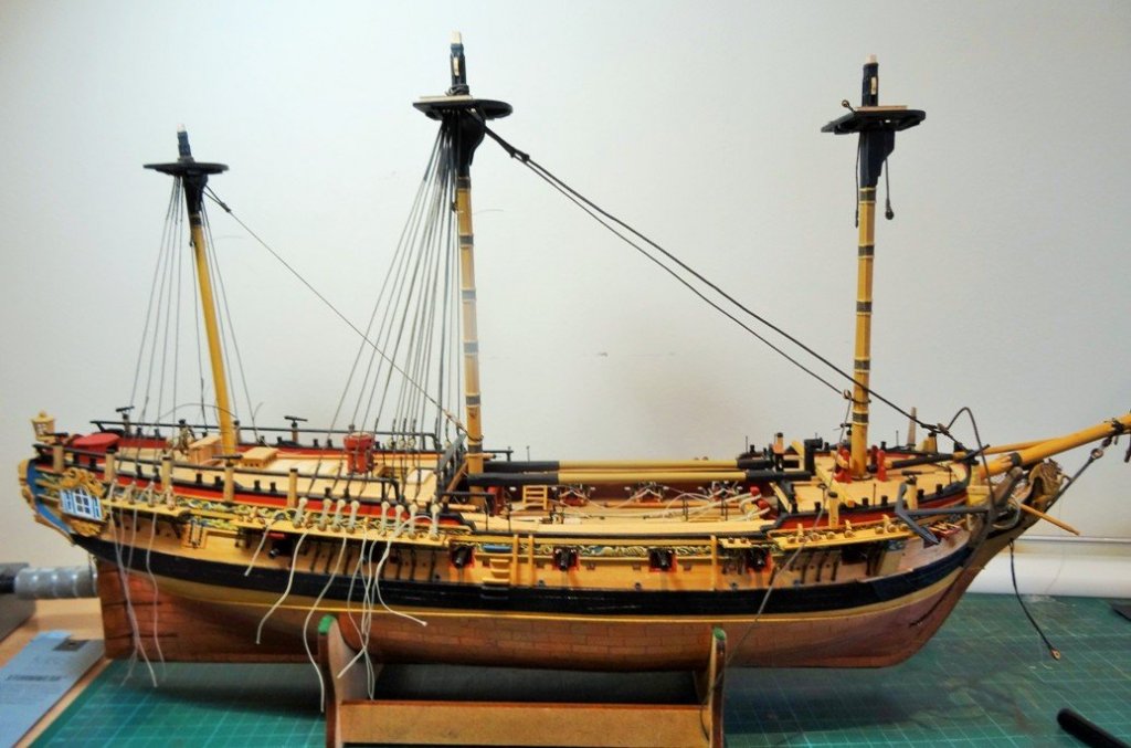
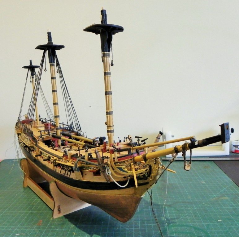
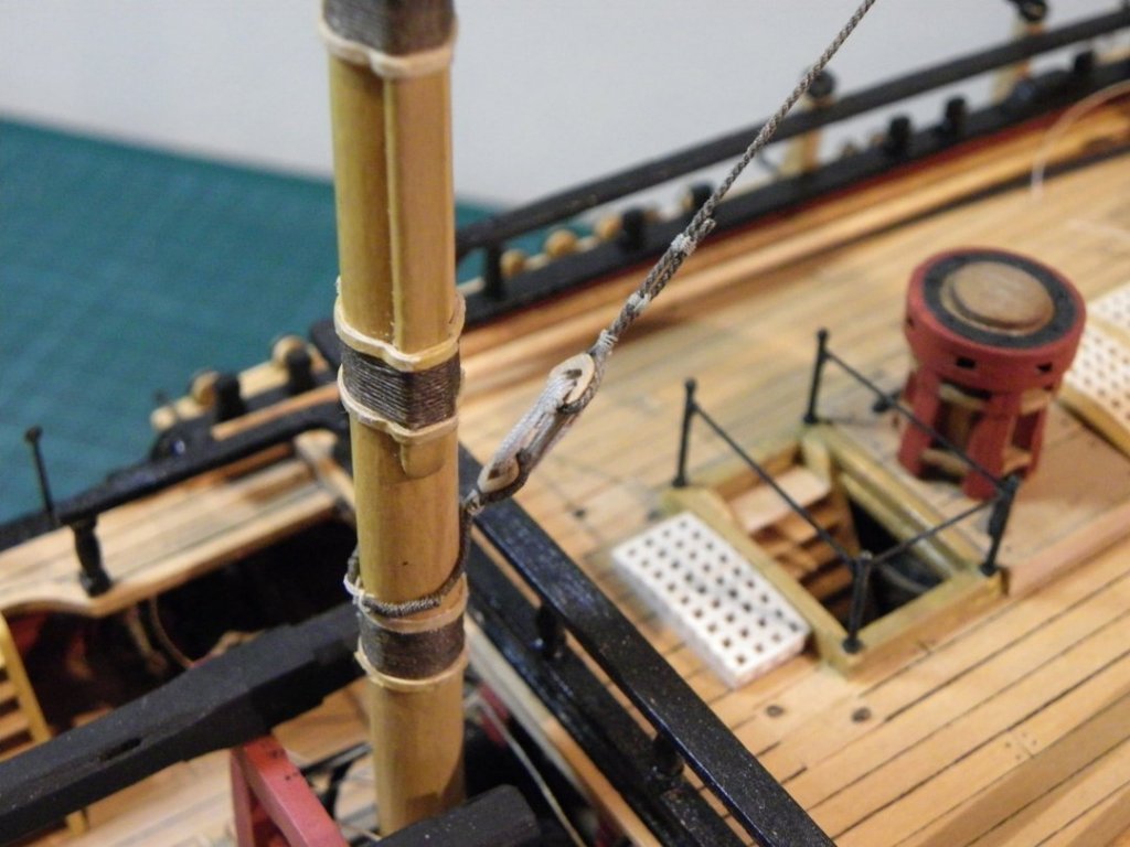
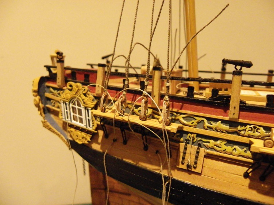
 The lower shrouds have now been tidied up and the lanyards secured. Only diluted pva has been used here to allow removal if required. The Bobstays have also been attached by their lanyards using 0.25mm ø Morope. A few photo's to mark completion of this stage of the build which is now in its seventh year, although I hasten to add that there have been long intervals when little was done to progress the build. I will next be looking at the Futtock staves and ratlines. B.E.


- 366 replies
-
- 2
-

-
- pegasus
- victory models
- (and 2 more)
-
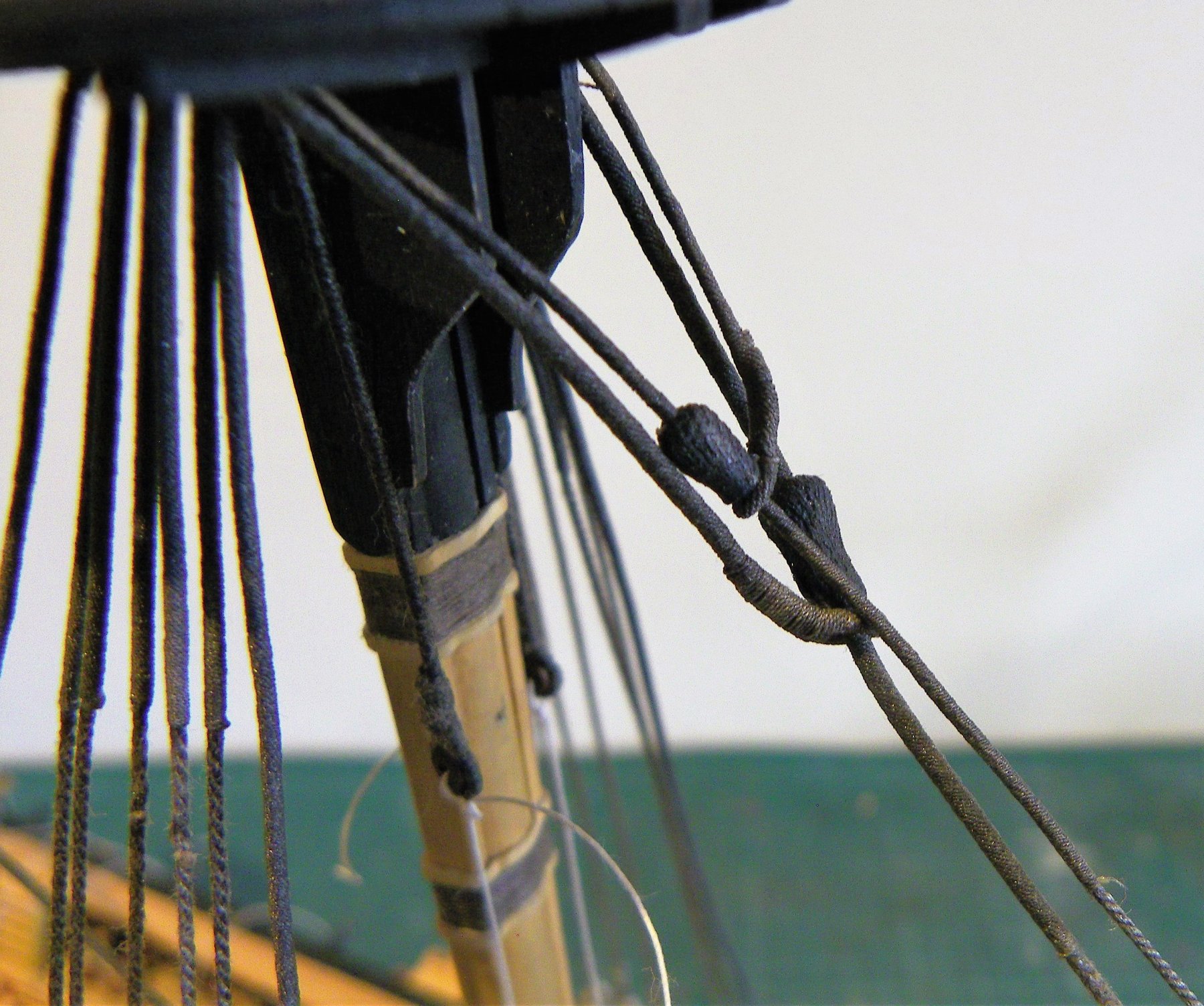
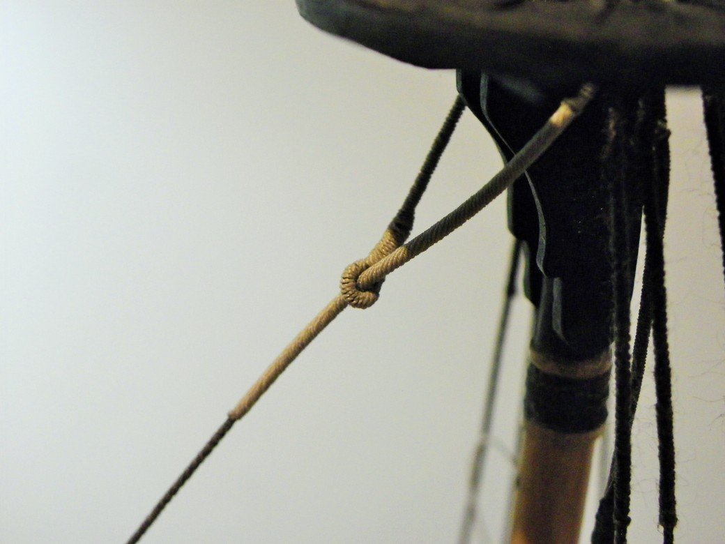
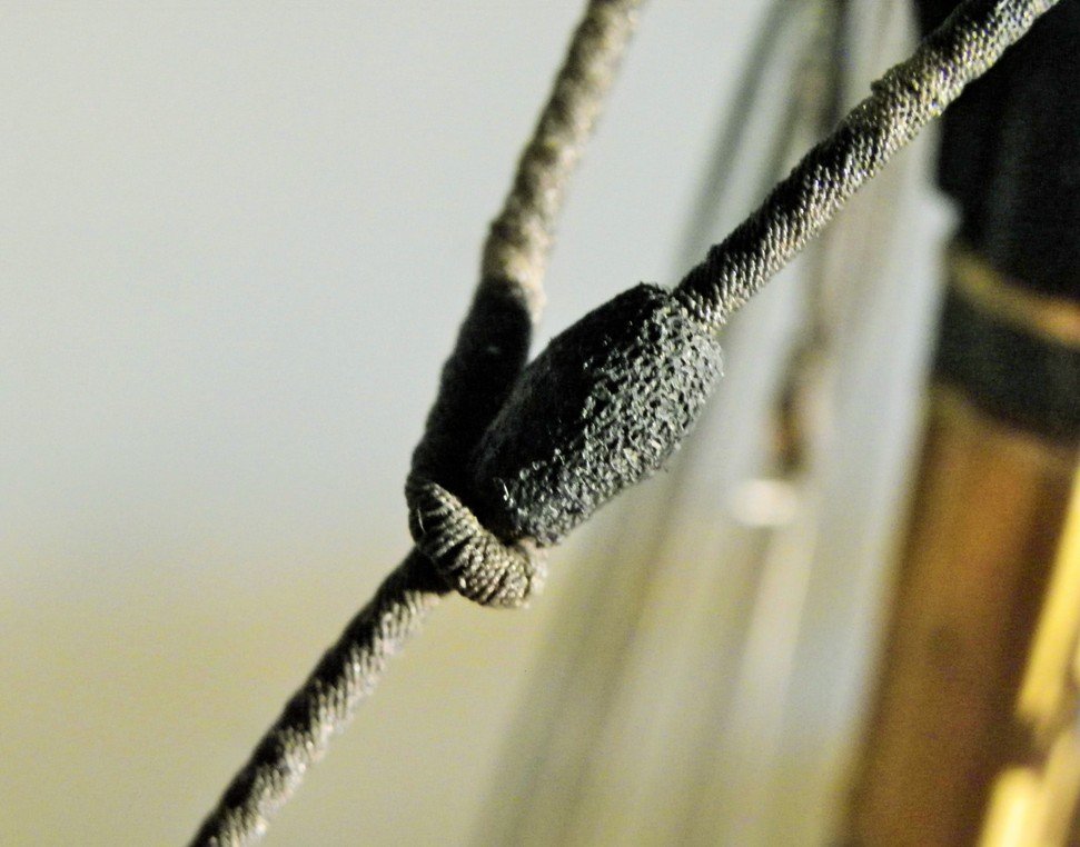
The Fore Shrouds 7" circumference line (0.88mmø) as per the Main shrouds is used. 0.4mm ø Morope for the Lanyards, and 0.1mm for the seizings. Configuration of shrouds. These consist of three pairs each side plus a single spliced making seven shrouds each side. Both the kit and the ffm plan follow the same arrangement. The ffm however suggests that the 'single' spliced shroud should go over the masthead first after the Burton Pendants, whereas the kit plan indicates the 'singles' are last over the Masthead, although they show a simplified seizing around the mast head rather than a cut splice. My understanding is that singles were called 'swifters' and were always last over the masthead with a cut splice, this is the arrangement I have followed. Fore shrouds completed but yet to be made taut by securing the lanyards. Fore Stay 9½" circ cable = 1.2mm ø line -I am using Syren 1.14mm line. 13" closed heart = 5.2mm. lanyard 3½" (0.44mmø) Mouse = 3.42mm ø L =1.25mm The Fore and Fore Preventer stay collars were made and attached to the Bowsprit a fair way back in the build. To recap these are open hearts, not the closed versions as supplied with the kit. They are scratch built of boxwood. In the intervening time Chuck has produced some fine 5.5mm and 7mm hearts both open and closed which would have saved me the trouble. Close-up of the Fore stay mouse. and the secured heart and lanyard. Fore Preventer Stay 6" circ cable = 0.76mmø 10" closed heart = 3.96mm. Lanyard 2½" circ (0.31mmø) Both these stays are made as the Mainmast versions. Mouse = 2.28mmø L = 0.79mm For this stay I have used Morope 0.80mm ø line, and one of Chuck's 7mm hearts reduced in size a little. Fore preventer mouse. Lanyard fitted but yet to be secured. The lower standing rigging now all in place, but requires some tidying up. B.E.


- 366 replies
-
- 2
-
-
- pegasus
- victory models
- (and 2 more)
-
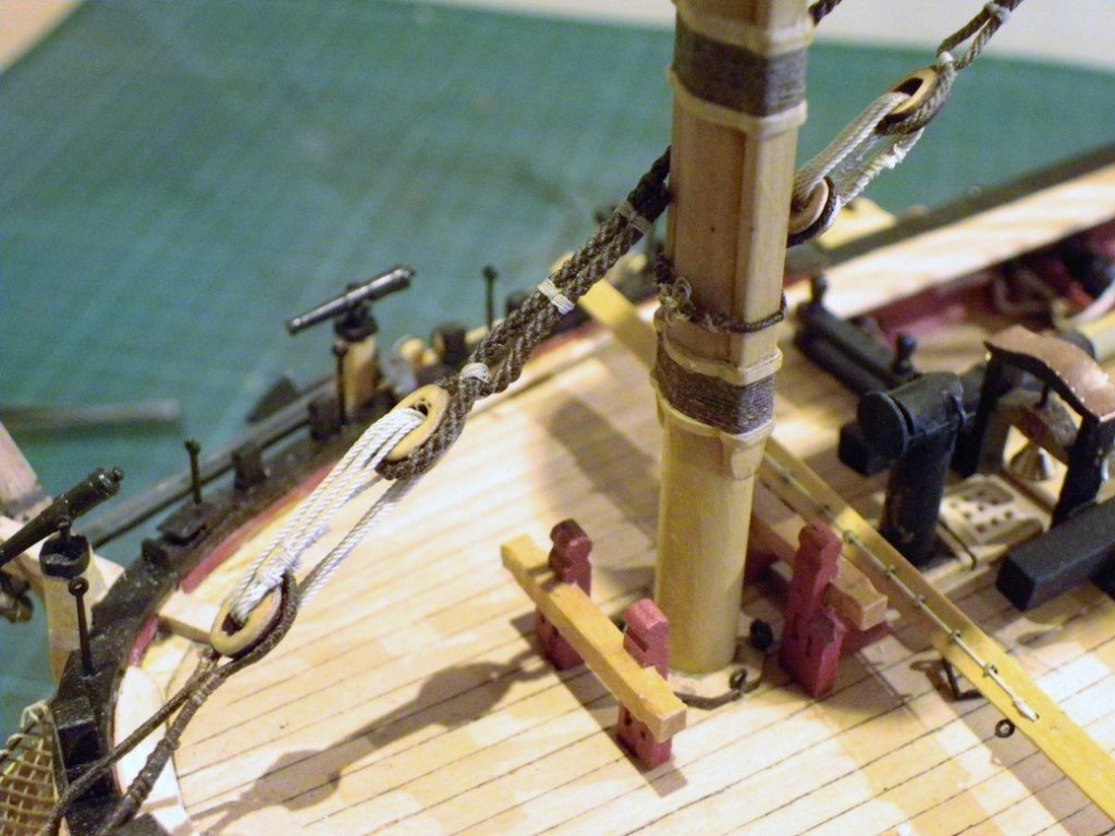
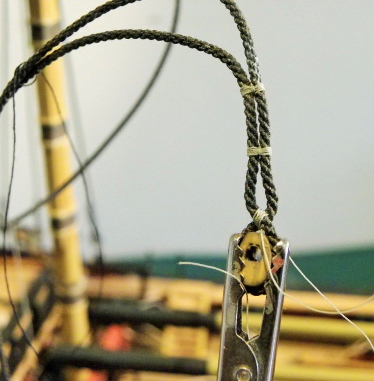
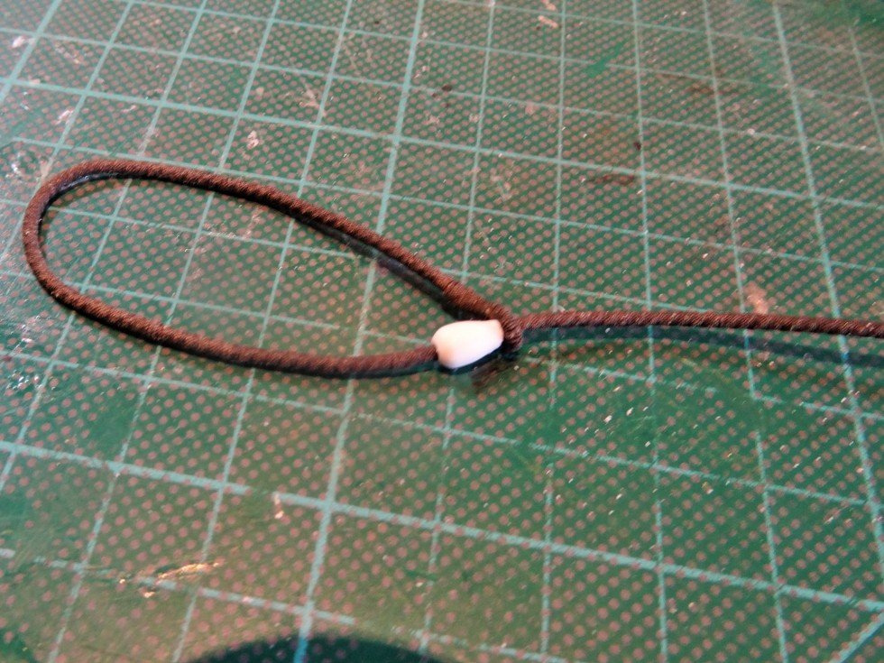
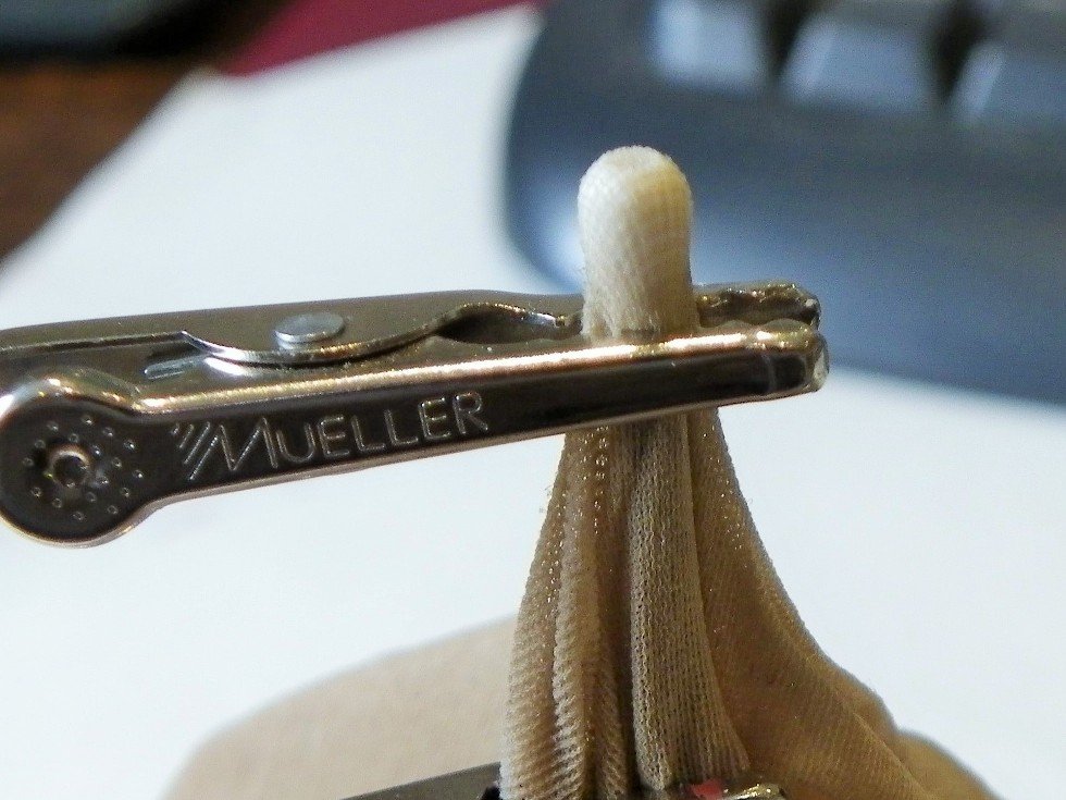
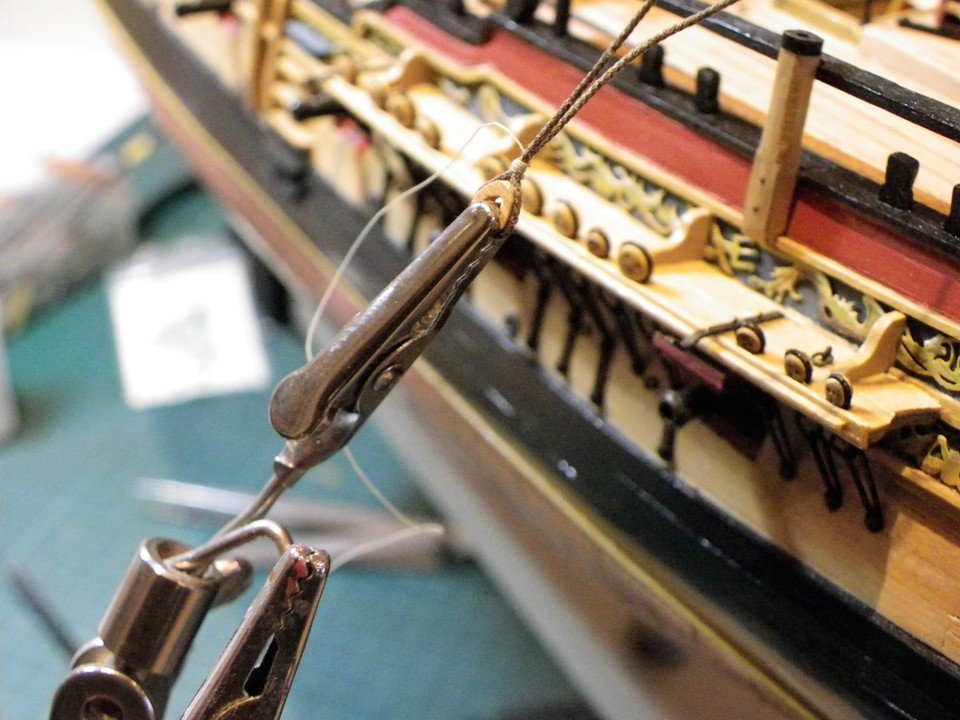
Attaching the Main Preventer Stay Main Preventer Stay Heart 11" (4.4mm) lanyard 3" (0.38mm)seizings 1.0mm. The Preventer has already been prepared complete with mouse so there only remains to fit it over the masthead and down thro' the Main Stay. The closed heart is attached as on the Main Stay. I have used a Syren* 5.5mm heart which is only a fraction oversize but importantly looks right. *These hearts supplied by Chuck really are an excellent idea, and save a lot of fiddling around. 0.4mm Morope is used for the Lanyard, which in respect of the Preventer Stay needs to be tied off because the job would get far more difficult once the Fore Shrouds are in place. I find tying off the lanyard quite tricky as the free end should be lashed to the adjacent turn to finish. It is so tempting to expend the excess by turns around the middle of the lanyard set up, which is a far easier option. I use a small clamp to ensure that the Collar of the Preventer Stay doesn't ride up over the shrouds whilst I am fitting the lanyards. The completed lanyards. The seizings will be dyed but the lanyards will be left natural. I now need to prepare and fit the Fore Shrouds. Regards, B.E.

- 366 replies
-
- 3
-
-
- pegasus
- victory models
- (and 2 more)
-
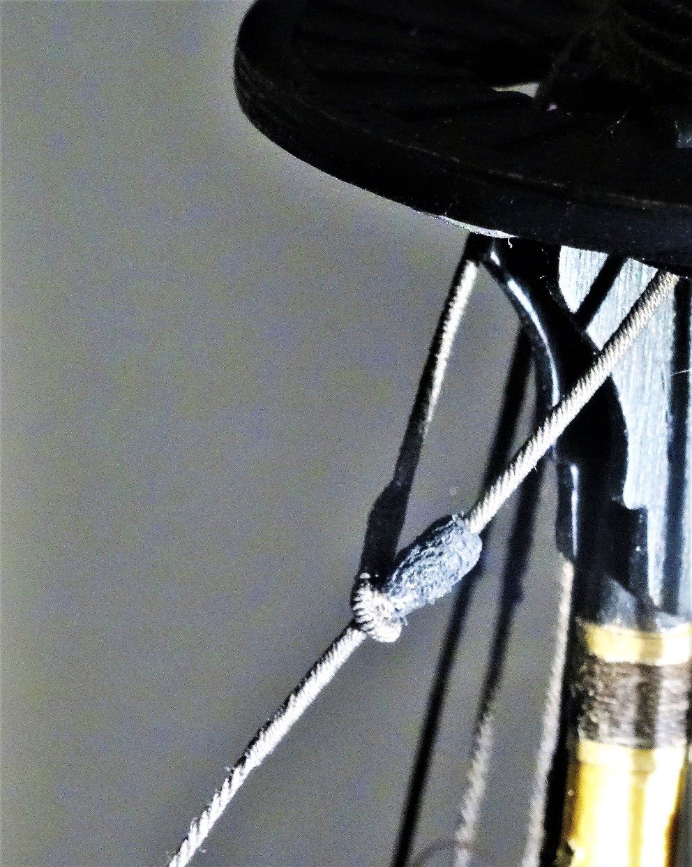
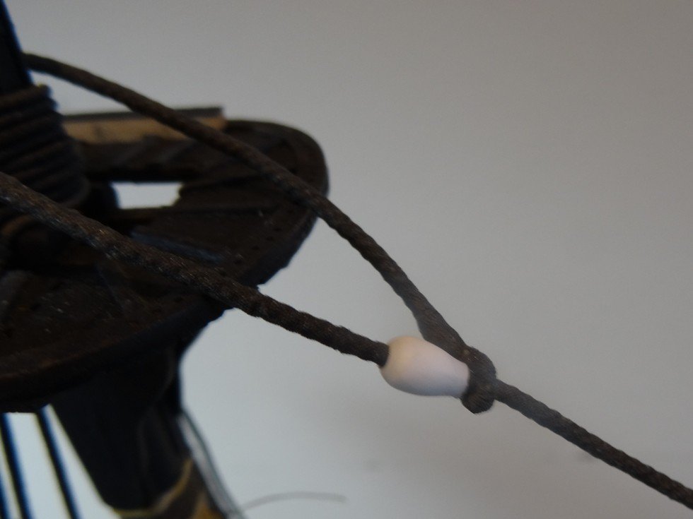
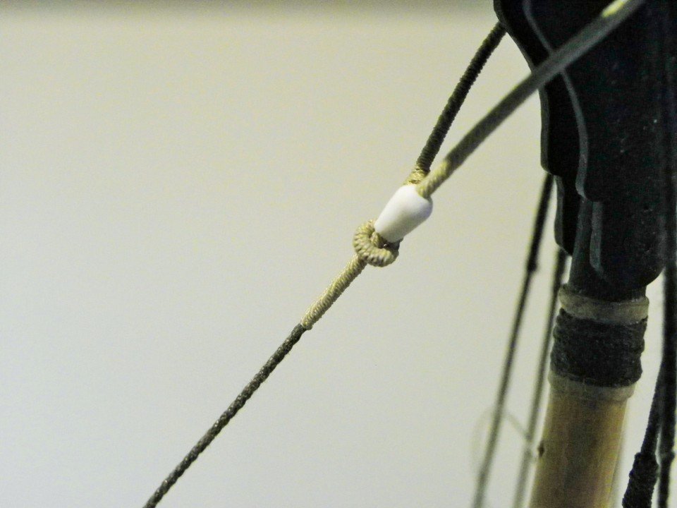
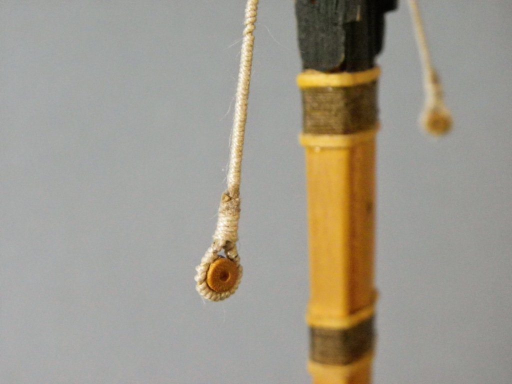
Rigging the Main/Preventer Stays - cont'd I note that in ffm the Main stay passes through the eye on the Port side both for stays, but I recall from my Victory building that Longridge shows the eye for the Mainstay on the Starboard side and that for the Preventer on the Port side. I don't know how significant this is, and I have seen examples of both arrangements, but I intend to have the mouse on the Port side for the Main Stay, and Starboard side for the Preventer Stay. The completed Mouse unpainted. A close-up of the Mouse in place on the stay. At 1:64 scale I am quite pleased with the effect, this is many times the actual size of the Mouse. The other end of the Stay A 15" heart (5.95mm)is attached to the lower end of the stay seizing 1½" (0.19mm) Commencing the throat seizing on the heart. Seizings completed. It helps to have a third hand for this sort of stuff. Lanyard attached. The lanyard is of 3½"circ line (0.44mm ø at scale) This is from Steel; The ffm indicates 2" which seems a little fine or is maybe a misprint. The lanyard will not be tied off until later in the build. I now need to step the Foremast before the Main Preventer Stay is fitted. B.E.


- 366 replies
-
- 3
-
-
- pegasus
- victory models
- (and 2 more)
-
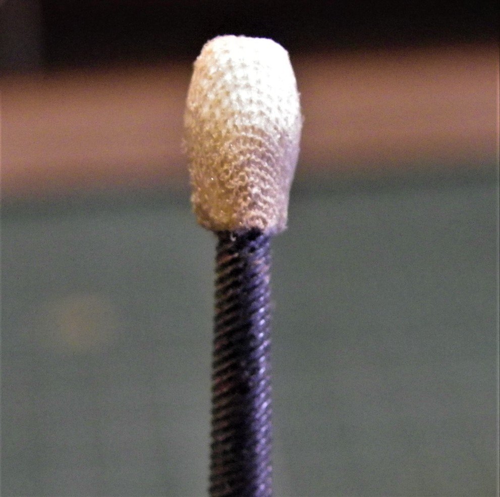
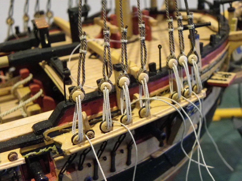
The Main Stay This is the largest stay on the ship at 10" circ equal to 1.26mm ø at 1:64 scale. Syren supply line in 1.37mm and 1.14mm diameters, so do I go high or low? we are only talking 0.1mm difference in the diameter either high or low. I have decided to go high at 1.37mm David Antscherl mentions in ffm that the Main Stay in addition to the serving down beyond the mouse was also served where it passes by the Main mast to prevent premature wear. This sounds reasonable but I've yet to find a contemporary model where this is apparent. I have opted to have the preventer stay running below the Main Stay not least because it lies better that way. Having served the lines I turn my attention to the Mouse. Mouse -Main Stay L = 1/3 circ of stay = 3.96mm ø = 3 x ø of stay =4mm. To make the Mouse for the Main Stay I used styrene tubing; a length of 3.2mm ø tubing inserted inside a length of 4mm ø tubing. This gives me the required external diameter whilst having an internal hole that fits the served stay. The Mouse is formed using files and fine sand paper. Trial fit on the stay. Imparting the weave. The mouse is painted with ca and with the net stretched over and secured sufficient weave effect is achieved at scale. The Main Preventer Stay is of 7" cable (0.88mm ø) which is the same as the shrouds. Mouse - Preventer Stay L =1/3 circ of stay = 2.77mm ø = 3 x ø of stay =2.64mm The Preventer stay and Mouse are prepared as the Main Stay, and the next post will cover installation and attachment of the hearts. B.E.
- 366 replies
-
- 1
-
-
- pegasus
- victory models
- (and 2 more)
-
Completing the Lower Main shrouds. The Main Lower Shrouds have now been installed. Here a close-up of the seizings before staining. The 0.1mm Morope line is ideal for the serving having good definition, is as fine as is available so as not to oversize the finished line, and is completely fuzz free. The downside is it only comes in 4-5 mtr lengths, takes an inordinate amount of line to serve the shrouds, and it is a pain to transfer to a spool without having to unpick a tangled mess, part way thro' the process. Starboard side run.The lanyards which are also Morope (0.4mm) will remain loose until much later in the build. One problem I have found is that having served all the centre sections of the shroud pairs the space in the lubber hole is very crowded and the aft crosstree of the Main top cramps the aftermost pair of shrouds. Still the beauty of rigging the shroud pairs properly is that they are easily removed for adjustment, at least. On the subject of serving the centres of the shrouds; as the pairs move rearwards the line of the served section below the hounds appears shorter because each successive pair sits atop the previous one. On a scale model I think this can look a little untidy if the length differences are too great or uneven so I have sought to reduce the difference somewhat by adding an extra mm length of serving to each successive pair. The next stage will be to make the Main stays and step the Foremast. B.E.

- 366 replies
-
- 2
-
-
- pegasus
- victory models
- (and 2 more)
-
The Main Shrouds These are of 7"* circ line scaling to 0.88mmø * Note: there is a typo error in my copy of ffm Vol 1V (p50) which indicates 10" line for the Fore and Main Shrouds. The kit Mainmast shroud configuration differs a little from the ffm Vol 1V layout. The book version shows a single foremost shroud cut spliced around the masthead, followed by four pairs of shrouds. (nine in total each side) Aft of these are a single Topmast Backstay and a single T'gallant Backstay. The kit version shows four pairs of shrouds, (which obviates the need to splice around the masthead) three standing Topmast backstays, a T'gallant Backstay,and a Flagstaff stay. I have followed the kit arrangement . Steel indicates three topmast backstays. For the first pair of shrouds serving is required for the full length on the foremost shroud, and for a scale eight feet on the second and subsequent shrouds. This serving business. On the model this is the longest section of serving required. I have used 0.1mm Morope and it took around 5mtrs of line to complete the job. Unfortunately the supplied lengths of Morope 0.1mm just fall short of the required length for a continuous run. The line will be dyed after completion. Trial fitting the served shroud. One of the downsides of serving the full length of a shroud is that it tends to stiffen and kink the line. I find that the line needs a little tensioning before fitting to straighten it out. Tensioned and dyed the line is now ready for fitting. To recap I am using Amati 3.5mm deadeyes which actually measure around 3.8 -3.9mm. near enough to the 4mm scale required for a 10" deadeye. (The kit supplied deadeyes are over-scale at 5mm+) With the shroud served it is formed around the false masthead and seized. I have used 0.1mm morope for the seizing. Turning in the deadeye. I like to set the first one up with a distance that suits my eye and then match the others to it. For the first (served) shroud I have slightly deepened the deadeye groove. At this scale I don't bother too much with the throat seizing which will be hidden anyway by the lanyard excess. Having set the deadeye at the required distance I use some thin line to secure the 'throat' with a simple overhand knot, but which allow for minor adjustment in the position. The lanyard is of 3½" circ line which scales to 0.44mm ø line. I am using Morope 0.4mm. It did not prove to be a problem securing the served line with its additional bulk around the deadeye. Final tensioning will be done once the set have been fitted. B.E.


- 366 replies
-
- 3
-
-
- pegasus
- victory models
- (and 2 more)
-
Wow thank you Guys, such generous comments I'm beavering away on the Masting and Rigging recovery but it's going a bit slower than the first part, loads of photo's to find and resize. B.E.
- 366 replies
-
- 5
-
-
- pegasus
- victory models
- (and 2 more)
-
That is very, very, nice work Thomas, puts my fudged efforts around the side tackles to shame. That's an interesting little cheese making device you have there😊 B.E.
-
Nice work Christian, looks like there is room aft of the boomkins for seats of ease, but if you're including the discharge pipes you'll need to check there is free access thro' the headworks. B.E.
-
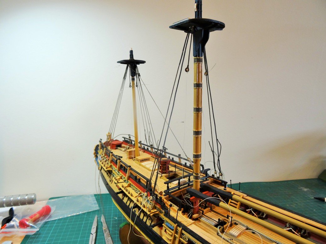
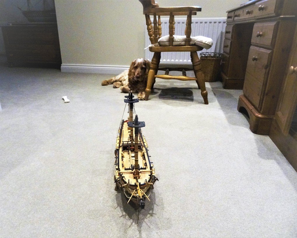
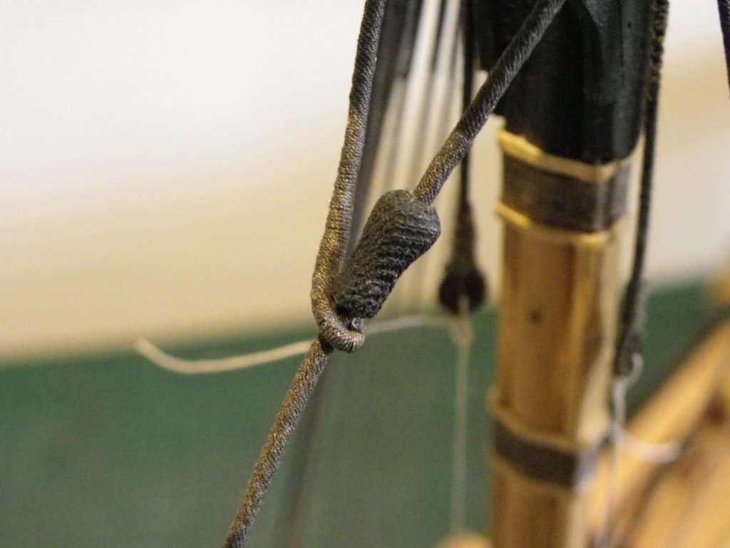
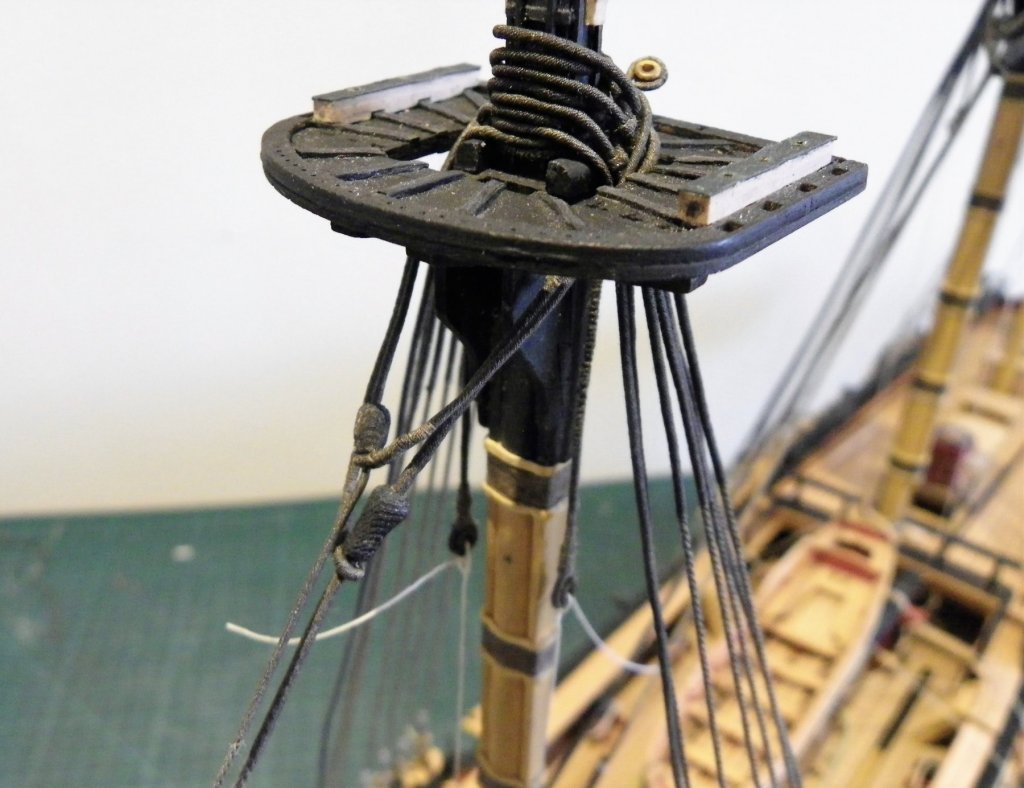
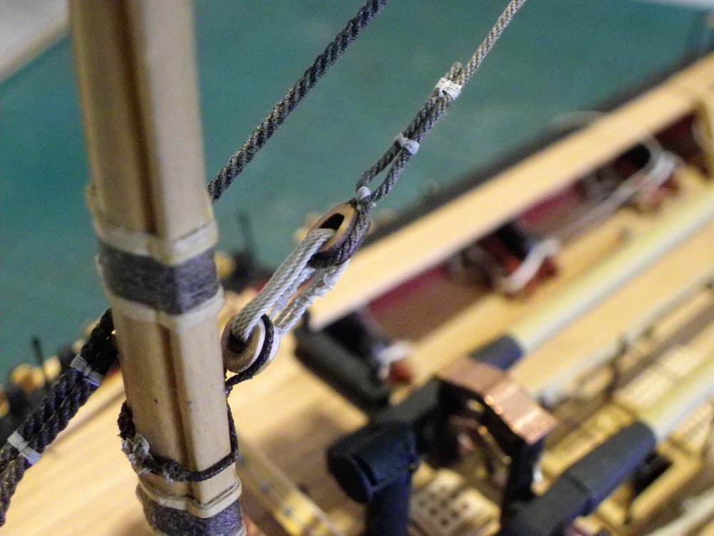
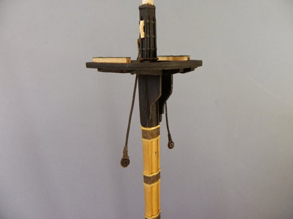
At this point before the Mainmast is glued into place I need to consider any other attachments that may be better done with the mast off the model. I have in mind the Mizen Topmast Stay. The lead for this stay allows for several options, David Antscherl (Vol1V) has opted for a lead thimble stropped below the Mainmast hounds.I have decided to opt for the arrangement whereby an eyebolt is fixed thro' the aft crosstree of the mainmast top and a thimble /lanyard arrangement is used to secure the Mizen Topmast stay. So the Mainmast is fixed; using pva there is time to view from all angles to ensure that the mast is set square to the centre line. I like to set the model on the floor so I can view it directly from above. What do you think Wills does it pass muster? The Mizen Stay is now attached by its lanyard. 2½" (0.3mm)lanyard. So for the present this is as far as the Mizen Standing Rigging is taken. I will next deal with the Main Shrouds. B.E.

- 366 replies
-
- 1
-
-
- pegasus
- victory models
- (and 2 more)
-
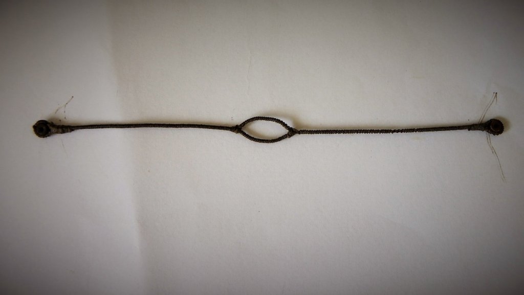
Mizen Stay cont'd Before I determine the length of the Mizen Stay I will attach the Mizen Stay collar to the Mainmast. This involves seizing a 5" heart (2mm at scale) at a point around seven feet (33.3mm) above the Quarterdeck. The requirement is for served 4" (0.5mm) line lashed with ¾" line on the forward face of the Mainmast. I have gone with 0.4mm Morope served with 0.1mm line I find these tricky things to get right as two eyes have to be formed in the legs of the collar, but sufficiently apart once around the mast to allow for the seizing. A mock collar is required to determine the length. The finished strop is 43mm in length. Trial fit around the Mainmast. Seizing in the lower heart. The next stage will be to set the Mainmast which will then allow fitting the lanyard to the Mizen Stay. B.E.
-
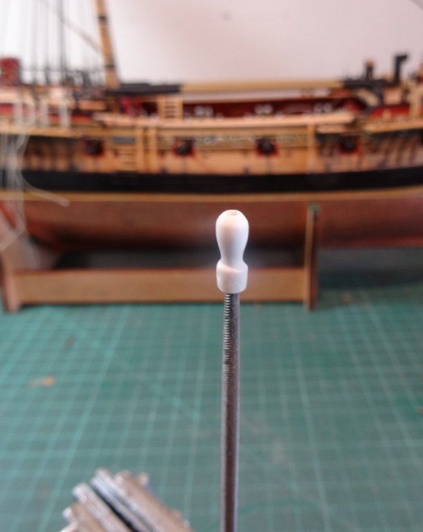
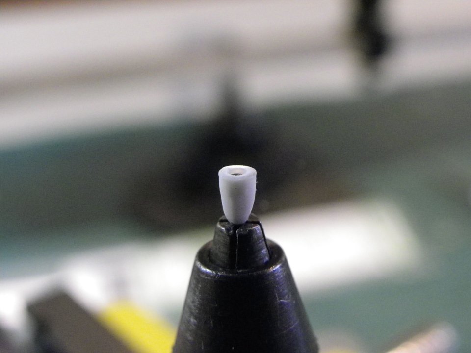
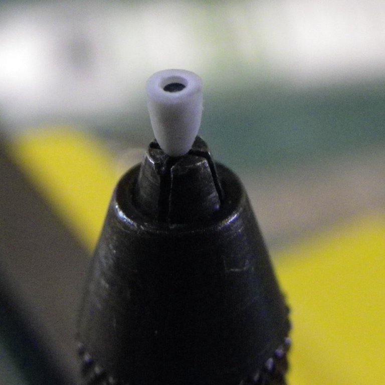
The Mizen Stay. The Mizen Stay is of 5½" circ. equal to 0.69mm ø at scale. I will use Syren 0.63mm ø which the closest size I have. Making a stay involves a couple of tricky little procedures. Firstly the stay has an eye spliced in one end and is then served* down to a point a little beyond where the mouse will be fitted. *A note about ffm Vol iv (p50) The Mizen stay is covered first, but there is no mention in the text that the stay should be served to a point below where the mouse is fitted. Not until p52 is reference made to serving the line in relation to the Main Stay, with a referral back to the Mizen. Once the serving is started and the eye formed the line can be put on the serving machine to complete the eye. It is then necessary to work out how far down the stay the serving should go. The limit of the serving is marked. The serving is completed. (It will be dyed later) 0.1mm ø Morope line is used for serving. Trial fit on the masthead. Making the Mouse. The full size Mouse is some three times the diameter of the stay which scales to around 2mm max diameter. I have formed mine from Evergreen styrene tubing of 2.4mm diameter. This fits nicely over the served stay. The mouse is a tad under 5mm in length. Forming the Mouse Using a scalpel and fine paper the cone is formed. Trial fitting of the Mouse. The real mouse is woven on the stay which would give a patterned effect. To replicate this I apply c.a. to the mouse and then stretch some old tights material donated by Mrs W over the mouse and trim. The mouse is then painted and an impression of weave is imparted. The next part will cover the completion of the stay by the addition of the hearts and lanyards. B.E.


- 366 replies
-
- 1
-
-
- pegasus
- victory models
- (and 2 more)
-
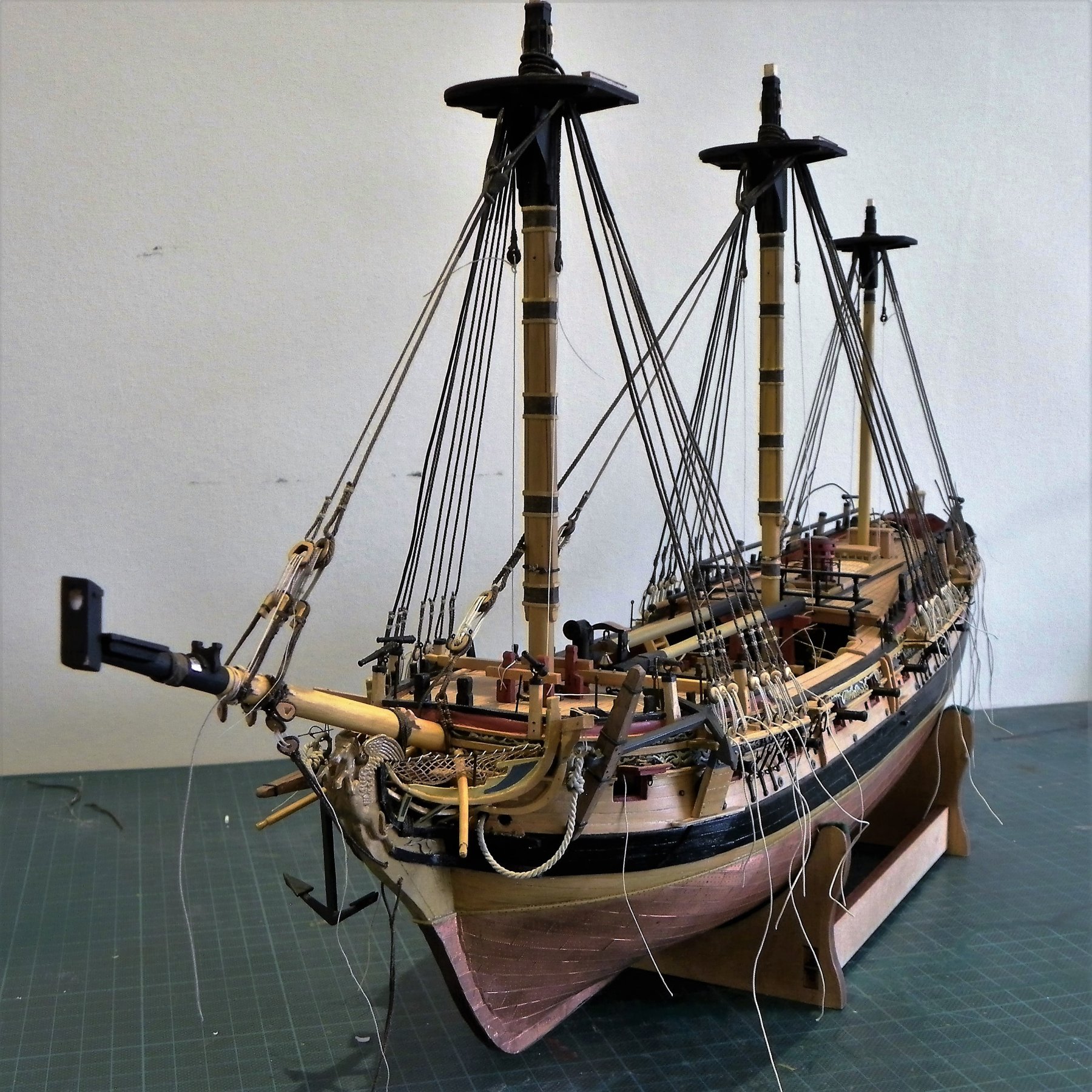
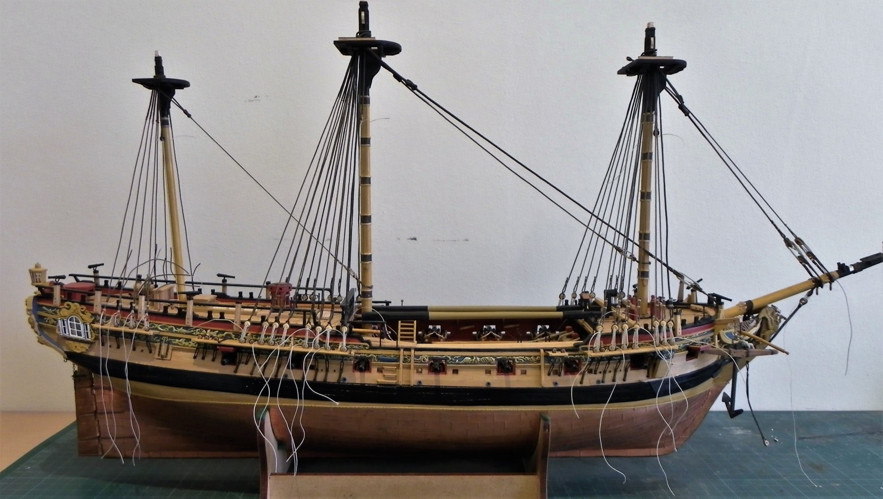
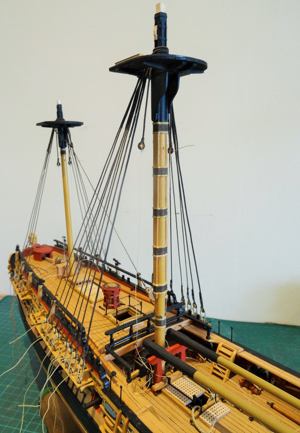
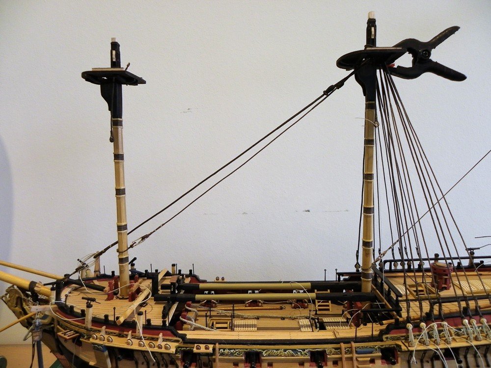
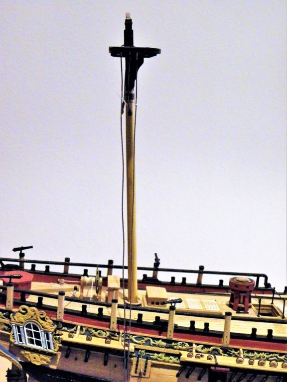
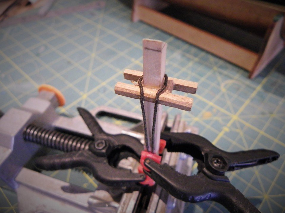
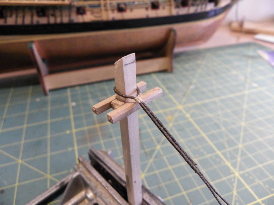
Stepping the Masts and the lower rigging begins Resuming work on Pegasus, I have now reached the stage to mast and start the lower rigging. I start the process by fixing the Mizen Mast. I use the merest spot of pva to secure the mast, sufficient to keep it in place, but would allow removal (hopefully)by a sharp twist should the need arise. The rigging will start with the Mizen and I will work my way forward so as not to impede access to fixing the Mizen and Main Stays. The Mizen shrouds are of 4½" circ line which equates to 0.57mm ø; I will be using Syren 0.63mm ø line. I am using the original tan Syren line dyed with Dark Jacobean oak woodstain. This produces a tone less than black which I think suits the scale and my eye better. The shrouds are served over the centre quarter section, and for this I am using 0.1mm ø line. Syren don't make a 0.1mm ø line so I tried some Amati stuff but this has proven unsatisfactory because of excessive fuzziness, so I have reverted to Morope 0.1 and 0.25mm stuff for serving and seizing which is well defined and is fuzz free. The first job is to mark where the serving will extend to; this is done on the model. I prefer to perform the seizing off the model and to this end a 'mock' mast head held in a vice is used. This is easier on the arms than seizing directly on the model and the completed shroud pairs are simply then slipped over the masthead proper. The deadeyes for the Mizen shrouds are 7"ø which equates to 2.77mm at scale. I am using Amati 2.5mm ø which work out at around 2.7mm, about right for the purpose. My approach to shroud rigging is to do it entirely on the model setting up the starboard pair first and adjusting the line of the upper deadeyes as I move along. This can prove a frustrating exercise, particularly when somewhat 'ring rusty' after a five month lay off. The lanyards are of 2½"circ line which scales to 0.3mm ø line, which Syren do produce. Note the nice definition of Chuck's 0.63mm and 0.30mm line. The lanyards will not be tied off and trimmed until much later in the build. B.E.
- 366 replies
-
- 2
-
-
- pegasus
- victory models
- (and 2 more)
-
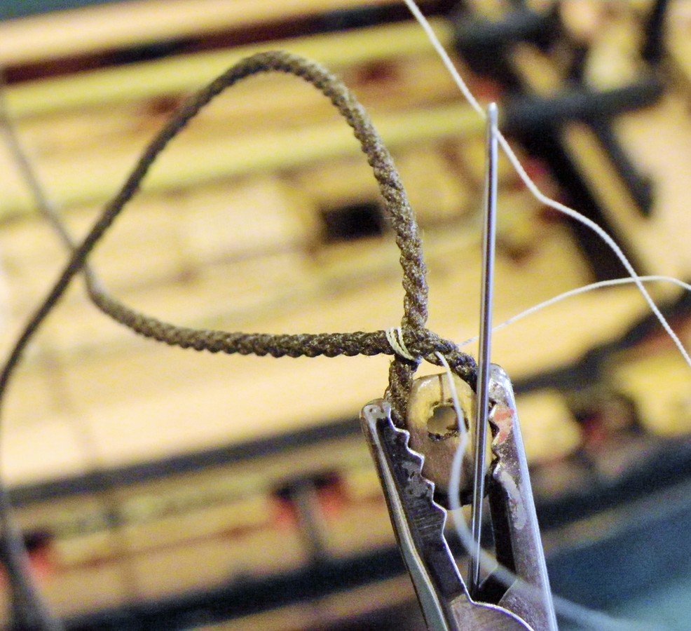
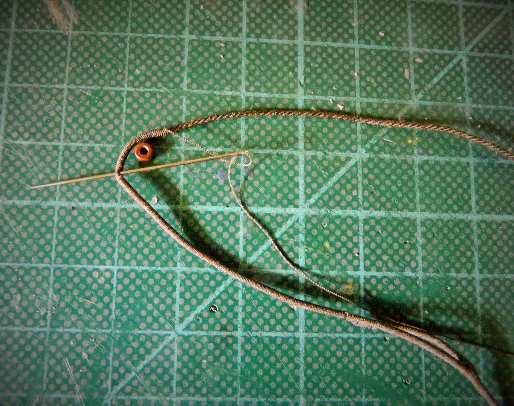
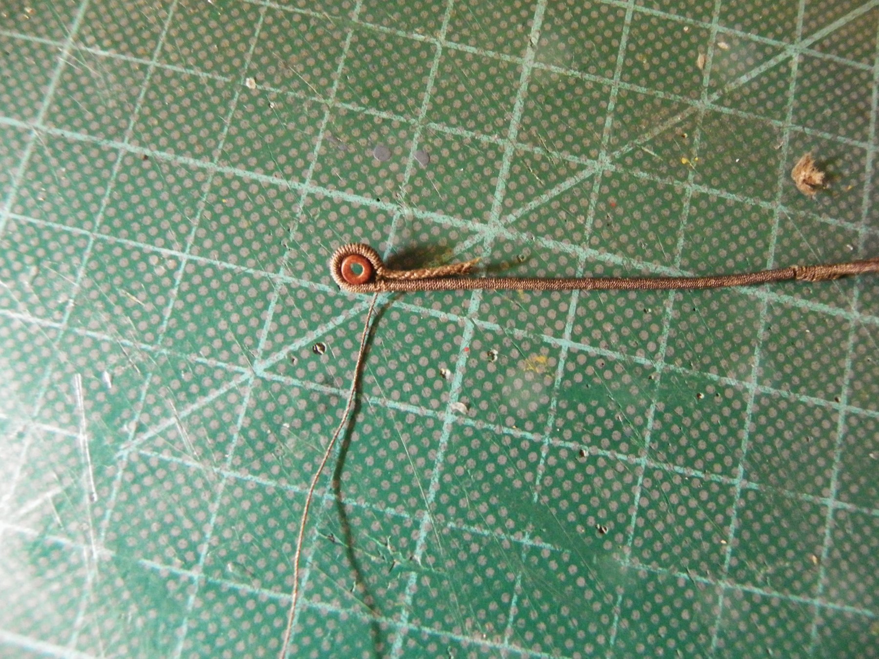
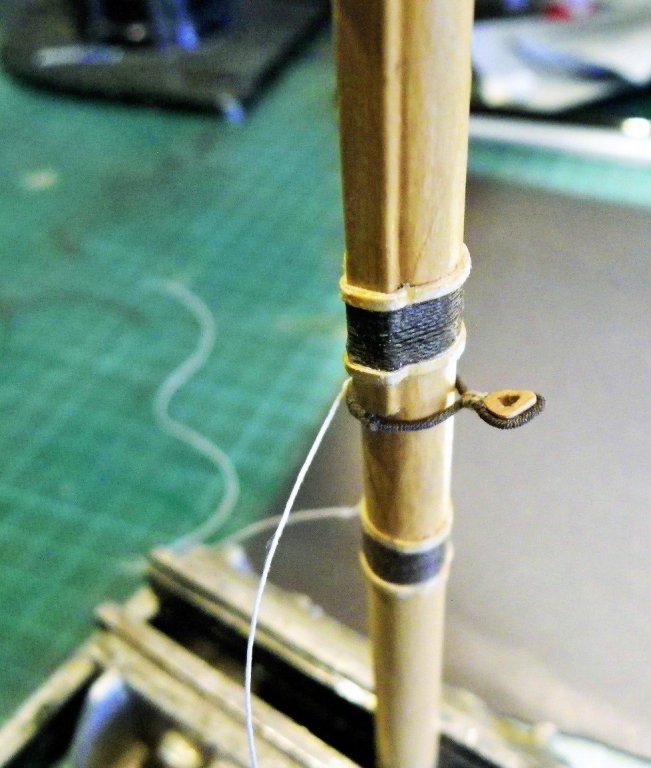
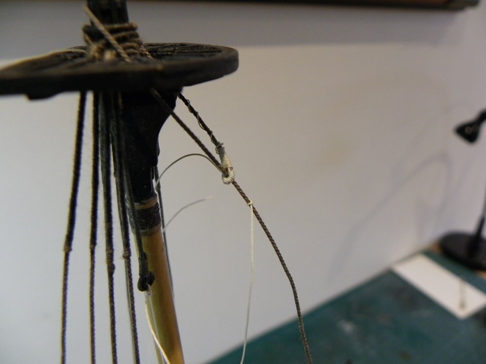
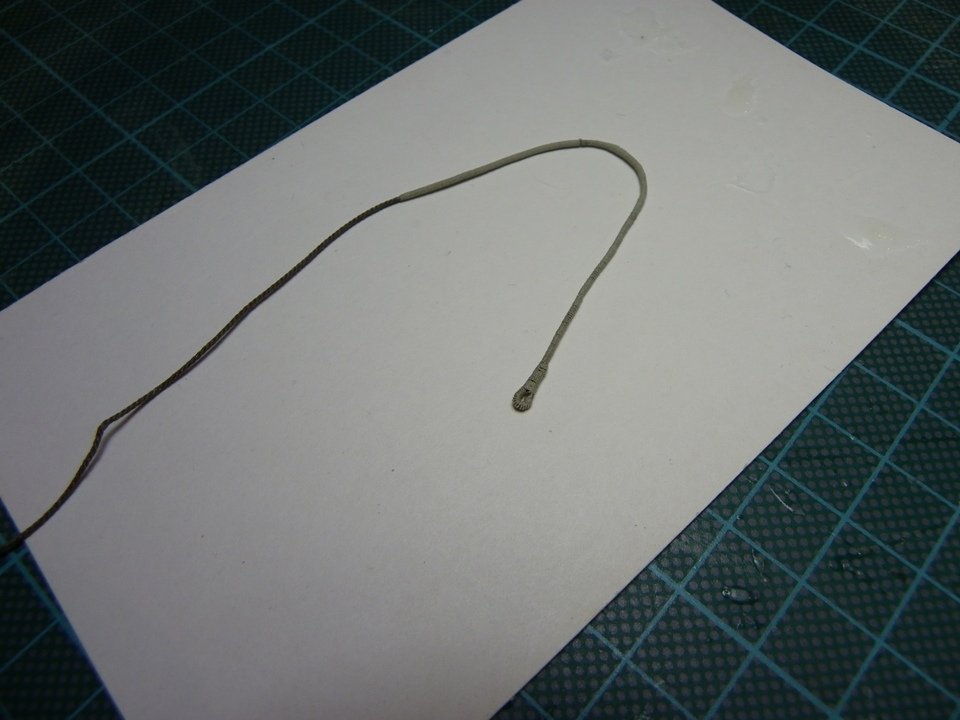
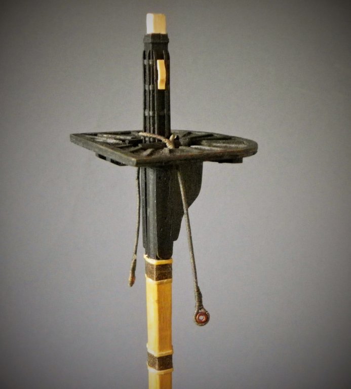
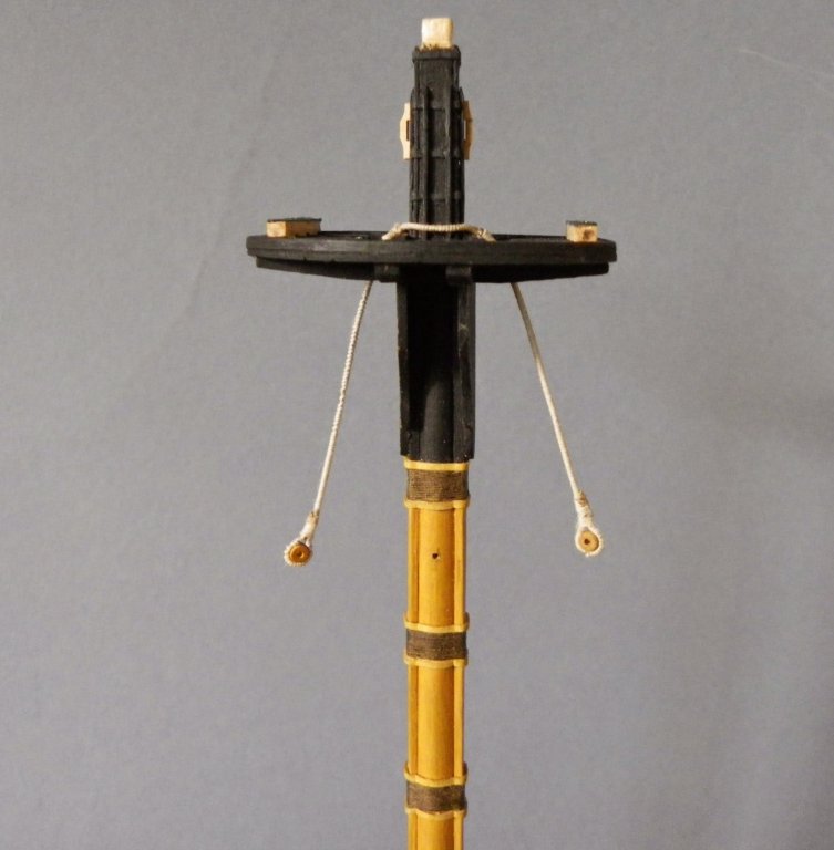
Fretting over Pendants Now that the Syren line has arrived I can have a go with the proper stuff. For the Main and Fore pendants I am using 0.88mm Syren line and 0.15mm Morope for serving. The materials 0.88mm syren line 0.15mm Morope for serving. The sizes 17mm length of splice section. 59mm from splice join to end (allowing for turn in of Thimble) 130mm o/a length of Pendant The procedure The Pendant line is thinly coated with pva to help secure the serving line and keep it tight. The combination of Syren line and Morope serving works well, no fuzz. The method then follows that shown in the previous post. At the thimble end the served line is carried around the thimble until the served ends meet and the tail length of excess serving line is taken thro' the served line using a needle to secure. The excess unserved pendant line is sliced at an angle to reduce bulk for the seizing of the thimble. The wooden Amati 2.5mm ( but nearer 3mm) thimbles are modified by enlarging the hole to reduce the profile, and by deepening the groove around the edge. Happy with the upper splice but still have niggles about the thimble look and seizing. The Mizen Burton Pendants One pair on the Mizen, using Syren 0.45mm Ø line. served with Morope 0.15mm Ø line. 15mm of splice section, 40mm length to turn. For the thimbles I tried slices of 2.3mm Ø styrene tubing. So the full set. B.E.


- 366 replies
-
- 1
-
-
- pegasus
- victory models
- (and 2 more)
-
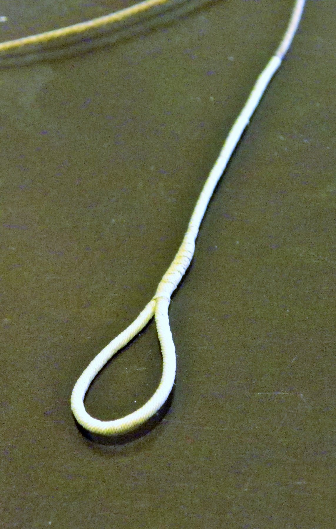
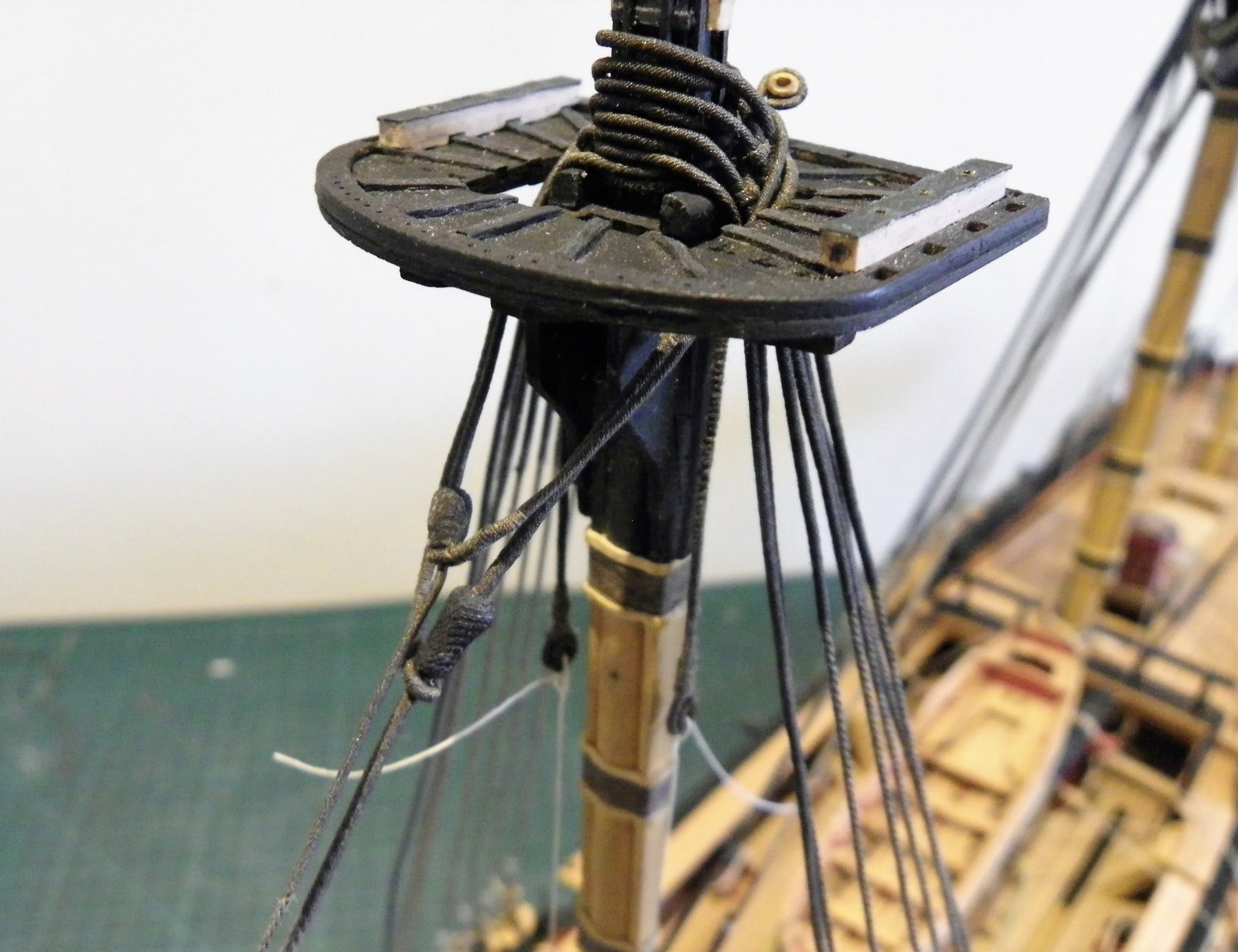
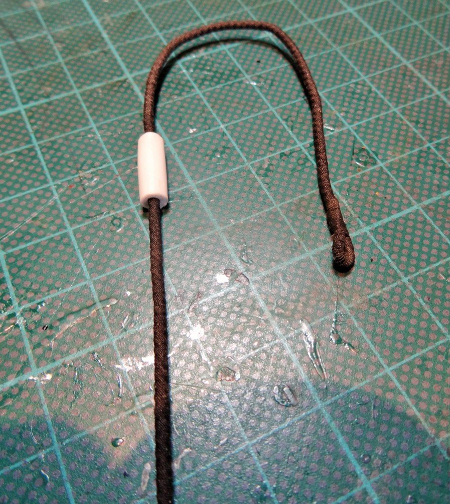
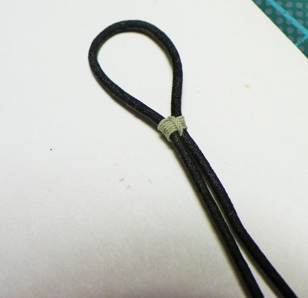
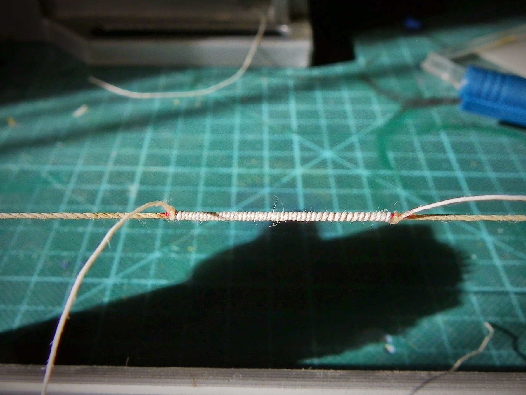
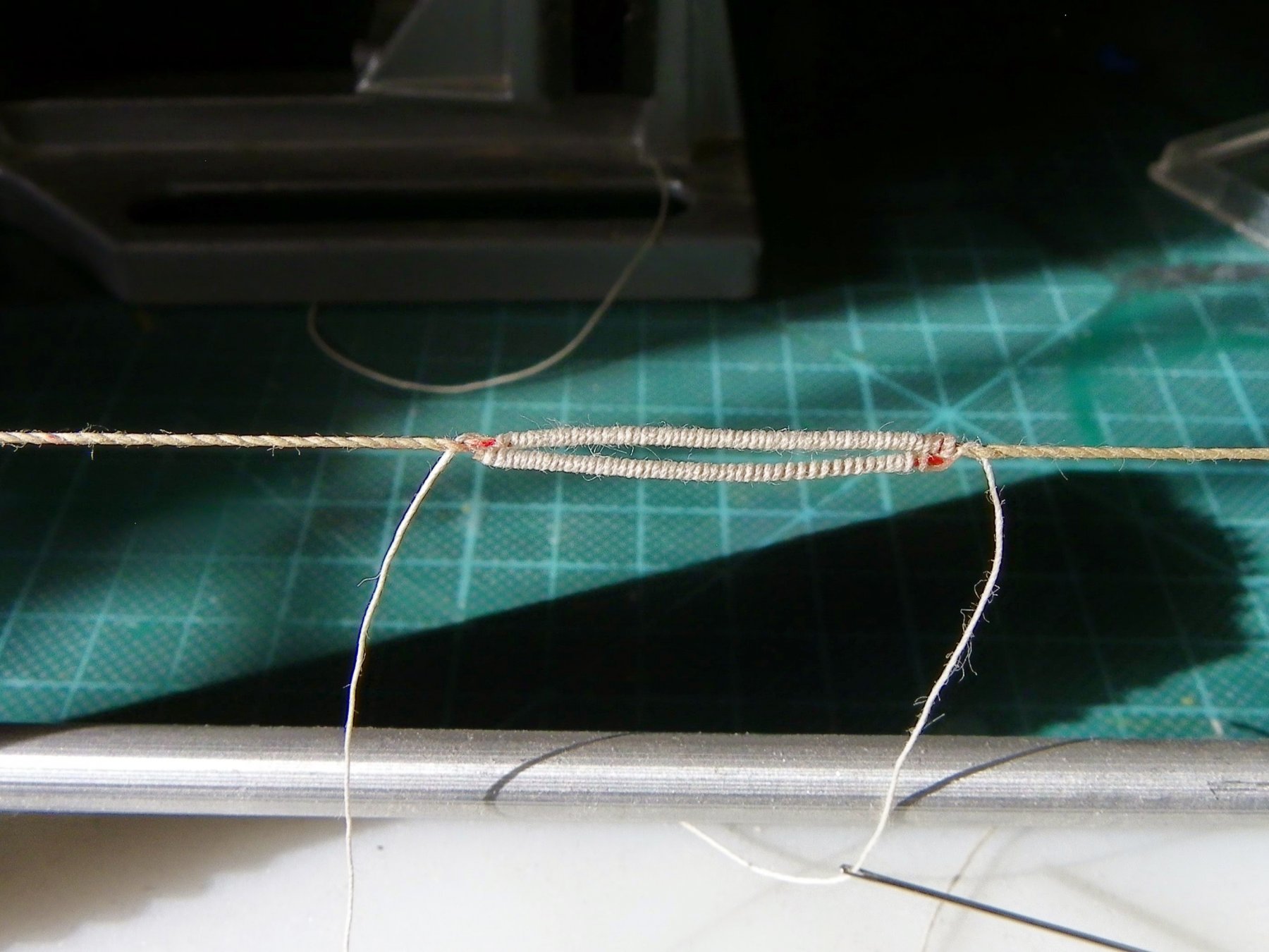
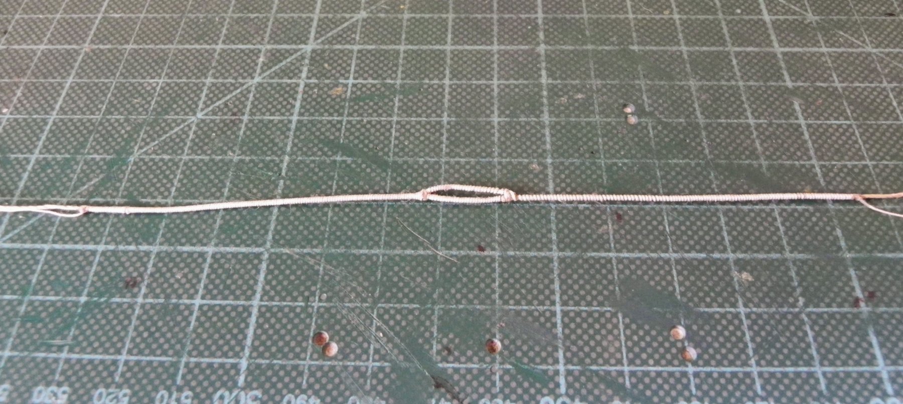
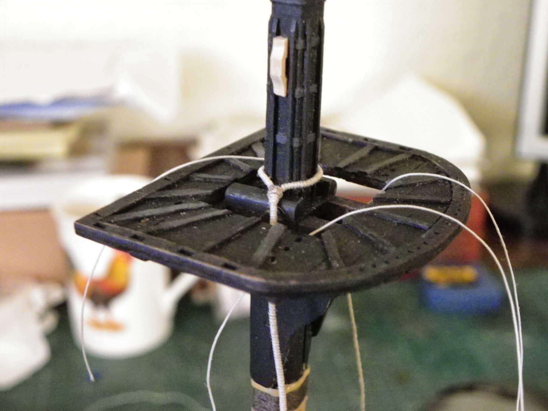
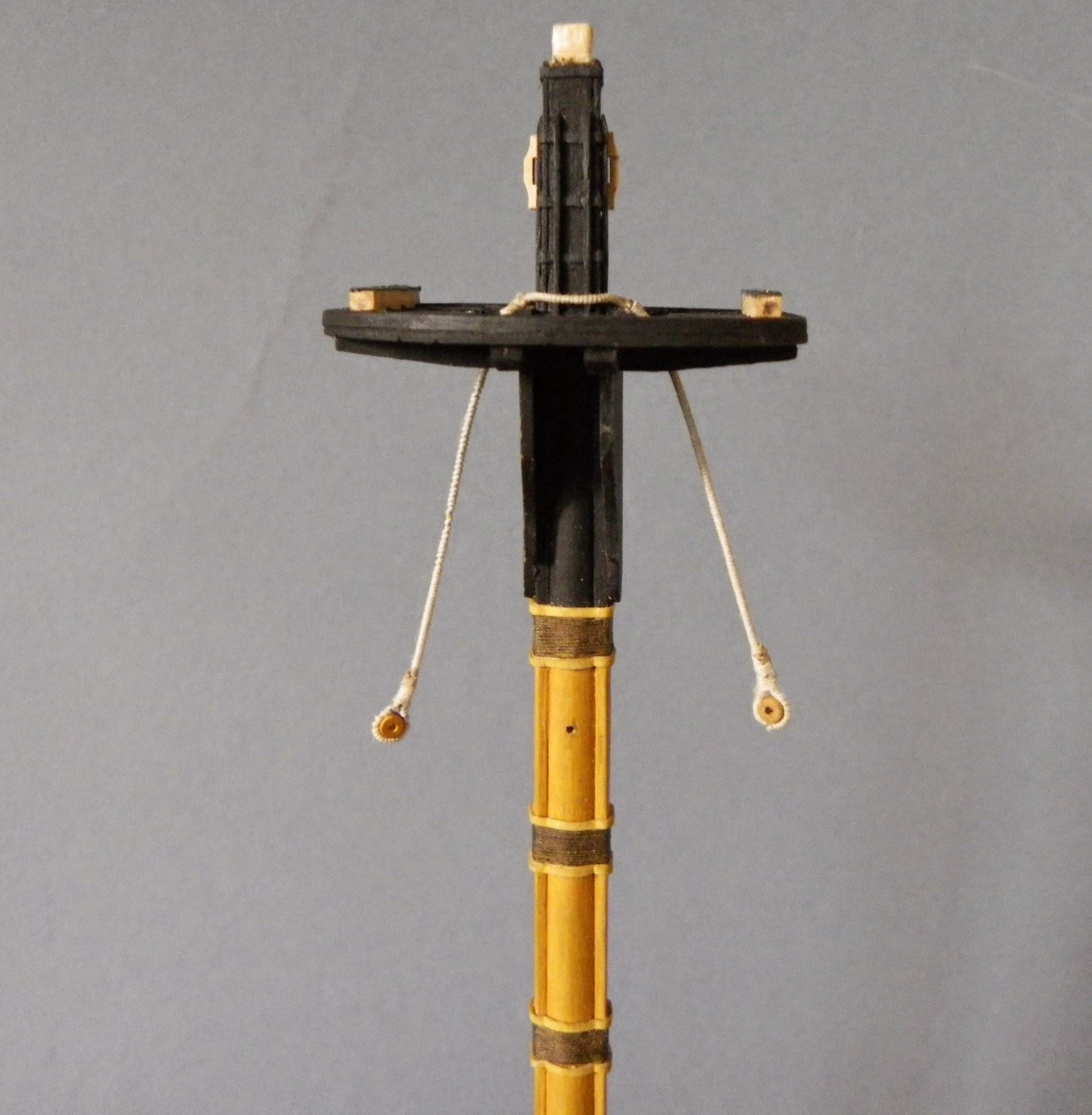
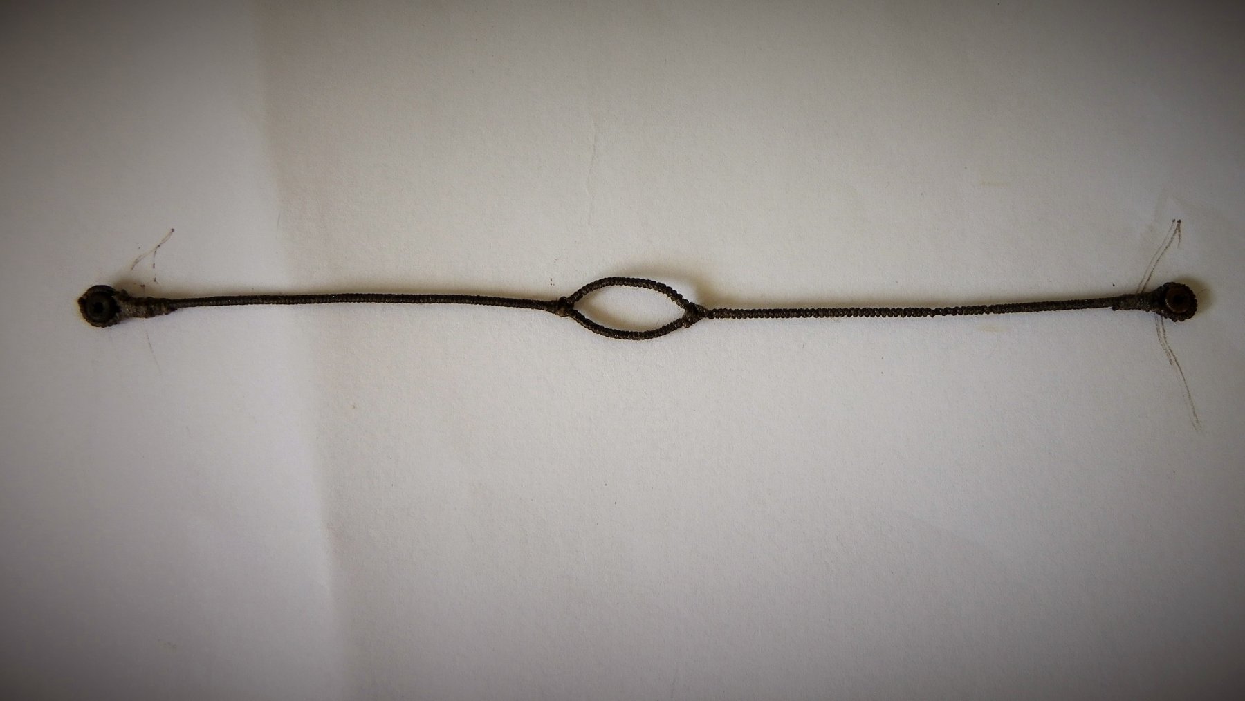
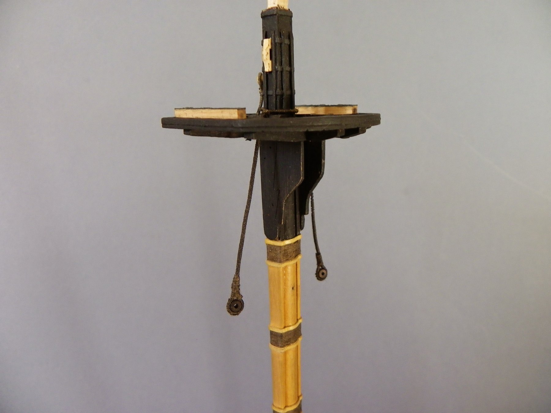
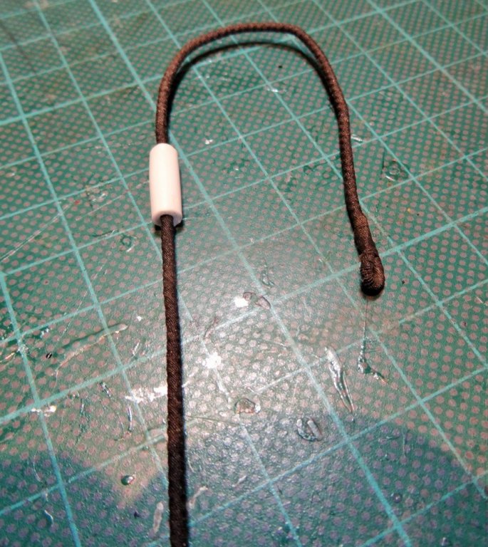
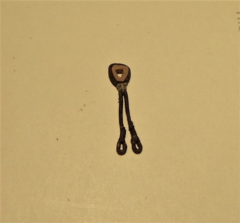
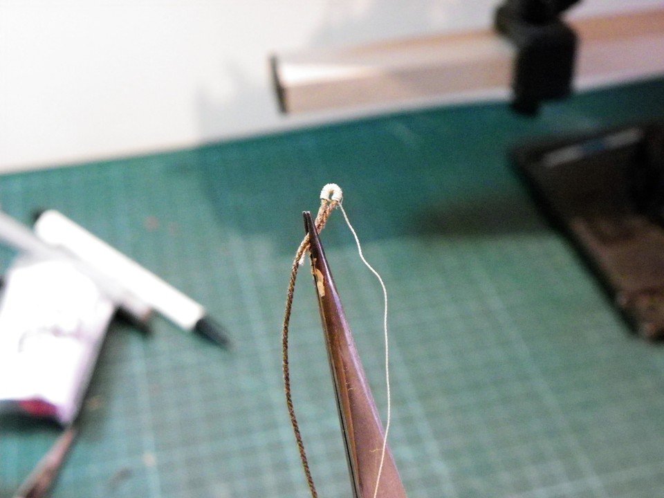
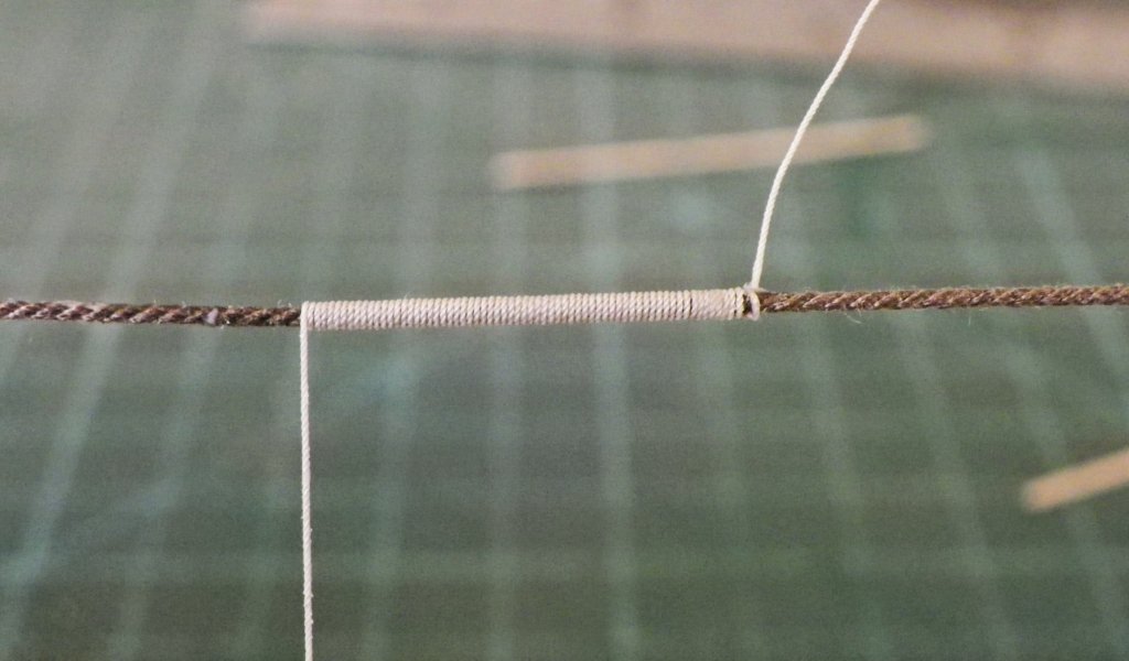
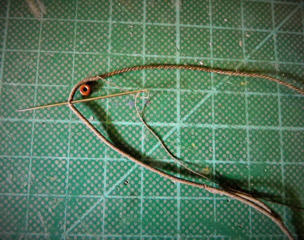
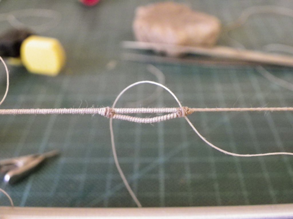
This post begins the long road to rigging proper Pendants of Tackles (Burton Pendants) These are the first items of rigging over the Mast heads.For the Fore and main masts the Pendants are of 7" circ served line which equates to 0.9mm Ø and for the Mizen 3½" served line scaling to 0.44mm Ø One pair of Pendants is used on each mast and a thimble is turned in the end into which the tackle blocks are hooked when required.Note: these important items of rigging seem to have been omitted from the kit plans, but if they are to be fitted they need to be attended to before the shrouds are fitted.There is a little bit involved with making the pendants, they should have a cut splice where they fit over the masthead, should be served all over, and have a thimble seized into the lower ends. How to proceed? Whilst I wait for my line supplies to arrive I have given some thought to creating the Pendants, and this is by way of a practice piece. I first I measured the length of line required to form the splice over the masthead. This was served. An additional shorter length of line was also served to match, with unserved tails each end. This second line was positioned and was secured with fine line. A needle was used to pass the 'tail' thro' the main line to secure it. The splice is thus formed The combined line was then served either side for the required length. The splice was tested for fit over the Masthead. Thimbles were seized into the lower ends of the served line. Steel does not give the size of the thimbles in his tables but the ffm book takes a punt at 4-5" Ø. This scales to 1.6 - 2.0mm. I've used Amati 2.5mm thimbles and it's difficult to see how anything any smaller would accommodate the served line. One of my concerns is that the seizing of the thimble doesn't look too bulky, some work required on this I think. Once completed the whole thing was dunked in the dye and this is the result. For this exercise I used Amati 0.75mm Ø line served with Jotika 0.1mm Ø line. which on paper is a little under scale, but which doesn't look too bad to my eye. Now I've established my approach I will remake a sample pendant using Chuck's 0.88mm Ø line when it arrives. B.E


- 366 replies
-
- 2
-
-
- pegasus
- victory models
- (and 2 more)
-
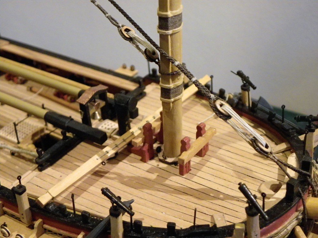
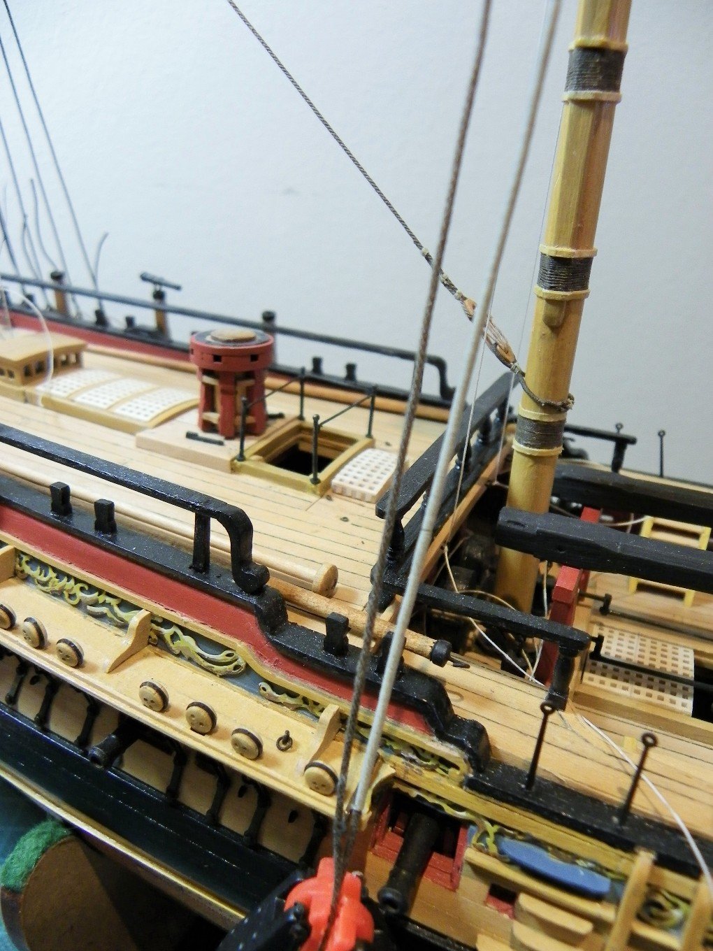
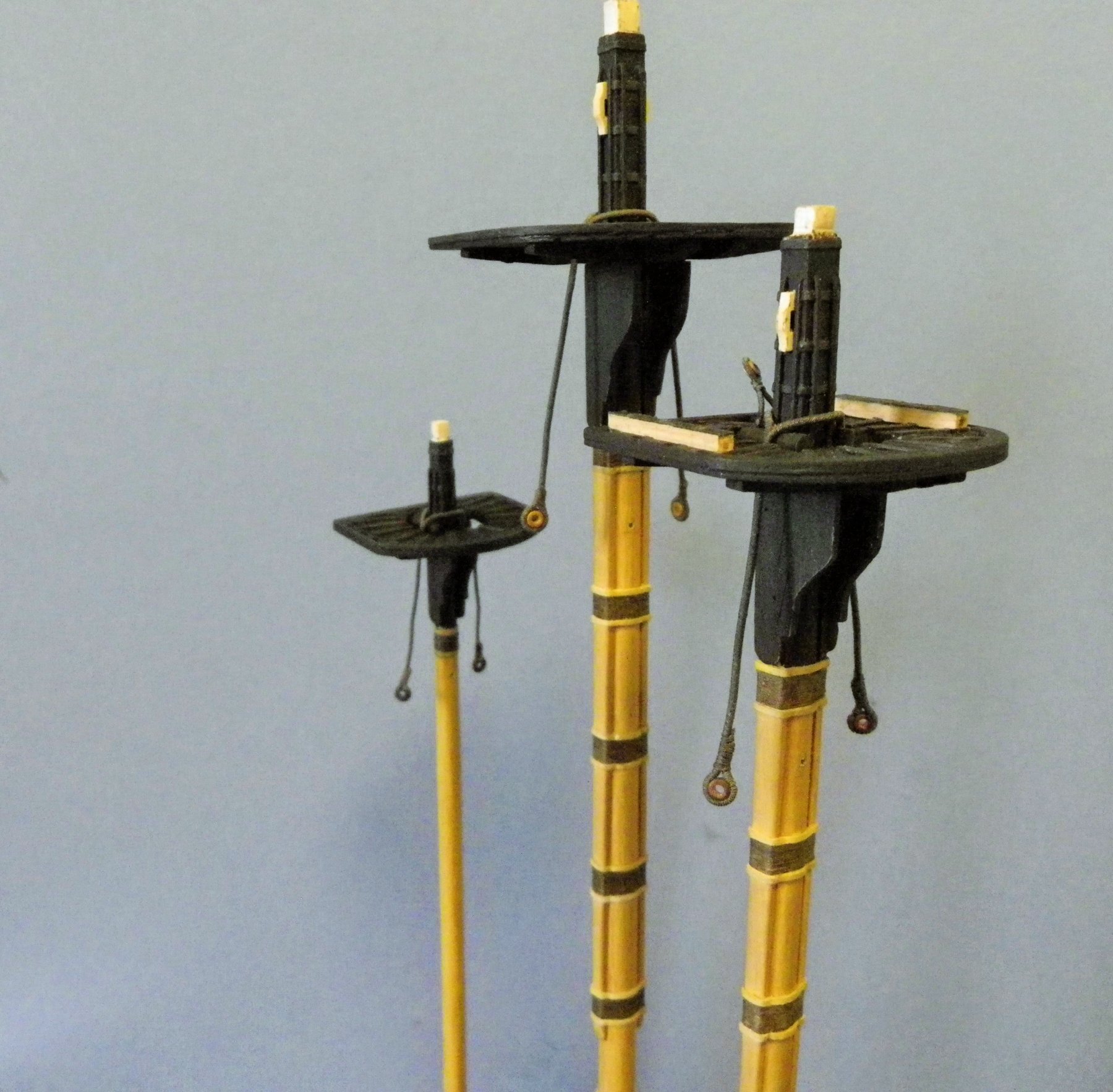
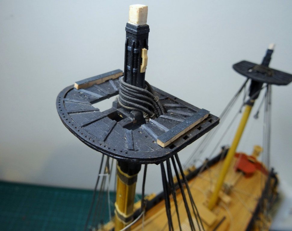
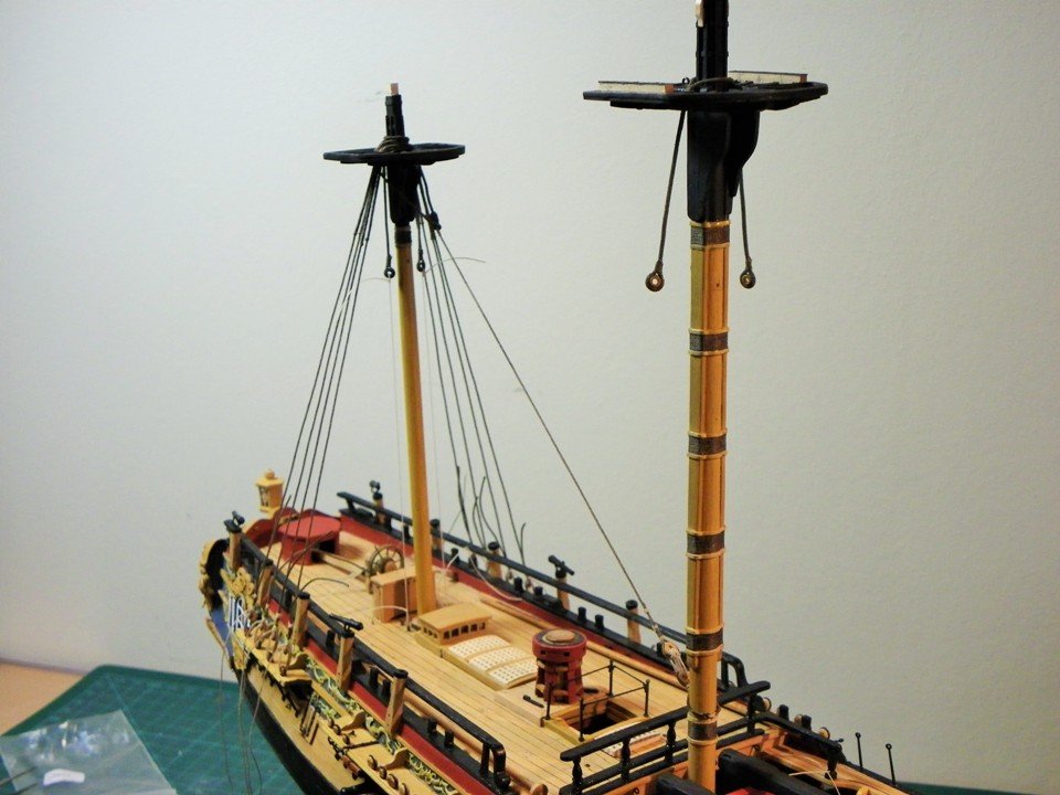
A small progress and a little modification that is fairly easy to make. These are the Swivel gun mounts for the Tops. They consist of two lengths of 3x3mm boxwood strip, with three mortices for the gun mounts positioned to fall between the deadeye slots. These should be square in section but given the scale I have gone with round. The holes are lined with brass tube into which the swivel mounts fit by means of a sprig on the end. The top of the mount should be covered by an iron plate, I have replicated this using thin black card. So here's the Fore Top with mounts in place. For the present I have left them natural boxwood so they show up better. B.E. Thu Oct 23, 2014 11:02 am
- 366 replies
-
- 2
-
-
- pegasus
- victory models
- (and 2 more)
-
Rigging the Foreyard This is a summary of the Foreyard rigging, the procedure is the same as that for the Main Yard more fully covered earlier in the log. I record this simply as an aide memoire to the line/block sizes I used. The first item I tackle is the Jeer block on the centre of the yard. 7mm single JB Pearwood block stropped with 0.25mm Amati line served with 0.1mm line. For the double strop a served length of 85mm is required plus additional line to effect the splice to join the two ends together. The Quarter Blocks - are next up, two 5mm JB Pearwood blocks stropped and served with 0.25mm line,38mm of served line was used. I didn't go to the trouble of making two eye splices in the strops with a seizing, too much effort with too little visual benefit. Moving outwards the 9” clue blocks are next; these scale to 3.57mm. I have gone here with Chuck’s 5/32” single boxwood. These are a little overscale but I want to maintain a visual difference between these and the slightly smaller bunt and leechline blocks. These should also have served strops with eyes but given the small scale I have forgone the pleasure of attempting this and simply used 0.25mm line for the strops. Moving out along the yard the Bunt (8”) and Leechline (7”) blocks are required next. For these I have gone with 3mm pearwood blocks. Note the kit plan include only the buntline blocks. The smallest blocks along the yard are the 6”Tricing line blocks which scale to 2.38mm. (I used 2mm blocks) Onto the Footropes and Stirrups The Stirrups are of 3½” (0.5mm Ø) line and the Horses of 2½” (0.3mm Ø) Line. (I used 0.25mm line) Bob helps me determine the stirrup length below the yard, and a length of brass tubing threaded thro' the stirrup eyes and weighted holds the line taut. The Footropes are attached with a false eye splice to the yard arm, threaded thro' the stirrup eyes and attached outside the sling cleats with another false splice. The line is then weighted and coated with diluted wallpaper paste which imparts a stiffness to the stirrup and hopefully avoids any tendency for the footropes to curl under the yard. The footropes are also coated in diluted wallpaper paste to impart a stiffness to them. Bob does the final 'fit' test and it's good to go. As with the Main yard two non regular types of block are required. The Thin Long tackle blocks for the yard pendants - these were scratch made from boxwood as covered earlier in the log and stropped and rigged as per the Main yard. The Topsail sheet blocks are shoulder blocks and 5mm pearwood blocks were modified for the purpose again as per the earlier examples for the Main Yard. 4mm pearwood blocks were used for the 9" attached lift blocks. I used 0.25mm line for the strop and 0.1mm line for the serving. Dyed Amati rigging line was used for the purpose. The length of the served line was 45mm, although additional line length was allowed for the eventual securing to the yardarm. The Cro'jack yard Fortunately this yard is free from the multiple blocking and footrope requirements of the other two lower yards.. Just as well as I'm struggling to maintain interest for this block stropping malarky. Necessary blocks Sling tye block 10" = 3.97mm (I used 4mm Pearwood blocks) Strop - 3" line = 0.38mm Ø (I used 0.4mm Morope) Seizing - ¾" line - 0.1mm Ø The eyes and legs were made for this strop, not that much detail can be seen at the scale involved. Quarter Block 10" = 3.97mm ( for these I used 5/32nd Syren boxwood blocks) Strop -3" line = 0.38mm Ø (I used 0.4mm Morope) I forwent the pleasure of forming stops with eyes and legs for these attachments. Brace Pendant 2" = 0.25mm Ø 12' long = 57mm Brace Block - 6" = 2.4mm. The pendant is seized to the yard some 4' (19mm)in from the yard arm Topsail Sheet Block-10"=3.97mm (I used 4mm Pearwood blocks) Lift Block - 6" = 2.4mm ( for these I used 3/32nd Syren boxwood blocks) *Strop 1½" = 0.189mm Ø *Note: The ffm (page107) indicates that the sheet and lift block combinations are stropped with 1½" line. I believe this to be a typo error, and I have used 0.4mm Ø line for this purpose. The completed fittings on the Cro'jack yard. B.E.
- 366 replies
-
- 2
-
-
- pegasus
- victory models
- (and 2 more)
-
The shoulder block/ lift block combo are completed. I reduced the seizings between and beneath the blocks to make them more compact and closer to the yard. I used 0.25mm line for the strop and 0.1mm line for the serving. Dyed Amati rigging line was used for the purpose. The length of the served line was 45mm, although additional line length was allowed for the eventual securing to the yardarm. Brace block 8" (3mm) 3½" (0.45mm Ø) served line 14-18ft (67 - 86mm) long pendants. I have decided to leave the Brace block pendants and fit them insitu when I can get a better visual impression of the lengths relative to the model set up. In these two shots my latest addition to the motley crew makes his first appearance. This Lemuel 'nimble' Jones, quite what he's doing on the Main top I don't know he's the newly appointed Helmsman, bit of an adrenalin junkie I've heard. So that's it a more or less completed Main Yard; I now need to repeat the exercise with the Fore Yard and whatever applies to the Cro'jack yard. B.E.
- 366 replies
-
- 1
-
-
- pegasus
- victory models
- (and 2 more)
-
Picking up on the yards. I last looked at the yards back in December 2013 and as I've now run out of options to distract me having completed the boats, I need to gee myself up to start again. To recap I had reached the point of fitting out the Main Yard and one more Yard tackle pendants is required and a couple of other fittings before I move onto the other yards. My intention is to complete all the yard fittings before I step the masts so that Pegasus can remain snug in her temporary case. I'm not particularly looking forward to this part of the build as I find fitting out the yards repetitive, fiddly, and quite dull work. To recap The pendant is of 4½” served line (0.5mm dia) and the falls of 2½” line scaling to 0.3mm dia. The length of the pendant including the stropping and eye splicing is 62mm. I found served true scale line too heavy for the block so I reduced it to 0.25mm line served with 0.1mm line which better suits my eye. To make the pendant the line was served the required length with a good amount of unserved line either end. The ‘false’ splice method was used to strop the block, and similarly to make the eye to fit around the yardarm. Here the excess serving line is being used to create a 'false' splice to form the strop of the LT block. The needle pulls the serving line thro' the strop line and pulls the two together. The serving line end is then taken back thro' the strop, a few turns around the strop, secured with a spot of glue, and trimmed. A similar procedure is used to form the pendant eye that fits over the yard arm. A matched pair. Outside of the Yard tackle pendants comes the Topsail sheet block with its associated lift block, and finally the brace block pendants. These are the stats Topsail sheet block 12" (5mm) with 4½" served line. 0.5mm Ø Lift block 9" (3.5mm) Brace block 8" (3mm) 3½" (0.45mm Ø) served line 14-18ft (67 - 86mm) long pendants. The Topsail sheet blocks are interesting as they are shoulder blocks. Won't find any of these commercially available as far as I know, so the first job is to cobble one together. I am using 5mm Pearwood blocks. To modify the 5mm block to give it a shoulder one end is filed flat onto which a small extension piece is glued. and then filed to shape This is the result. Stropping the combined blocks. Fitting for the eye. So Gromit d'ye think there's too much seizing between the blocks, hmmn I'm not too sure either. I'll make up the other one with slightly less and review the arrangement. B.E.
- 366 replies
-
- 2
-
-
- pegasus
- victory models
- (and 2 more)
-
Stays, Collars, and hearts. This post is all about collars and stays and getting the right lengths and positions. I want to avoid as far as possible finding some way down the road that the Mainstay falls in an inconvenient position as it passes the Foremast, that the collar positions the heart correctly, and that the preventer collar heart sits the right distance on the Foremast below the Main stay. All this requires a mock up, firstly to gauge the length of line necessary to make the Mainstay collar, and also to mark the position on the Foremast for the Preventer collar. The mainstay collar heart is got into the right position and the collar is marked where the eye splice needs to be formed. With the Mainstay position checked the heart for the preventer stay can be positioned on the Foremast. About 2 scale feet below the Mainstay. Satisfied that the arrangement will work, with no fouling of the wooldings the mock- up can be dismantled and work started on the proper collars. The Main Stay Collar Tricky little beggar this involving feeding a line thro’ the hole in the stem, forming a bight into which a closed heart is seized, an eye splice, thro’ which the loose end is passed and then taken back on itself and secured with three seizings. The latter requiring to be done on the model. The main consideration is working out the correct length of line; Steel indicates six fathoms (171mm) of 8” served cable (1mm) with a 15” closed heart (6mm) My test collar worked out at 147mm in length to bring the heart to the correct position. Starting the seizing around the heart. For the collar I am using 1mm Amati line served with 0.1mm line. The fiddliest part of this exercise which has to be done on the model are the three seizings that secure the collar where it returns on itself having passed thro’ the eye splice. The fact I’ve already fitted the horse and netting along the head rails doesn’t help. Main Preventer Stay collar 41/2” cable (0.6mm) I will be using 0.5mm line with a 0.1mm serving.) 11” heart 4.4mm. This collar fits on the Foremast, again with two eye splices and a lashing on the forward side of the mast. I was interested to see if I could reproduce a Rose Lashing on this collar.. but the danger at this scale is that it simply looks an untidy mess. So this is the result; I call it the Star trek lashing – it’s a rose Jim but not as we know it! I think it shows something of the design but I had to draw a line at producing the finishing flourish of a pair of Wall knots on 01mm dia line. This is what the Boys Manual of Seamanship has to say about it: A Rose Lashing A rose-lashing can be passed either with one end or two. To pass a rose-lashing on one end, splice the other end into the eye of the strop or collar you are going to lash, then pass either from right to left, or left to right, passing it over the eye on one side and under on the other, until sufficient number of turns are passed to bear the strain equal to the collar or strop being lashed, which is generally about seven turns ; then the end is passed between the crossing turns twice, and dipped up through as near the centre of the seizing as possible, and is finished off by crowning and walling the end close to the crossing turns. To Pass a Rose Lashing on both Ends of a Lashing. The lashing is middled in the centre of one of the eyes ; the eyes are then passed, one under, and one over the eyes ; for instance, the end that goes over the right-hand eye goes under the left-hand eye, until sufficient number of turns arc passed ; the ends are then dipped, in opposite ways, through the crossing, each end twice each way ; both ends are finished off, as before, being crowned first, and walled after. I may well re-visit this lashing to have another go! A step backwards The observant may notice that the Fore and Preventer stay collars have disappeared. Having started to look at the closed hearts for the Fore and Mainstays my eye told me that the open hearts for the Fore stay collars are a tad on the large size relative to the closed versions I will be using. The Fore preventer stay open heart will pass muster for the Fore stay heart but a new smaller version was required for the Preventer stay. Sooo off come the hearts, collar and lashing n'all and out comes the mill, a tedious business this going over old ground but it’s no good leaving something that will niggle away forever if you let it pass. B.E.
- 366 replies
-
- 2
-
-
- pegasus
- victory models
- (and 2 more)
-
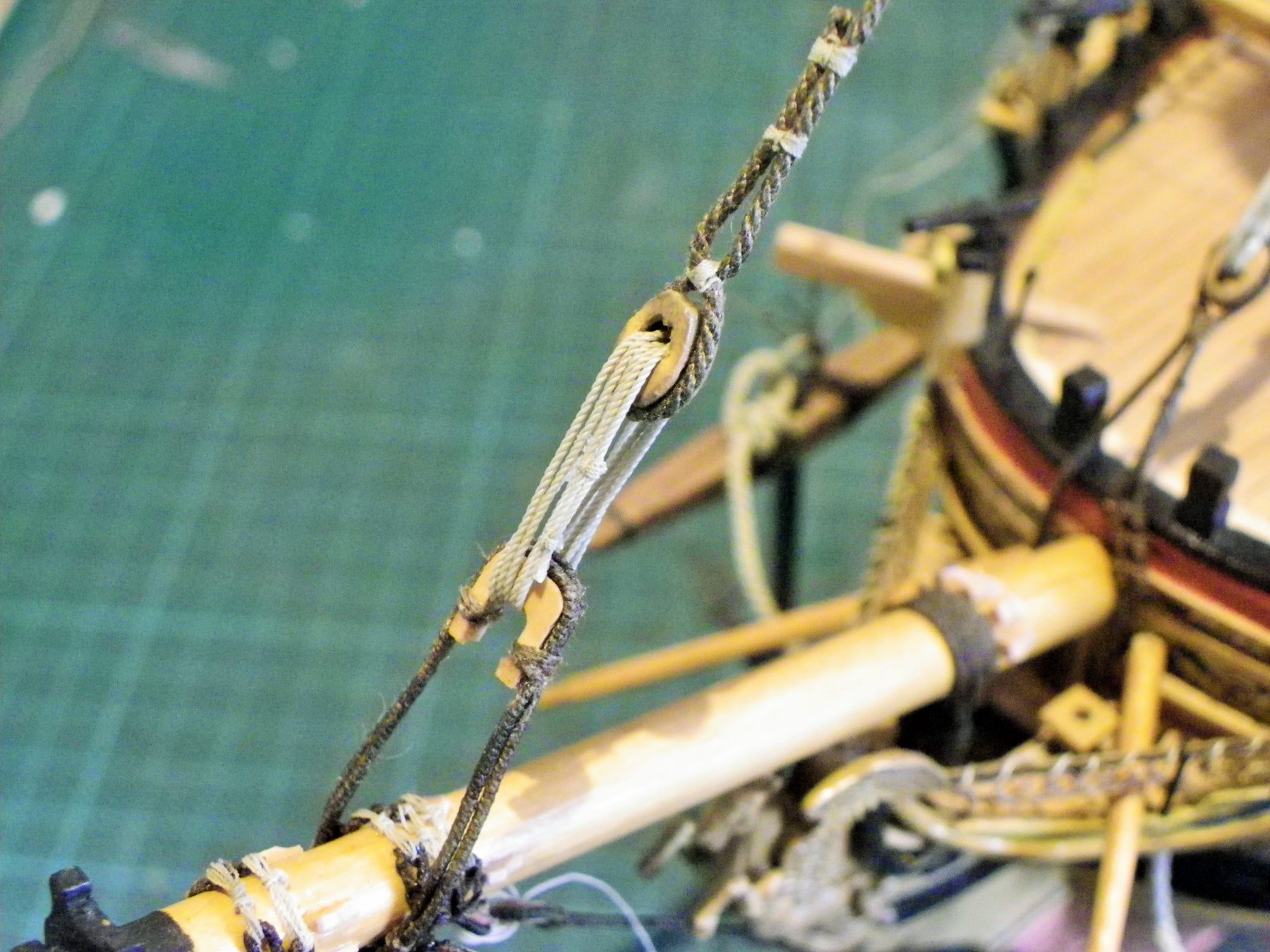
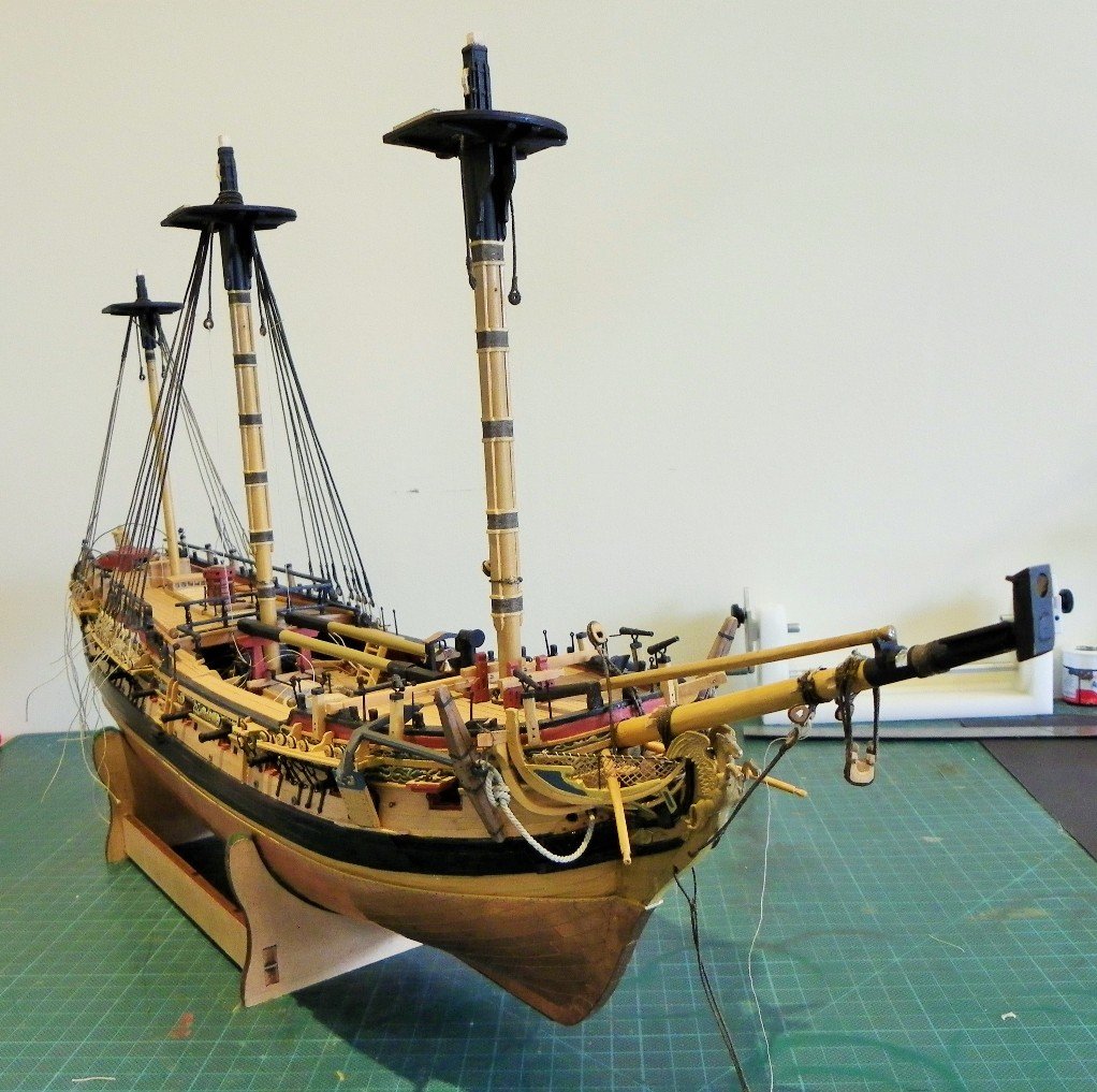
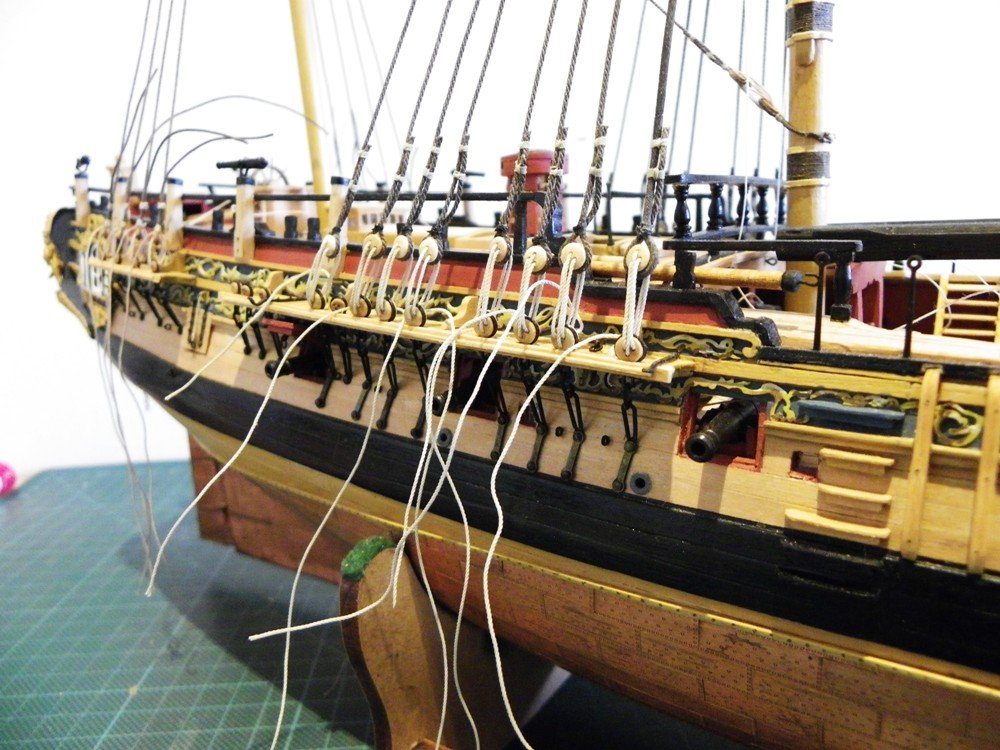
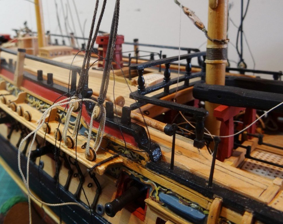
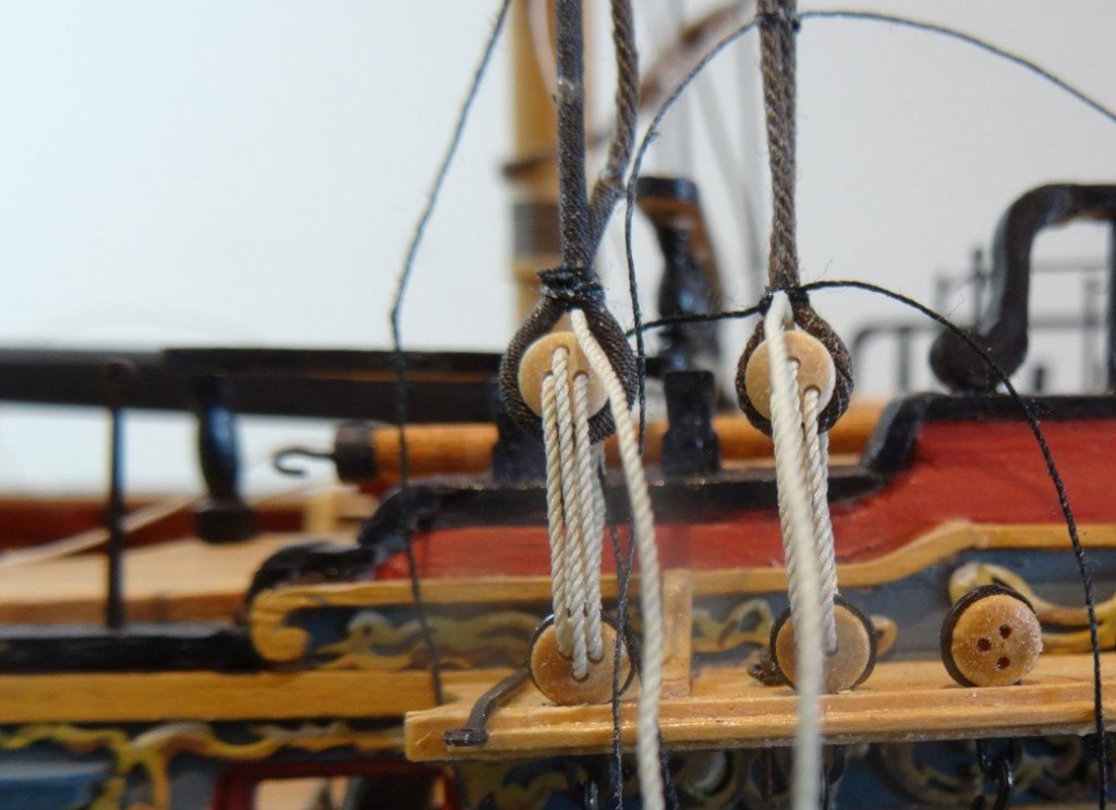
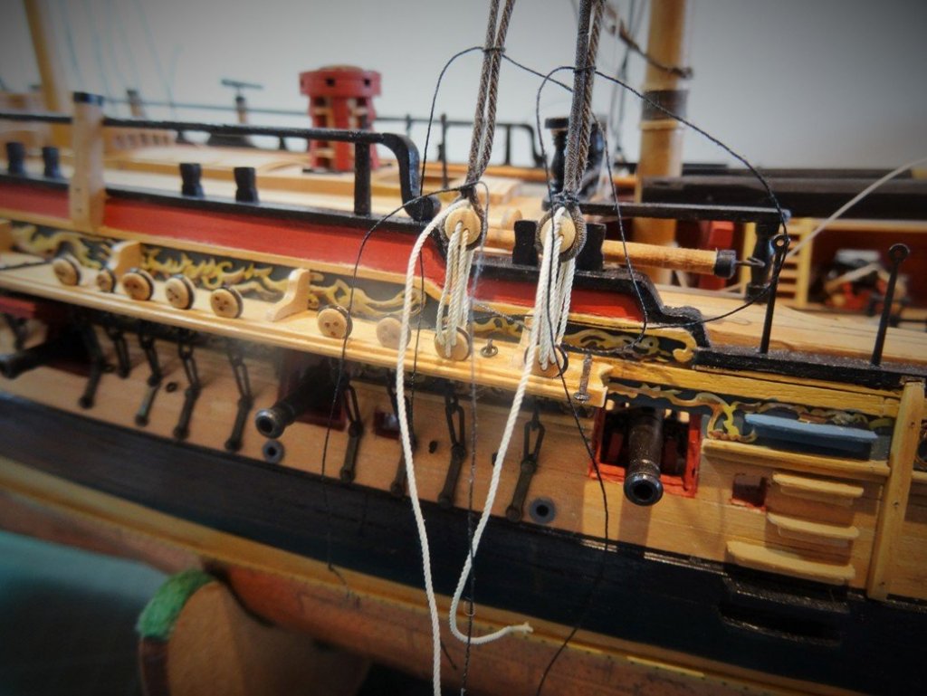
Bobstays. For these I am using 0.5mm line with a 0.25mm serving On my Pegasus the Inner Bobstay is 121mm long and the outer 156mm. These are just a guide as lengths are likely to vary slightly depending where the hearts are secured and the length of the lanyards. A little more tricky to rig Bobstays as the line has to pass thro’ the holes in the knee of the head before forming the splice and heart seizing. You can get away with a cheat here for the splice, simply bringing the two ends of the line together, knotting, glueing, and trimming, and hiding it within the hole in the stem. The seizing is done with 0.1mm line. Proper lanyards will not yet be fitted just in case I need to get access for something I haven’t yet thought of, never be too eager to finally tie things off, leave them as late as possible. The downward curve of the Bumkins can be seen here. I’ve just realised looking at this photo that I have fixed the lead sheet used to protect the Bowsprit from the wear of the Spritsail Yard slings the wrong side of the woolding. This has now been rectified. A final broadside shot. That’s about as much as I can do on the Bowsprit rigging at present. B.E.
- 366 replies
-
- 2
-
-
- pegasus
- victory models
- (and 2 more)
-
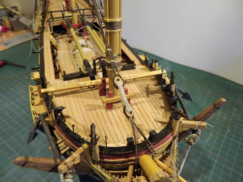
Fitting the Bowsprit Collars. The first heart on is for the Inner Bobstay, followed by the Starboard and Portside Bowsprit shroud hearts. Two cleats on the Bowsprit prevent it sliding down. Then comes the Forestay Collar and Open Heart. Forward of this by around 9mm at scale is the Outer Bobstay Heart. This requires four cleats to be fixed to the Bowsprit. Finally butting up against the outer Bobstay is the Fore Preventer Stay Collar and open Heart, which sits just behind the Jibboom chock. Using a needle to thread the lashing line between the two eyes of the heart strop. For this I am using 0.1mm Morope. What you see here is a deviation from the kit plans which show 6mm closed hearts for both Forestays, and 5mm deadeyes for the Bobstay and Bowsprit shrouds. In accordance with Steel I have used closed hearts for the Bobstay and Bowsprit shrouds, but he also mentions the use of deadeyes. Lees suggests that deadeyes were used up to around 1840, so I reckon either is acceptable. Before fixing the stop cleats I think it advisable to just check how the lines will sit so the stays etc are mocked up to get an idea. I made the cleats from some 1mm square boxwood strip. First time out of its case for Pegasus in a while. This post brings my log up to date and marks the three year point in the build still a long way to go. B.E.
- 366 replies
-
- 2
-
-
- pegasus
- victory models
- (and 2 more)
-
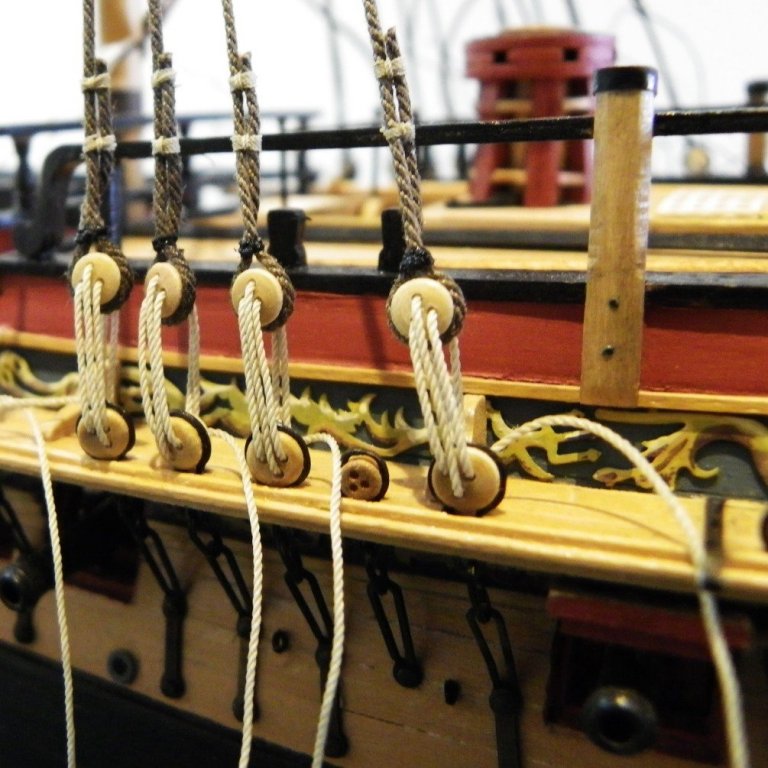
Fitting out the Bowsprit. This is the first build where I am paying proper attention to the finer points of rigging, as in stropping, seizing, and serving. Starting with the inner and outer bobstay collars, served scale line of 0.63mm ø is required. I will be using 0.5mm line served with 0.1mm line. The first task is to work out the o/a length of the strop. Tricky business this, first attempt too long, despite trialling it with line to gauge the length. Unfortunately the eyes met on the top of the Bowsprit with no space for the seizing. Finally 38mm of served length worked. A spot of pva was used to secure the line around the heart before seizing. The heart lies about half way between the Figure and the Bowsprit cap. Next up the Bowsprit shroud collars; similar, but with one leg shorter than the other to allow the heart to sit in the right position whilst maintaining the seizing on top of the bowsprit. For these I allowed 40mm of served line. At this point I’m starting to lose the will to live, and hanker back to those carefree days when stropping and attaching blocks was a simple matter of any which way. Onto the Forestay and Fore Preventer stay collars. The method I’m using for making the strop loops is from the ffm and involves leaving long ends to the serving line and short cut ends to the main line which are brought together and glued to form the ring. The serving lines are then turned around the ‘glued’ section to form the ‘splice’. The strop ring is completed. Forestay collar 13” Open heart (5.5mm) 5” line (0.63mm dia) The collar is double and fits around the open heart. A scale 27’ of 5” line is used. (0.63 ø line with 128mm of length.) For this I’m using 0.5mm line with a 0.25mm serving. Held in position for seizing the strop to the heart. The completed Forestay Collar. Fore Preventer Stay collar 10” Open heart (3.96mm) 4” line (0.5mm dia) The collar is again double and fits around the open heart. A scale 27’ of 4” line is used. (0.50 ø line with 128mm of length. For this I’m using 0.5mm line with a 0.1mm serving. The Completed Fore Preventer Stay Collar. Moving on now to see how they look on Pegasus. B.E.
-
Moving on to the closed hearts, the first consideration are the hearts for the bobstay and Bowsprit shroud collars. Heart sizes according to Steel. Inner Bobstay collar 6” closed heart (2.5mm) 5” circ line(0.63mm dia) Bowsprit Shrouds 6” closed heart (2.5mm) 3½” line (0.44mm dia ) These should be far smaller than the kit provided items, leaving little option but to make them. Fortunately there are only eight hearts to make. These were all done by hand out of boxwood strip, after abortive efforts trying to make them on the Mill. This is the ensemble of tools used for the purpose. Small holes drilled in triangular pattern, the outline heart drawn on, the hole cut out with a scalpel and enlarged using a triangular shaped needle file. One side of the heart cut and filed to shape, the piece then removed and shaped whilst secured on the needle file. The groove around the edge marked with a micro saw cut and enlarged with the sharp edge of a needle file. The completed set took three or four hours to make. Also included here are a couple of the 6mm kit provided hearts for a size comparison. The boxwood versions are 3.5mm. These will be fettled a little more before use. One final tip on Closed hearts, those triangular deadeyes for 17th century ships can be converted easily to hearts. Removing the centres along the line of the holes and you have a heart. These are Mantua boxwood deadeyes but only supplied in 5mm and 10mm sizes. (These are the 5mm versions) Still a useful option. I can now begin attachment of the collars. B.E.
- 366 replies
-
- 1
-
-
- pegasus
- victory models
- (and 2 more)