HOLIDAY DONATION DRIVE - SUPPORT MSW - DO YOUR PART TO KEEP THIS GREAT FORUM GOING! (89 donations so far out of 49,000 members - C'mon guys!)
×
.JPG.ca33079f5815b861e67b9c2cccd37982.JPG)

Blue Ensign
-
Posts
4,566 -
Joined
-
Last visited
Content Type
Profiles
Forums
Gallery
Events
Everything posted by Blue Ensign
-
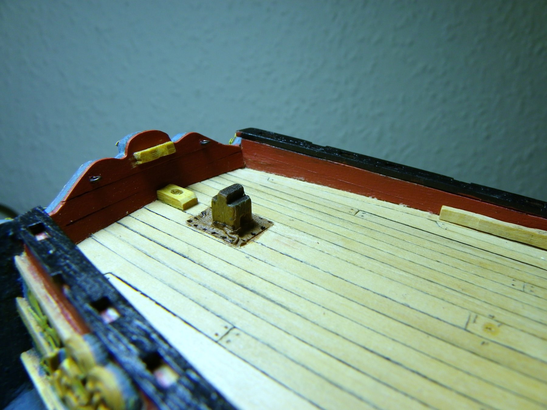
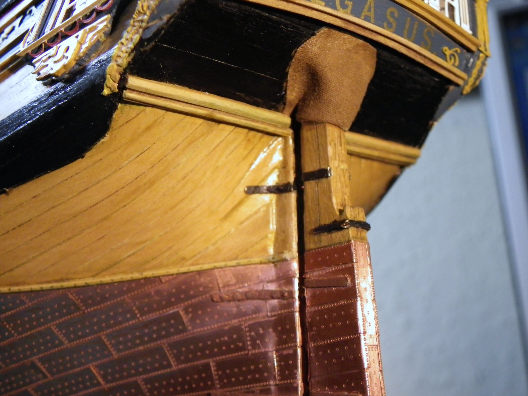
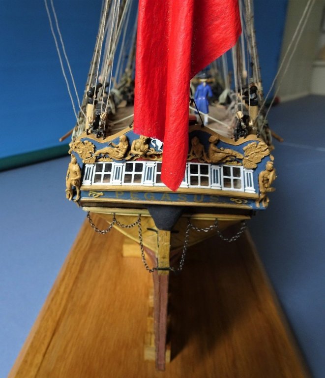
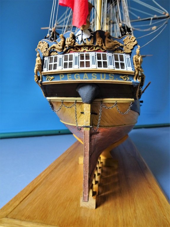
 There was usually a Rudder Coat fitted to prevent ingress of water thro' the counter. The Rudder Coat was a loose fitting bag like cover made of tarred canvas nailed to the rudder head and counter. Tricky little beggars to make at model scale but you will find examples around the model builds. Where the Rudder head came thro' the deck another small tarred canvas cover would be secured around the head and to the deck to reduce any water ingress to the deck below. The photo's below show the arrangement I used on my Pegasus build. Rudder coat in course of fitting. Canvas cover around rudder head, on Pegasus an additional cover was built over the rudder head to further protect it. B.E.

-
Looking splendid in those two update photo's on the previous page Michael, would make a fine display model even as she is. B.E.
-
Hi Ken, I upload photo's directly from my computer photo files, and they appear along the bottom of the log entry I am making. You can do this for all the photo's you wish to include in a particular log entry. I type in the blurb for the log, and then move the cursor below the line of print and click on the photo I wish to select which then appears in the body of the log. Again move the cursor below the photo and begin writing again in the body of the log, and so on. Hope this helps. B.E.
- 3 replies
-
- 10
-

-
Beautiful result Tony, and your log accompanied as always by clear explanations and how to's. Great job B.E.
- 132 replies
-
- 3
-
-
- triton cross-section
- cross-section
- (and 1 more)
-
Thanks once again Guys, there will be one more photo - when she is encased and placed in the spot reserved for her. In the meantime I am using the huge collection of photo's amassed over the past seven years to put together a large format 120 page photo book record of the build. Regards, B.E.
- 366 replies
-
- 9
-
-
- pegasus
- victory models
- (and 2 more)
-
What a stunning sight It just gets better and better. B.E.
- 2,625 replies
-
- 5
-
-
- kaiser wilhelm der grosse
- passenger steamer
- (and 1 more)
-
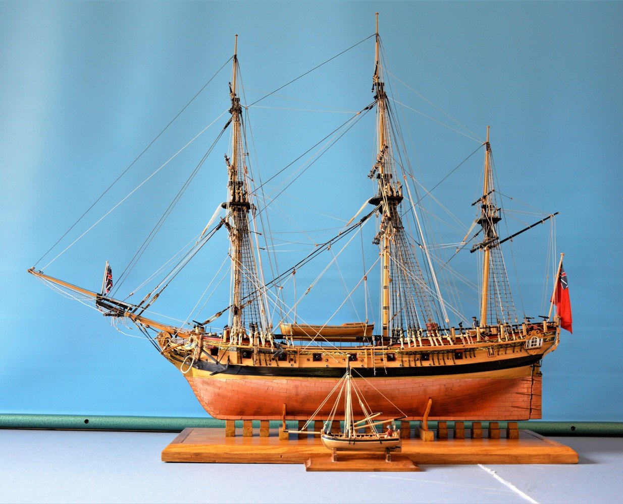
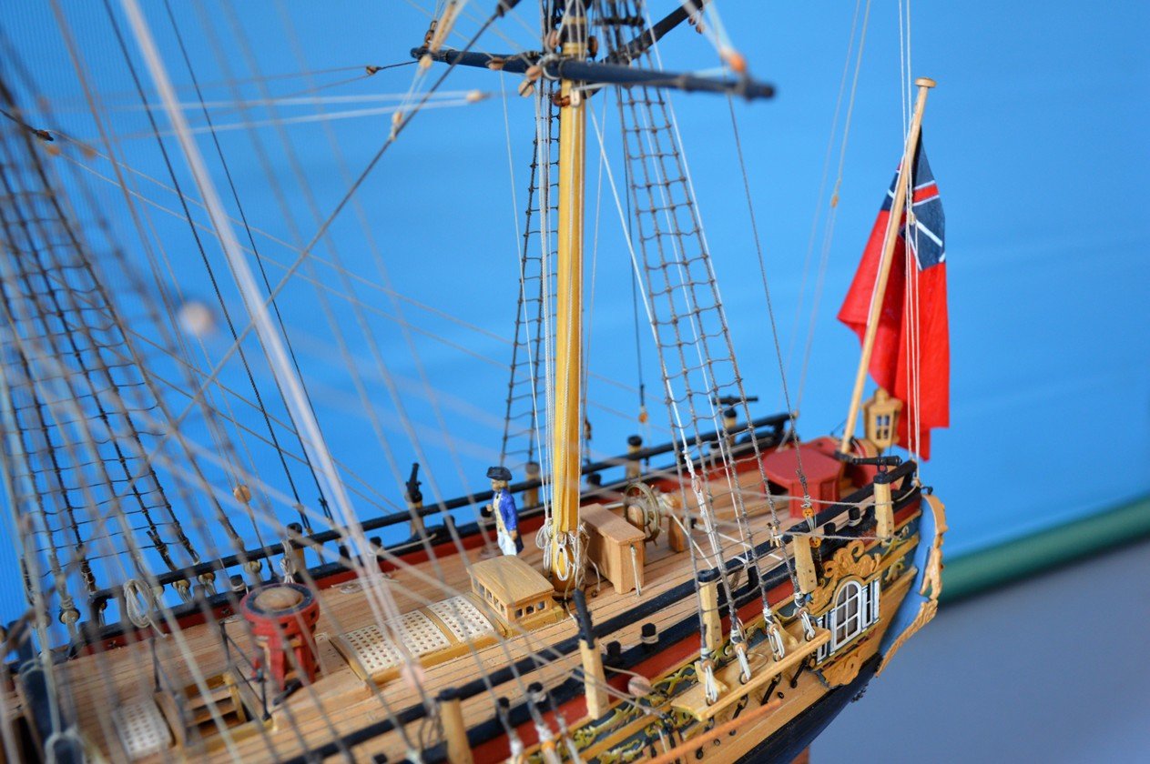
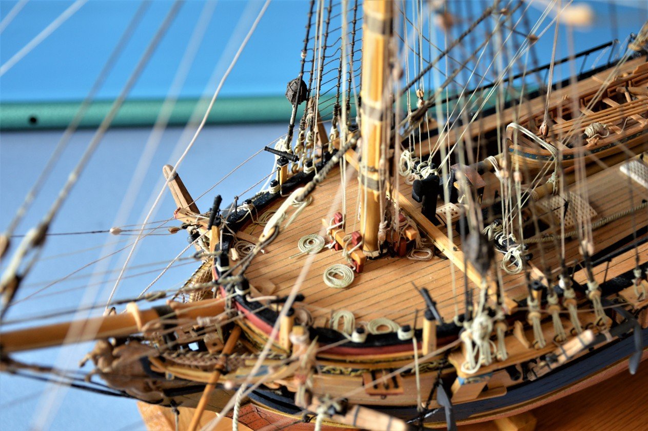
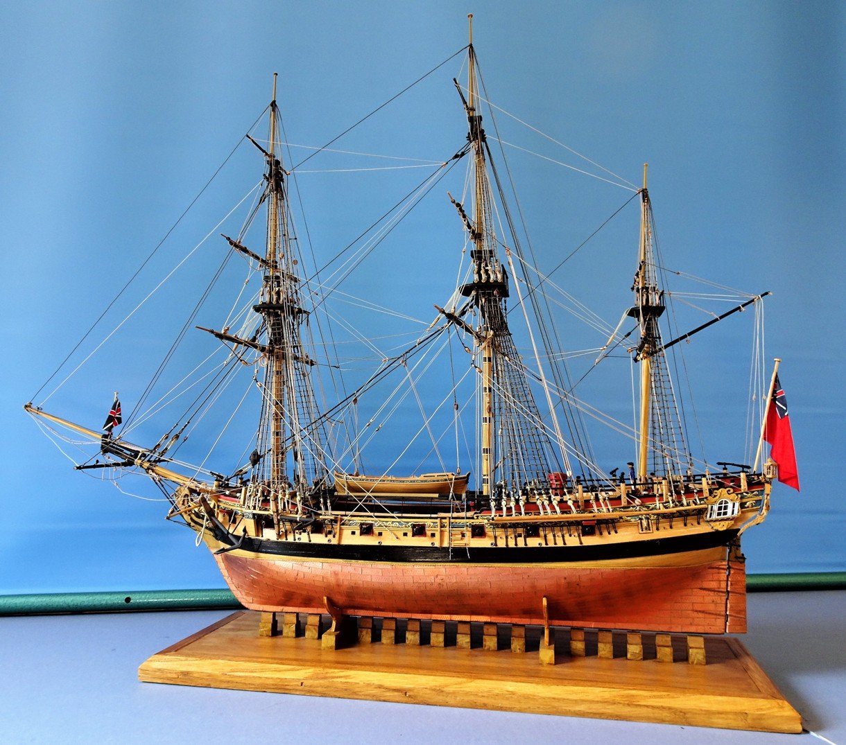
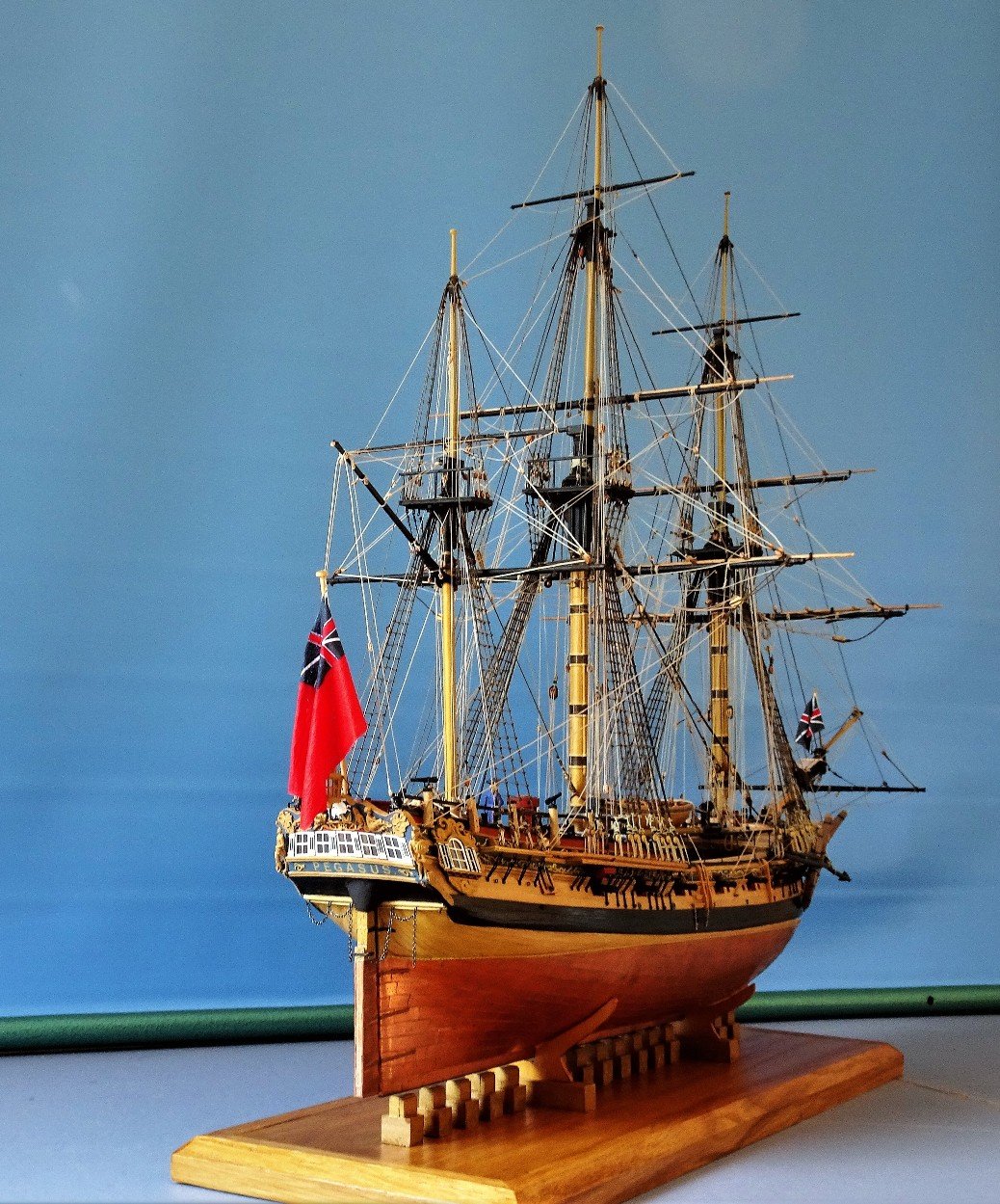
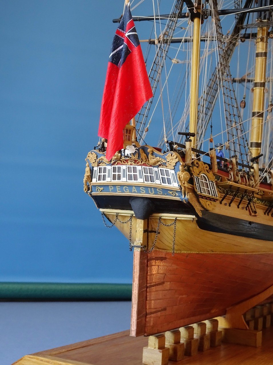
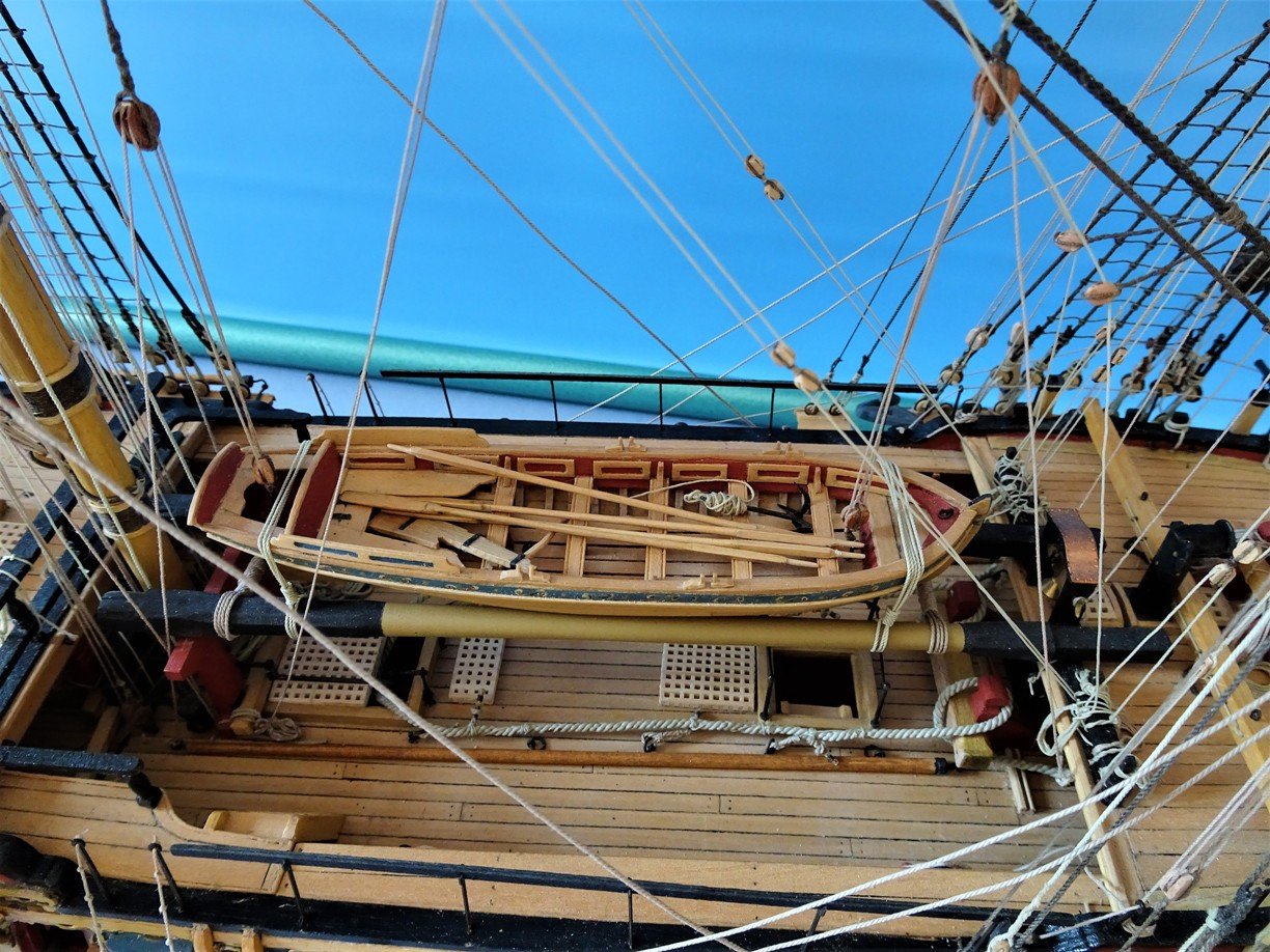
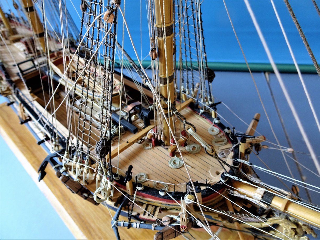
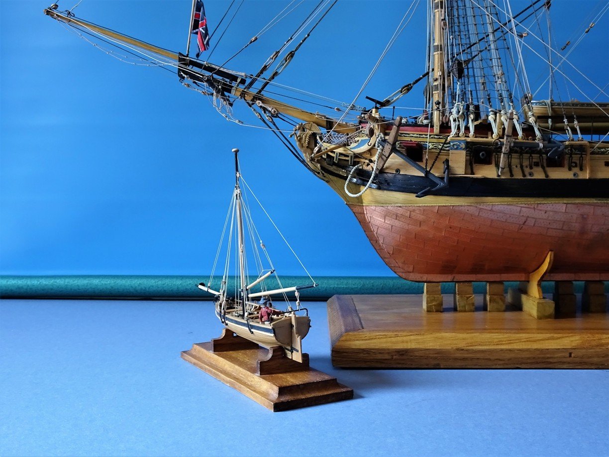
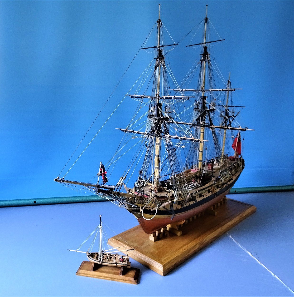
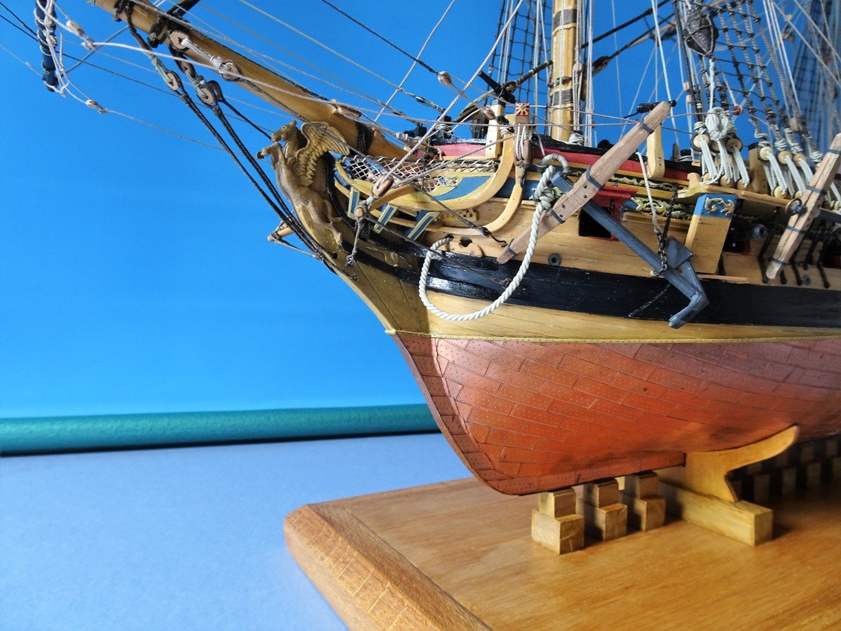
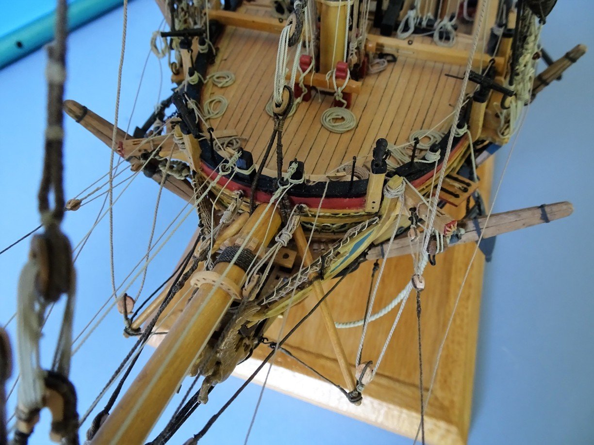
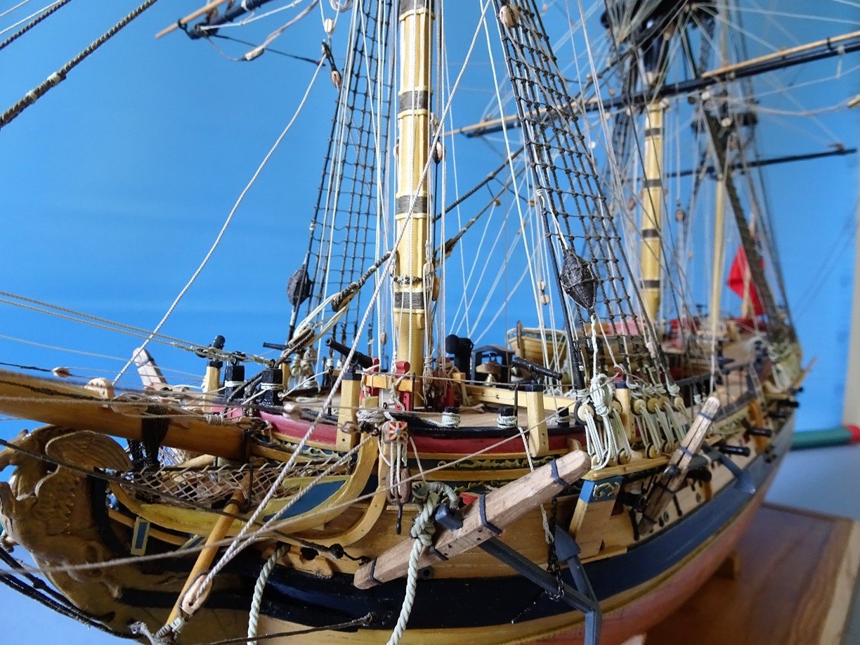
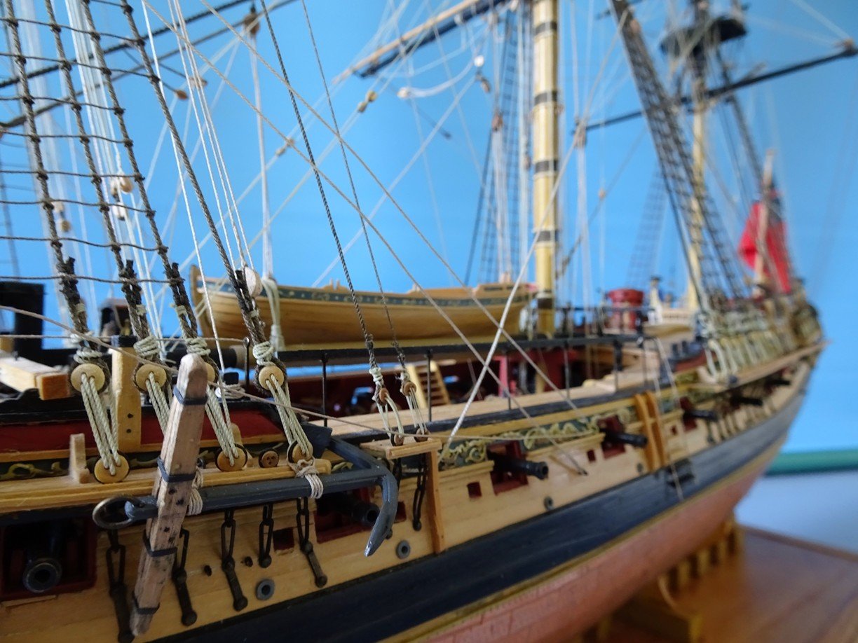
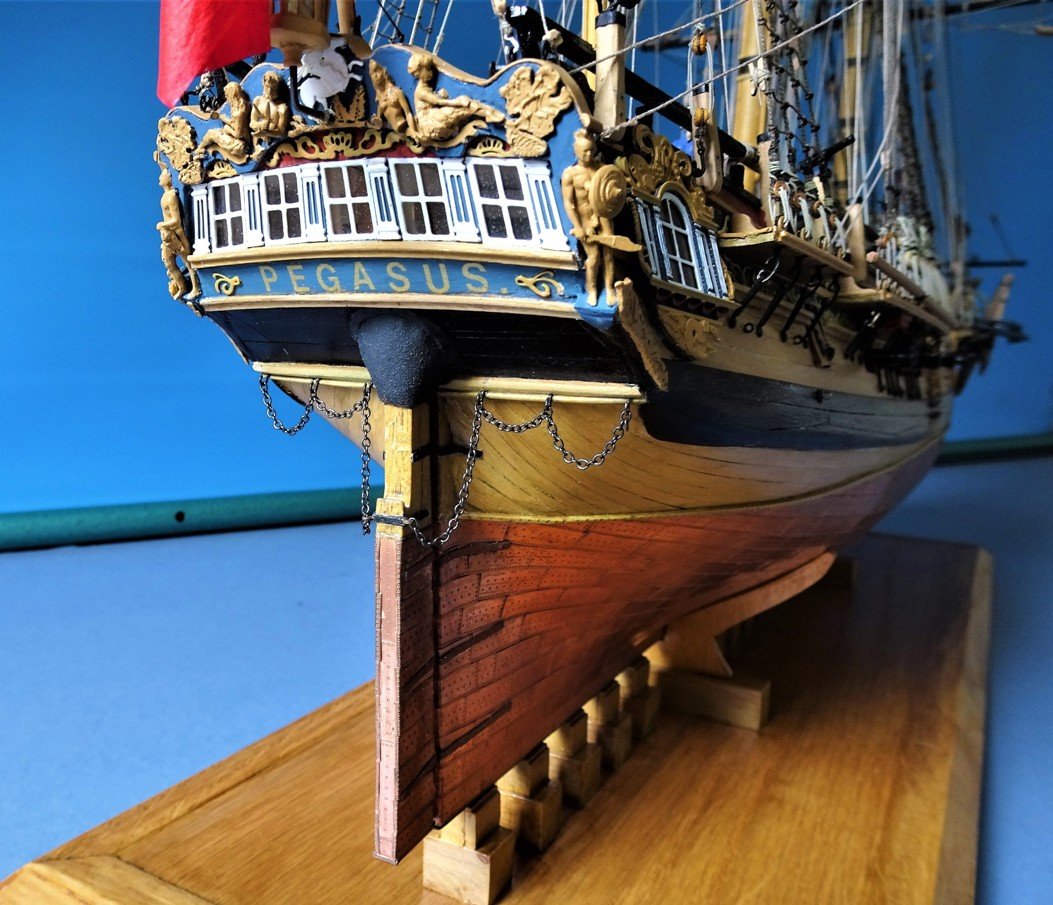
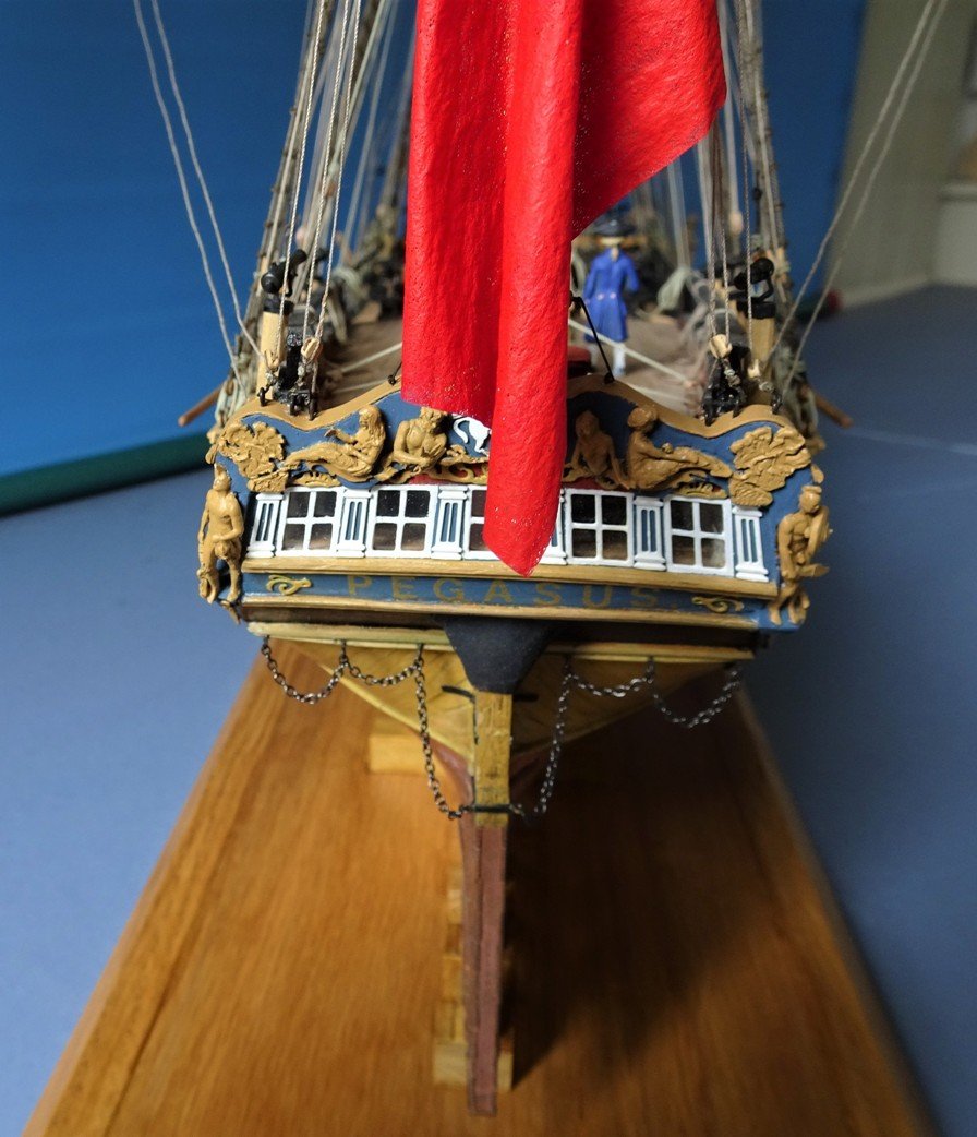
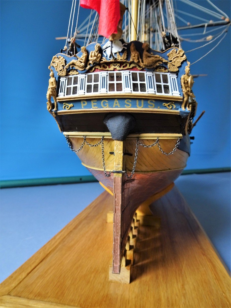
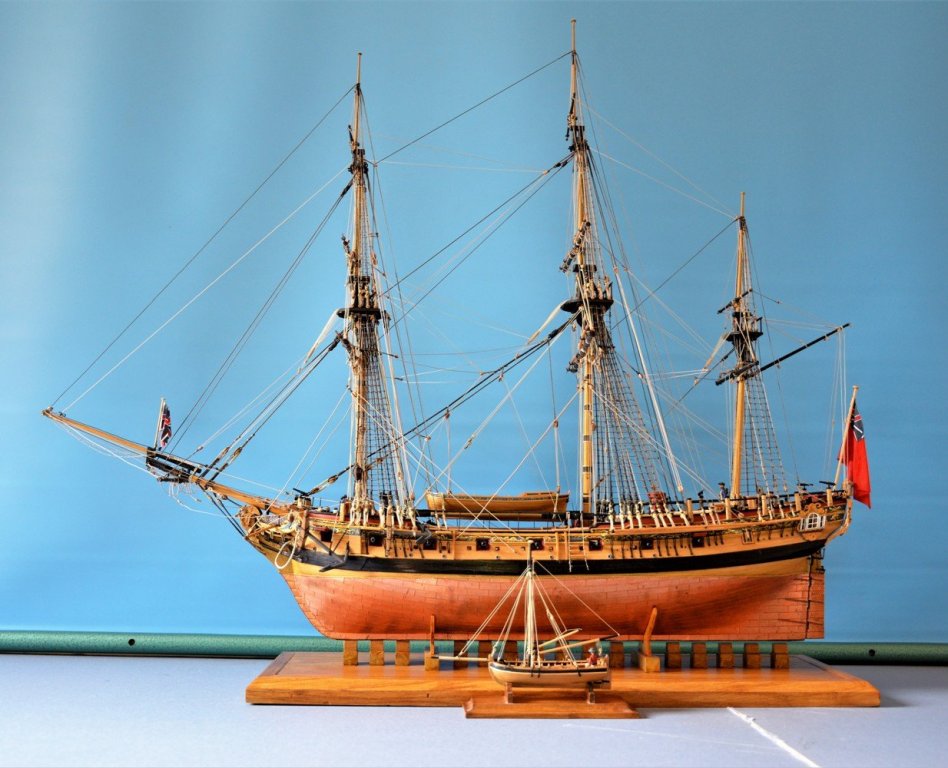
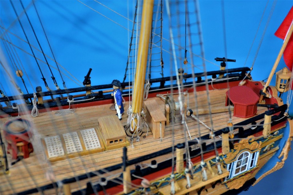
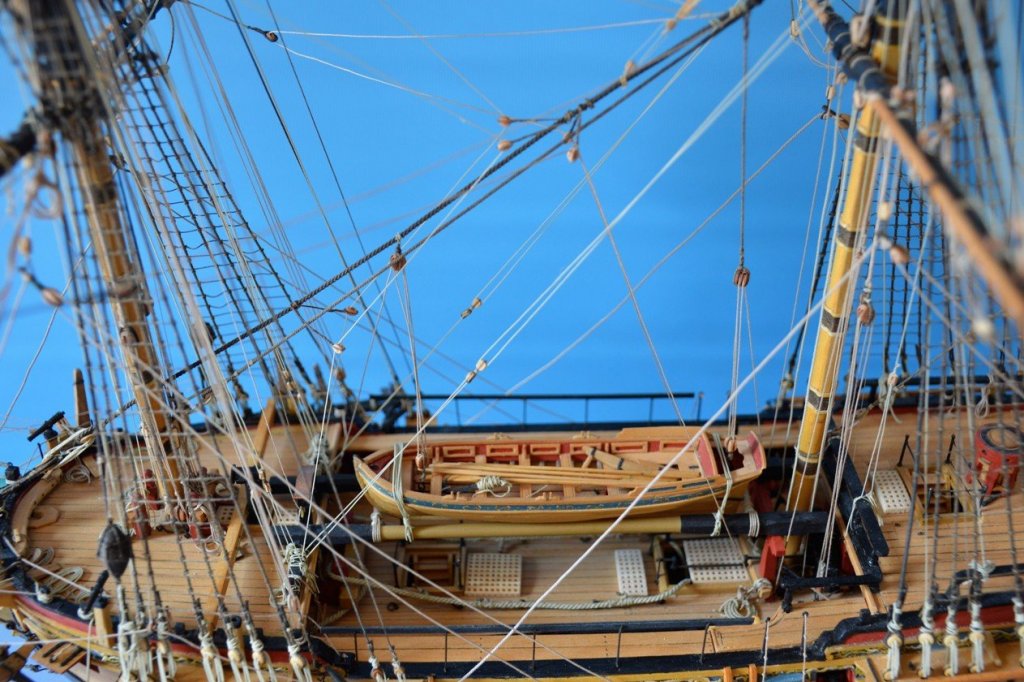
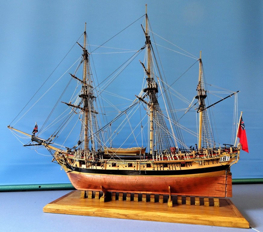
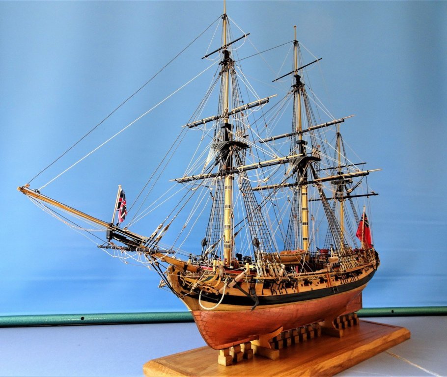
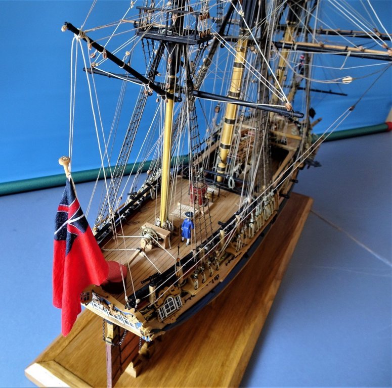
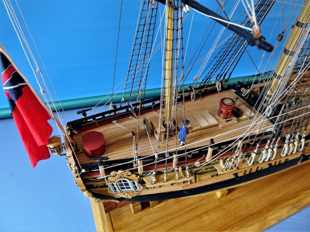
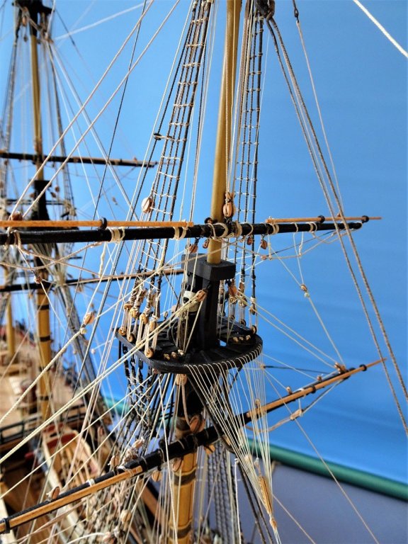
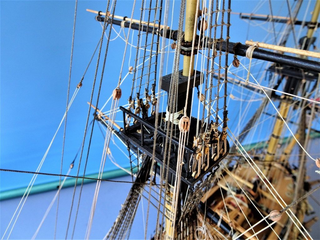
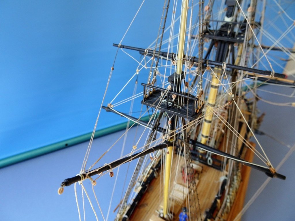
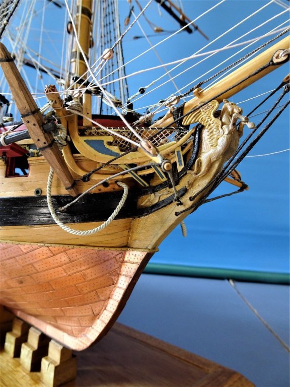
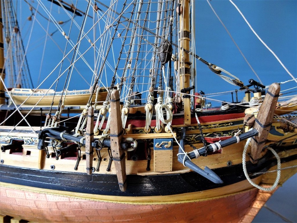
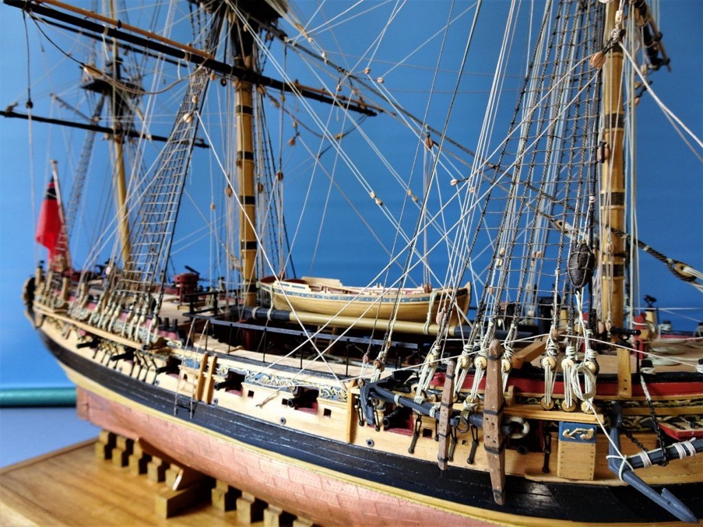
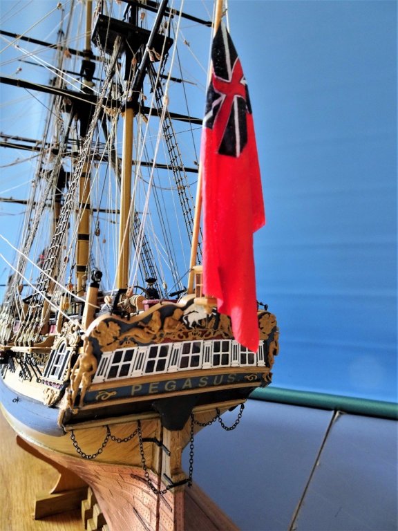
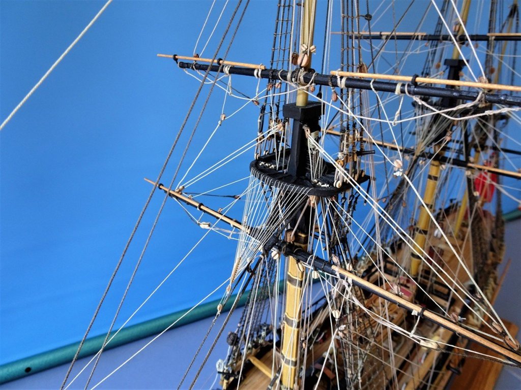
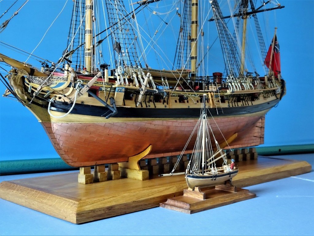
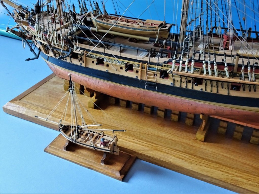
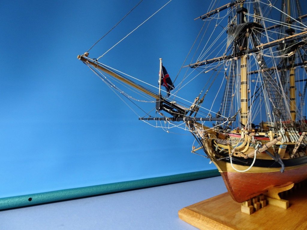
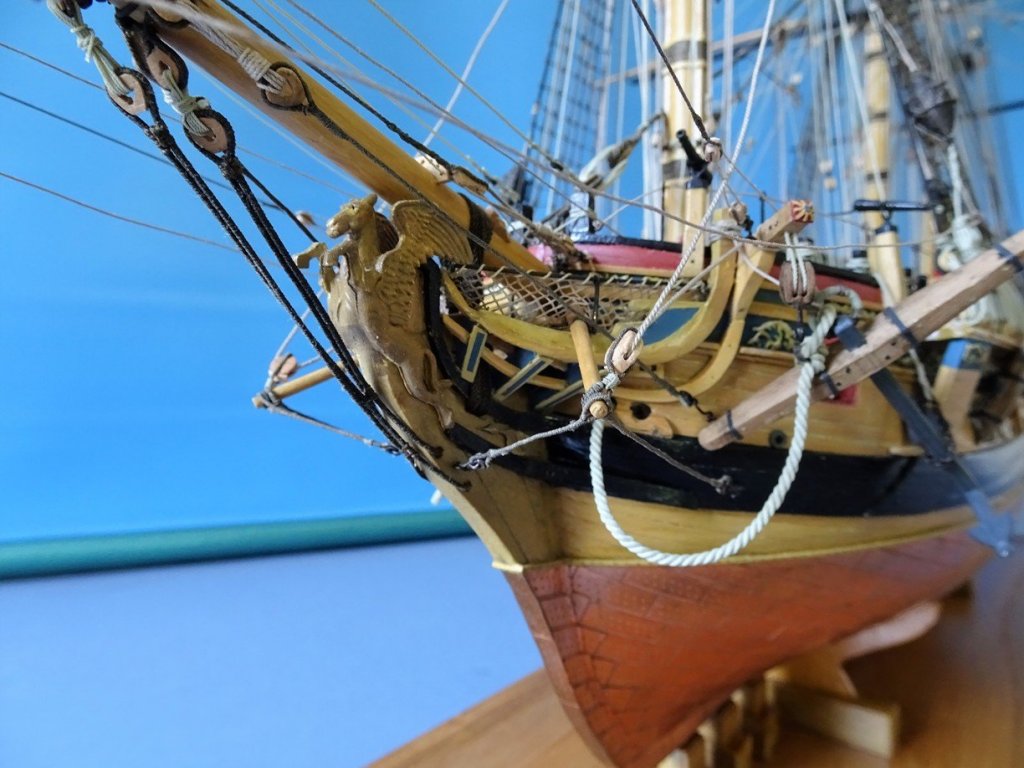
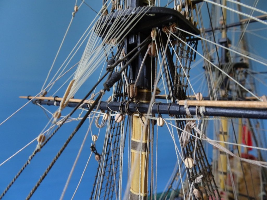
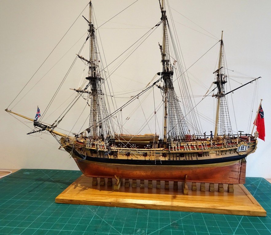
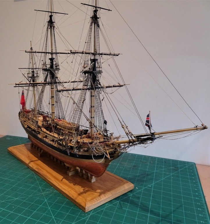
Cheers Guys, These are the completion photo's, before Pegasus is enclosed in her case, which is still wip. firstly the detail shots: The Rigging shots With the Longboat, which will be placed within the case, but not on the temporary stand as shown below. Overall shots B.E.


- 366 replies
-
- 36
-
-
- pegasus
- victory models
- (and 2 more)
-
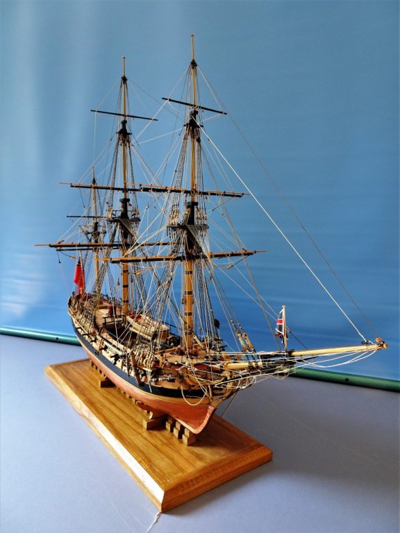
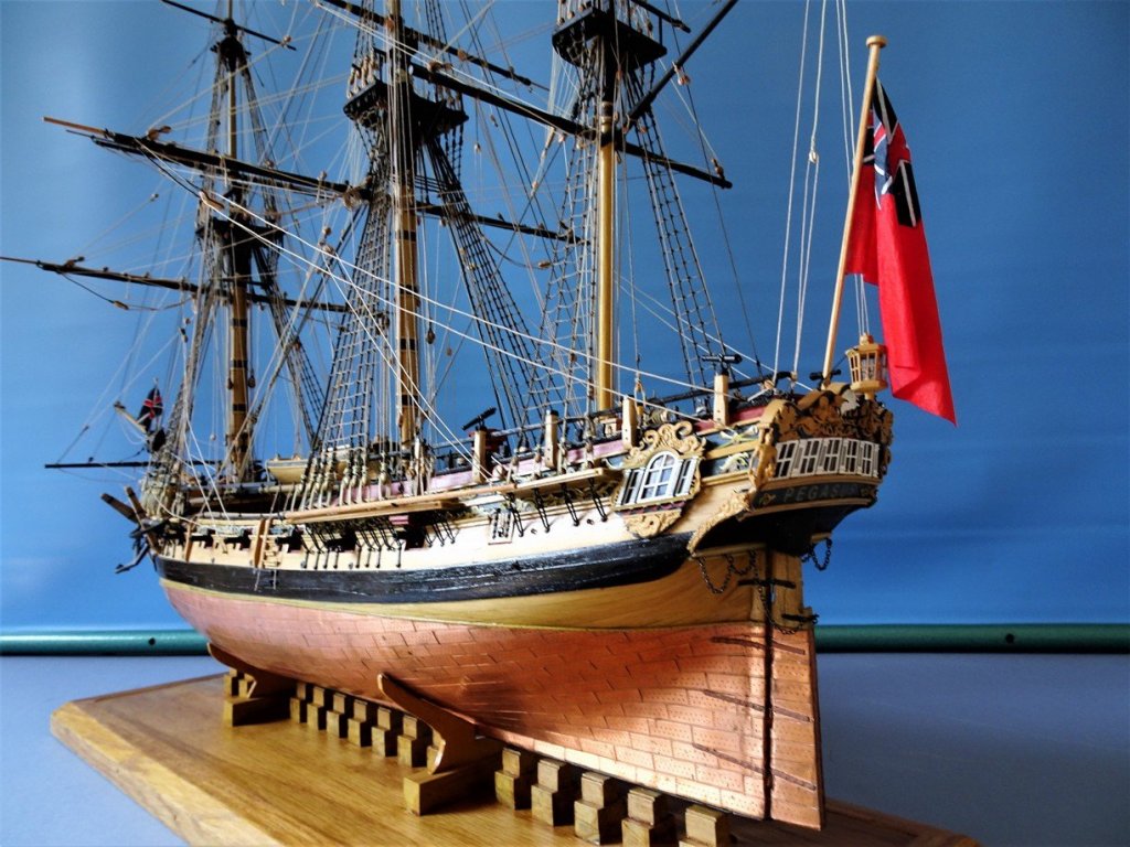
Thoughts about Pegasus This post concludes my build of seven years, and one I have thoroughly enjoyed, as I have enjoyed sharing this journey with my fellow modellers on MSW. The beauty of this model is that it is large enough for detail but not so big that it raises any serious display issues. It is also highly decorative and is placed in the period before the Nelson chequer and austerity removed much of the decoration from Georgian ships. Victory models are the ‘posh’ end of Amati a bit like Lexus and Toyota, and the basic kit produces an attractive model of this pretty bijou Frigate. Thanks are due to Chris Watton who designed the kit, and to Amati who produced it. Even so, most commercial kit manufacturers make simplifications to extend the appeal to a greater range of modeller ability, and include somewhat out of scale and generic fittings and Amati is no exception. Much of the enjoyment for me has been in enhancing the kit by use of different materials and fittings and bashing it about a bit with a fair amount of scratch building. Apart from the basic skeleton and some of the brass etch, very little of the kit provided material and fittings have been used, and I am quick to gloss over the additional costs involved. Outside sourced materials and fittings. Boxwood strips and section http://www.originalmarquetry.co.uk/product_details_335.htm Rigging blocks and associated attachments https://www.syrenshipmodelcompany.com/ http://www.model-dockyard.com/ Rigging line. https://www.syrenshipmodelcompany.com/ http://home.foni.net/~agondesen/left.htm Guns http://www.rbmodel.com/index.php?action=products&group=023 Anchors http://www.jotika-ltd.com/Pages/1024768/Fitting_Front.htm lantern https://www.syrenshipmodelcompany.com/ Dowels- Ramin for lower masts Various suppliers - check online Additional brass etch. http://www.jotika-ltd.com/Pages/1024768/Fitting_Front.htm Scratched modifications Stern Gallery style and decoration. Great Cabin interior. Beneath the Foc'sle deck. Foc'sle rail and belfry. Quarterdeck rails. Head works and Cat heads. Capstans, Gallows, and pumps. Hatch Coamings Swivel gun posts. Masts and yards. Scratched additions Galley Stove, Galley Chimney. Binnacle, Steering stanchions, and Tiller. Rudder head Cover, Rudder coat. Clerestory Style Companion top. Hatch railings, Gang planks, Fish Davit. Pinnace and Long Boat. Swinging Booms, Flag staffs and Ensigns. Reference Works. For references I primarily used Steel and the Fully Framed book series by David Antscherl, cross referred to Lees, and Marquardt. Particularly in relation to Masting and Rigging I used Steel to work out the dimensions and line sizes. http://www.hnsa.org/resources/manuals-documents/age-of-sail/the-elements-and-practice-of-rigging-and-seamanship/ I am quite pleased with the end result of my build and there are only a couple of things I would have done differently were I starting now. 1) I would have reduced the width of the first(Bridle) port to make it narrower than a standard gun port. 2) I would have included the bands of top and butt deck planking on the upper deck. I would also hope to improve the finish in some of the areas where my knowledge exceeds my skill to carry it out. I will finally post some completion photo's in the next few days. Thank you all for following along. Blue Ensign 8th April 2017.
- 366 replies
-
- 21
-
-
- pegasus
- victory models
- (and 2 more)
-
Hi Christian, I have had a look in the AotS book on Diana and David White does not show additional seats of ease in the aft corners of the headworks, but that space on your model is exactly where such seats would be fitted. David Antscherl in Vol 11 of tffm (Para 11.33) does indicate fitting of these additional seats as an option for the Swan model. I didn't on my Pegasus because the headworks are quite small and a Sloop is a much smaller ship than a Frigate. In the book are photo's of the Frigate Minerva model (Rogers Collection) which clearly shows these additional seats of ease, and my inclination would be to fit them over that space or at least fill it in with additional grating strips. Regards, B.E.
-
Beautiful work Christian, the head works look splendid Is there a second set of seats of ease to be added where there is a space aft of the gratings? I think the 'False' Rail above that area was in part to provide a modicum of security and privacy for users of the facility. B.E.
-
That is quite some build you've taken on there Anton, great job on the gunports, a tricky job that gives me the yips just thinking about it. Well done B.E.
- 322 replies
-
- 4
-
-
- sergal
- sovereign of the seas
- (and 5 more)
-
Very pretty Kurt, reminds me of the launches of our English Lake District. However, my interest leans towards the 18th century, and the offerings of our vey own Chuck are a very strong draw. B.E.
- 366 replies
-
- 2
-
-
- pegasus
- victory models
- (and 2 more)
-
Thank you Christian, Michael, Nils, Anton, Bob, Steve, Mark, Grant, Tigersteve, and Kurt, and to those who hit the 'like ' button. @ Michael - There won't be any framing around the case, a simple acrylic cover to fit over the base. I guess the re-issued log uninterrupted by comments is a Kindle edition book of sorts. @ Bob - Steady on there Bob, there are many builds on here that I rate far higher than mine, your own great models included, but very nice of you to say so, you bring a blush to my cheek. @ Kurt - Nothing finally decided as yet, except it won't be a three masted square rigger. Something like a larger scale smaller boat is probably favourite, but I need to get Pegasus off my work bench and under cover before I begin. Once again many thanks to those who have followed my Sloop adventure. B.E.
- 366 replies
-
- 6
-
-
- pegasus
- victory models
- (and 2 more)
-
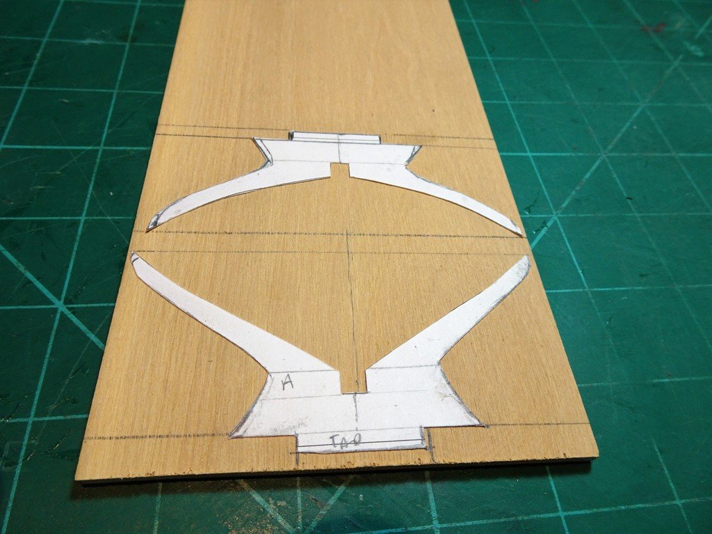
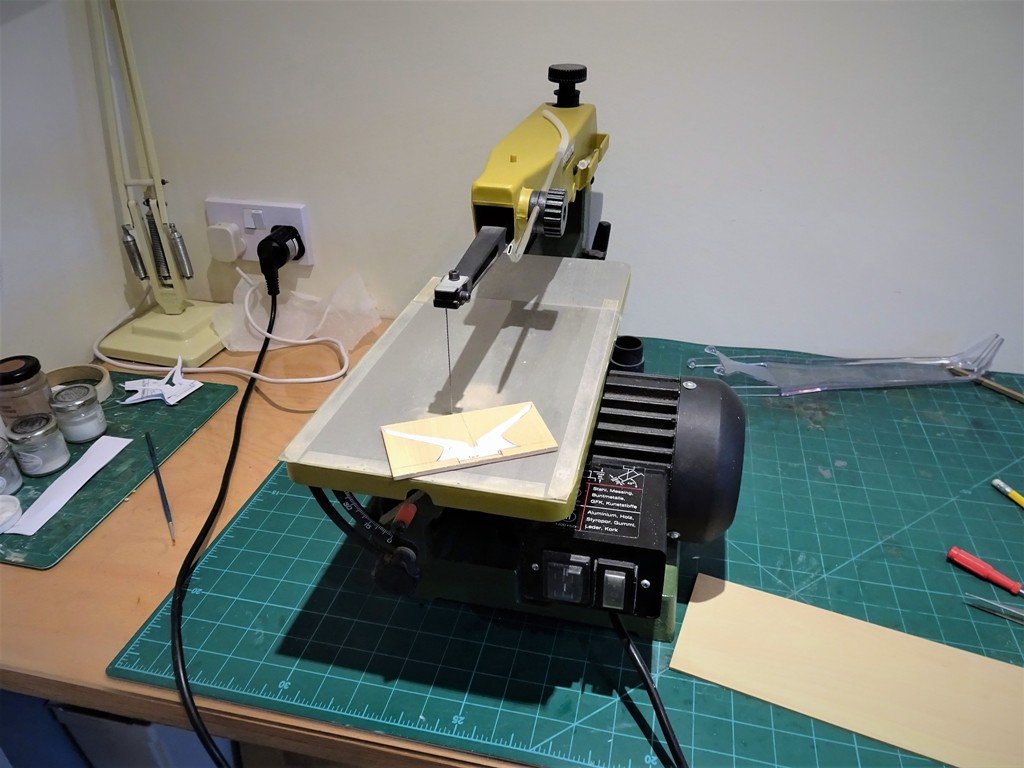
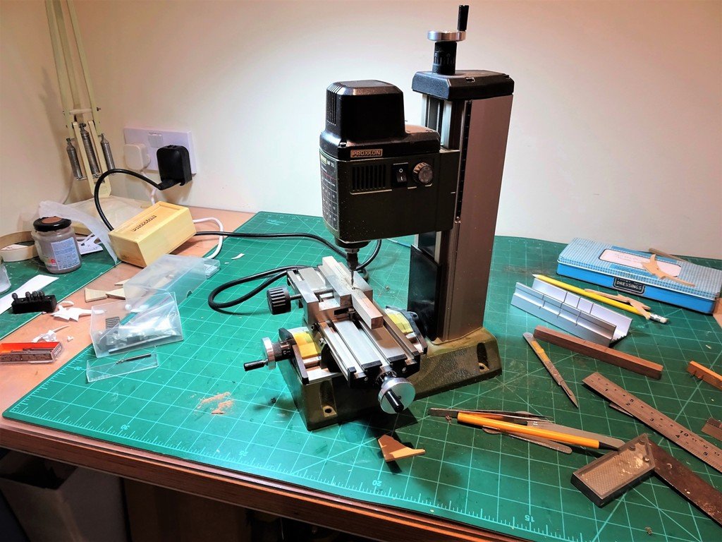
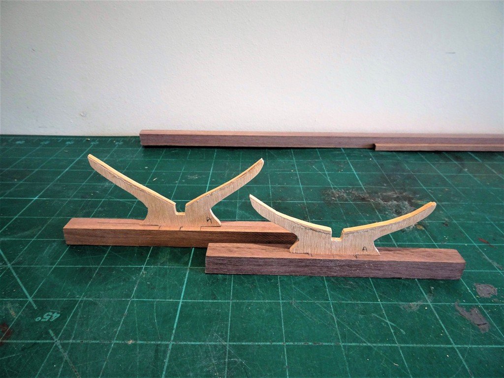
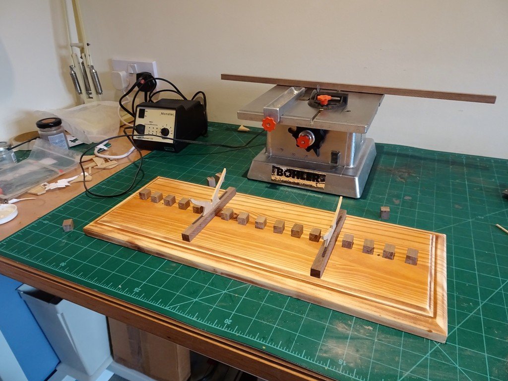
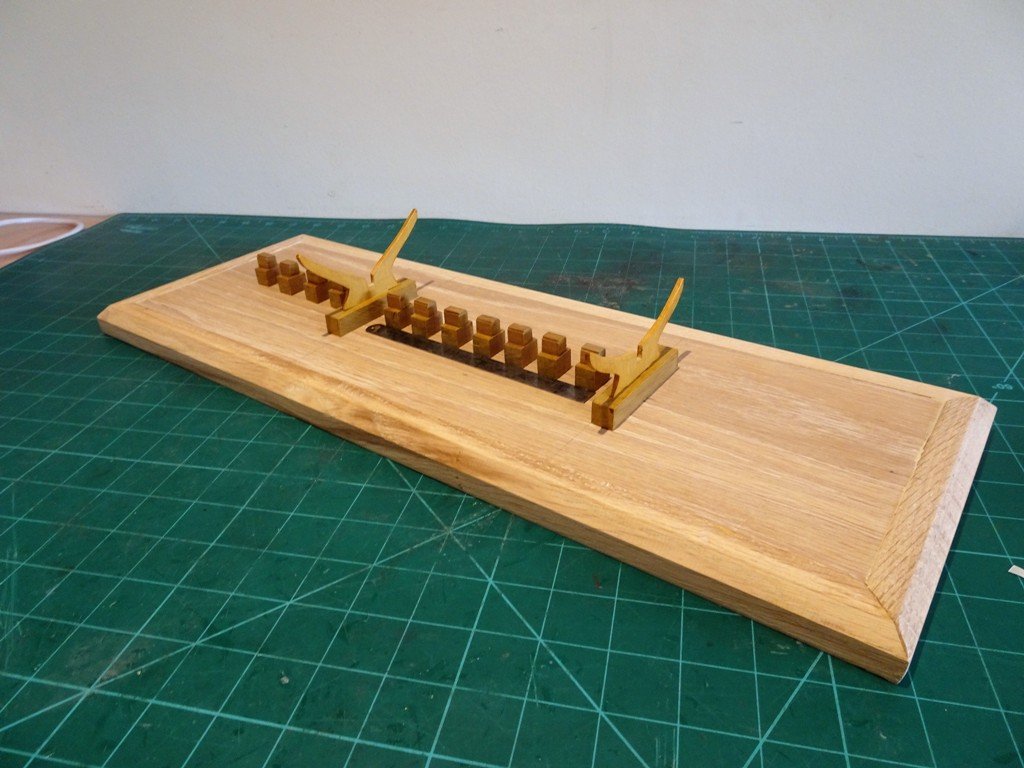
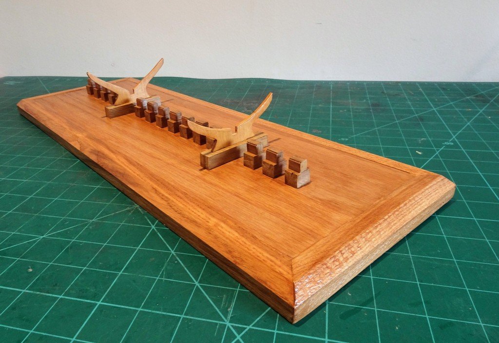
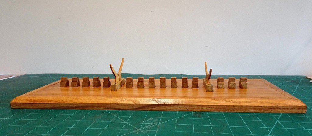
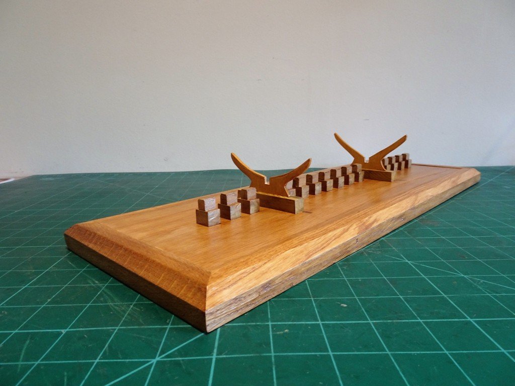
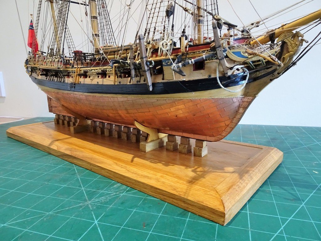
Making a Base for Pegasus The cradles are cut from some 1/8th Boxwood sheet stuff having used the kit stand as a template. For this the beast has to come out. Two lengths of 12mm square walnut are slotted to take the cradles. The little miller is very handy for this. The basic cradles completed. My preferred option is for a base where the model sits on stylised Keel Blocks supported by cradles of the minimum profile sufficient to give the model stability. The Bohler makes quick work of cutting the keel blocks from 12mm section Walnut, which will be topped by 9mm section blocks on which the keel will sit. This is not the proper base, just an old drawer front used for the purpose of setting out. The model sits on a plain oak base which will be contained within a protective acrylic case. Setting out the keel blocks. The base completed. I now need to have the protective case made. This is not unsubstantial being 780mm long x 640mm high x 330mm wide. In the meantime I will continue to fuss over the model tweaking and cleaning. B.E.
- 366 replies
-
- 12
-
-
- pegasus
- victory models
- (and 2 more)
-
Hi Jason, thank you for your kind words. As far as the Great Cabin is concerned access is most definitely there - provided you are only 25mm tall. Hi Martin, hope you do get some progress in the boatyard this weekend; Cephalic feline nature eh, you plains folk surely are Highfalutin. for myself I'm off to the Cotswolds for a spot of R&R. B.E.
- 366 replies
-
- 2
-
-
- pegasus
- victory models
- (and 2 more)
-
No need to go to the other place Martin, the detail is here on page 3, post 72 of my log. The Cathead should butt up against the Main rail of the head works and during the process of fixing the cathead it is worth checking they sit right. On Pegasus the Main rail is a pre-shaped piece of walnut so it is an easy matter to blu-tack it temporarily in place before the cathead position is fixed. Cheers, B.E.
- 467 replies
-
- 1
-
-
- fly
- victory models
- (and 1 more)
-
Thank you, Don, Lawrence, Joe, and Mike for your most generous comments, much appreciated. @ Lawrence, served brass wire comes in very handy for a number of tricky little rigging requirements, and Catharpins are one of the best examples. @ Mike, I didn't repost the log twice, just in two halves. Fortunately the first half was a straight copy and paste from another forum, and the second half (Masting and Rigging) from my word/photo files, which were in a reasonable order but still took several day to complete and proved the most tiresome. Otherwise I doubt I would have had the heart or inclination to start again. I now live in fear of the 'delete' button ps: Have you changed your tag name from 'Landlubber Mike? B.E.
- 366 replies
-
- 6
-
-
- pegasus
- victory models
- (and 2 more)
-
I'm with the programme Martin, just because it's hidden is no reason not to do it. Mrs Shires W is generally supportive of my modelling activity, but having read the frank disclosure by Mrs Prairie W, I now begin to wonder why. She did once express an interest in making an Airfix Spitfire (had to be an Airfix) and indeed started it, when I asked which Mk she would like I was promptly told not to get nerdy! just get her a Spitfire. Still on with the show - don't forget to get the Catheads the right way up, and you will need to temporarily fit the main head Rails to assist getting the position right. Cheers, B.E.
- 467 replies
-
- 1
-
-
- fly
- victory models
- (and 1 more)
-
Our respective Mrs W's seem to have the same outlook towards our modelling efforts, but that's not the point is it, although on a practical level Mrs Prairie W is correct in the sense that the Foc'sle scroll will be mostly hidden by the shrouds. Nice detail tho' Martin😊 Good luck luck with the Catheads, an interesting little project in their own right. B.E.
- 467 replies
-
- 1
-
-
- fly
- victory models
- (and 1 more)
-
Looking forward to following your new build Bob. I have exactly the same mind set as I approach completion of my Pegasus , smaller subjects, larger scale, less focal range requirements. Time catches up with all of us I guess B.E.
- 682 replies
-
- 8
-
-
- halifax
- lumberyard
- (and 1 more)
-
The gun port size is as per the pattern, and I lined them with some 0.6mm boxwood strip. However, were I doing the model again I would have made the first port, which is in fact a Bridle port, (not a gun port), narrower to 8.50mm, and side hinged the port lid. I didn't line the Sweep ports. B.E.
-
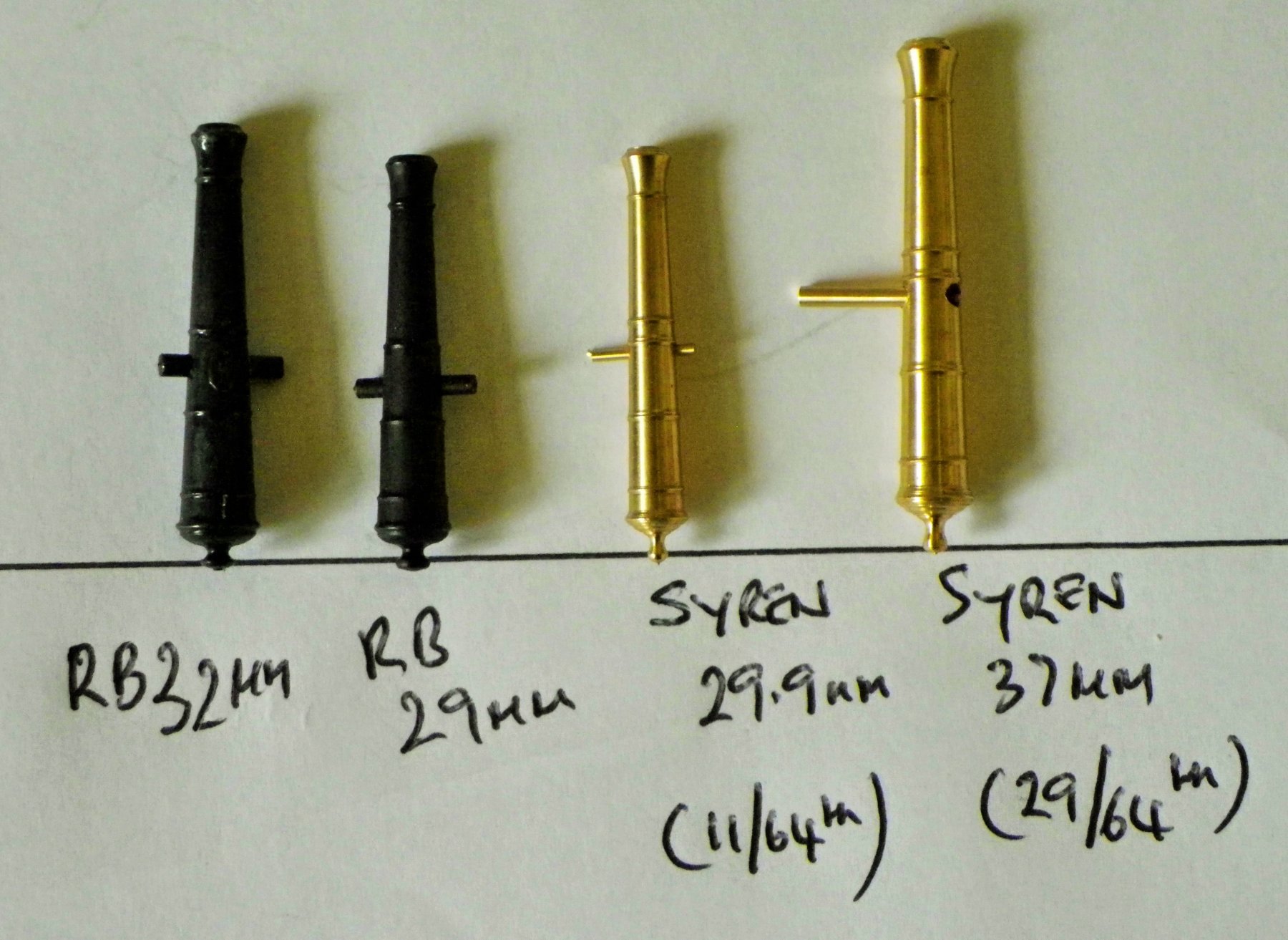
I looked at this during my build and I finally settled on RB32mm guns and the 15mm for the Swivels. However, the 29mm look fine as well on the carriage, and once they are all together along the broadside I don't think they will look undersized, I just preferred a slightly chunkier look. This is the comparison I made when deciding on my build, and as you can see the Syren version is finer still than the RB 29mm. B.E.

-
Hi Doug, the details are there, Page two, post 52- here's the link I think. Cheers, B.E.