HOLIDAY DONATION DRIVE - SUPPORT MSW - DO YOUR PART TO KEEP THIS GREAT FORUM GOING! (Only 20 donations so far - C'mon guys!)
×
Andre
-
Posts
152 -
Joined
-
Last visited
Content Type
Profiles
Forums
Gallery
Events
Everything posted by Andre
-
 Welcome back Jan! Good to see that your Vasa built is continueing! I see that you have white color for the horizontal parts of the ratlines. Most others (including myself) use dark color. Why the ligher color?
 -
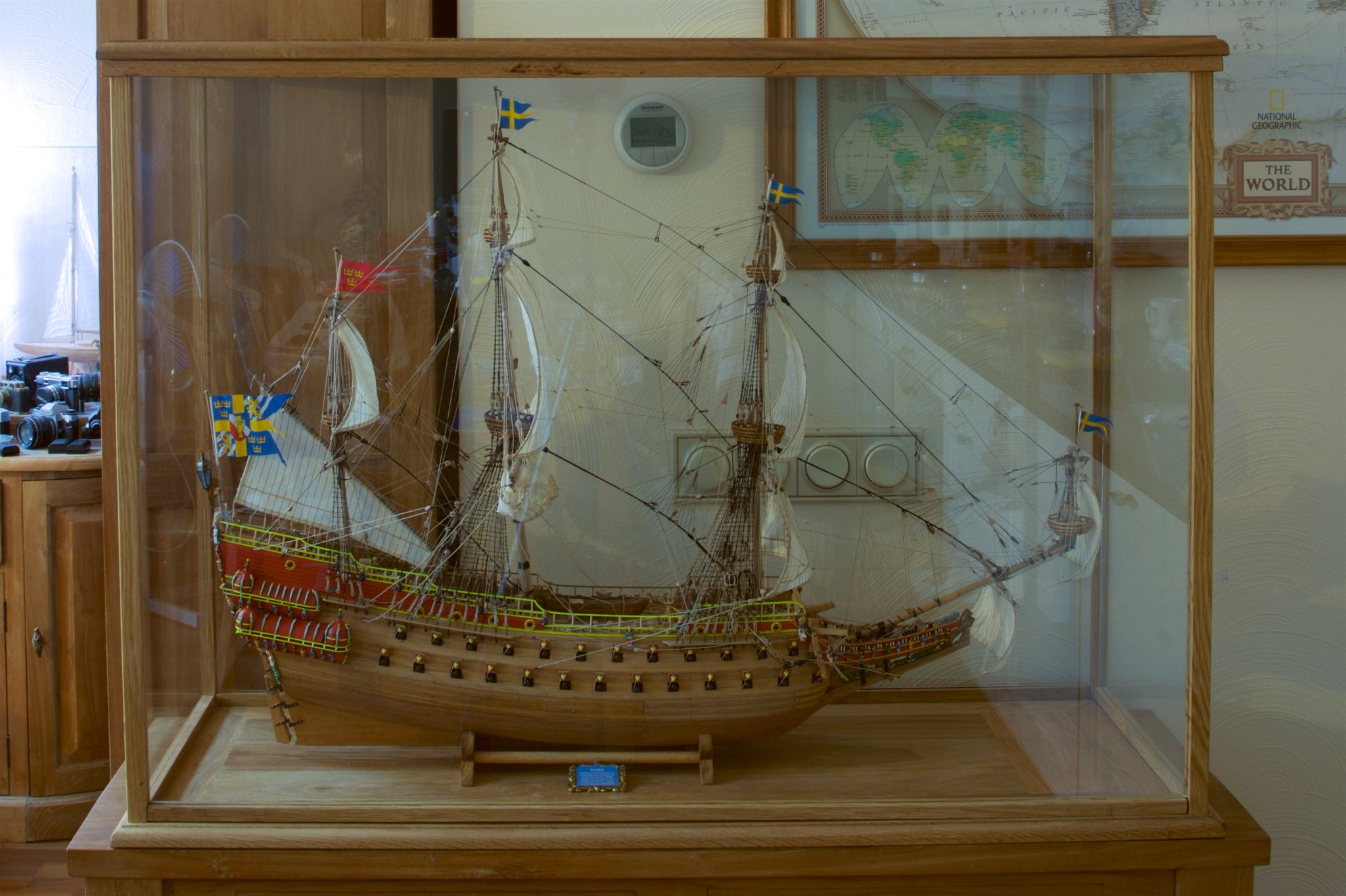
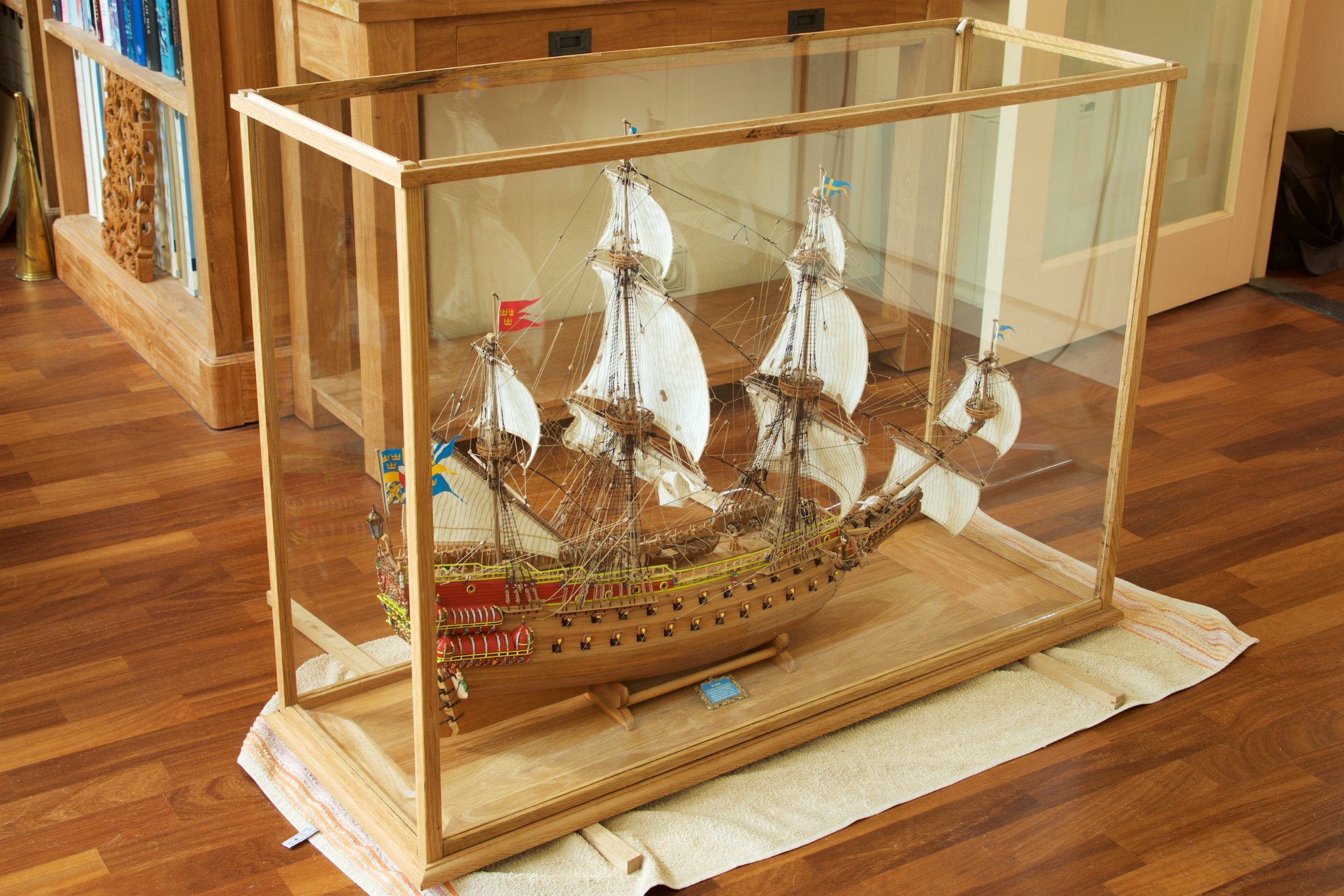
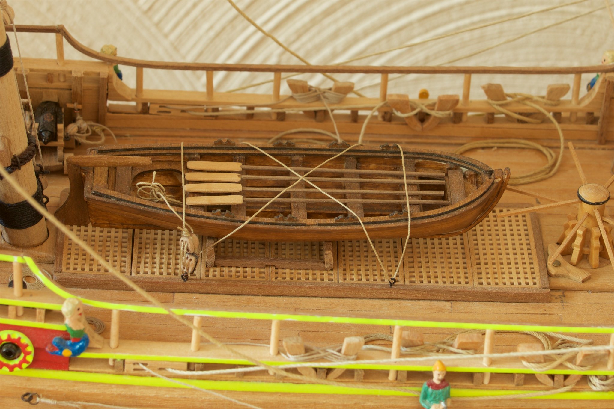
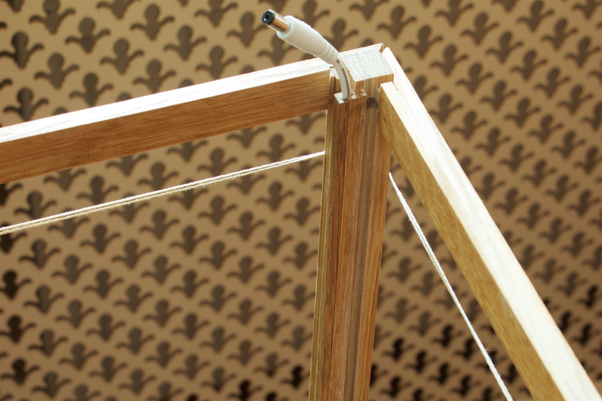
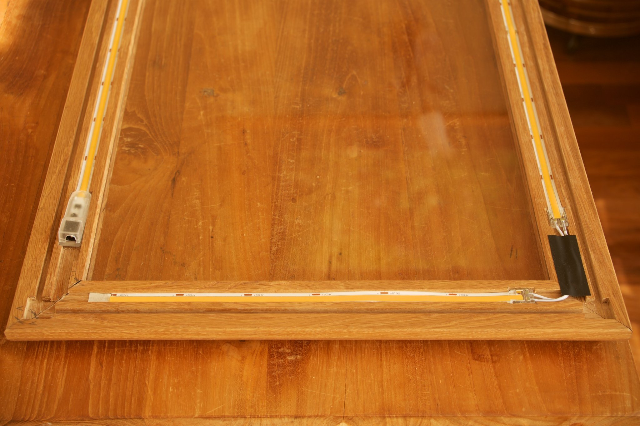
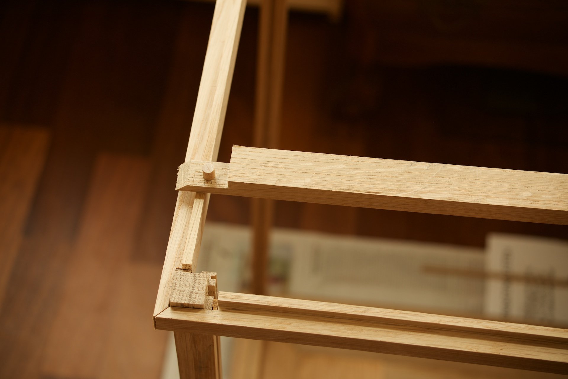
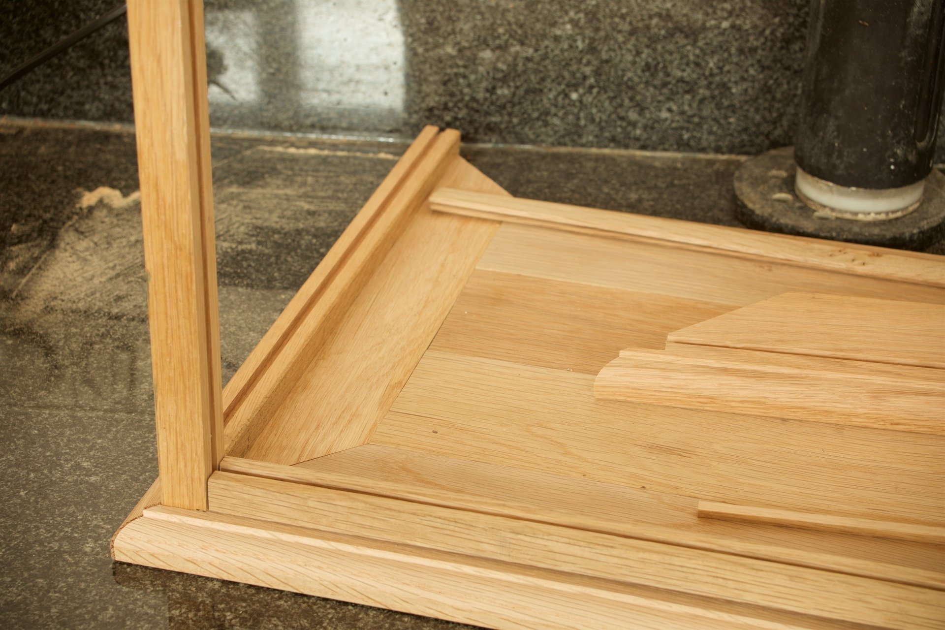
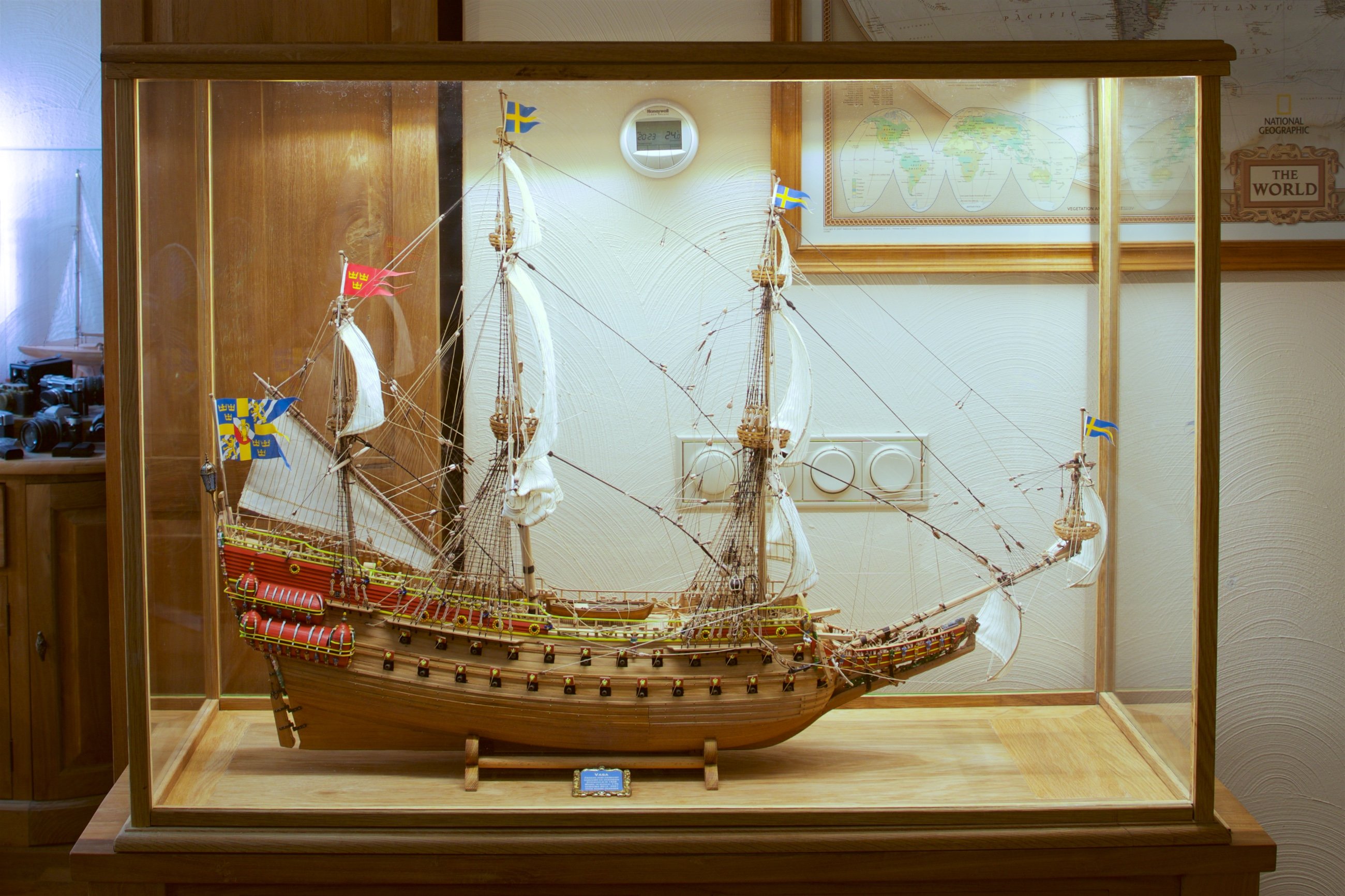
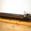
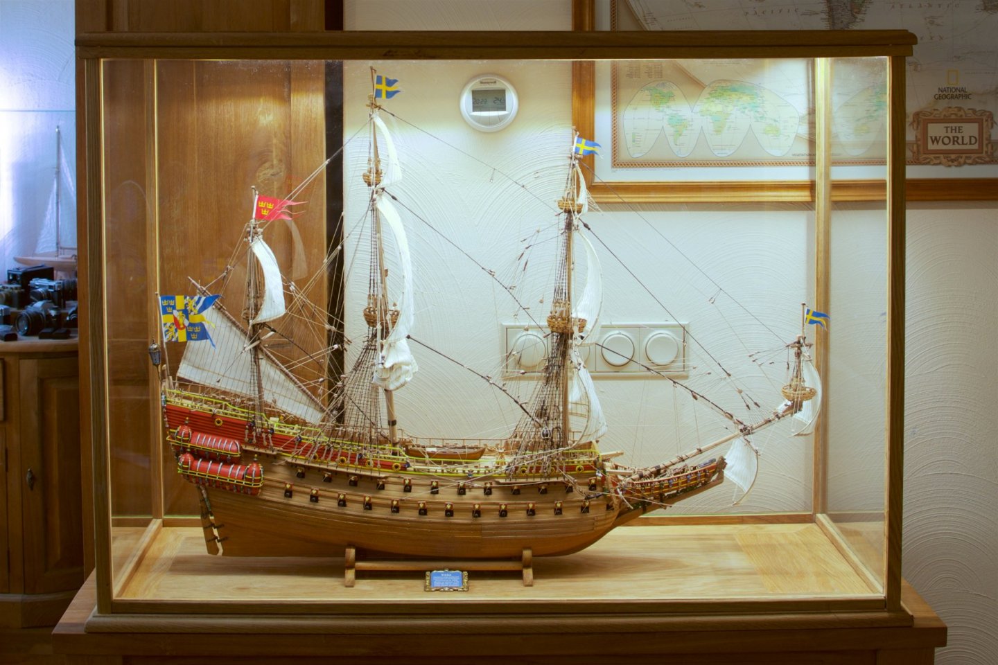
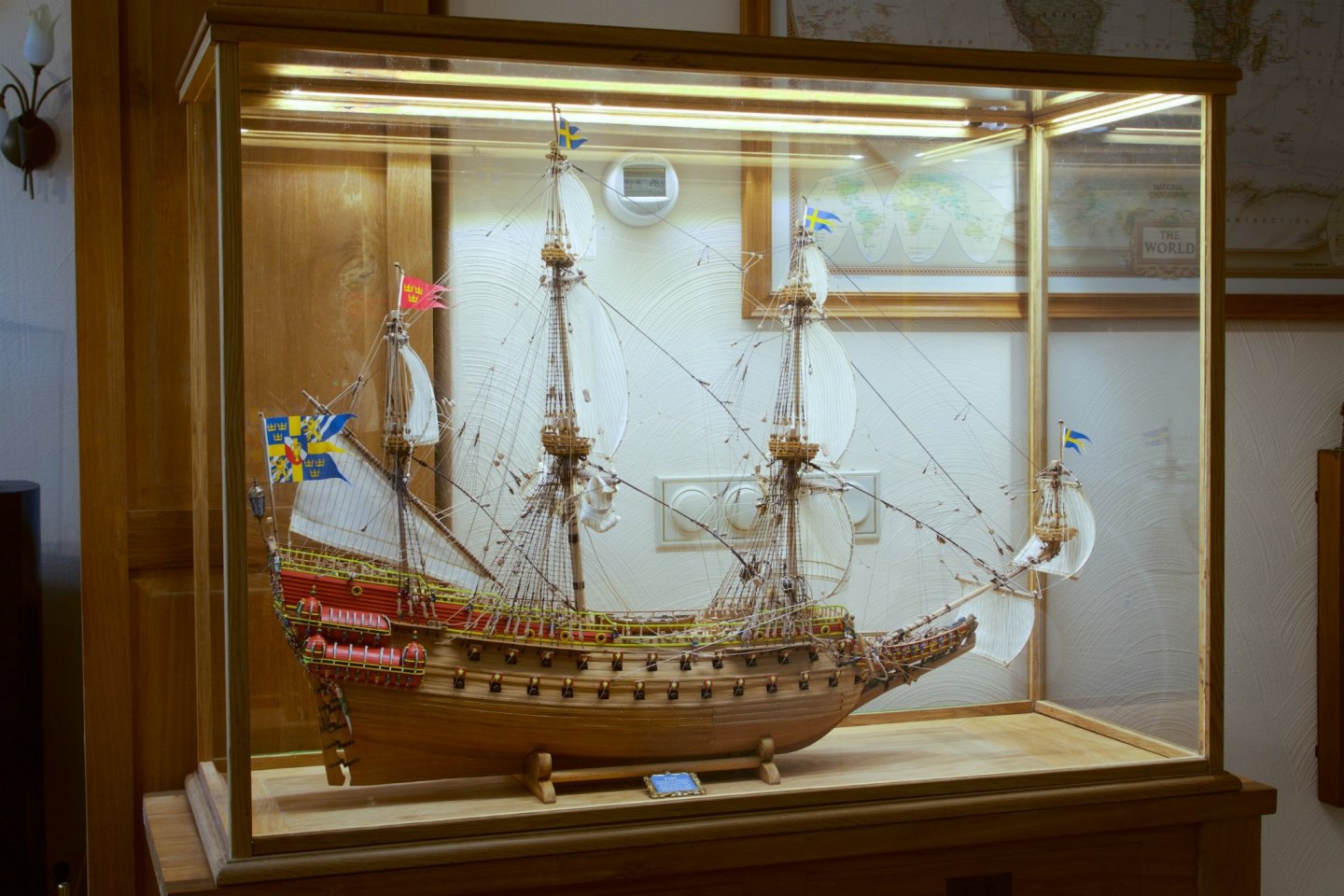
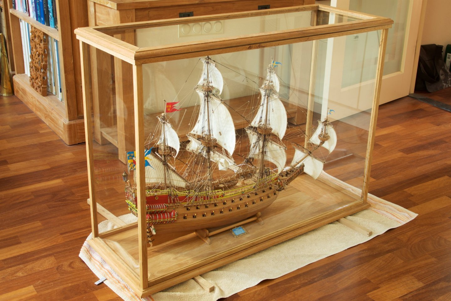
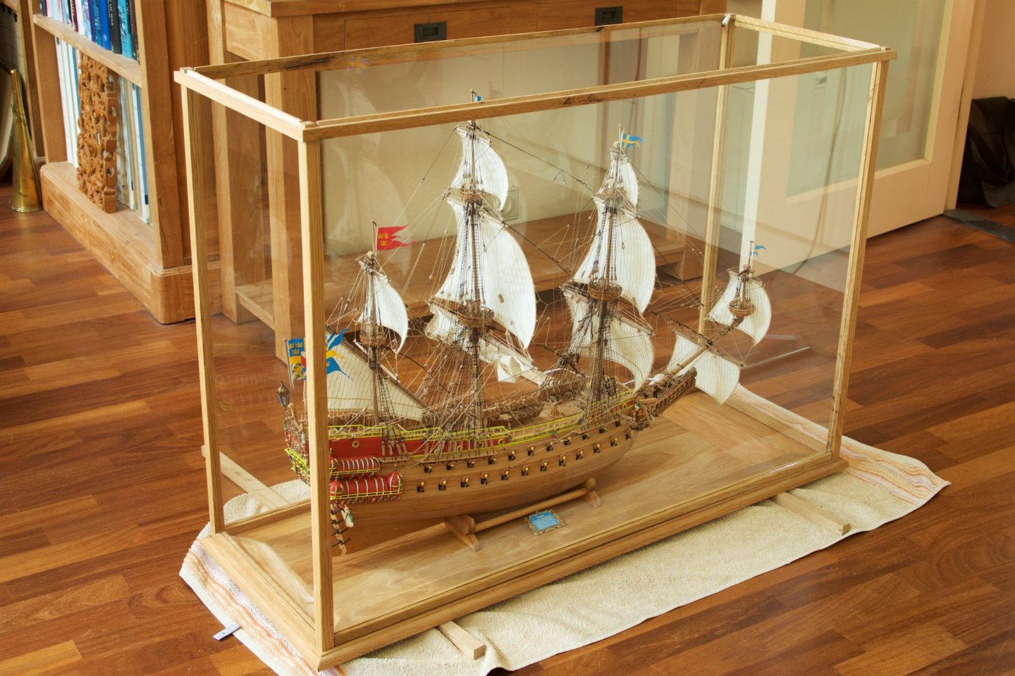
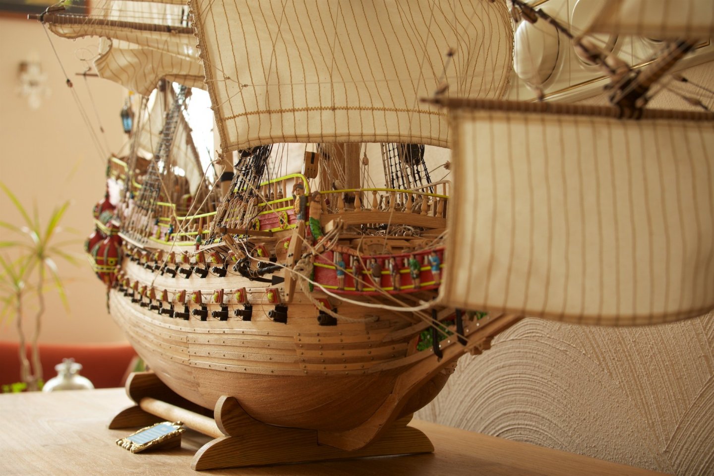
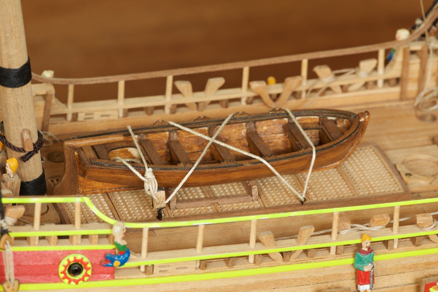
Before placing the model in the display case: one last detail: I made four oars for the life boat. The diameter of the length of the oars are 1 mm round nutwood. I had first made the wooden parts of the display case and then measured the sizes of the glass that I needed. The thickness of the glass of the lid is 4 mm, the thickness of the vertical glass windows is 5 mm. Without glass, the display case was kind of wobbly, but inserting the glass in the groves gave enormous stability to the complete set-up, even when the lid was not yet present. The lid of the case was made to house LED strips, for which the cable is housed in one of the vertical beams of the display case. The cable is hidden in a groove of the vertical beam, and a matching thin strip of wood, also with a groove, was then 'clicked' over the cable. So, this part is without glue. Most parts of the display case are without glue. Glued are the only the big base, the lid, the small pins on the top horizontal strips. To add stability, I also glued the horizontal top strips to the top of the vertical beams. To fix the stand of the model at the desired location on the base, I had made a small combined strip of wood that fits exactly under the stand, and glued this strip on the base. This allowed me to insert the ship into the display case from the small side. The Vasa in the display case is now COMPLETED. I am very happy with the results.


- 206 replies
-
- 15
-

-

-
I agree: the vintage one looks much better. It looks as if the mold (for casting the figure) was used too often and has lost some detail.
-
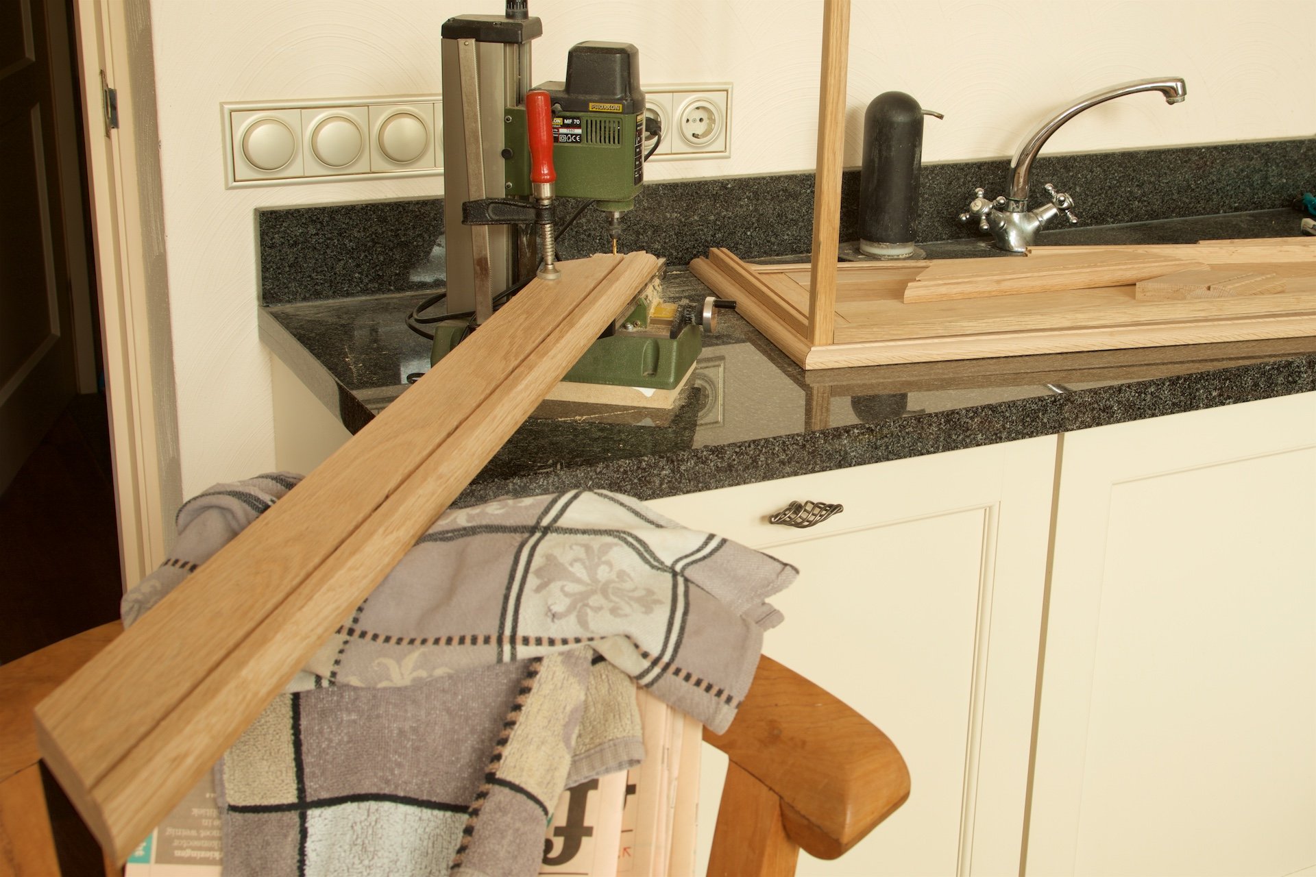
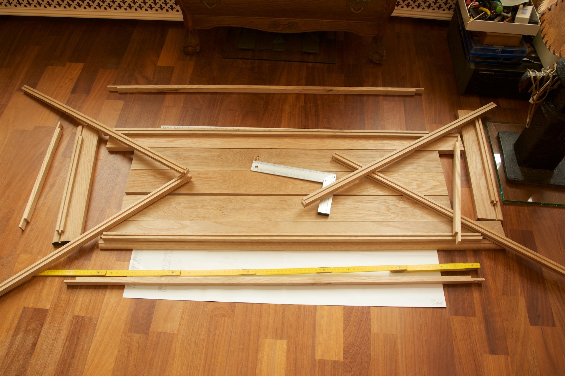
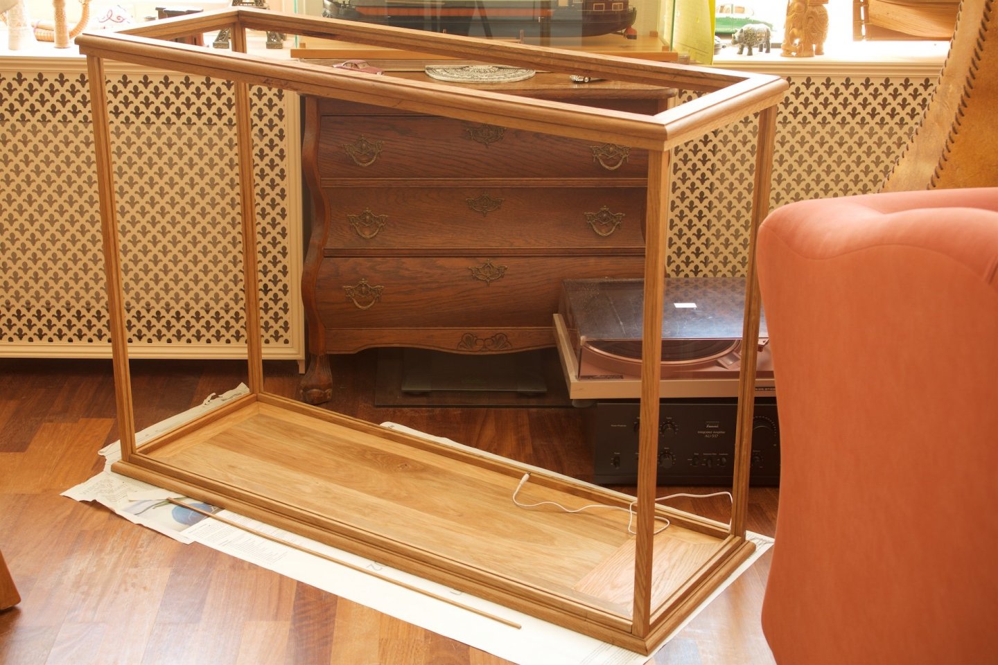
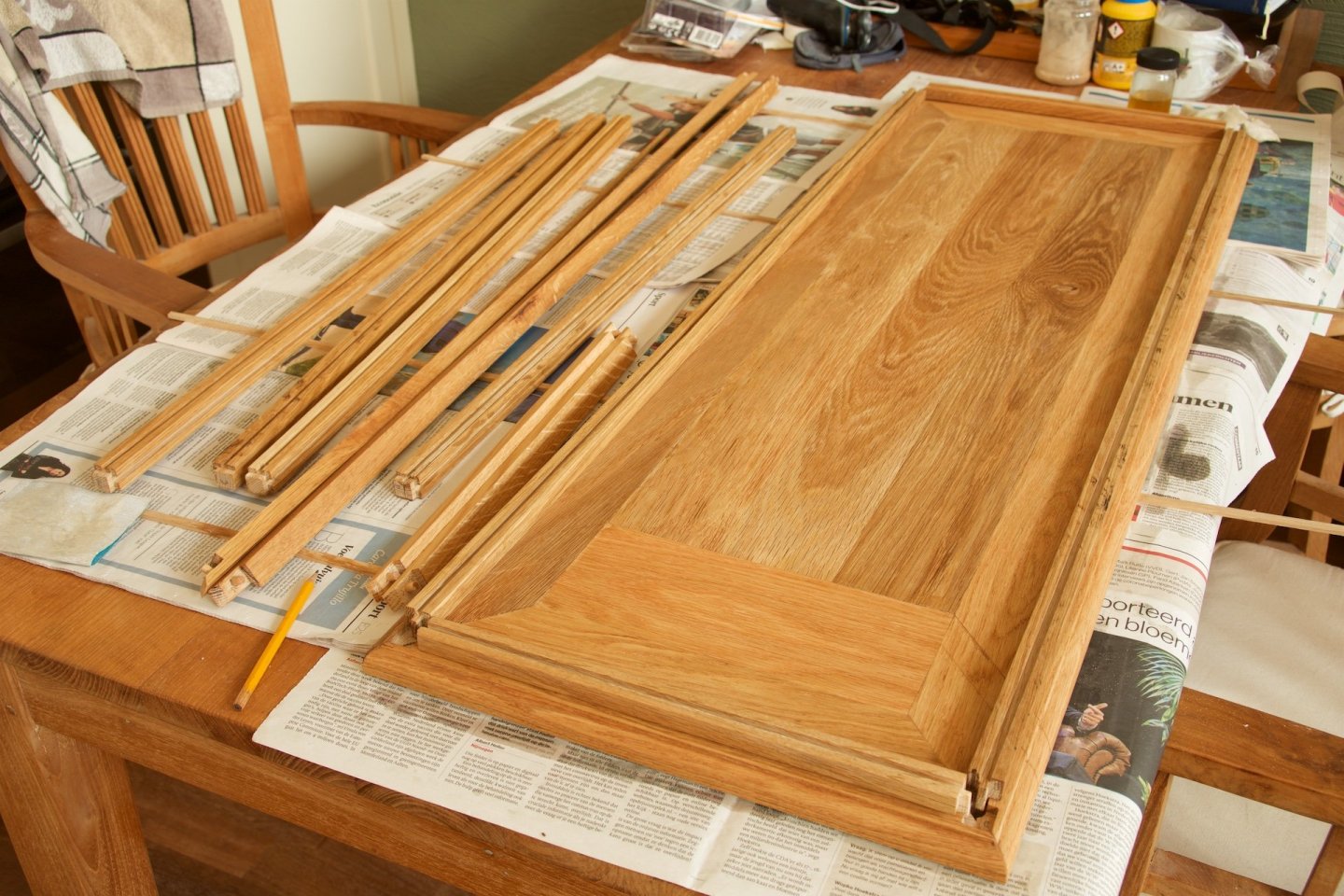
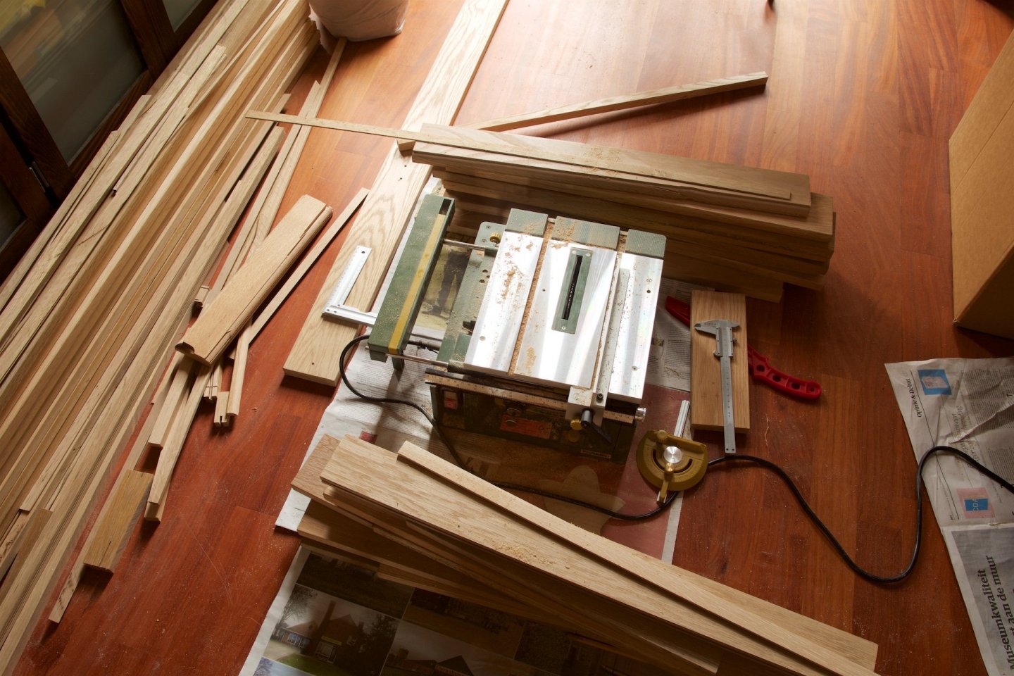
In the last weeks working on the display case. I had bought oak wooden planks, and I used mainly my table saw to make the planks and also to make the grooves in the various parts. I used my small milling machine to make the slots for the poles. My colleague helped me with the milling of the rounded curved planks, because I do not have such 'large scale' equipment. The display case is made such that it can stand on its own, without glueing, because of the (simple) mortise and tenon joints. The cover is prepared to house led strips. I used tung oil to treat the wood. Now it is ready, except for the glass that needs to go in it. I calculated that the weight of the 5 mm glass for such large areas (width of case is 110 cm and height is 80 cm and depth is 40 cm) of glass is really large. I guess about 40 kgs of glass...


-
Thank you for the nice comments! Jan, Indeed, I had noticed that your model (updates) had stopped for a long time. I will be looking forward to see your resumed updates.
-
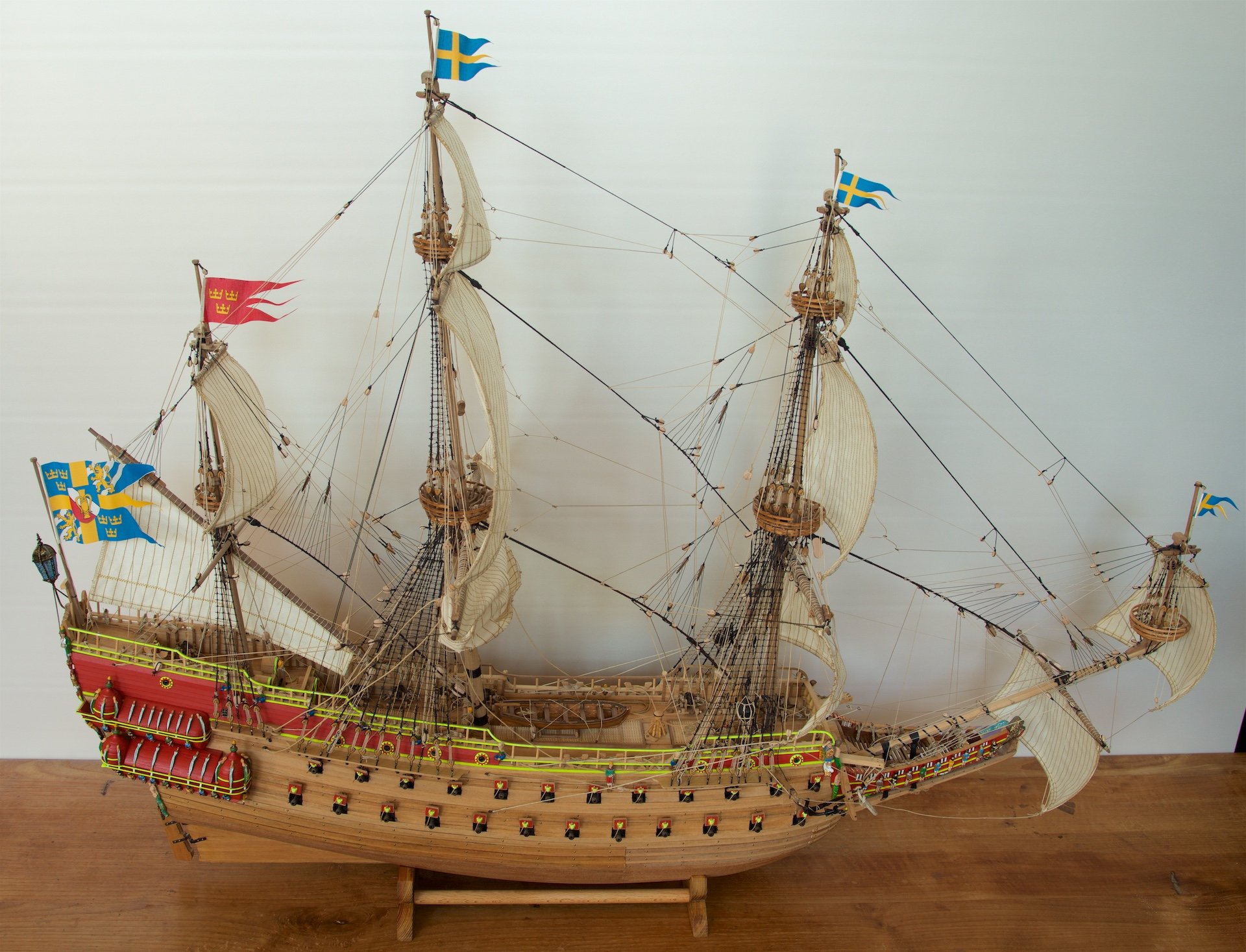
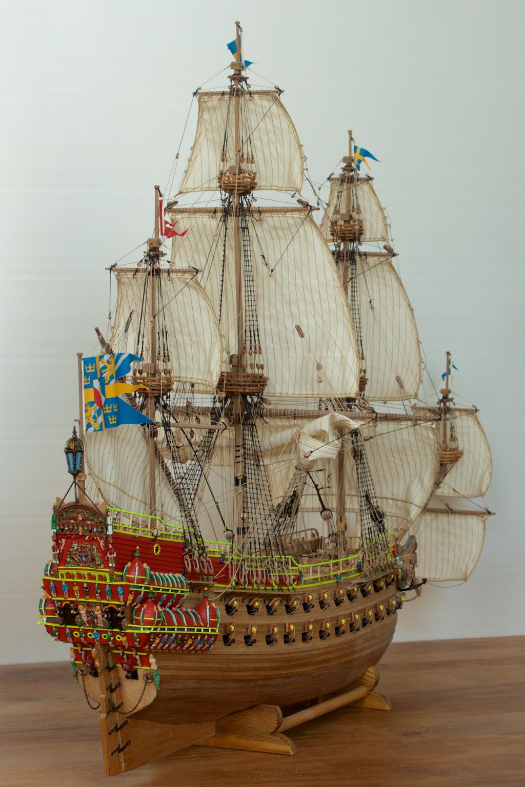
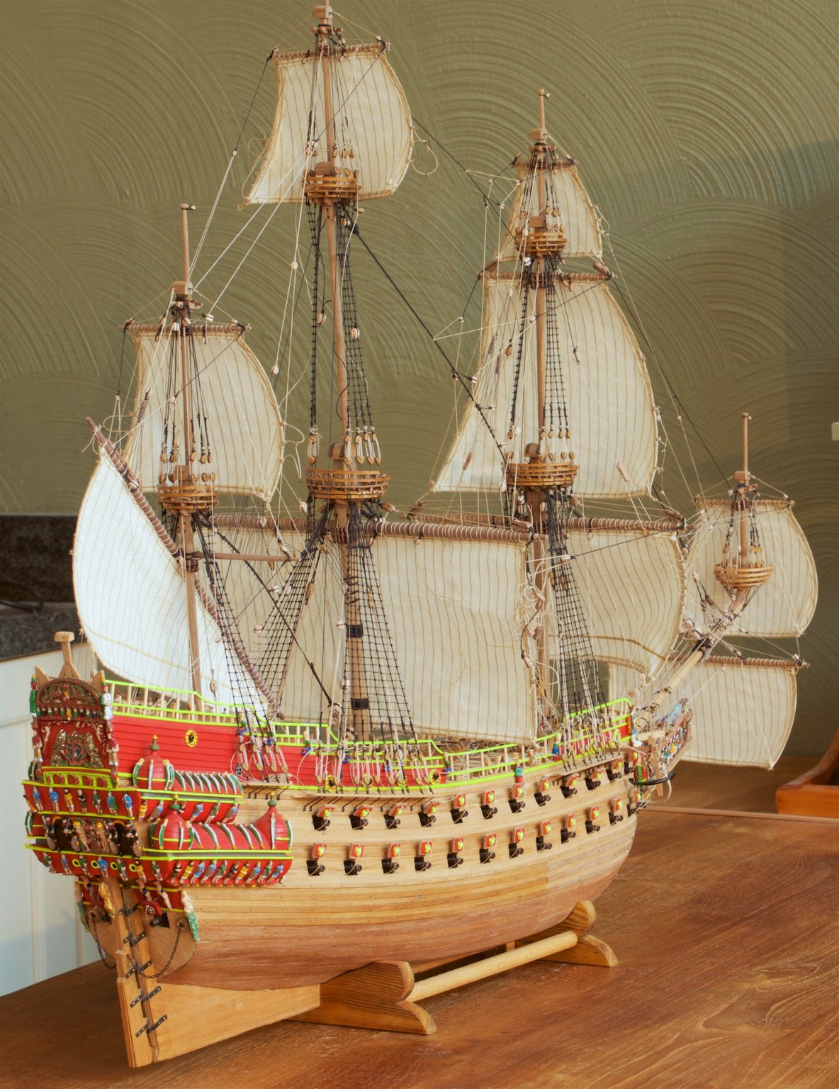
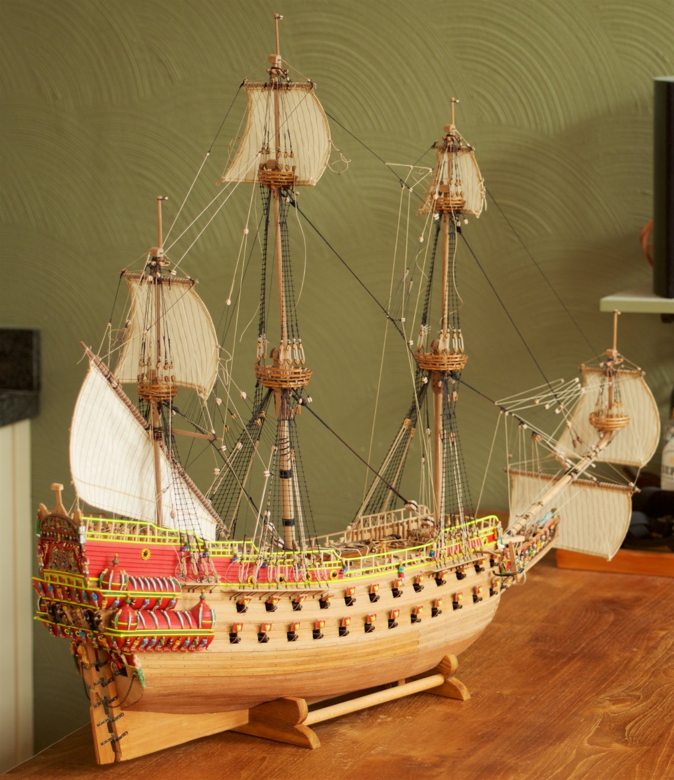
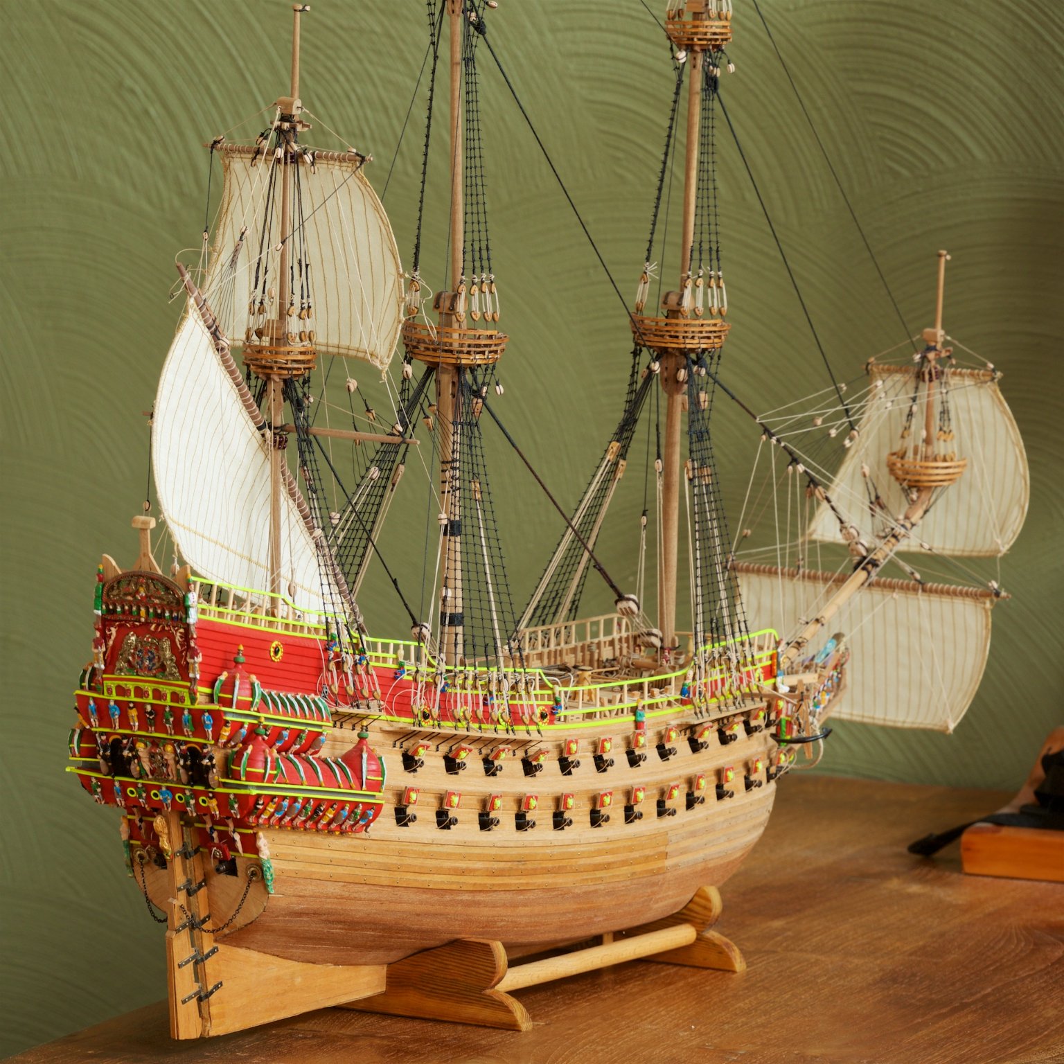
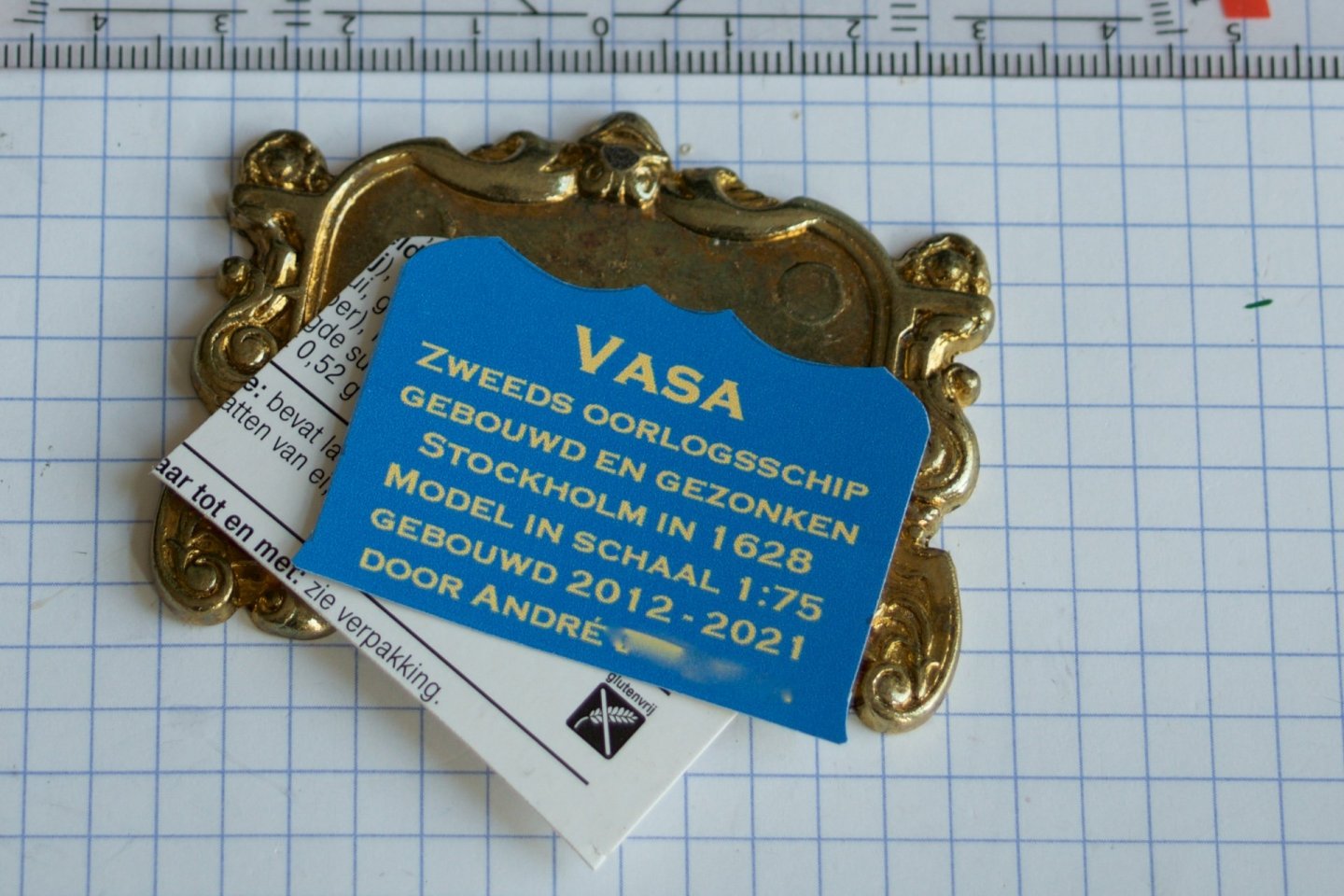
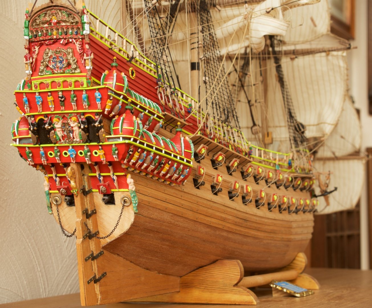
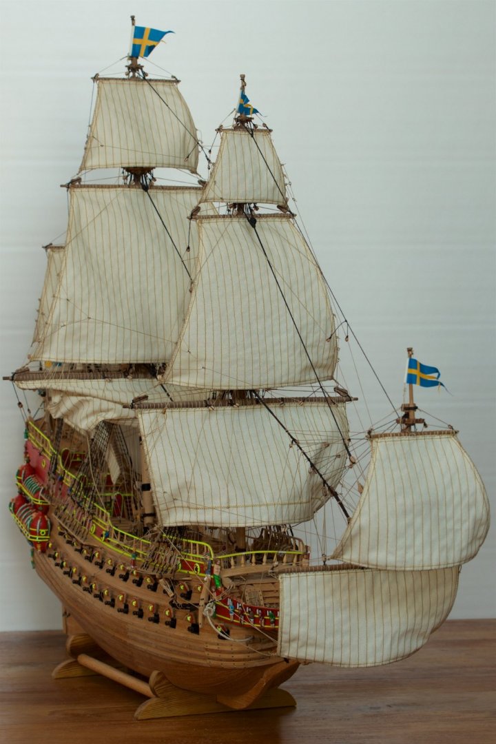
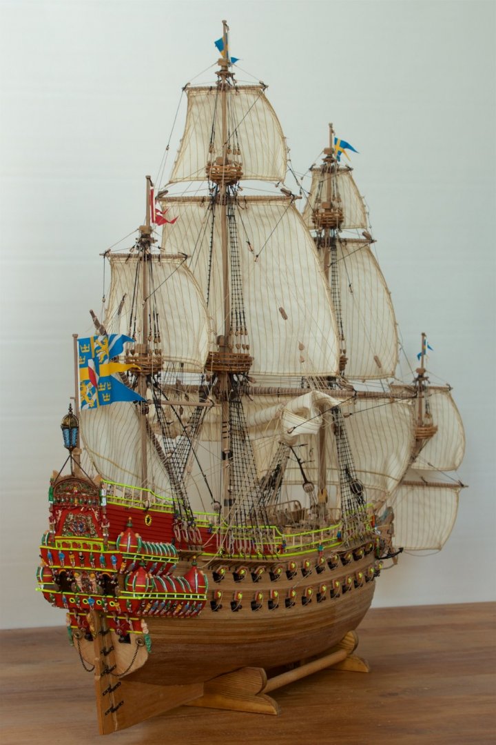
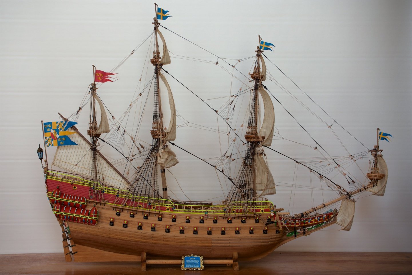
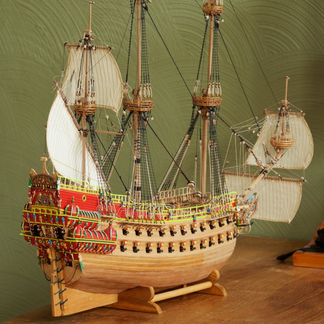
The last item of the model that I wanted to do was to make the name badge. I used the kit supplied shield and printed (at work) a sticker with the (translated from Dutch) text "Vasa Swedish ship of war, built and sunk in Stockholm 1628. Model in scale 1:75, built 2012-2021, by <me>". The sticker was cut to fit into the shield. I have added some photos of my now completed VASA: The next big thing for me is building a display case. I have seen a very nice one here on MSW and will use it as guideline: The display case made by Shipshaper for his Emma C Berry


- 206 replies
-
- 15
-
-

-
-
Hi Frank, Thanks. I had read that in your log. Luckily, my flags were the same color on both sides.
-
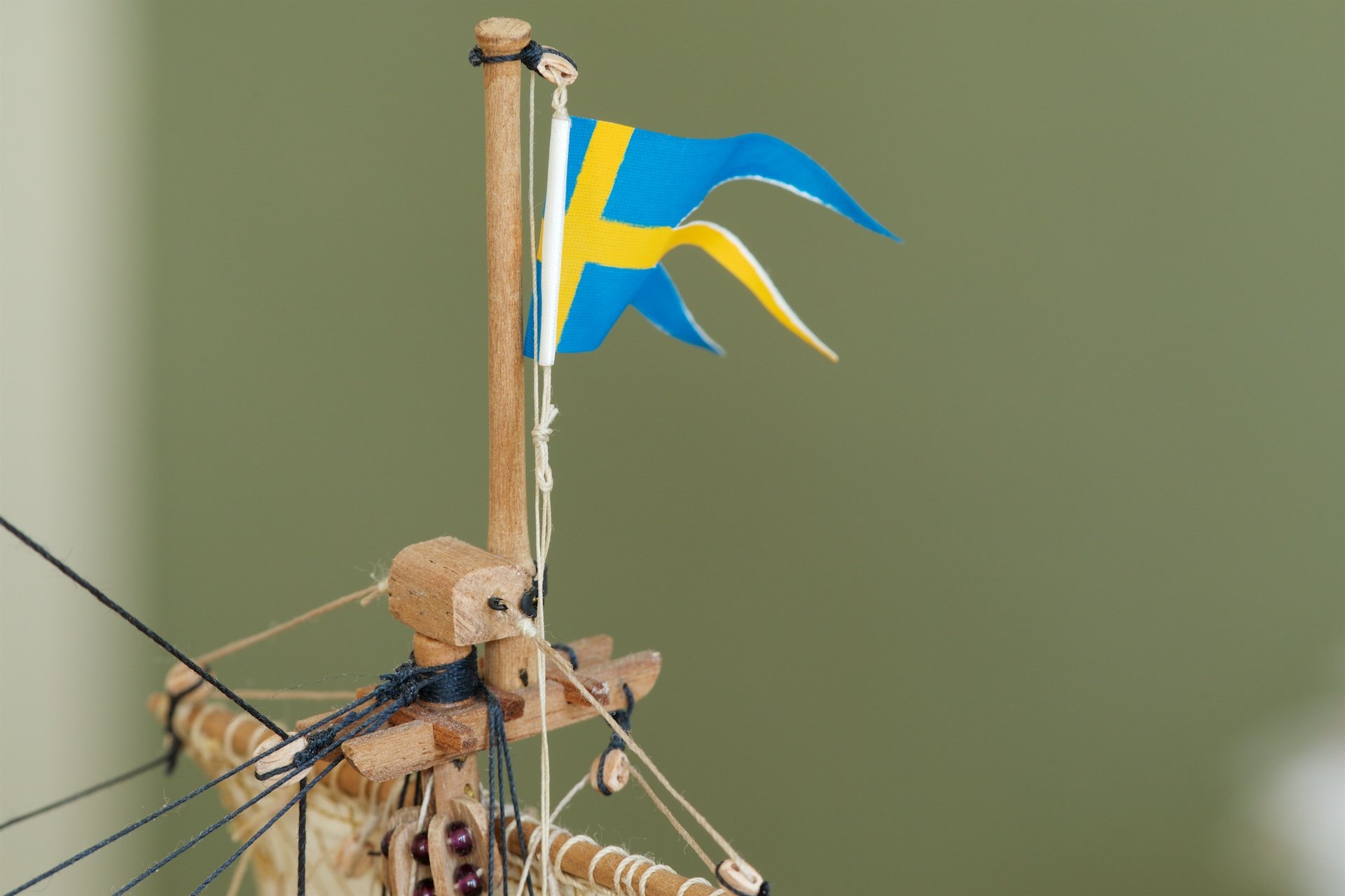
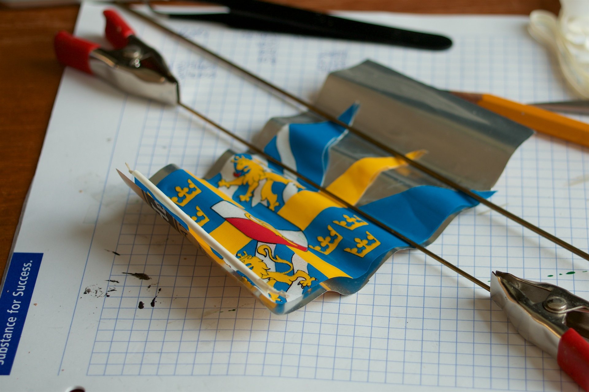
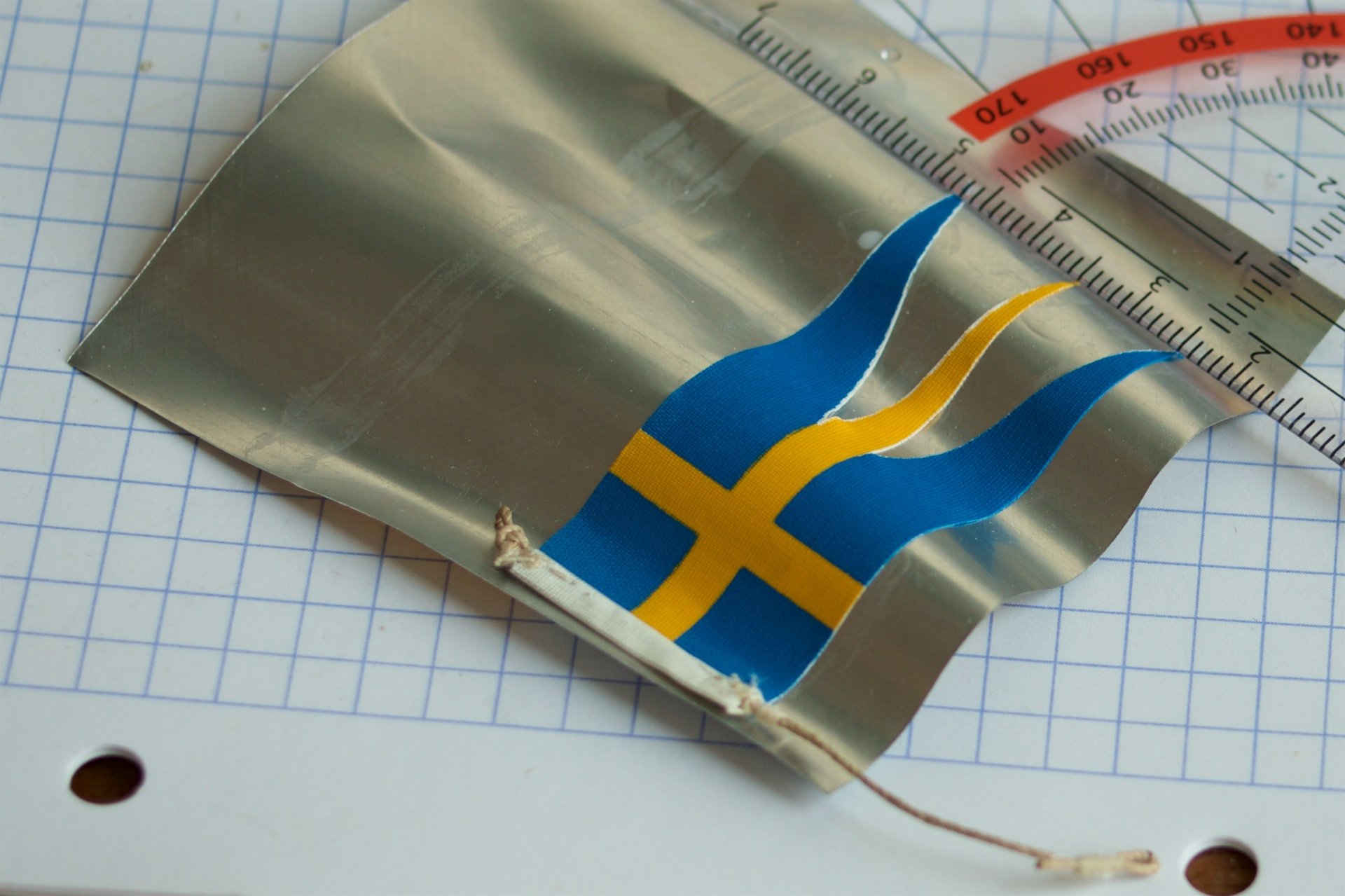
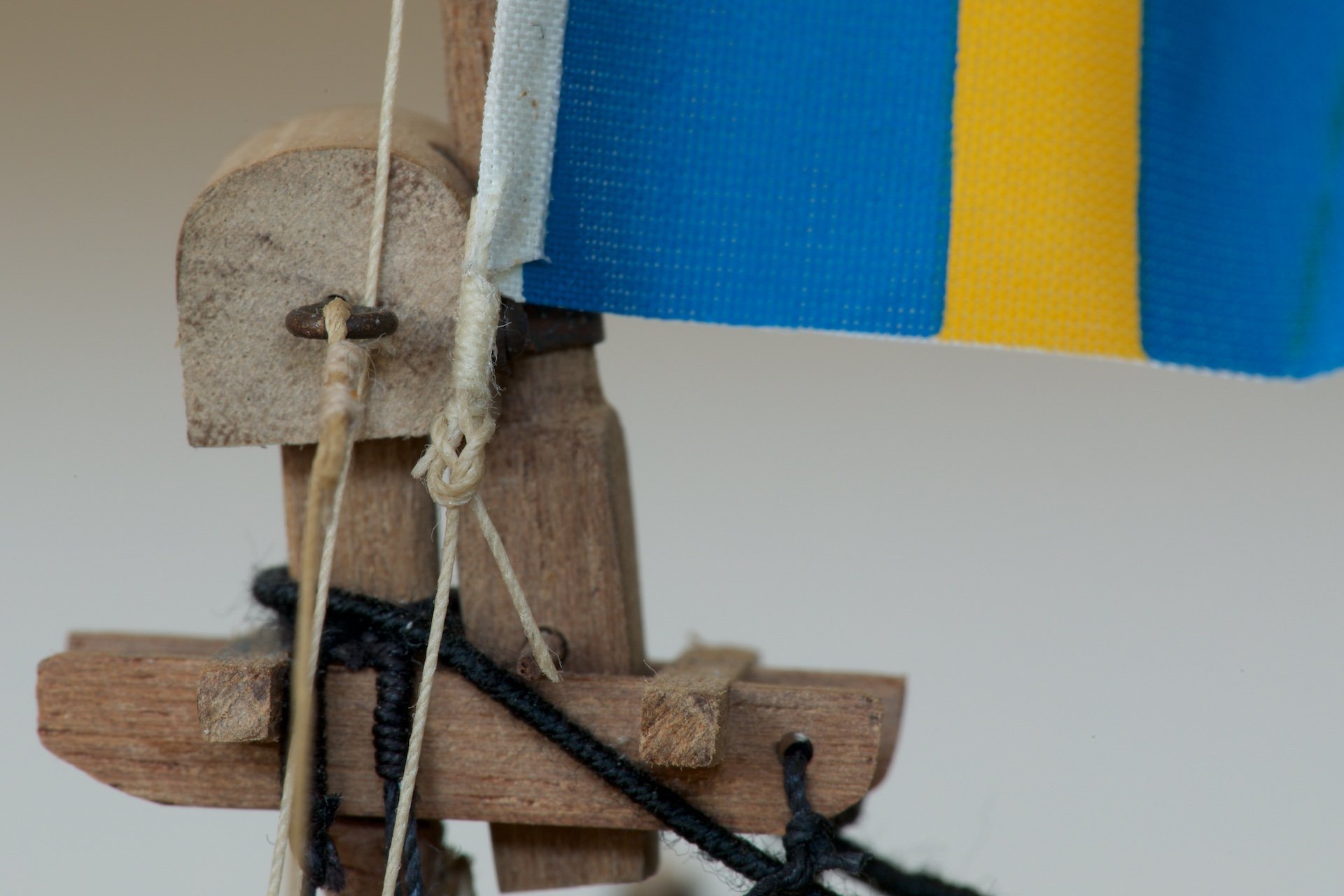
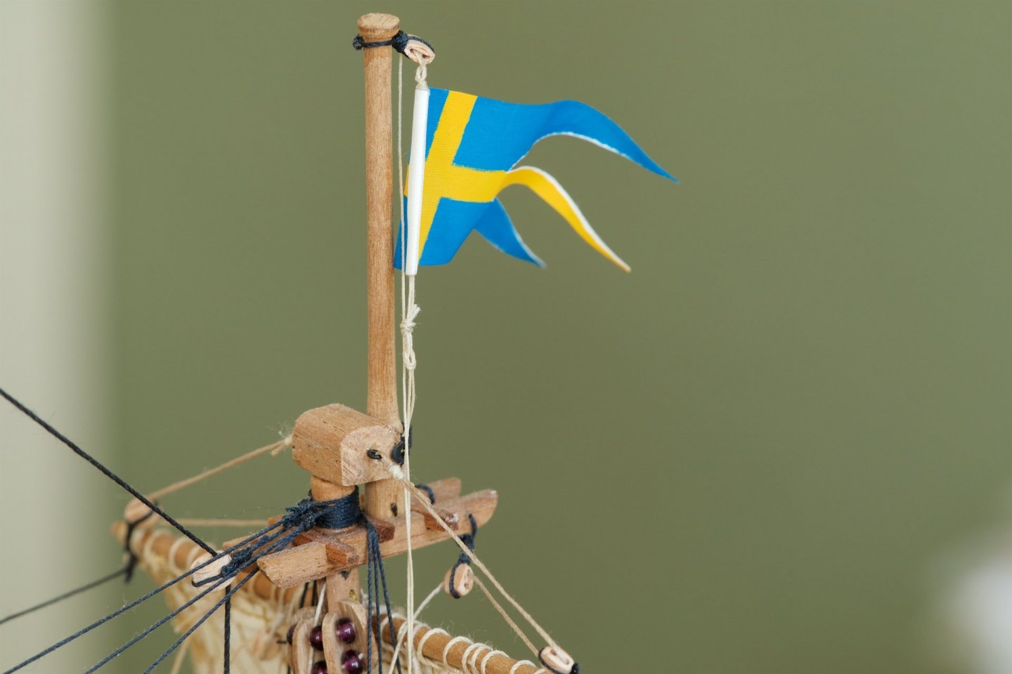
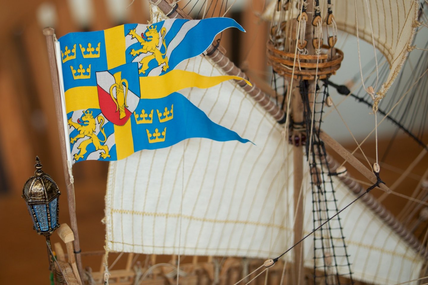
I made and installed the flags, which were supplied in the kit. I have shaped them with via the ' tin can' method, using diluted wood glue to fixate the shape of the flags. This worked quite well. The flags were made with small rope loops, and I connected one long line/rope that ran circular: from the top of the flag, through the block and then to the bottom of the flag, using the same 'knot' as for the sheet lines. This left thus a double rope to tye to the belaying pin. To make it easier to attach these double lines to the belaying pin, I had glued the two lines together. The big flag at the stern flagpole was not done using a seperate block at the top of the flagpole, but I had made the top of the flagpole to function as a block, by drilling two small holes in the top. The line runs through this. I did so, because the (much smaller) flagpole of my fathers ship (see one of my completed builts) also had the block inside the top and not separately.


-
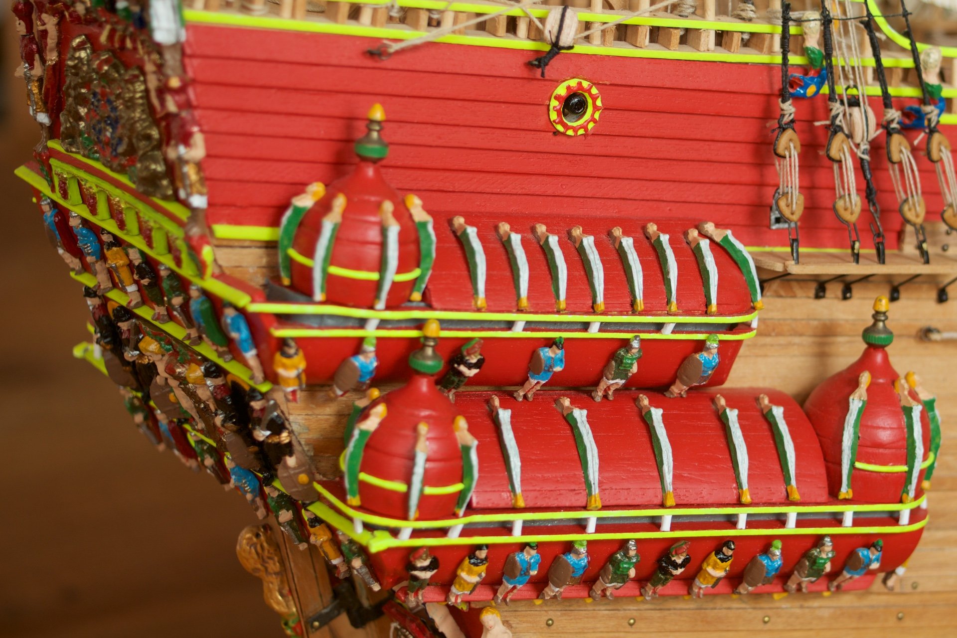
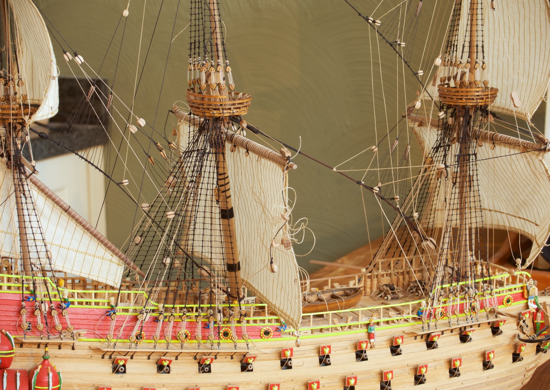
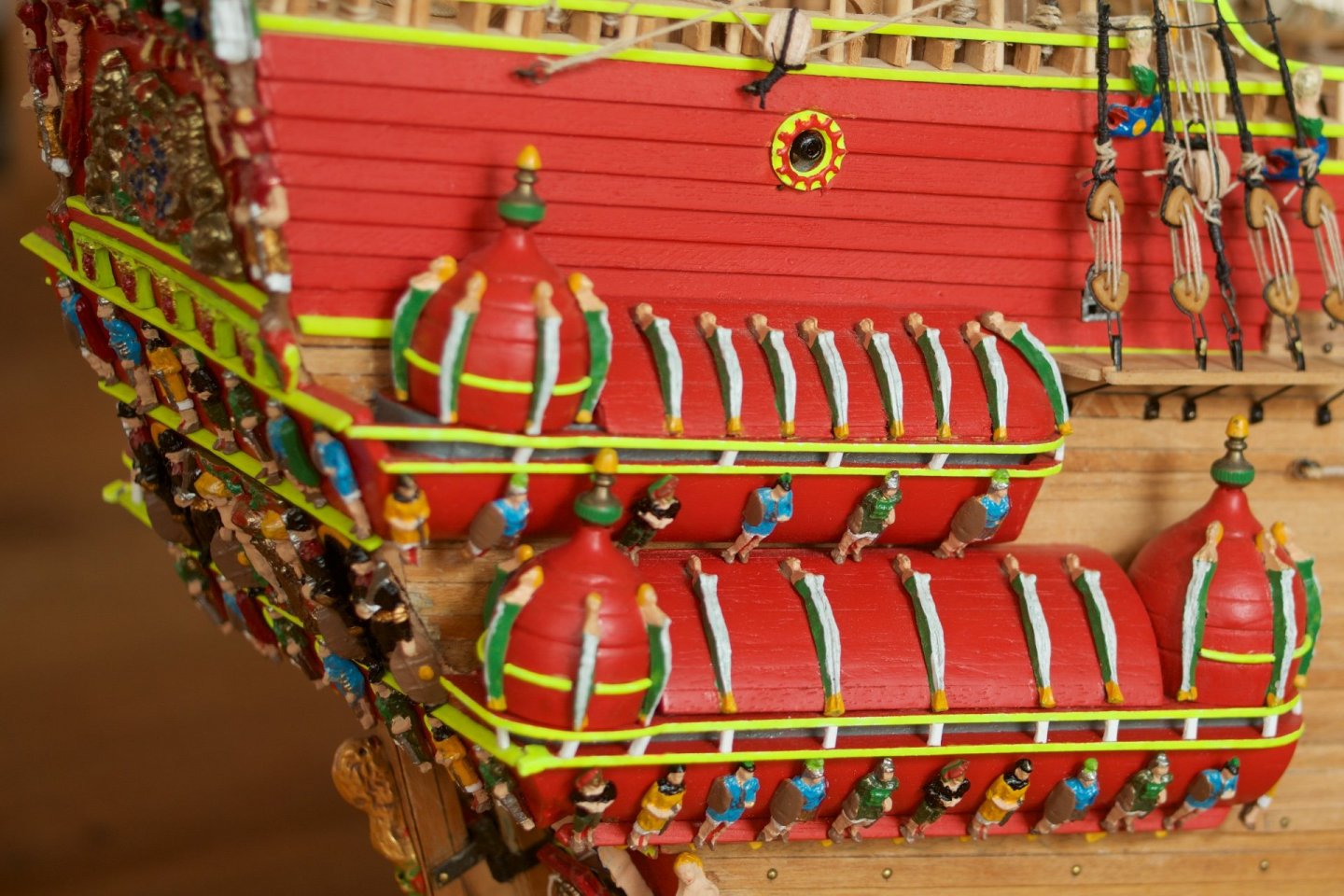
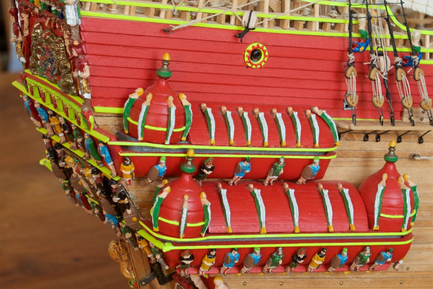
The galleries were already some years ago made by me, but they were not yet fully complete. I had earlier replaced the supplied metal parts by simple wooden strips, that I had painted yellow. And between them, I had left empty space. Now, I have added some small wooden pillars, which I had painted white. The size was 2 by 1.5 mm. I have placed them in line with some of the decorative figures on the roofs. Picture before and after (at almost the same camera angle..)
-
Micheal, Thank you for your comments. Of course, I had looked carefully at your example and solutions. I did not know that no lantern was found of the real Vasa. As it is thus unknown how a lantern would have looked (if added after its maiden voyage), all interpretations may be valid.
-
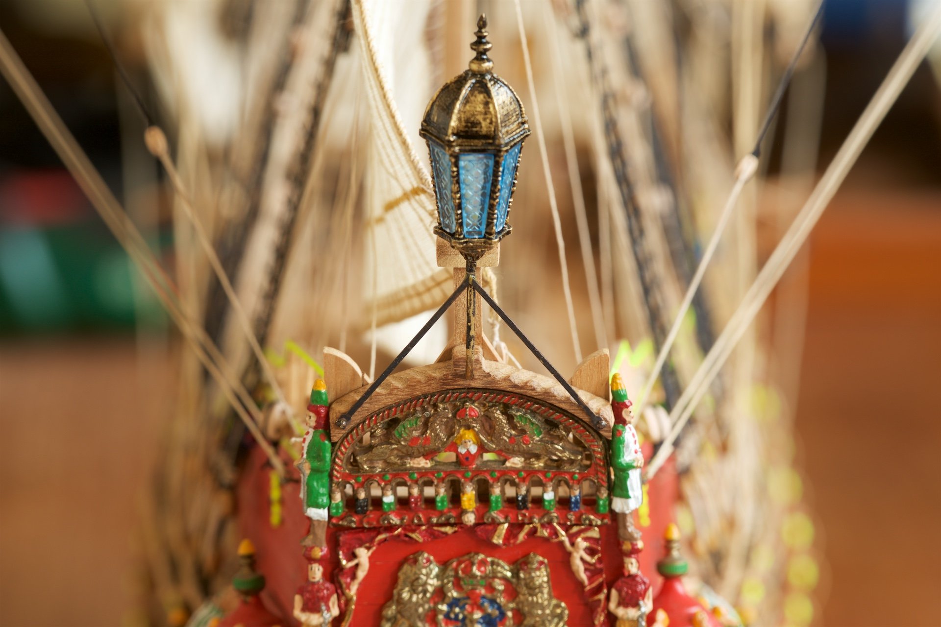
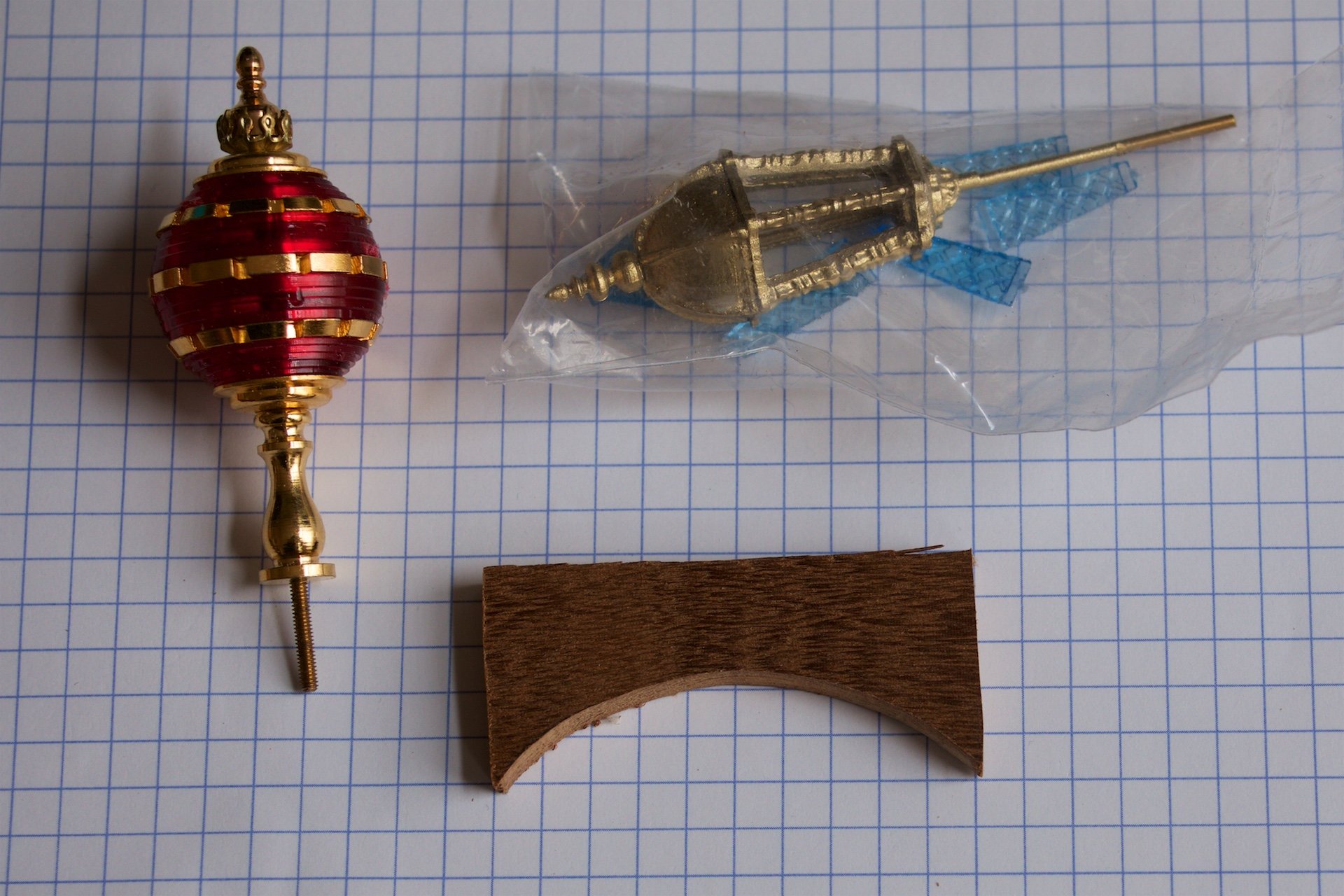
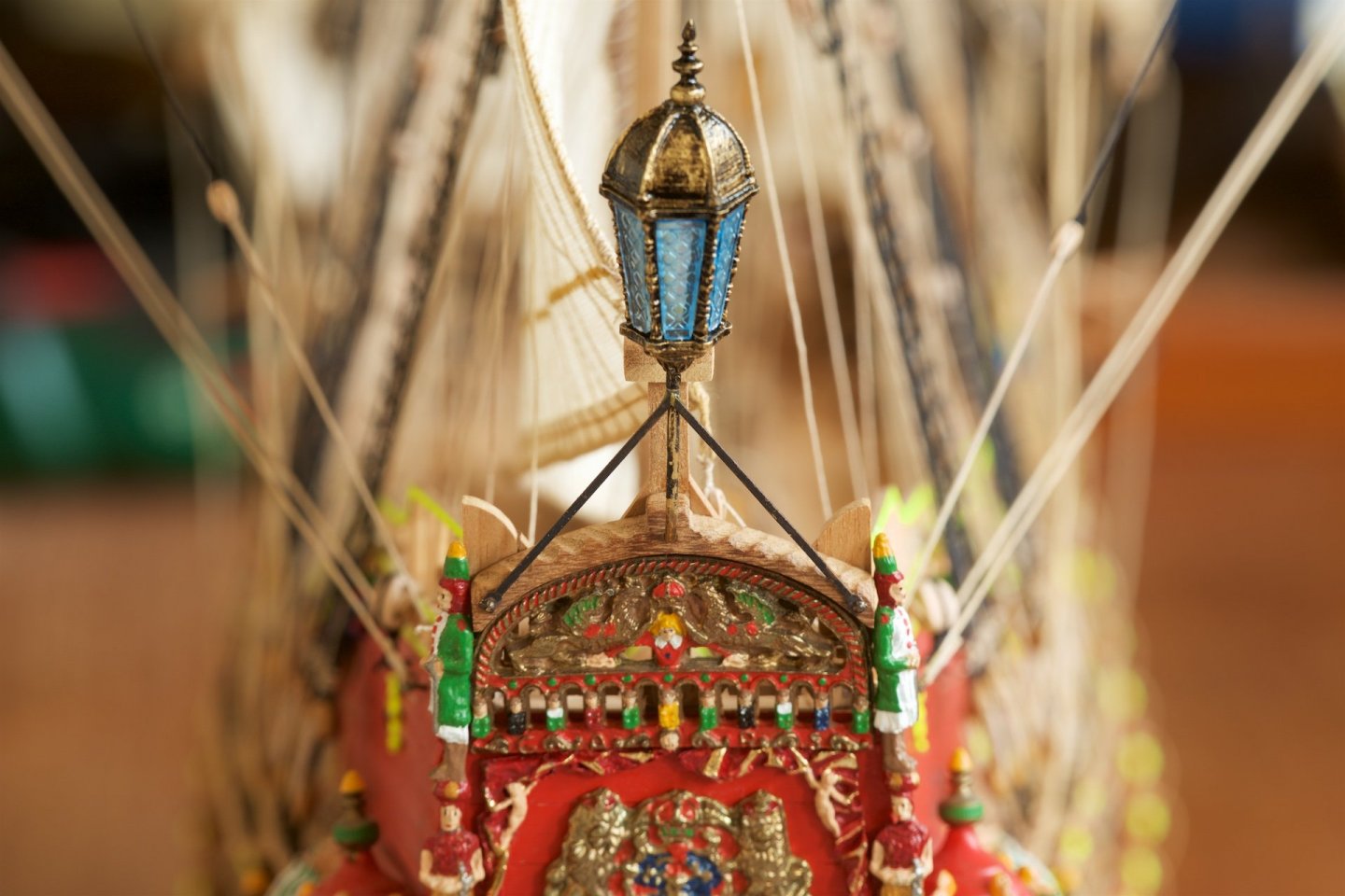
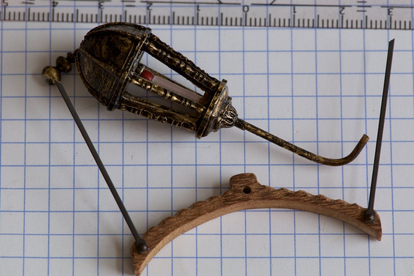
I have made and installed the lantern at the stern. As many Vasa builders on this forum, I have chosen not to use the kit-supplied circular lantern (first picture), even though the Zu Mondfeld book does have it included as Swedish example. It turned out that I had another lantern in stock, but I do not remember how I obtained this, probably in a combined purchase. This lantern was more traditional shaped. I did insert a candle-like shape, but this is not good visible anymore once the plastic windows were placed.. I found the color of the lantern too shiny, so I painted it with black paint, and then padding some of it away. This because I do not have a 'wash'. The lantern was attached to wooden piece that I made to fit the top of the existing stern ornaments. The orginal Vasa in the museum has here some snakes sculpted in the wood, but I am not able to do this. Therefore, I made some groves in it, to give this wooden piece 'less weight' appearance.

-
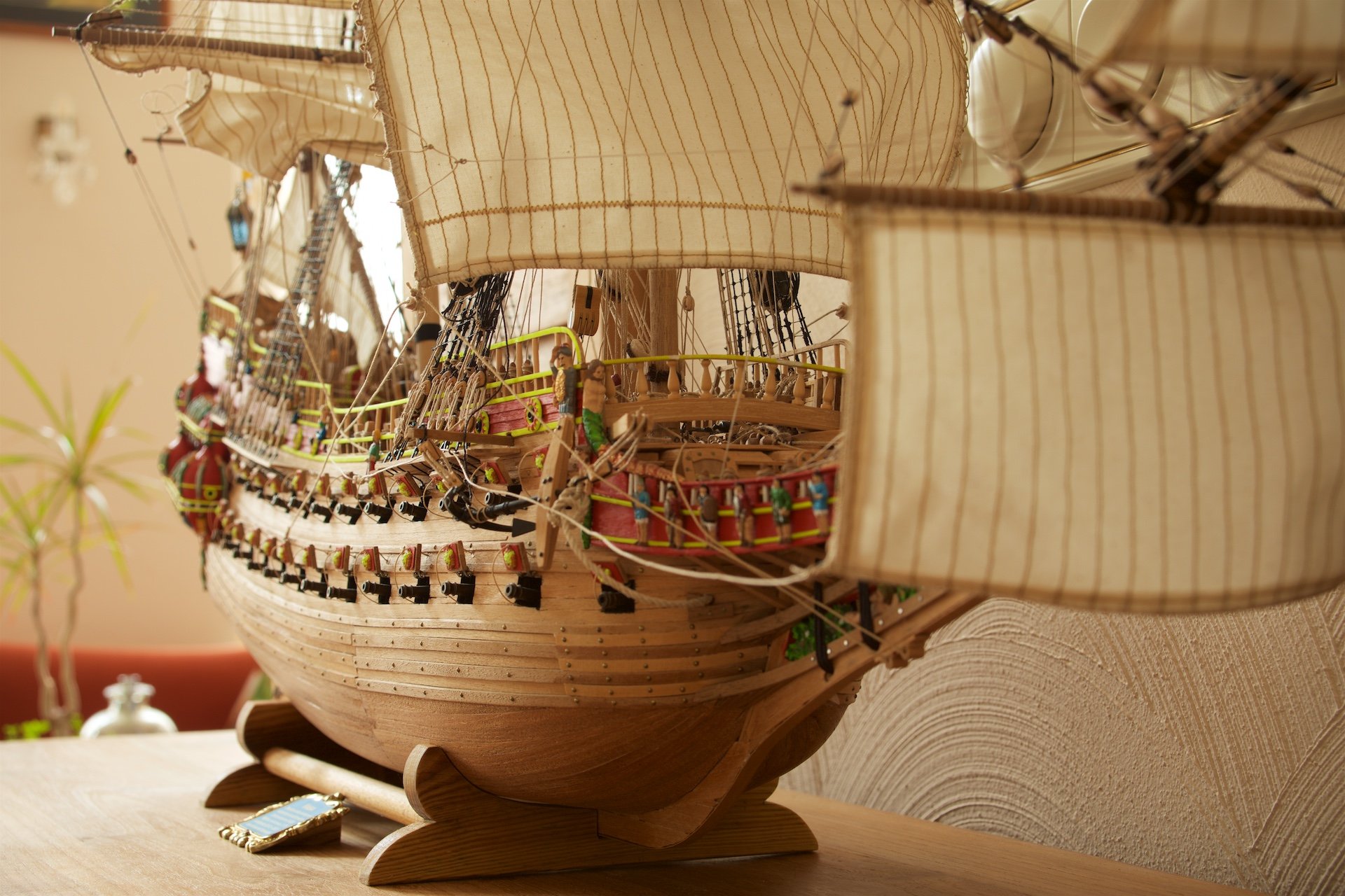
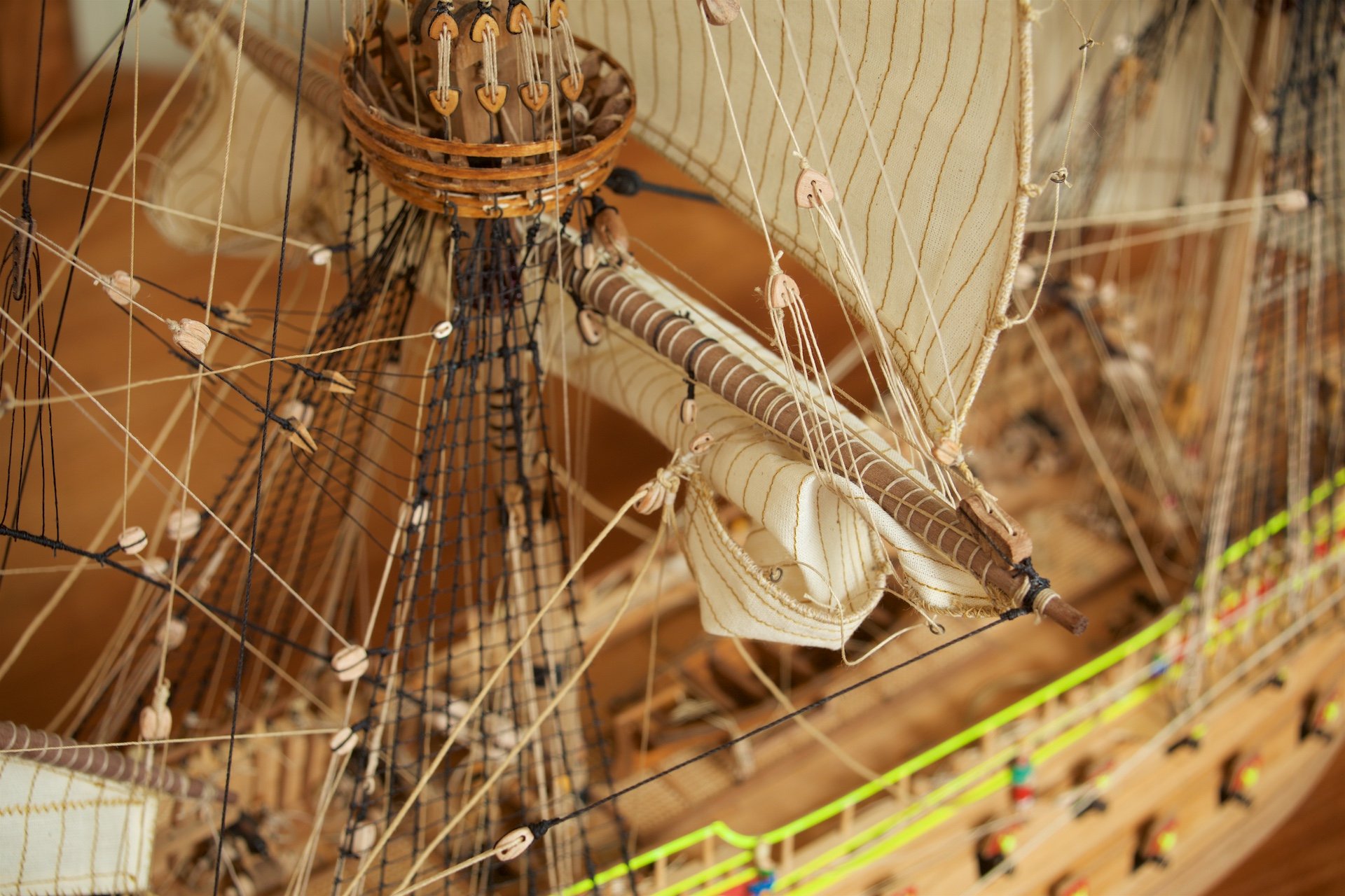
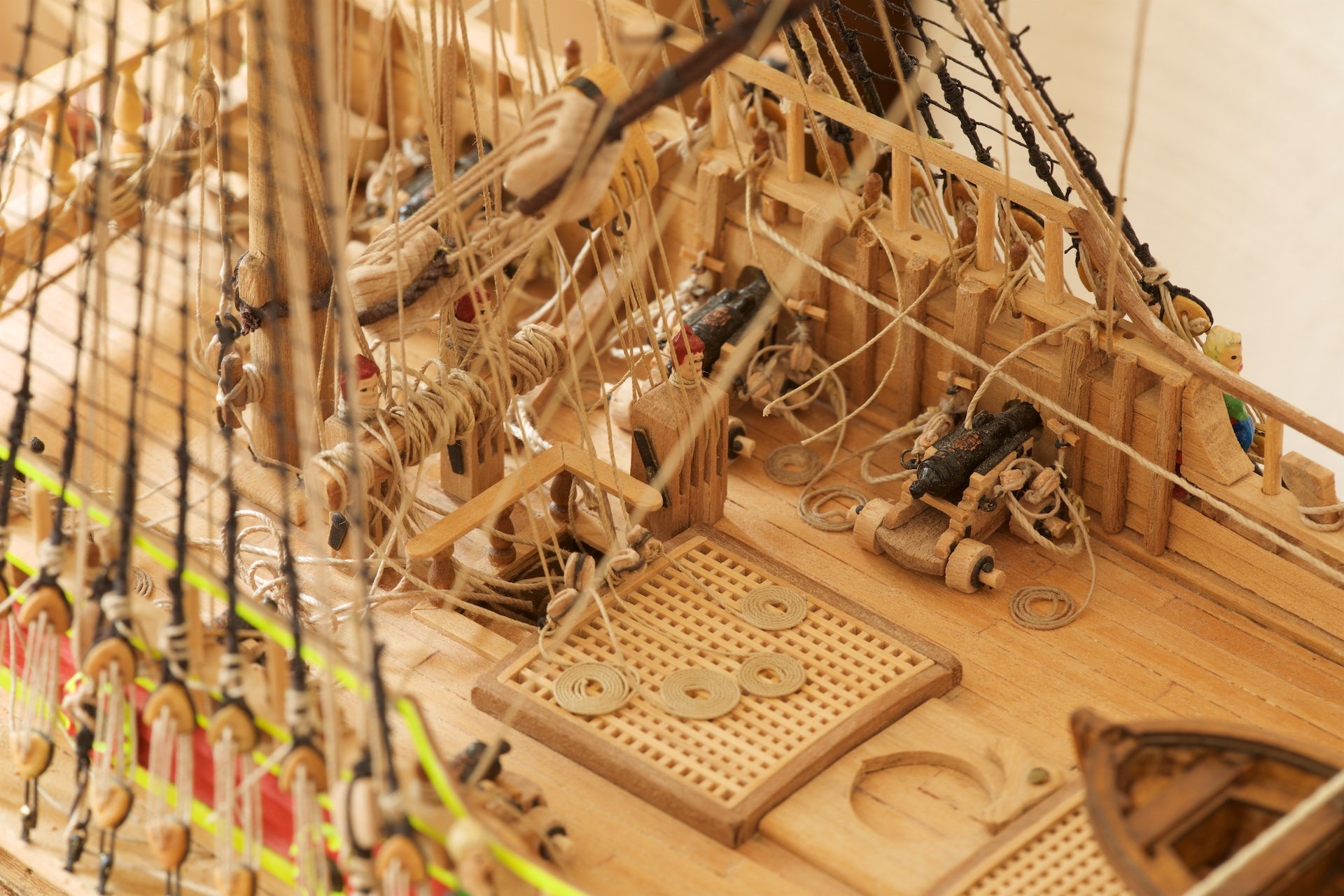
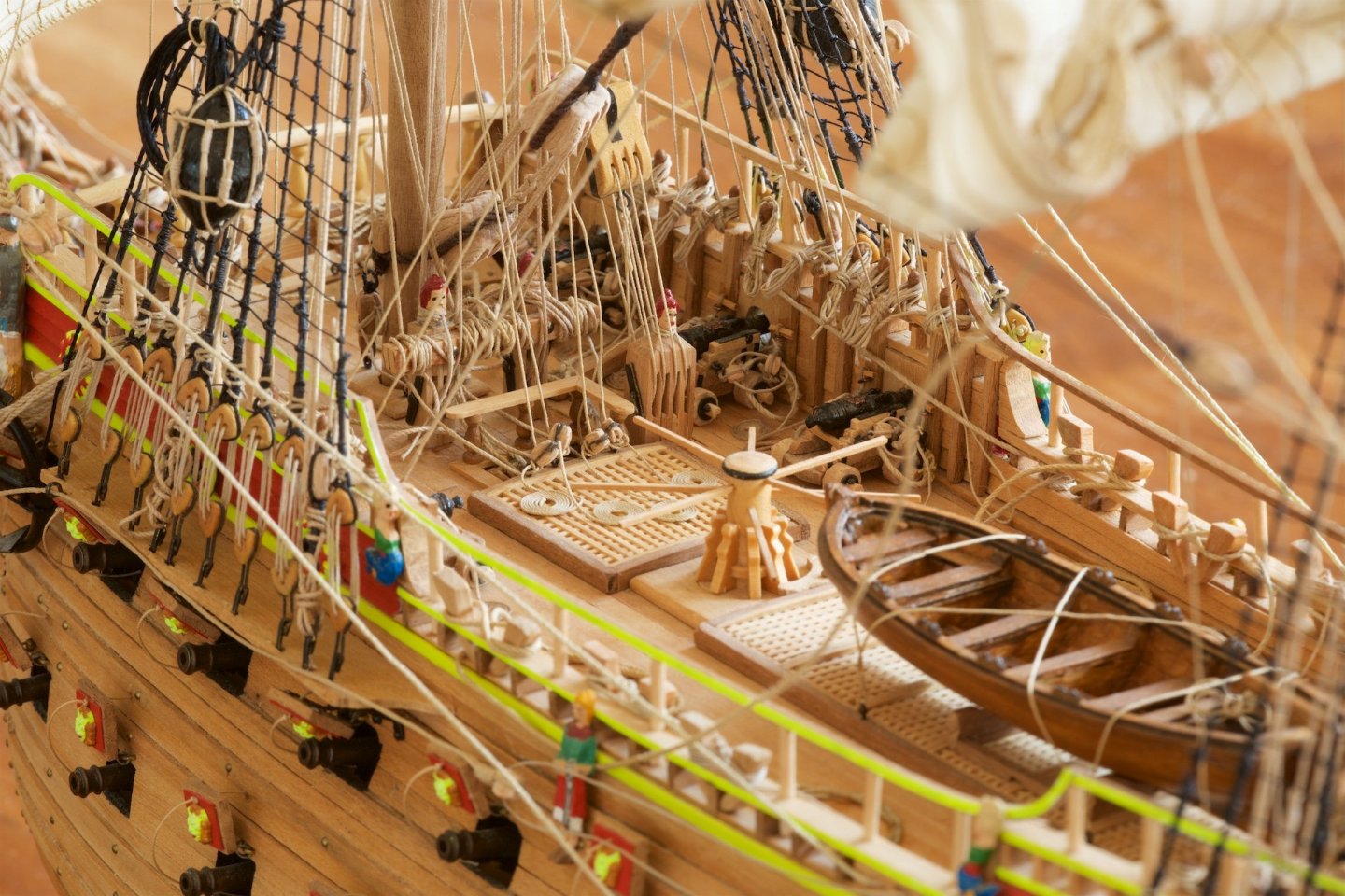
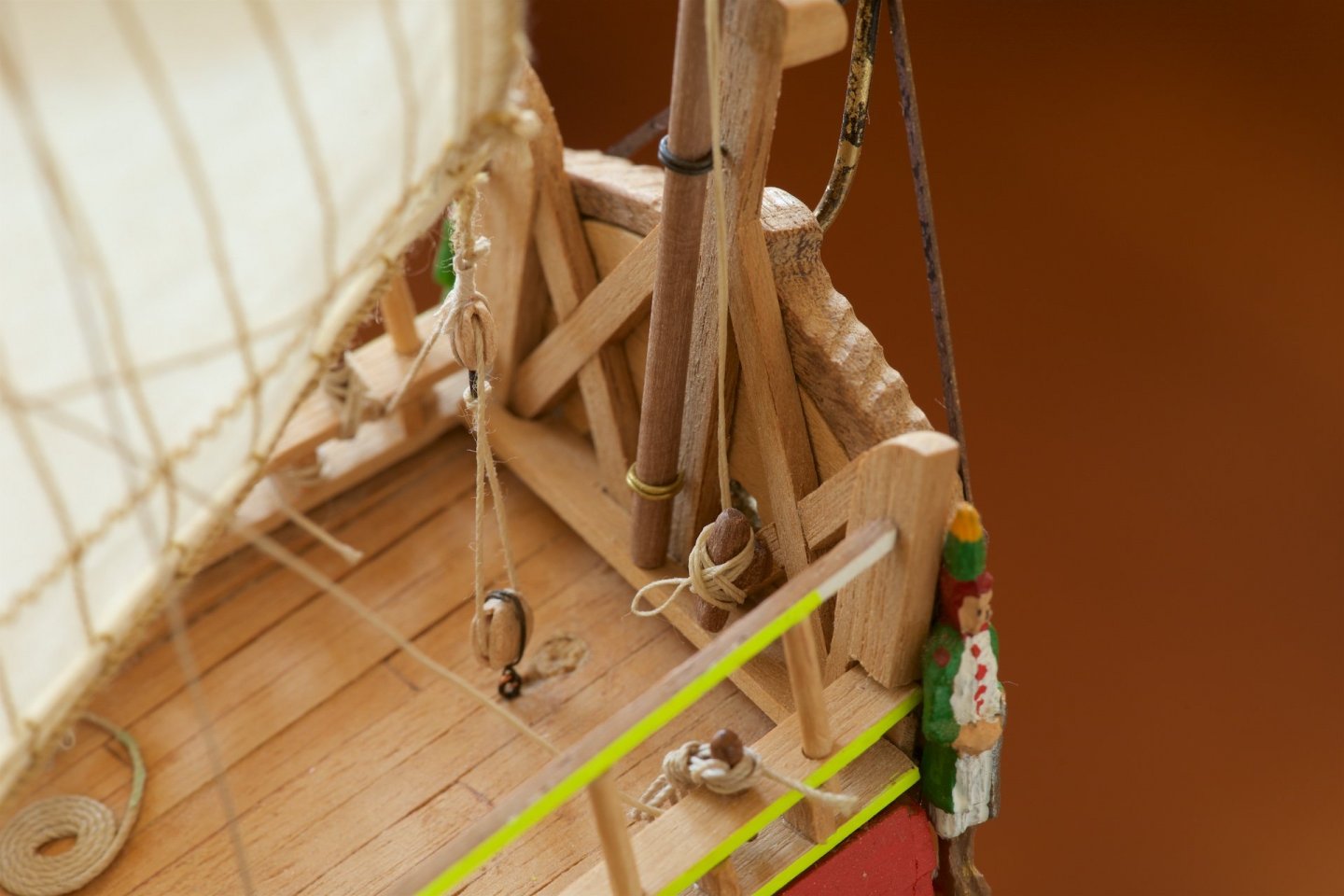
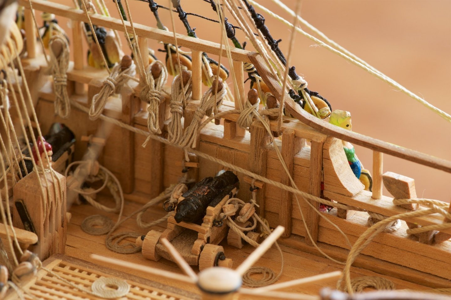
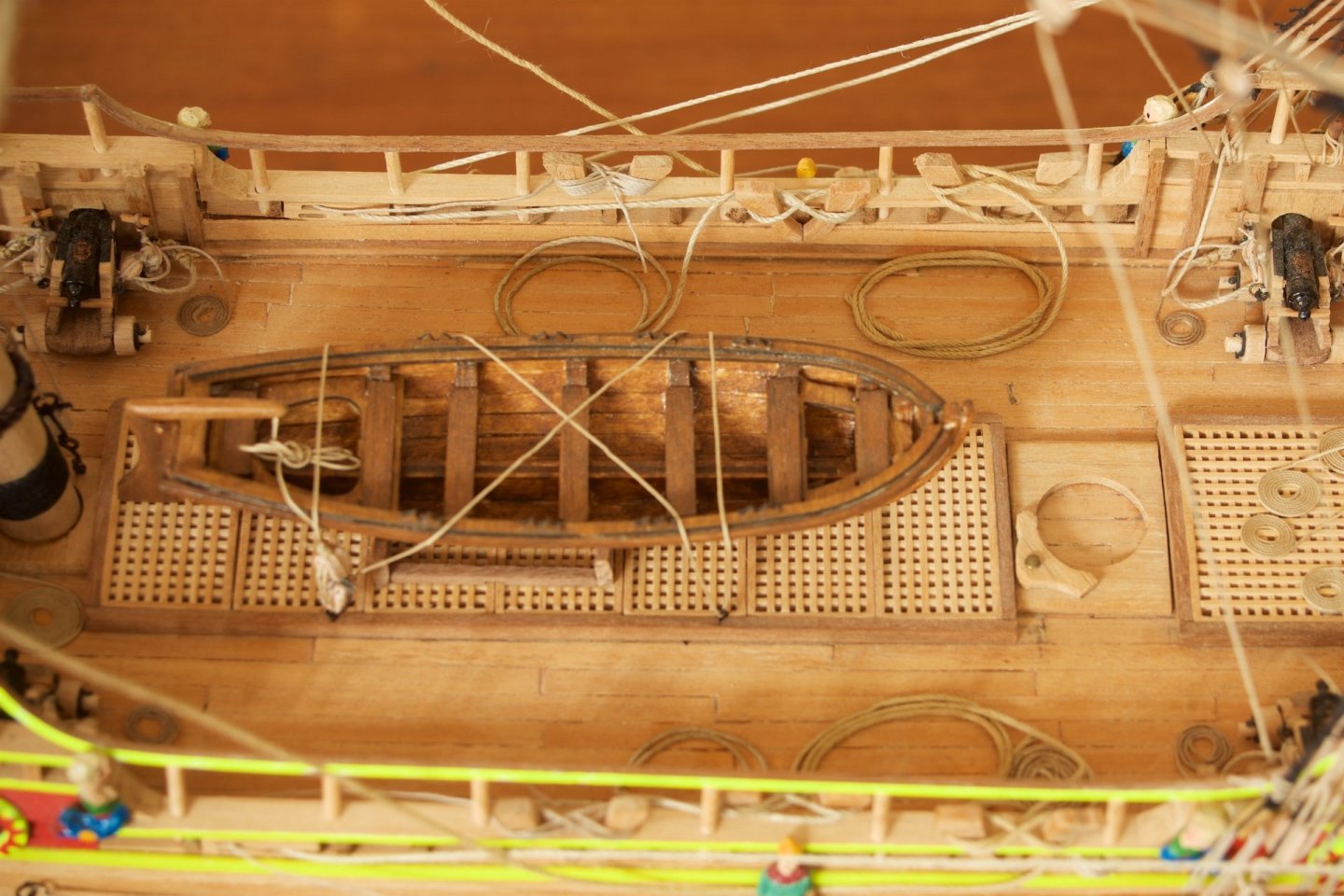
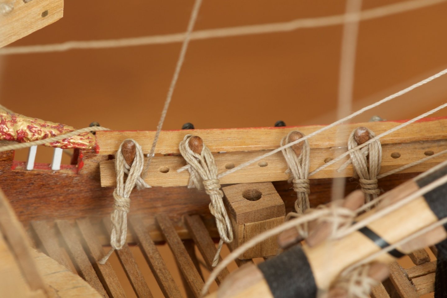
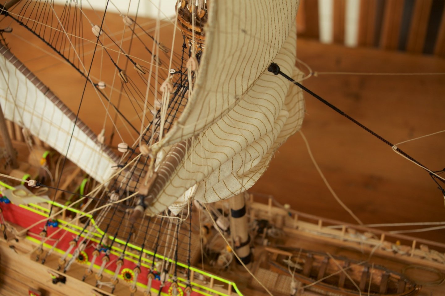
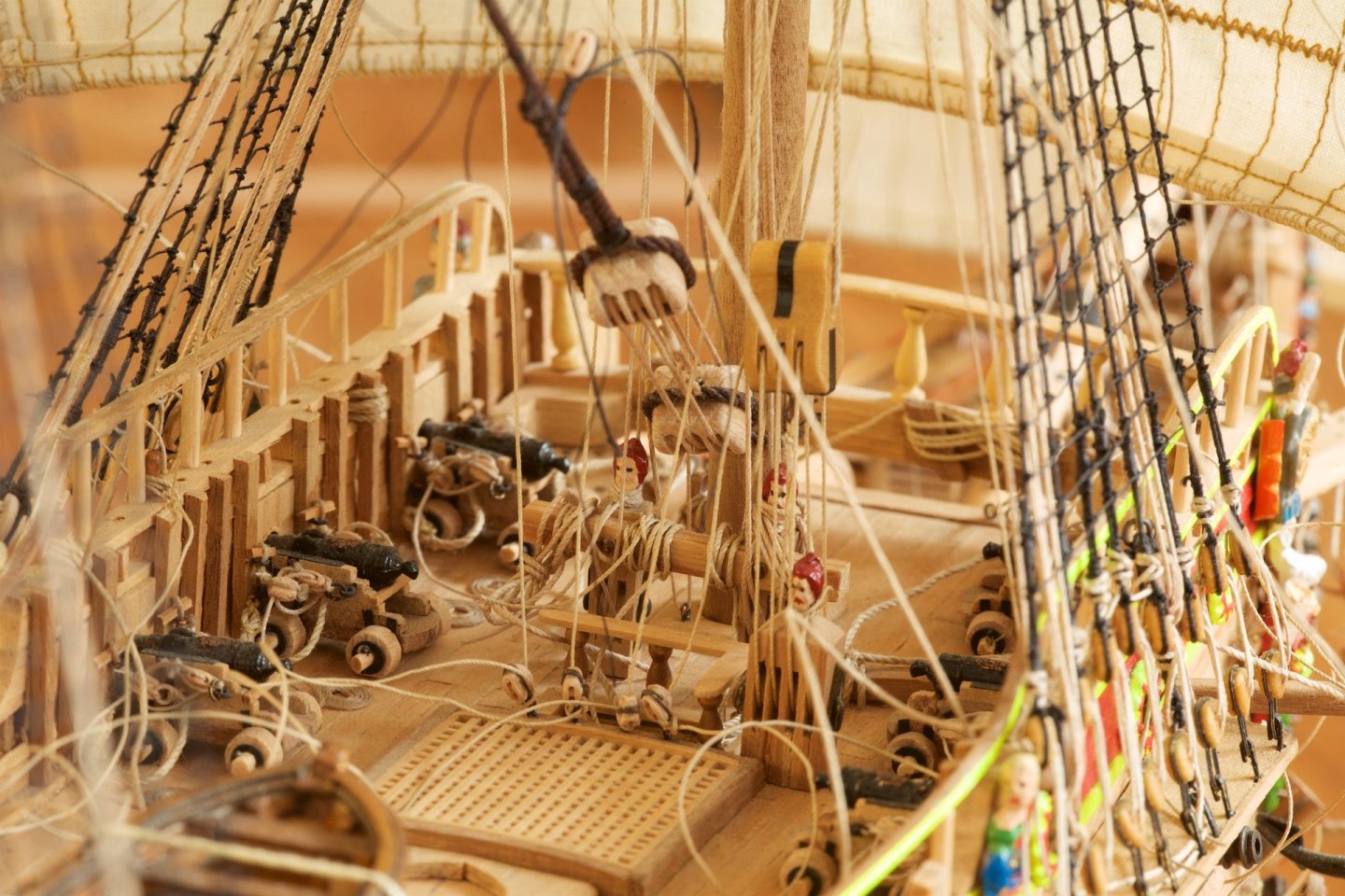
I added lines/coils/ropes to the belaying pins, using the pin method. First the rope a few turns around the pins, under 90 degrees angle, and then made some turn-arounds to tye the rope together. I used a needle underneath to have some space under the ropes to pull the ropes underneath. It makes the appearance of the belaying pins much better, but it is also a pity that this hides the 'real' belaying knots.. Also a picture of the deck, with the coiled ropes, from the sheet lines of the lower sails, on deck.


-
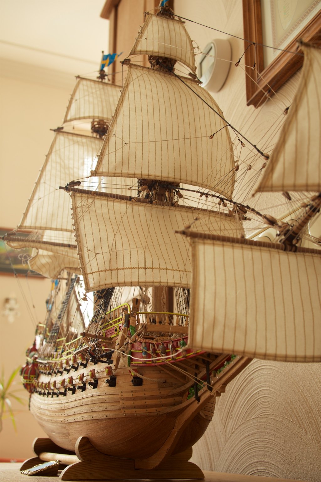
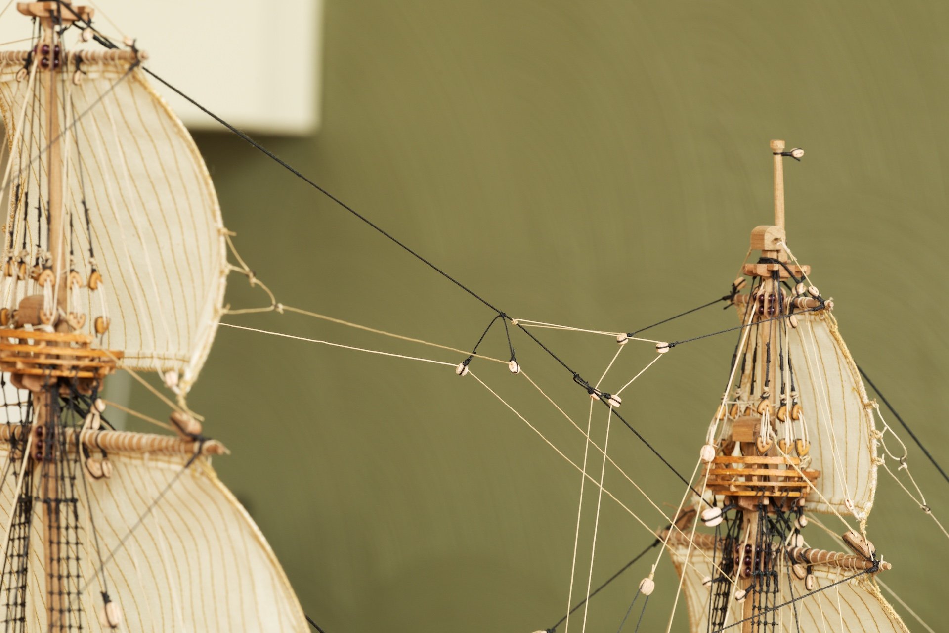
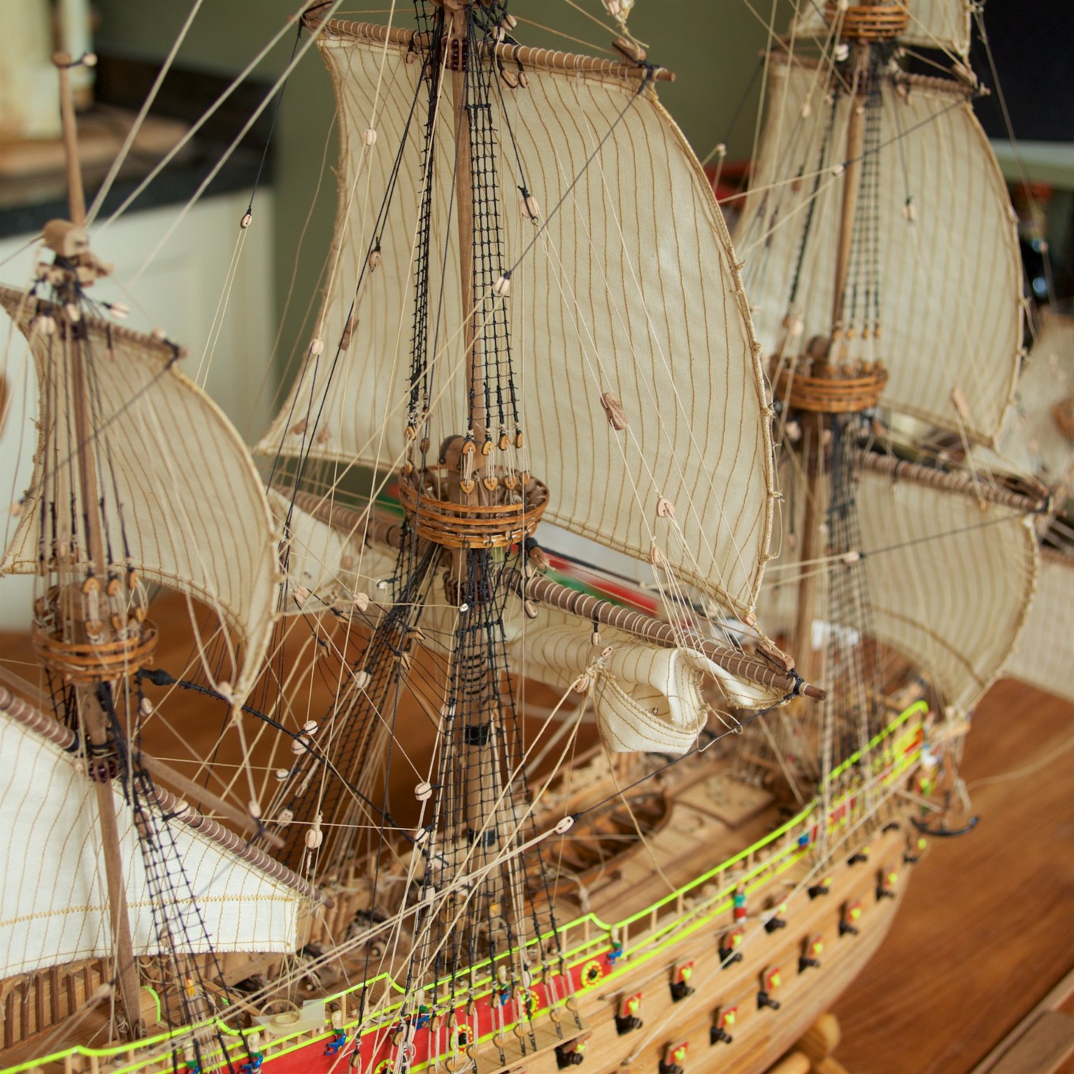
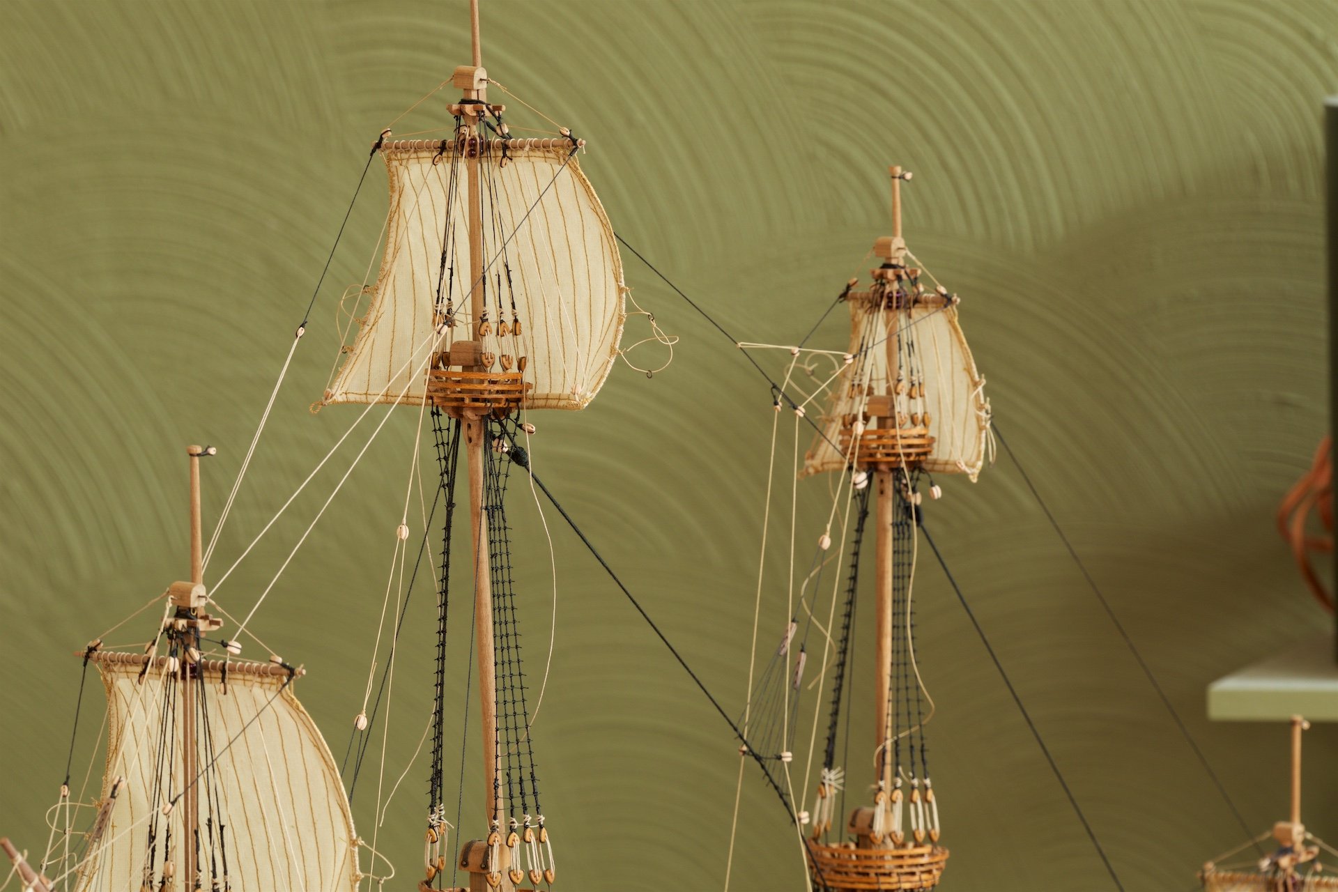
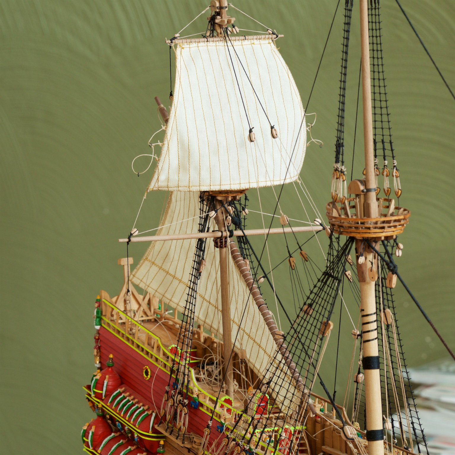
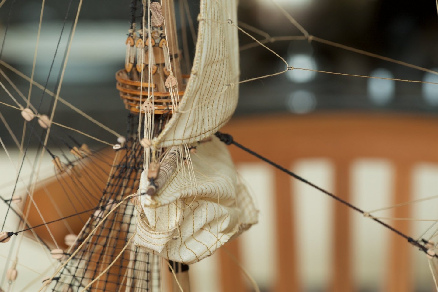
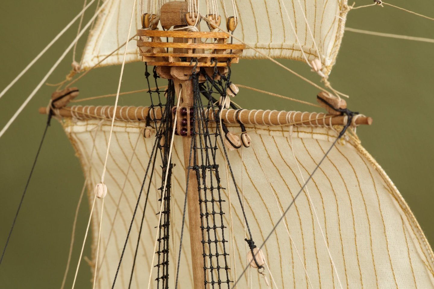
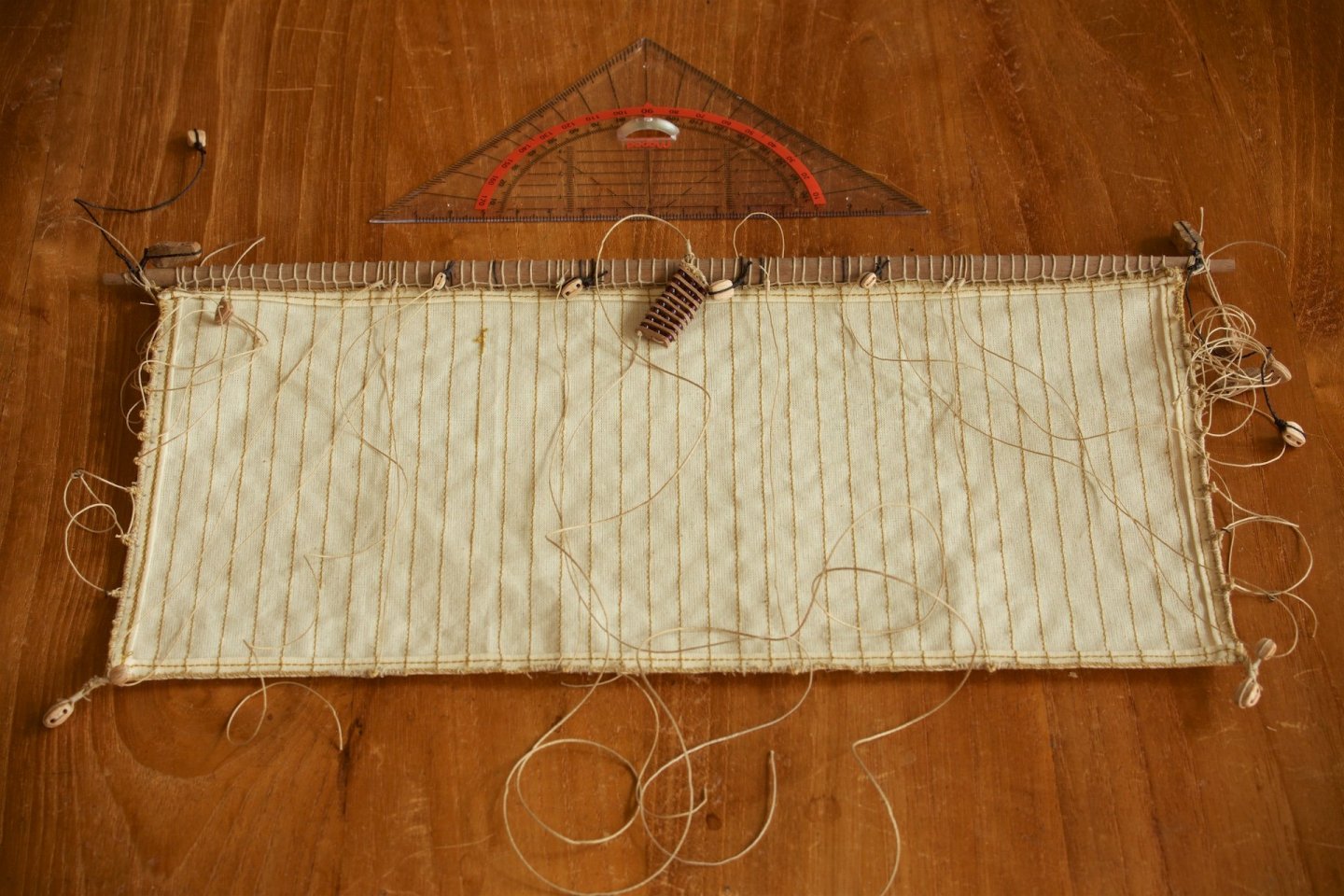
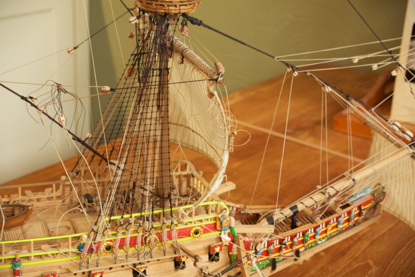
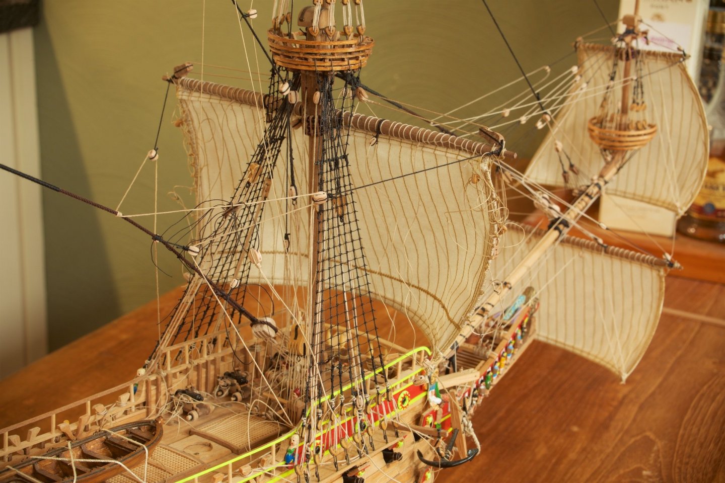
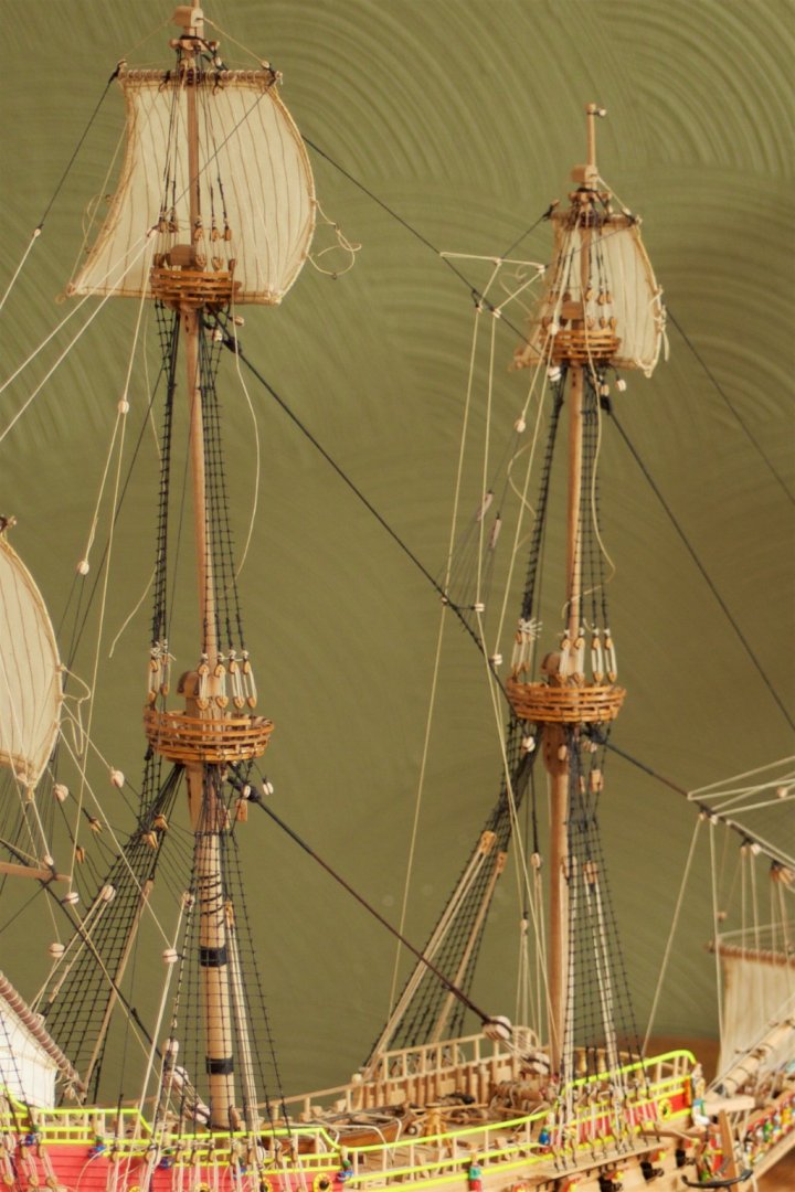
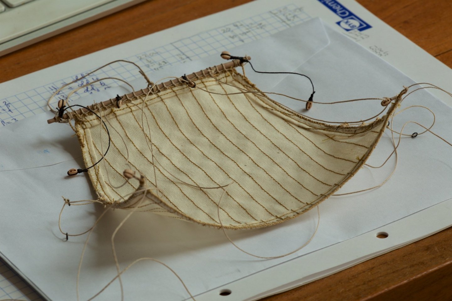
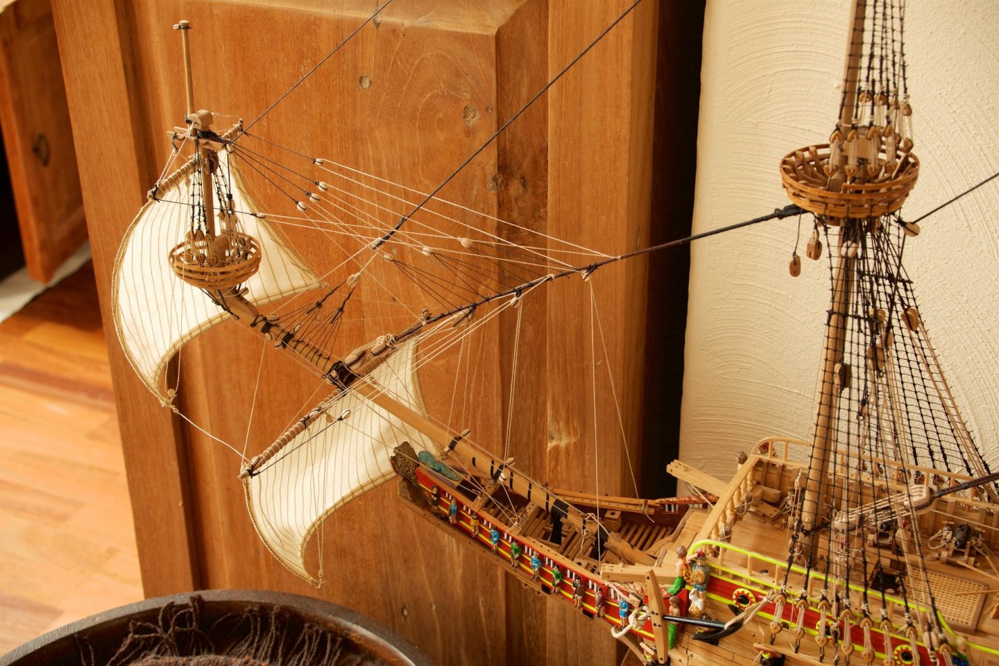
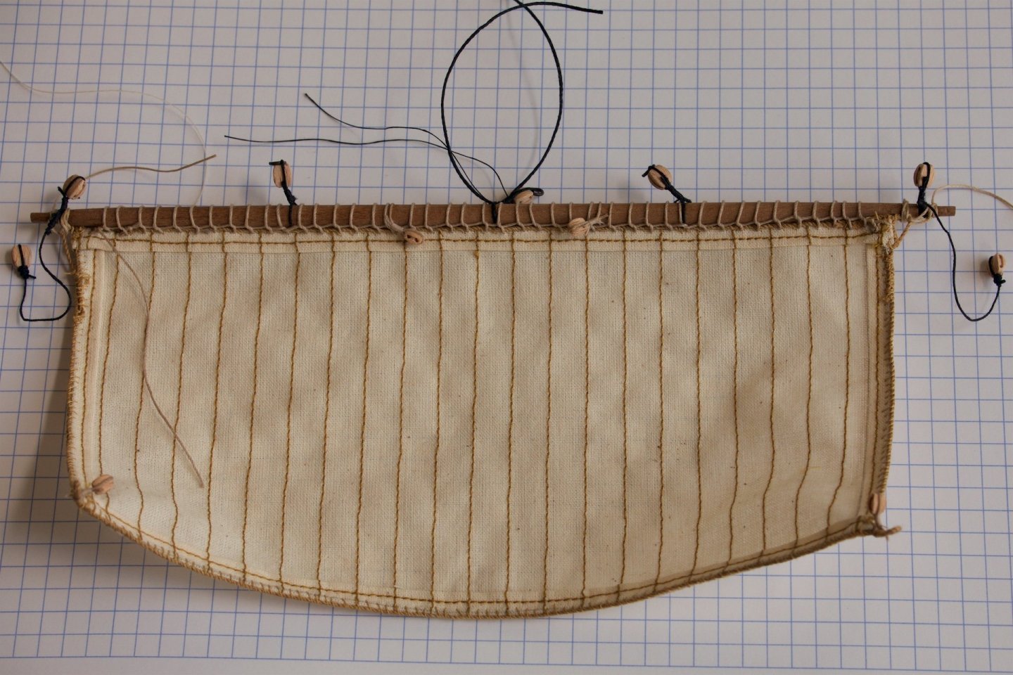
The main topsail was the last sail to mount. As most of the sails, I had inserted copper wires to give the sail curves, to simulate wind. Without the sheet lines to the yard below, the curvature is actually too much. Attaching to the yards results in a nice wind-like appearance. The sheet lines, from the topsail through the violin block to below had to have a lot of tension to bent the sails close to the yard. With the topsail installed, I could also fixate the lower yard and then hoist the bunt lines and clue lines to have the main sail semi-folded. My attempt was to simulate the Vasa Museum 1:10 model, but my sails are of too thick and stiff fabric to have the sail hang like that. But I am happy with the result anyway. Meanwhile also installed the bowlines of the main mast sails and also the sheet lines of the lower sails.


-
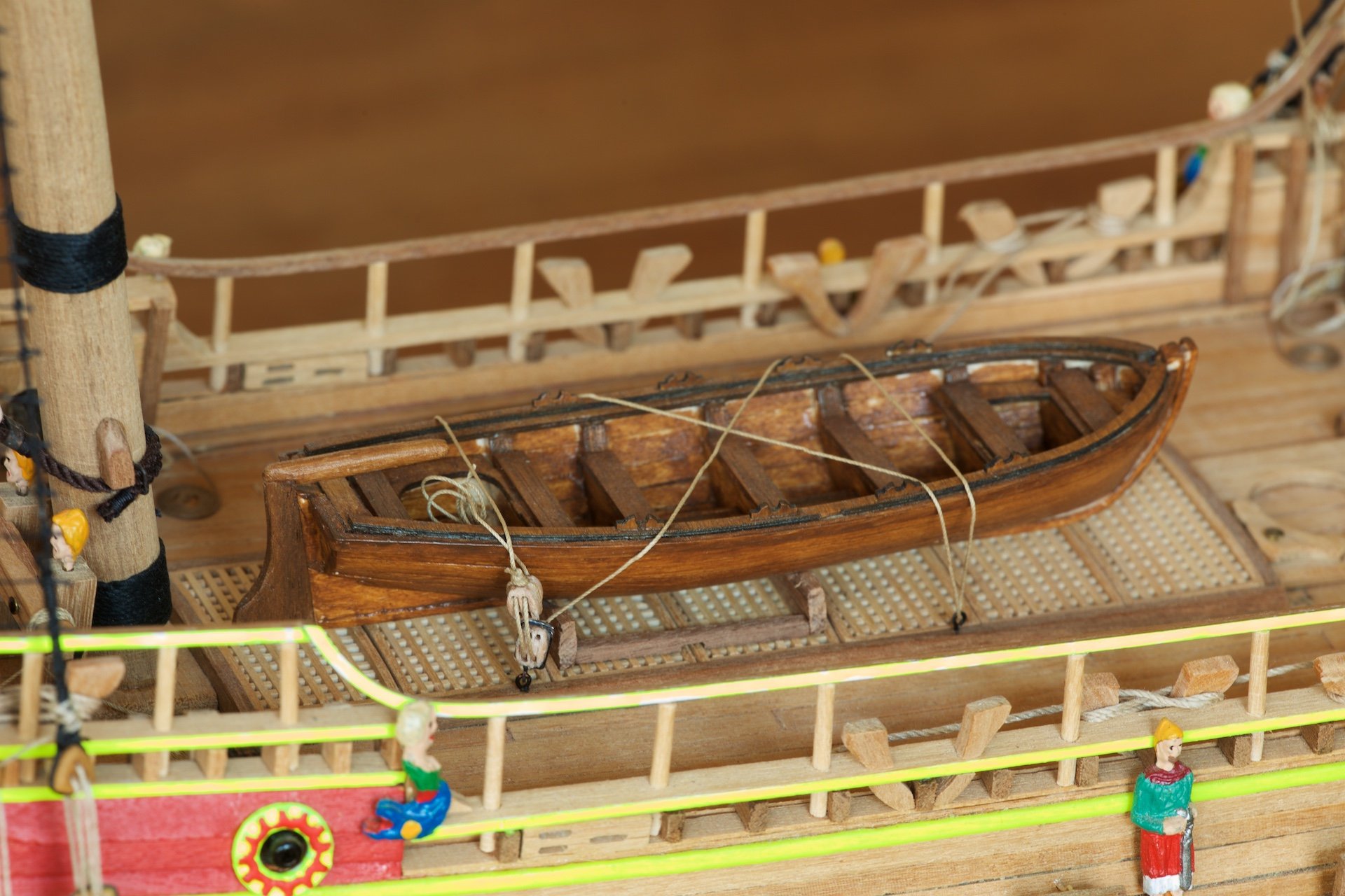
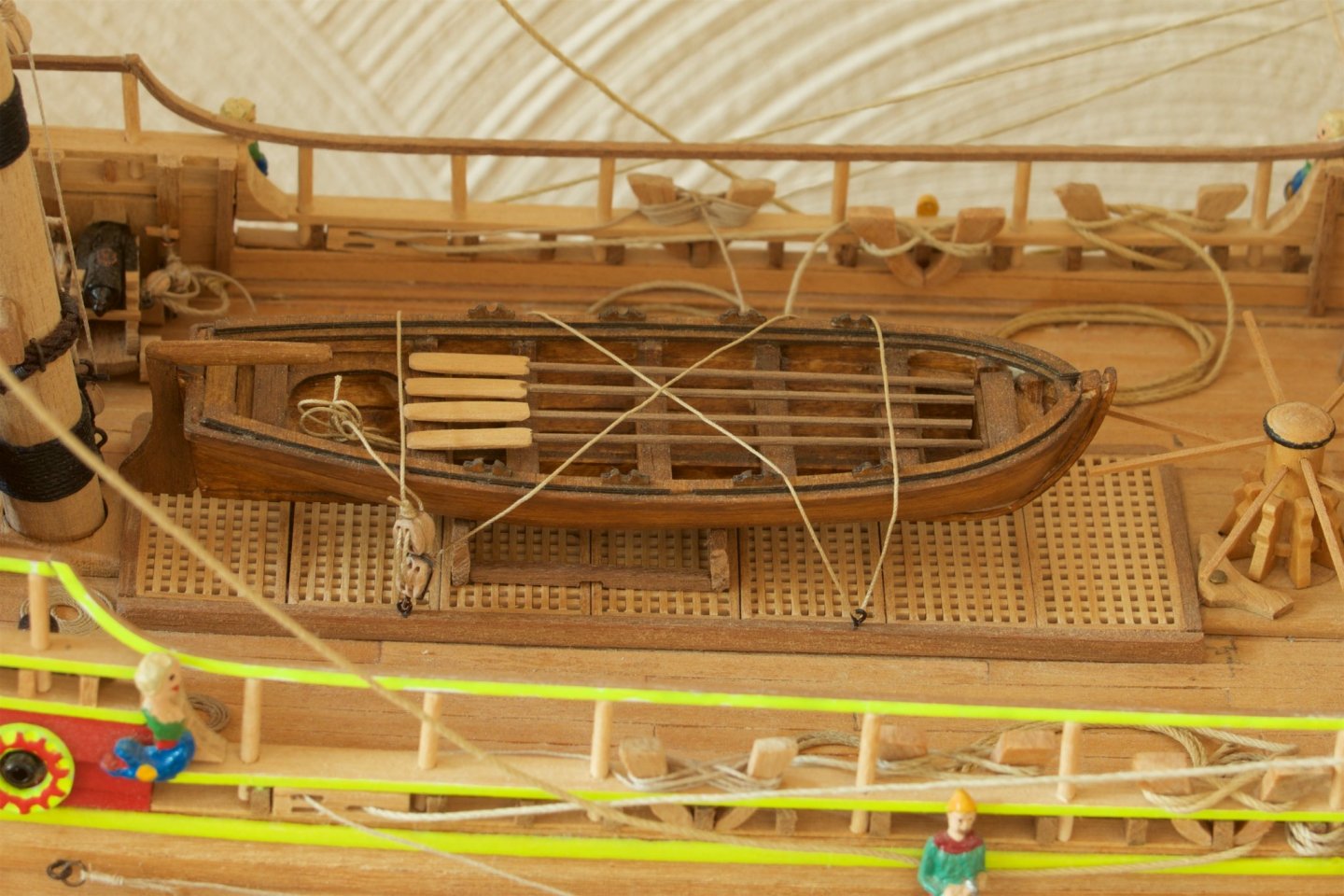
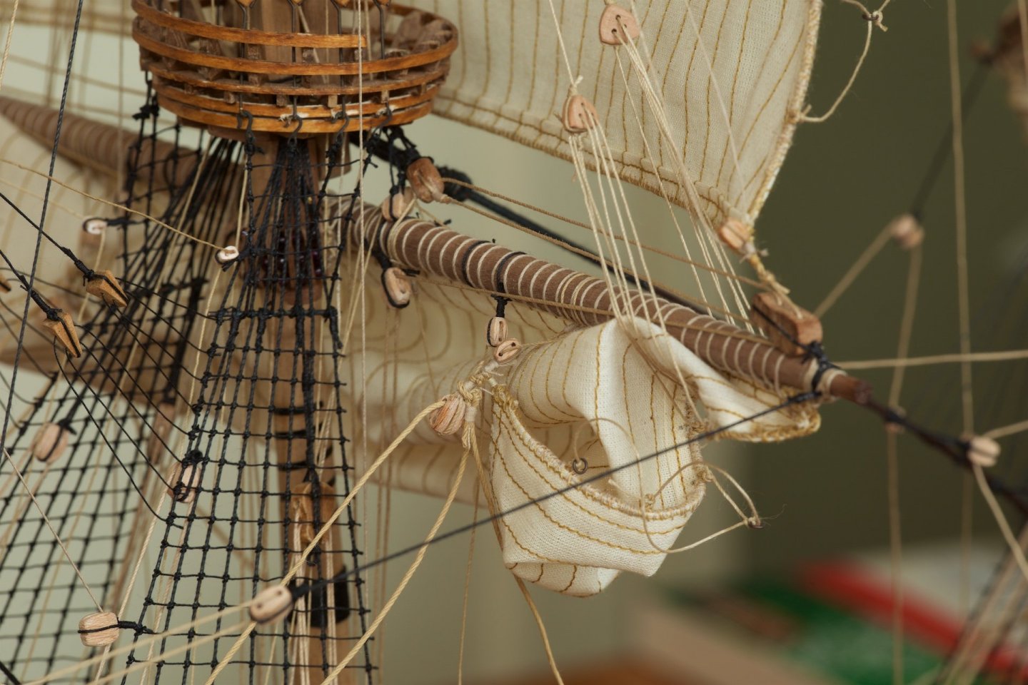
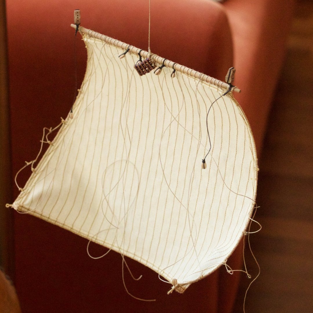
Before I started with the masts, I had installed the life boat. Having in mind the ropes and blocks that I used for the sails, I wanted to reduce the size of the blocks and ropes of the life boat. So I did. Pictures of before and after. Also the main sail was made and installed. This one without the copper wires and thus without curve. This because I intend to have this sail partly folded, as in the 1:10 model in the Vasa Museum. Before mounting the sail, first all blocks and ropes were attached. I wait with tying all the lines and with the folding until I have also installed the main topsail, because the combination of main sail and top sail ensures that they are fixed in place, which will help me to have/keep the yards horizontally...


-
Thank you for the compliments! I was using the plans from Corel for most of the standing rigging, but I have adapted where I had seen adjustments made by Micheal here on MSW (md1400cs). I looked into the Zu Mondfeld book for the details on how to do things. The plans from Corel have no sails, so I looked at the example set by Michael and have also been looking very carefully at the photos of the Vasa Museum 1:10 model and the drawings from Billing Boats, that do include the sails and lines. In addition, I wanted that the lines going to the belaying pins do not cross, so i had to plan and sometimes redo the lines going to the belaying pins to have the ropes/lines running parallel.
-
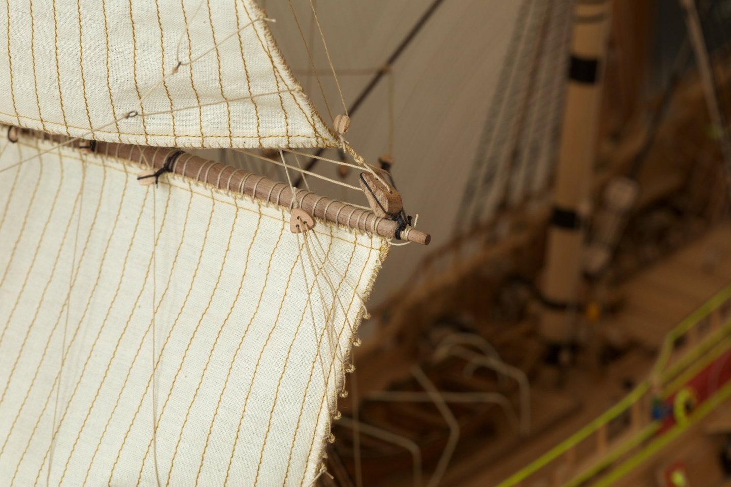
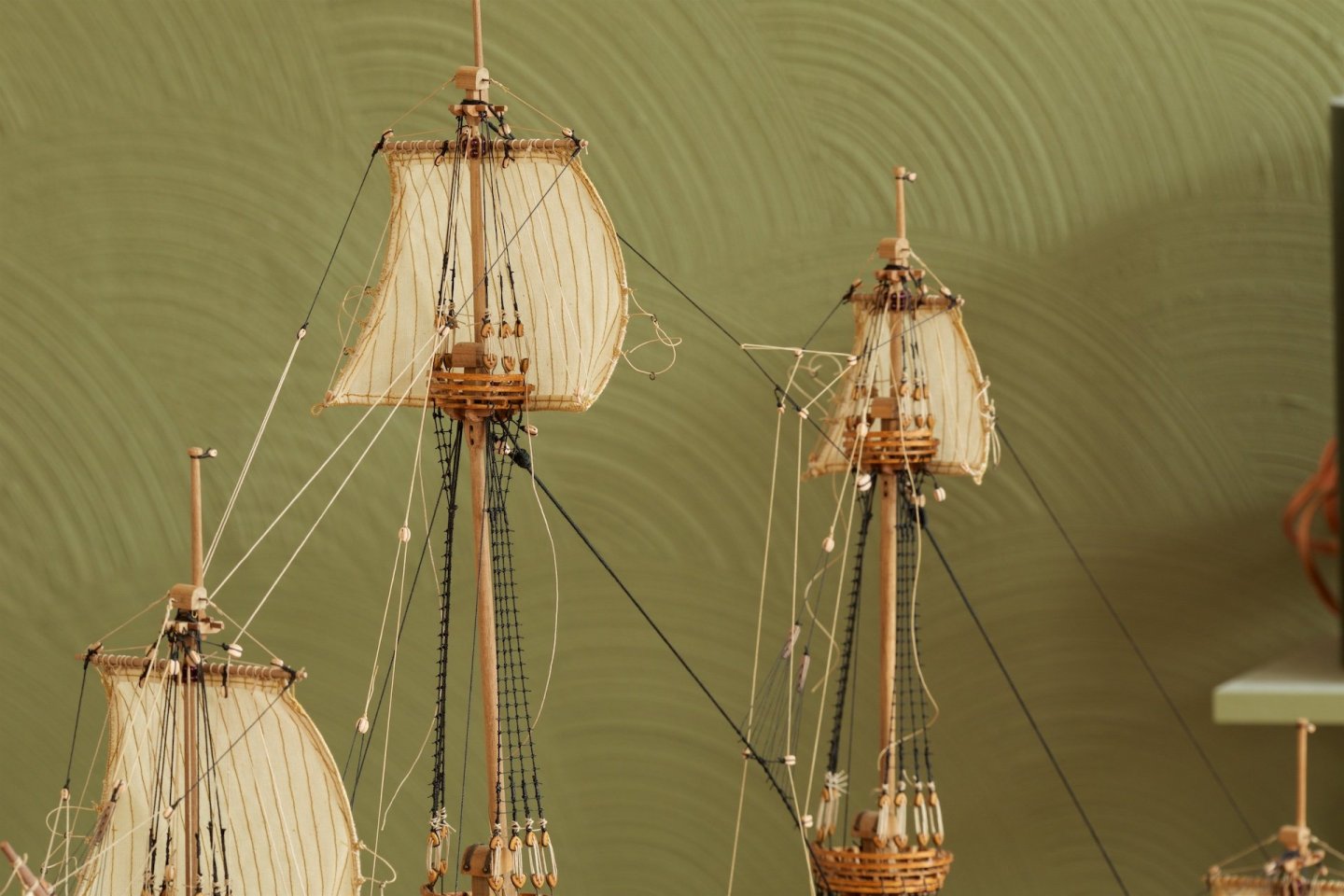
Also the last sail of the foremast, the topsail (the middle one), has been installed. This sail has a nice curve in it, due to the copper wires in the seams. The lower sail bent somewhat too much to the front, in my opinion. But I do not like to add a small rope to tie it to the mast... Also the bowlines of the three foremast sails installed, using 4 mm blocks. Missing still is the sheet line from the (lower) foresail. The buntlines on deck have been tidied by making flamish roles. The lines at the belaying pins have been cut short now. Lateron, I will add line bundles. The area beneath the first flatform is very crowded with blocks and lines...


-
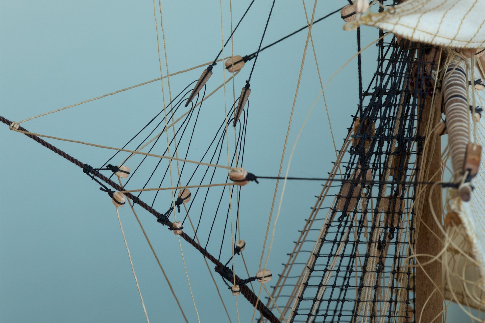
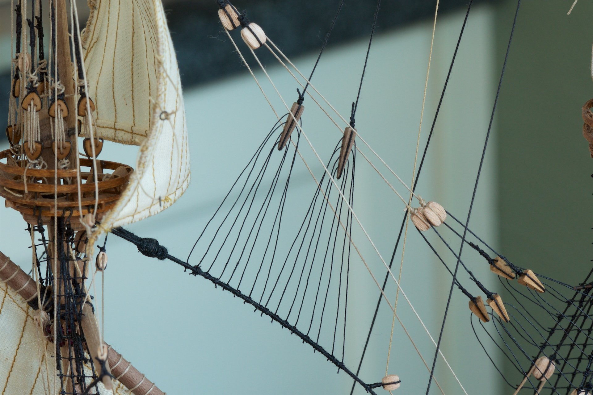
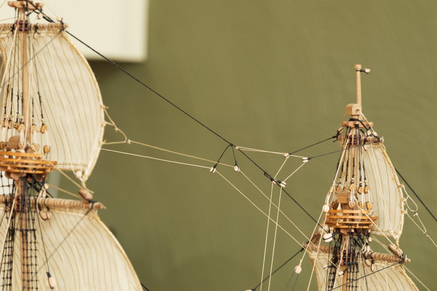
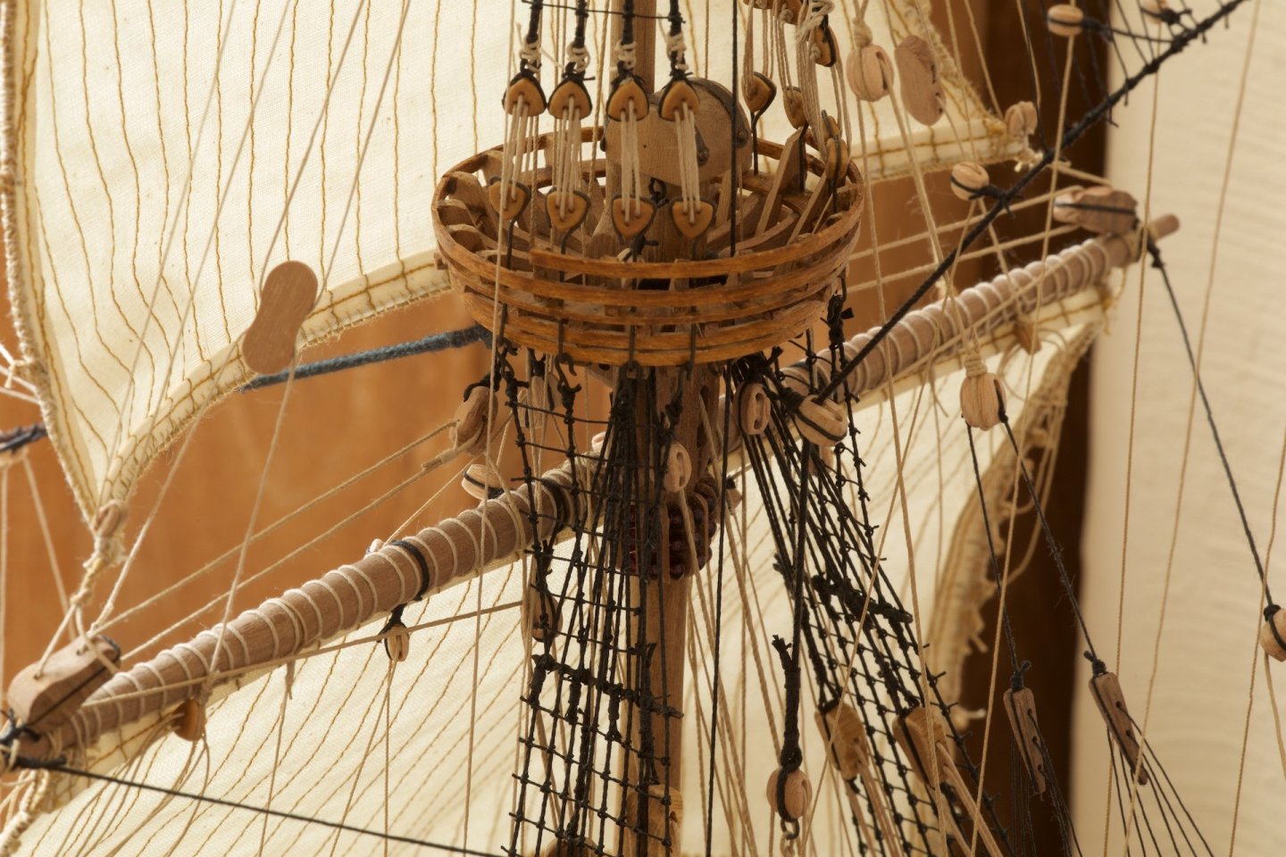
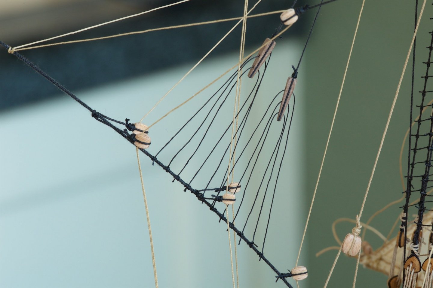
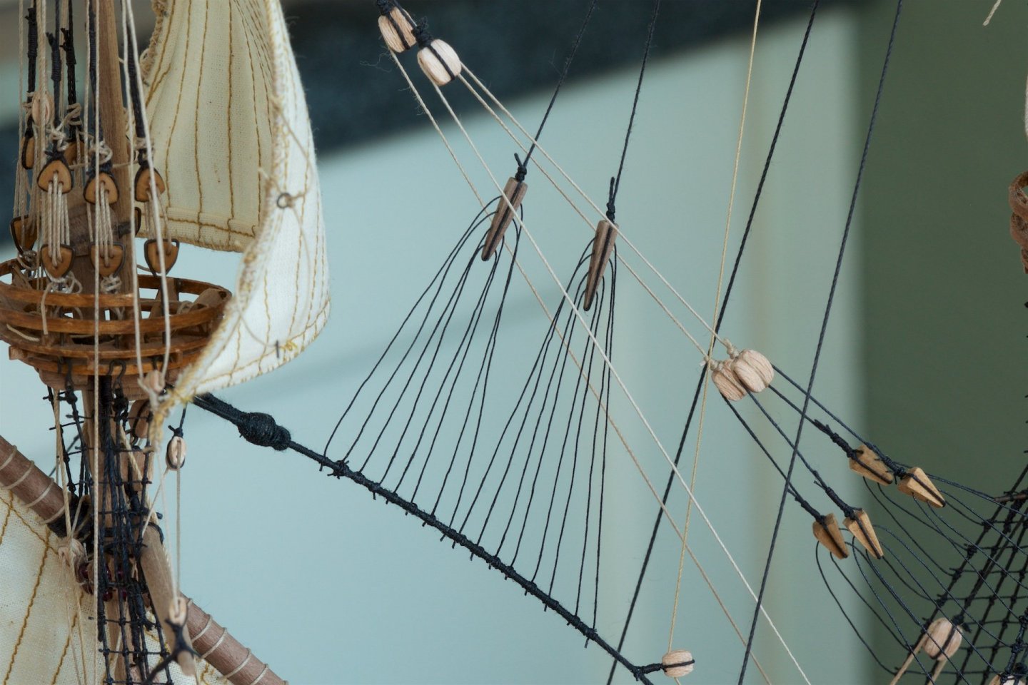
The next sail is the foremast sail. The one in the middle, the topsail, will be done next. There are now many lines/ropes running from the mast and the yards to the deck. The lifts are attached the wooden pilars on deck. The bunt lines of the foresail are attached to the 4 blocks on the deck. The clewlines, the leechlines and the braces are attached via belaying pins on the railing. The first spider attachment, I had made a mistake by making 8 lines per spider, which makes it more complicated to put tension on all of the ropes. This was the one that I made for the topgallant of the main mast. The next spider, I did make it with 6 ropes. This one was for the topgallant of the foremast. The third spider, I did differently: I did not make the 6 lines from 3 ropes, but made it from one rope and I pushed it with needle through the stay. This way, it is easier to put tension on all lines, because the lines remain adjustable. This spider is for the topsail of the foremast.

-
Meanwhile also installed the topgallant sails on the main mast and the fore mast, except for the bowlines. The lines for the lift are tied to the deadeyes on the platform and also the clewlines will be so. This makes them more or less independent from the rest. There are several belaying plans for the Wasa, and I have taken this configuration from the plan that I found in the built-log of md1400cs. I noticed, that in the Billing Boats plans, also the lines from the topgallant sails go to the belaying pins in the railings. The halyards are both connected via spiders to the stays. For the main topgallant sail, I made a 8-line spider block, which was actually a mistake that made it more difficult. I realized later that all plans show 6-line spider blocks, and I made thus 6-line spider blocks for the foremast topgallant.

-
The topsail of the mizzen mast has meanwhile also been installed. The crossjack only has braces and no lift, so having the crossjack horizontally was not so easy. I finally did so by putting a lot of tension on the sheetlines of the topsail with which I could get the crossjack horizontal. Also the start of the bowlines added to the topsail using rings and not blocks, but not the bowlines themselves yet. This will be done later.

-
I have been attaching the sails to the yards, including most of the blocks. This so that it is easier once the yards&sails are attached to the masts. The sequence of installing yards&sails is a matter of choice, but I decided to start with the mizzen mast, because it is more or less standing on its own. I made the mizzensail to have eyelids from rope, to install the bunt lines, before adding the sail to the yard. The mizzensail is attached to the mast including the parrel, which is with a block leading to a ring at the base of the mast. The spider part at the top of the mizzen yard was made from one continuous rope, because I milled some space beneath it, so that the tension is always divided among all lines. The hailard, the parrel-rope (tye) and the line coming from the spider-part are all attached to (three) rings at the base of the mast. The ropes at the belaying pins and on the deck still need to be wound up, but I save that until I have attached more sails. At present, I have not fixed the knots with diluted glue, so that I can adjust tension later on.


-
Hi Micheal, I also ordered the (2) sets of microshapers. Thanks! Andre
-
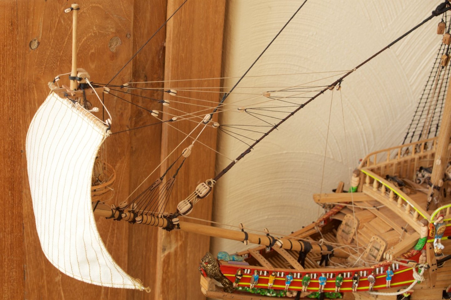
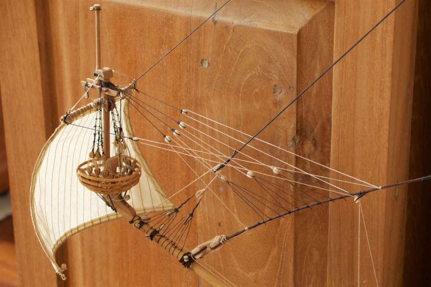
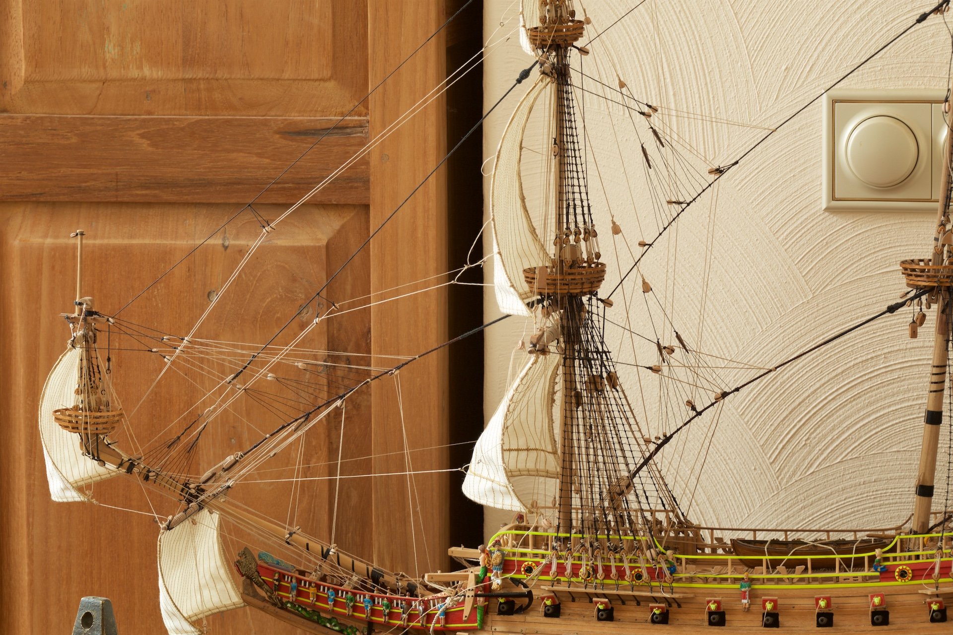
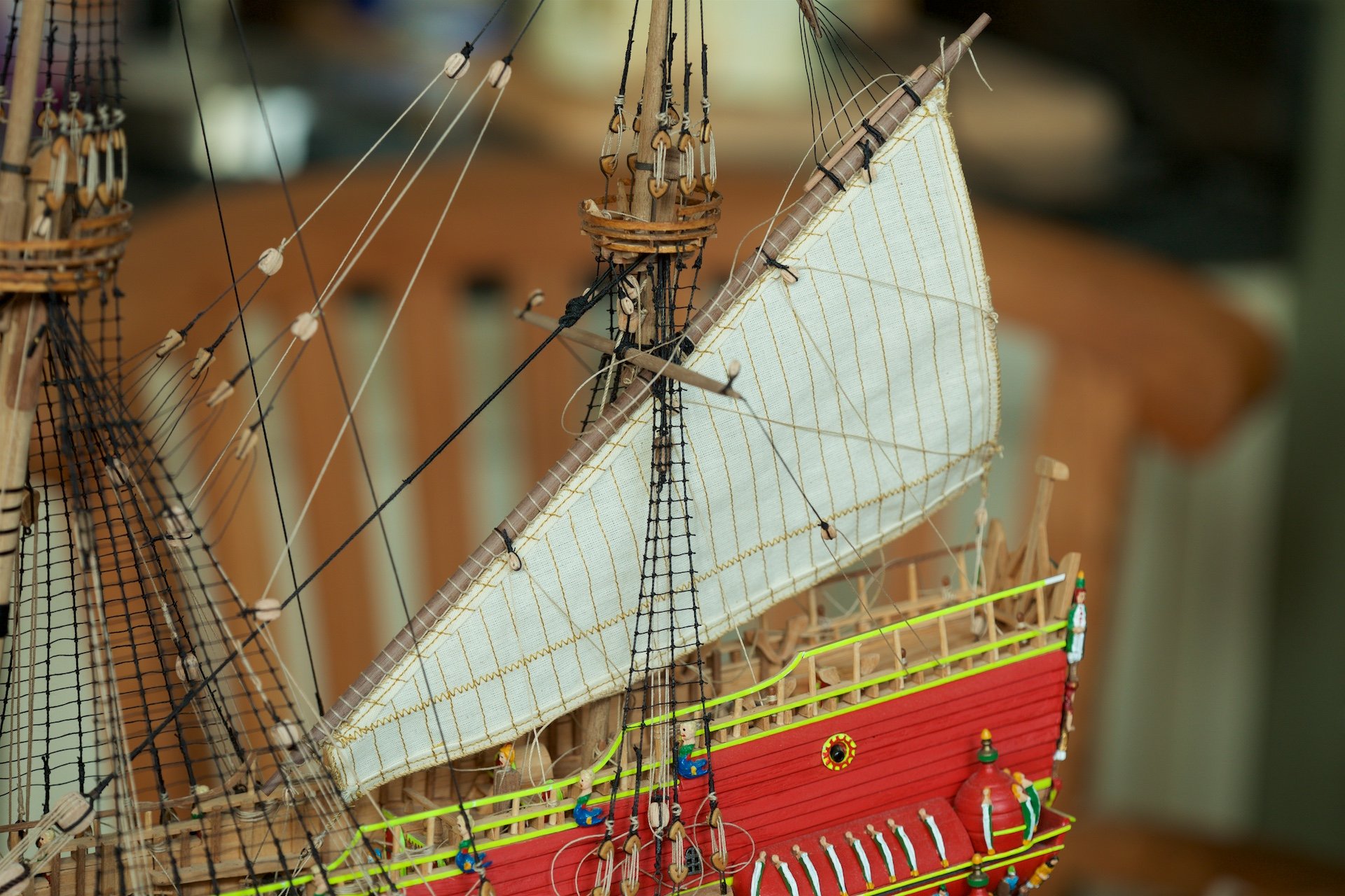
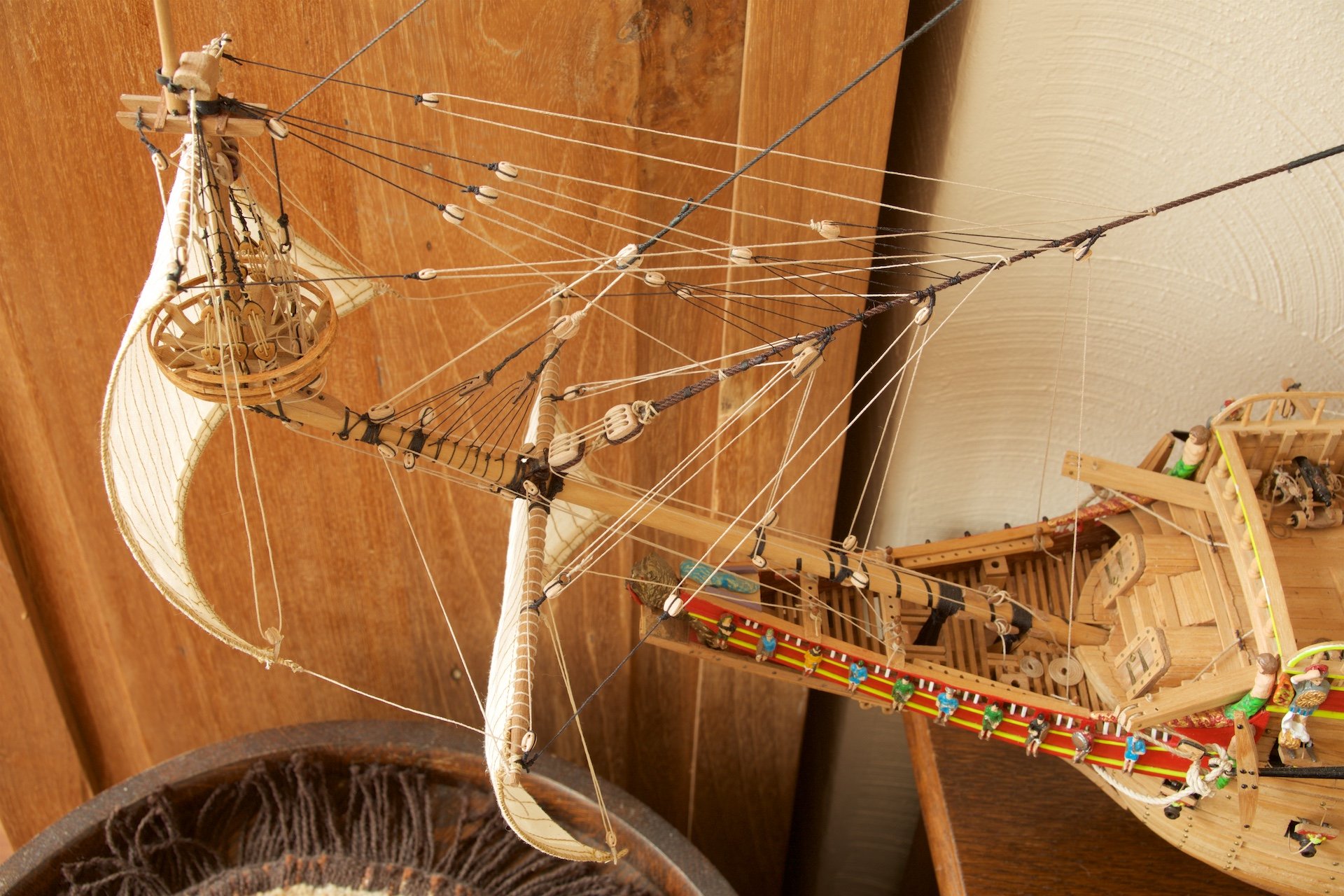
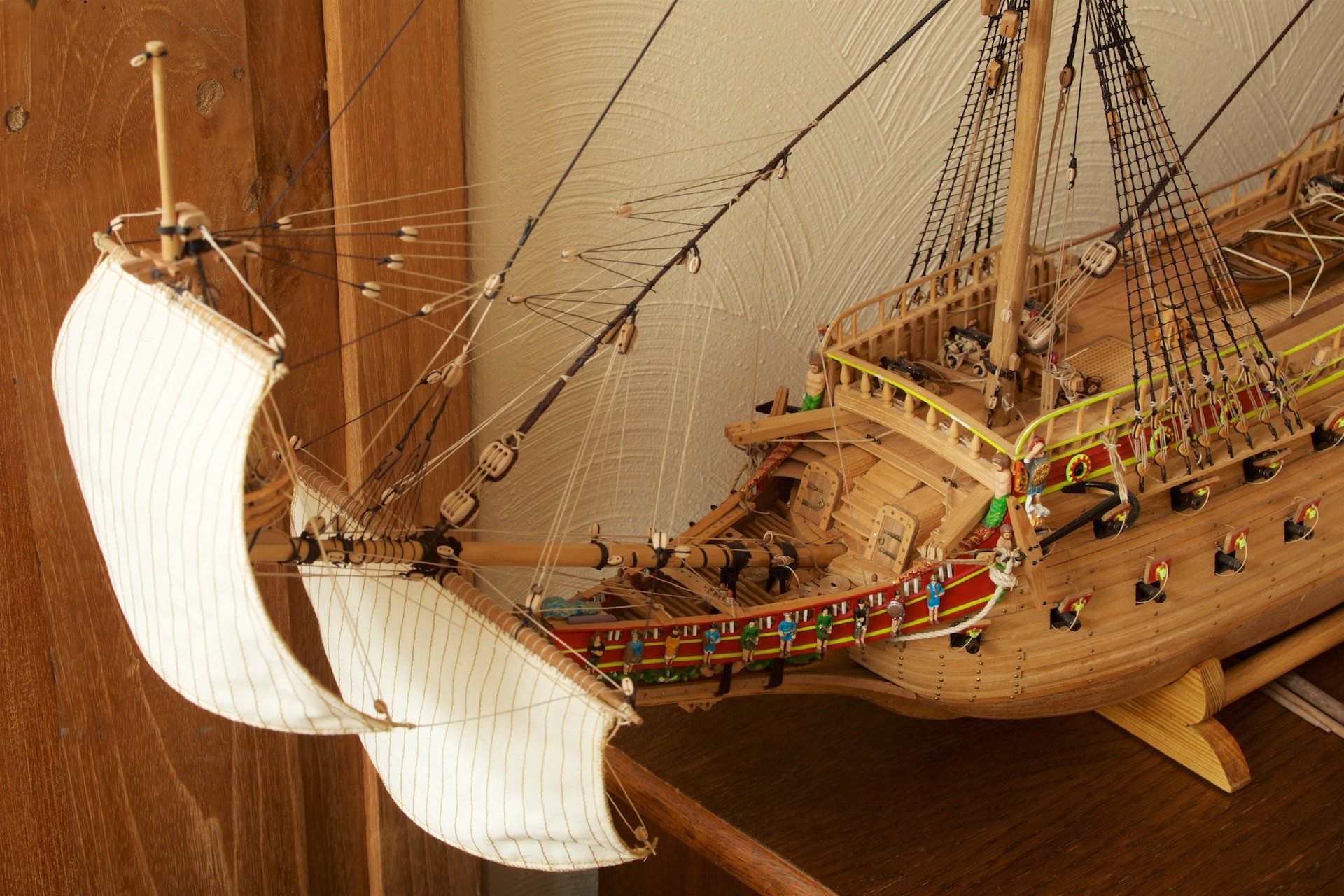
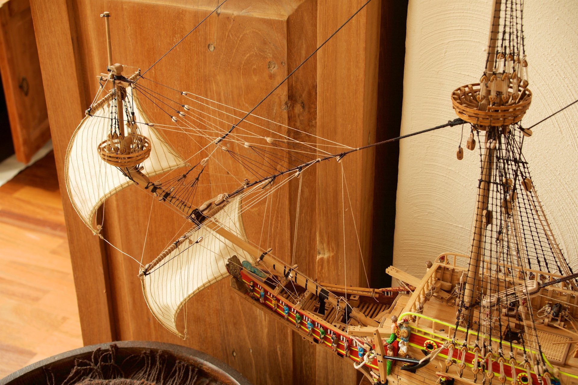
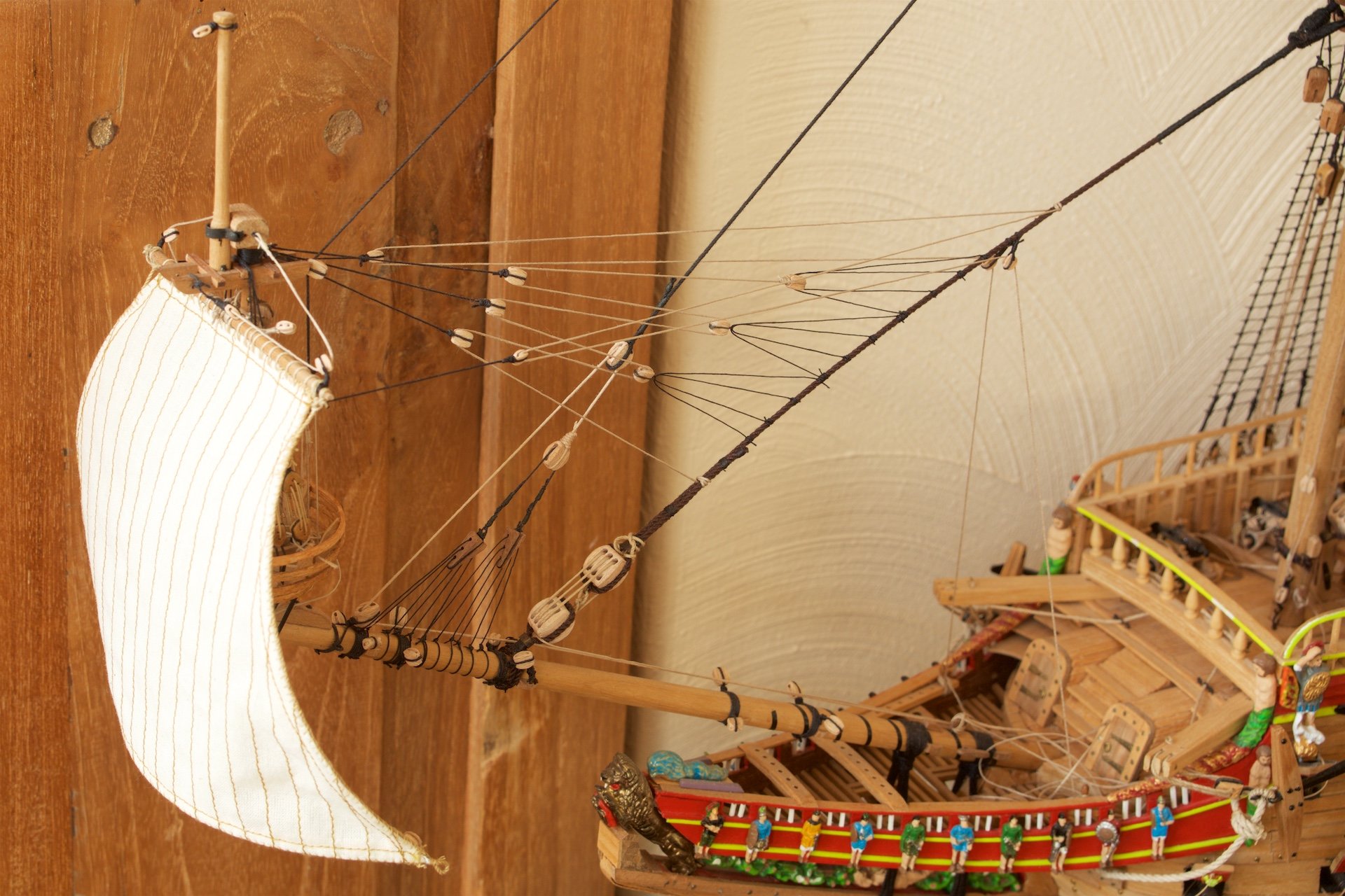
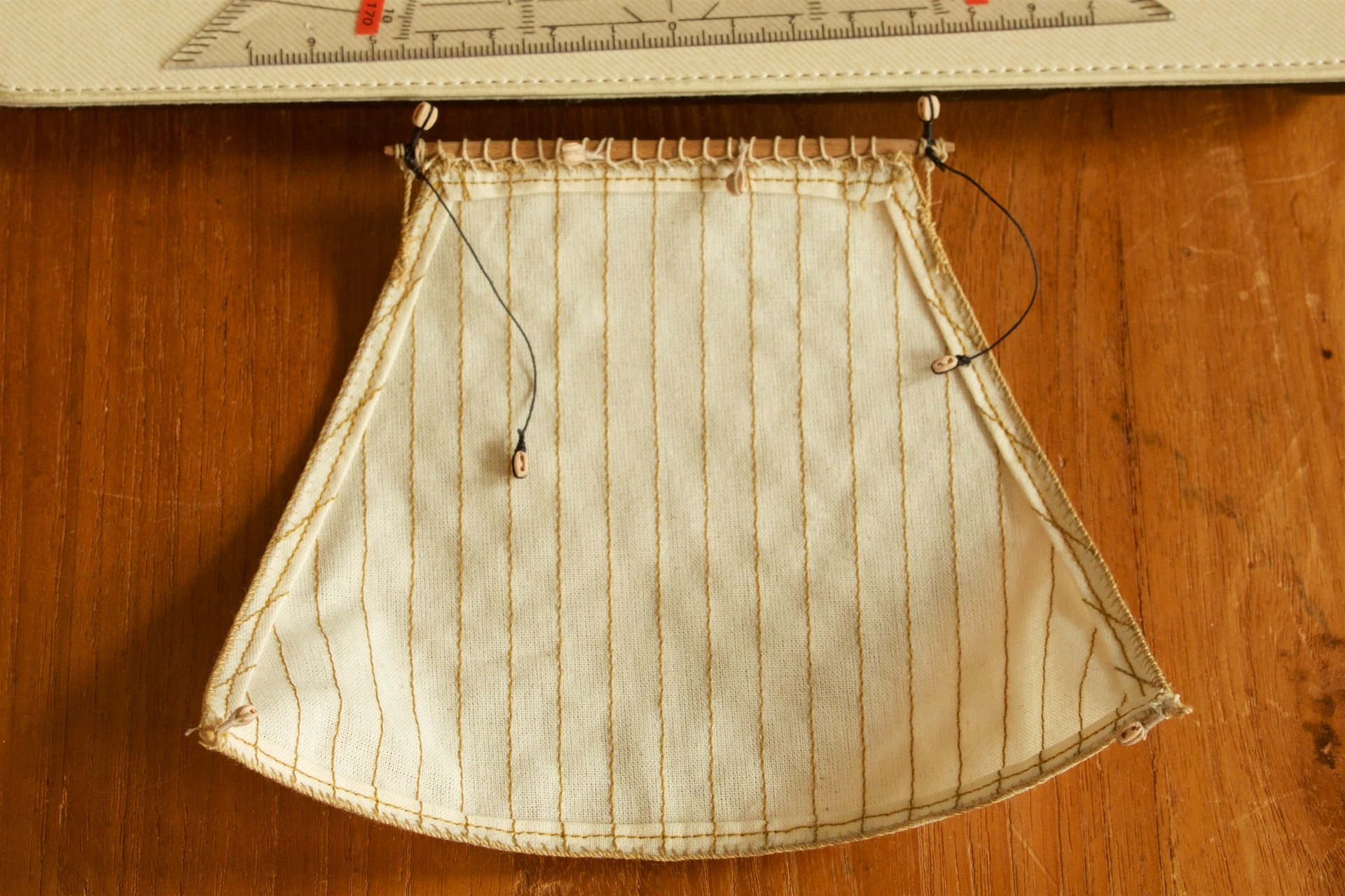
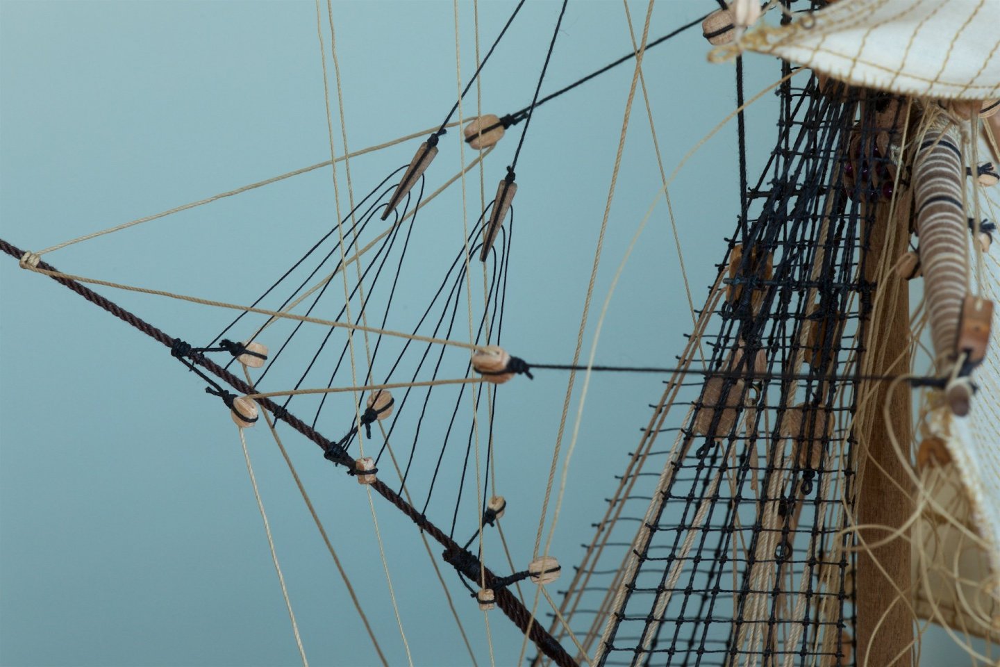
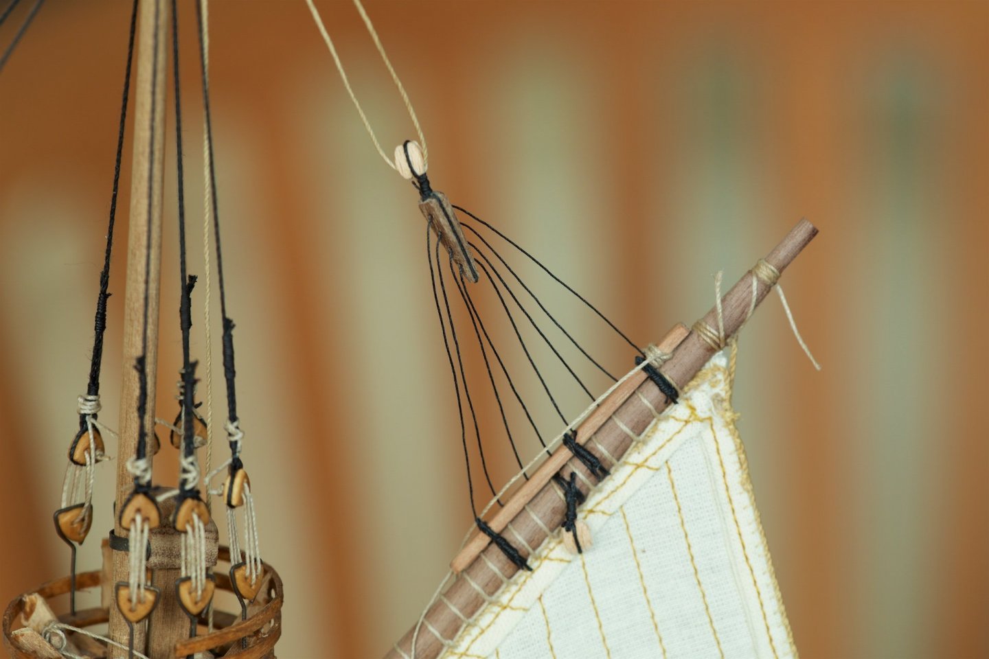
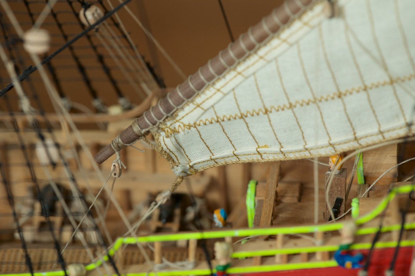
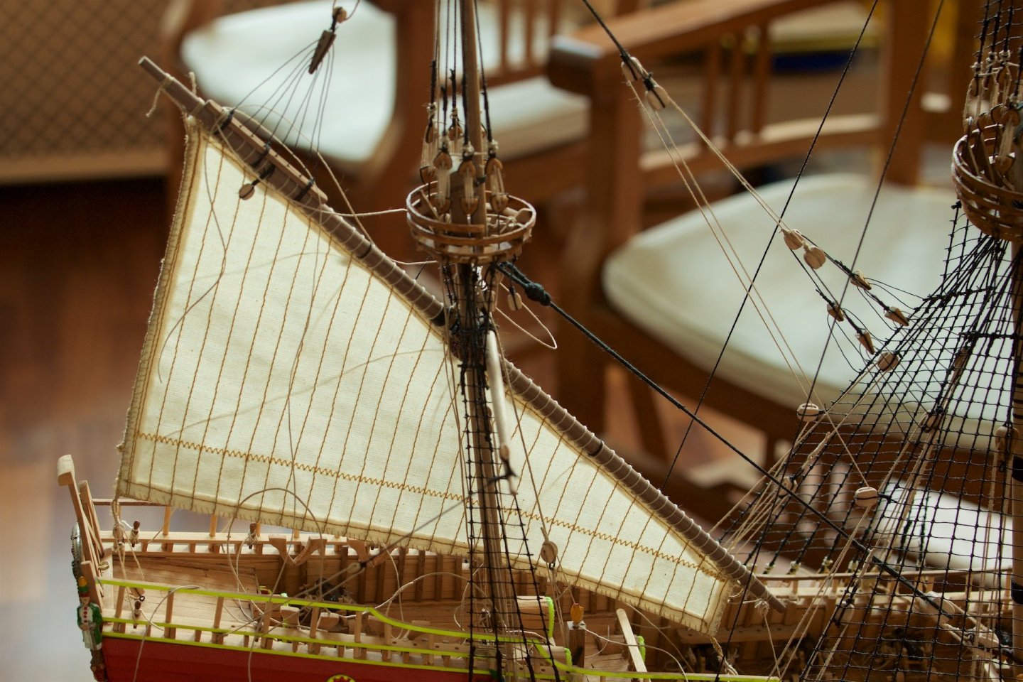
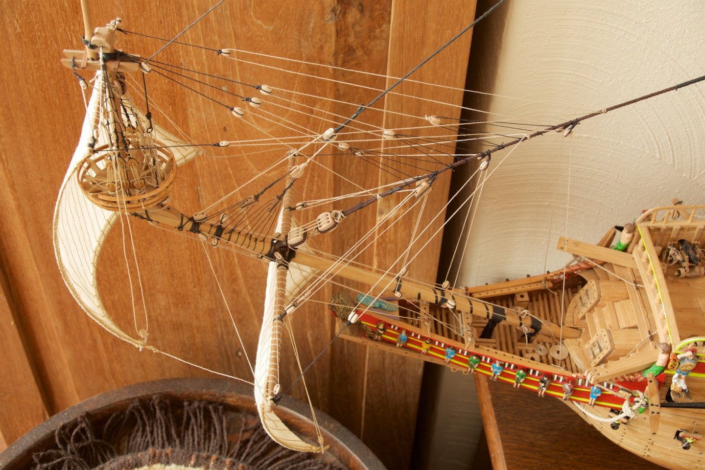
And also the second sail of the bowsprit installed, including the many ropes attached. It turned out that putting tension on the ropes from the yards towards the tip of the bowsprit was key in having this yard firmly in place. Surprising how stable this is now, with all the ropes at tension. Before attaching the ropes to the belaying pins, I had first watched on youtube how this is done on a real sailing boat. I attached the rope in this same 'real-life' manner. Only the ropes at the bottom of this lower sail towards the hull of the ship (the sheet line) is still to be done. Also to be done is making coils on the belaying pins.

-
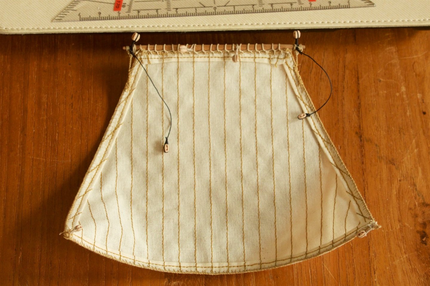
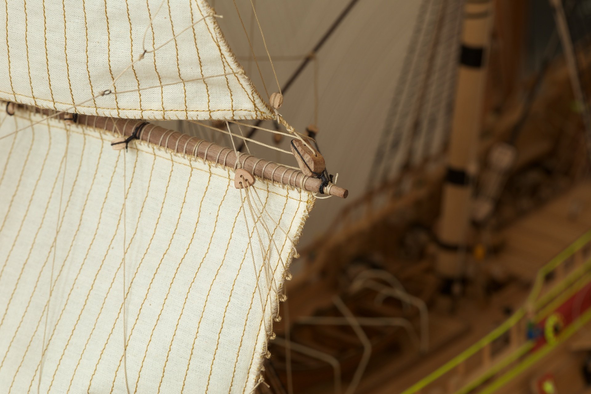
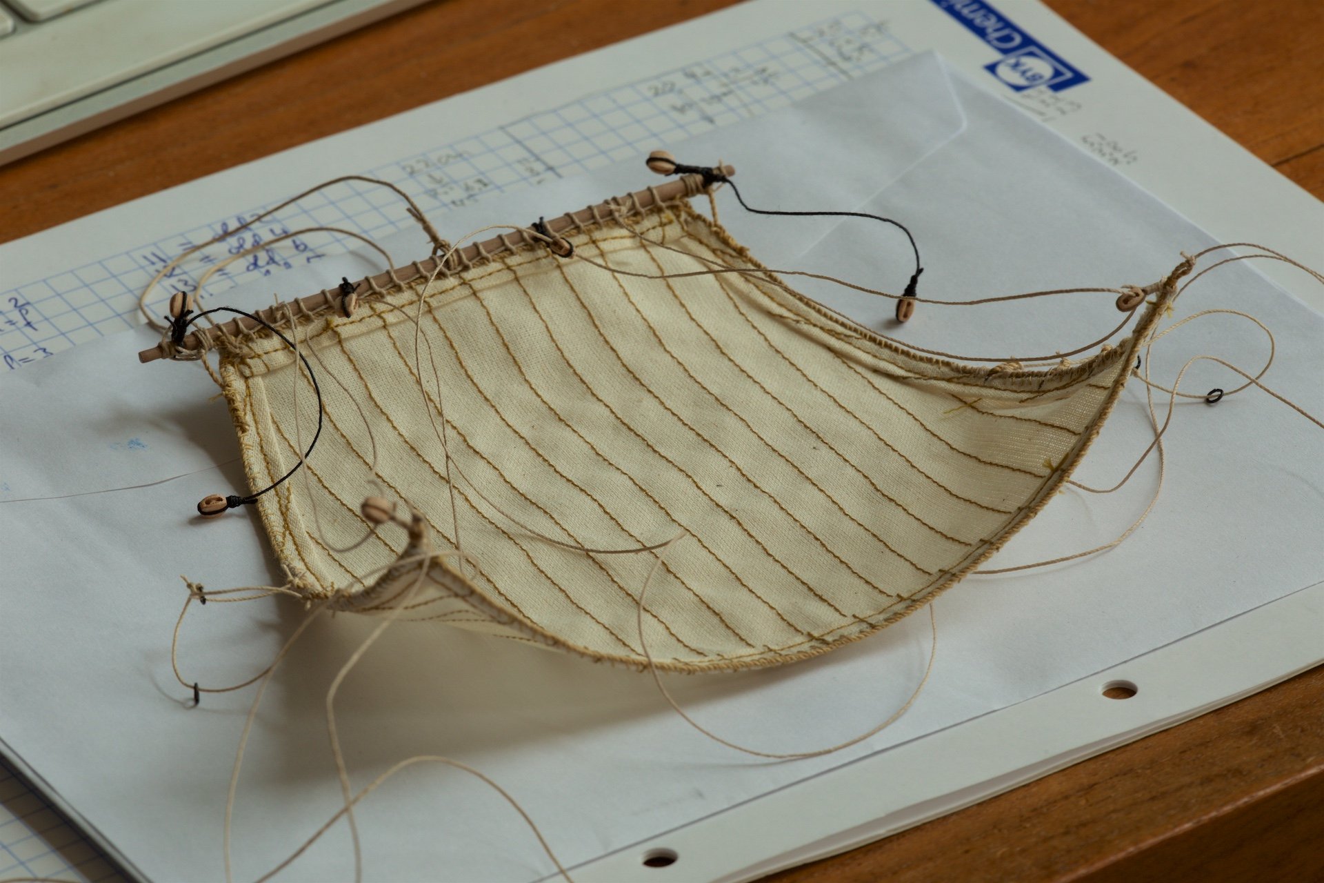
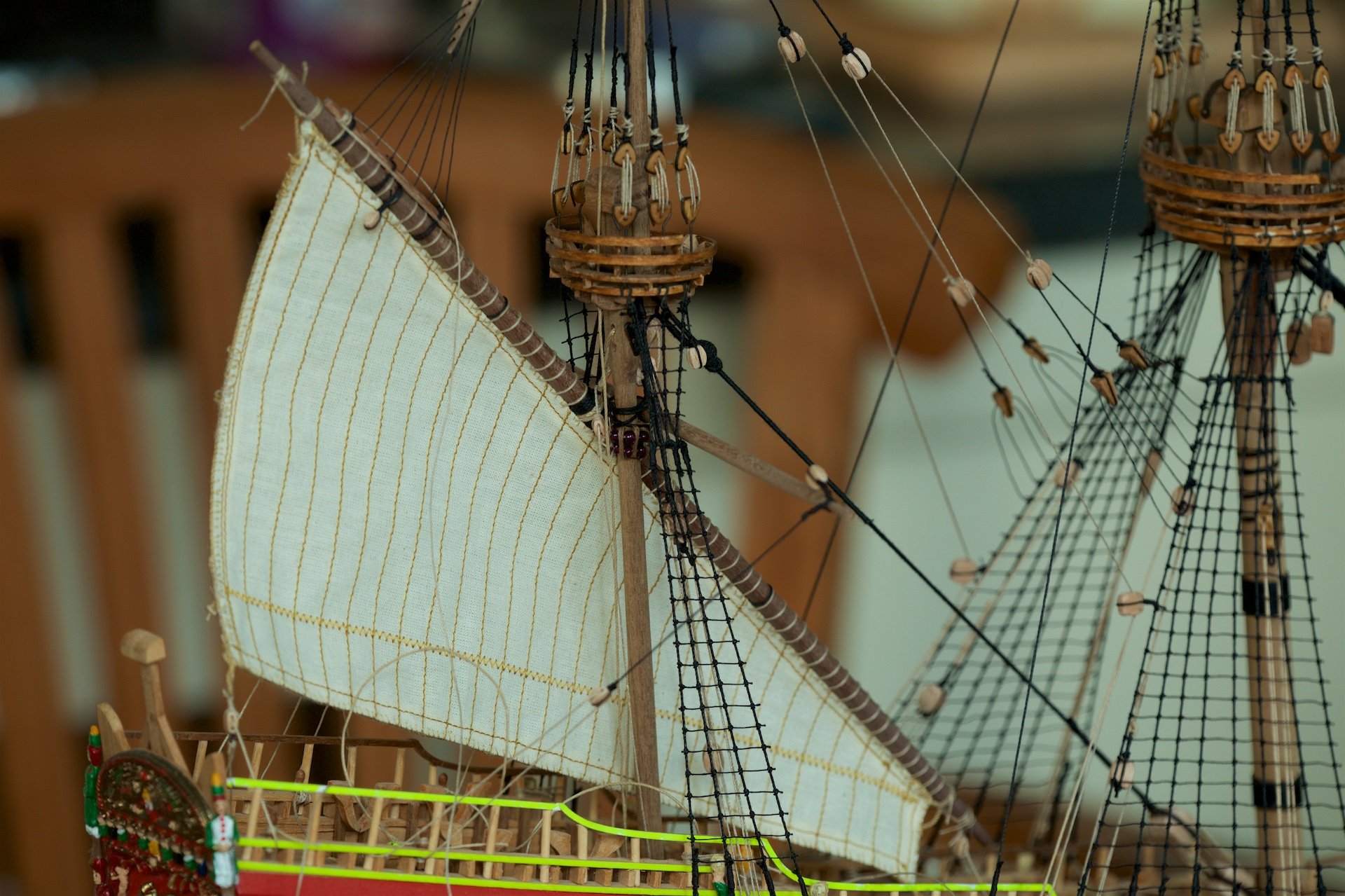
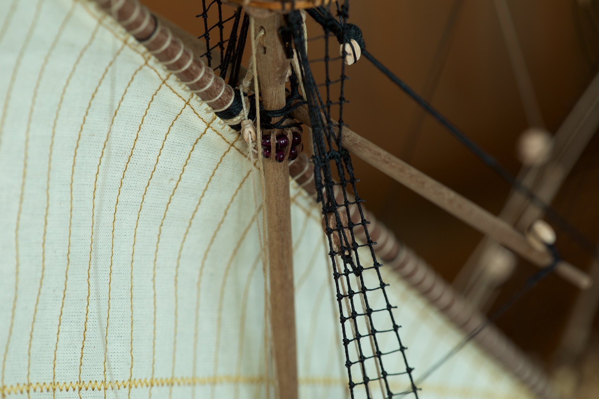
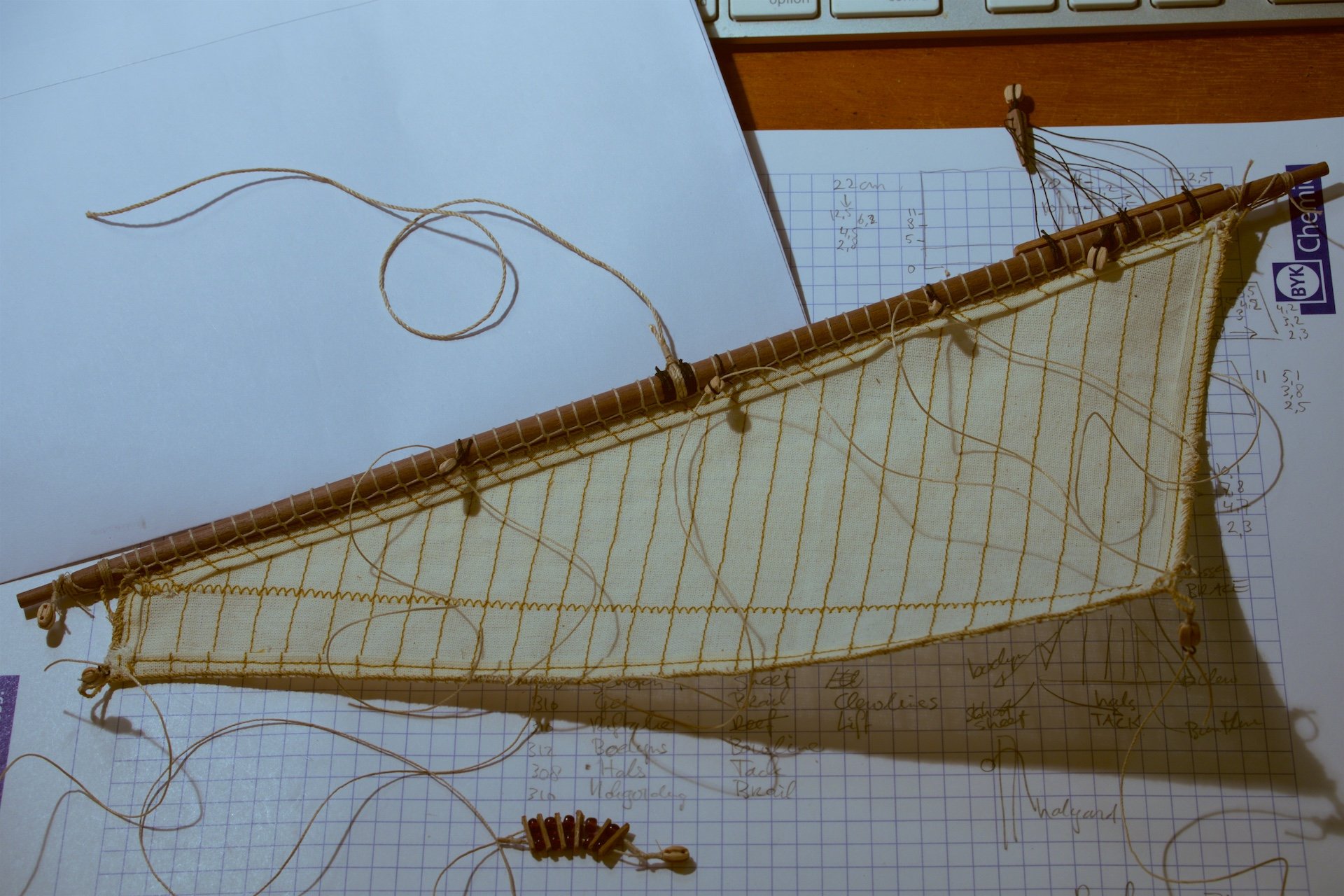
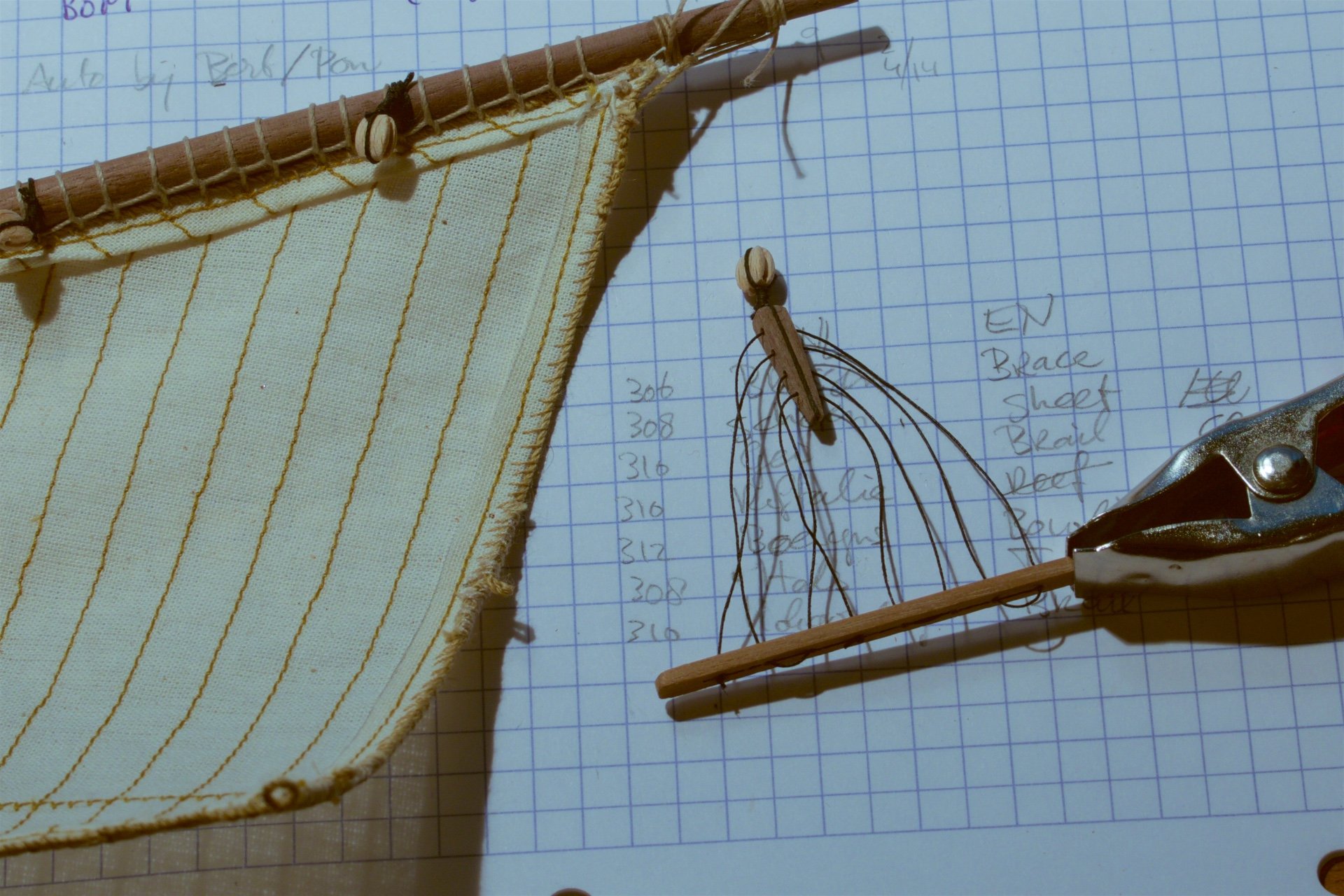
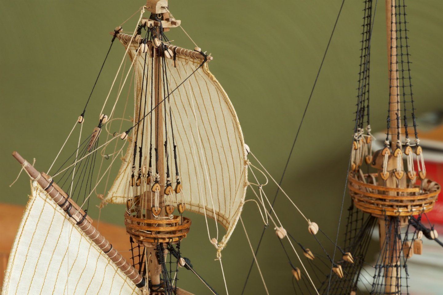
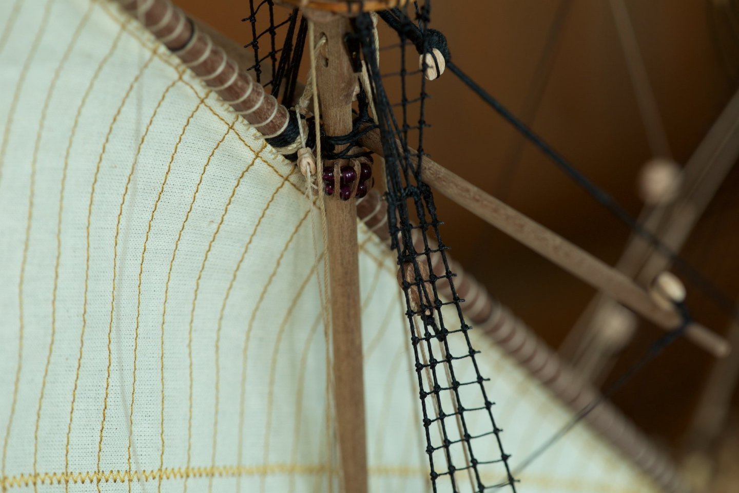
I have installed the first sail. Before installing on the ship itself, I had attached the sails to the yard and also some of the blocks. I have started with the topsail of the bowsprit. This area includes a lot of lines and thus a lot of checking for the appropiate connections of ropes and blockes and belaying pins. I had made the parrel from wooden strips and some brown plastic beads. The wires inside the seams of the sail make that it falls nicely and with some curve.