HOLIDAY DONATION DRIVE - SUPPORT MSW - DO YOUR PART TO KEEP THIS GREAT FORUM GOING! (Only 20 donations so far - C'mon guys!)
×
Andre
-
Posts
152 -
Joined
-
Last visited
Content Type
Profiles
Forums
Gallery
Events
Everything posted by Andre
-
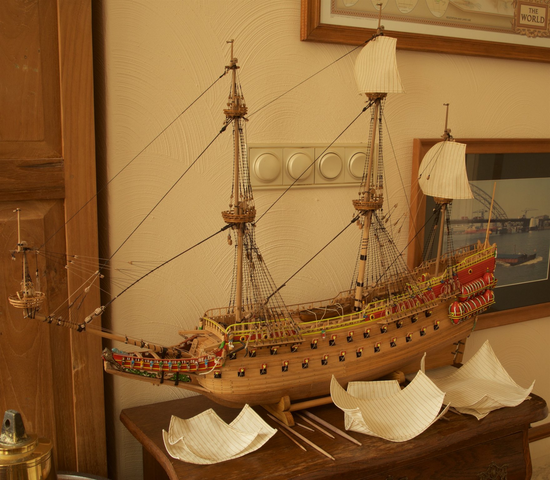
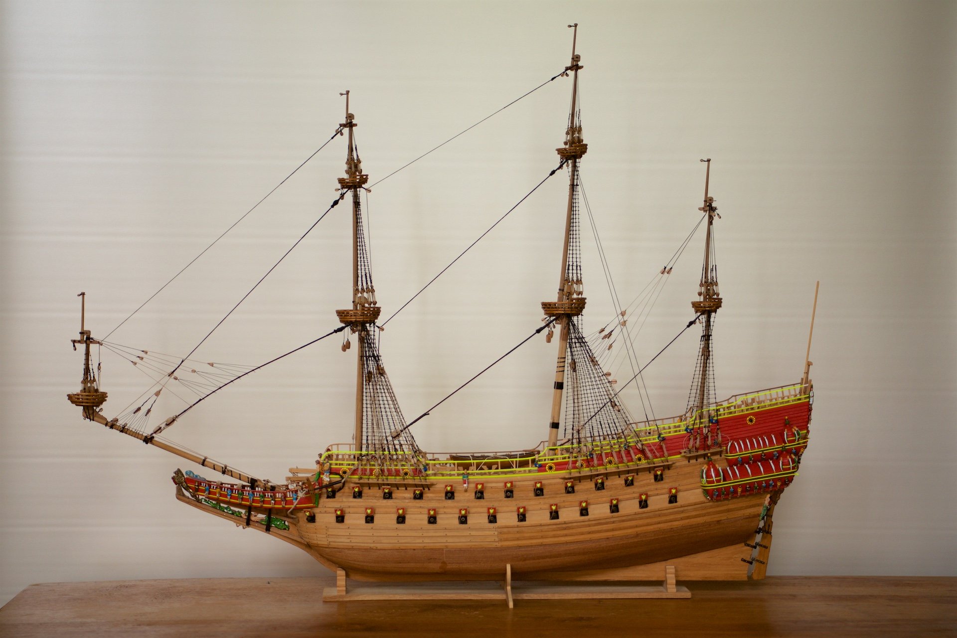
 Next step in making the sails was attaching the bolt-ropes, including the eyes at the corners of the sails. The eyes at the top of the sails, made by sewing the 'left-over' part to the sail. Originally, this should be done by splicing, but this was too difficult for me. A time-consuming part, because it was all handwork, whereas the previous step of the sails was with the sewing machine... The lower sail of the main mast does not have the shaping wires in the seams, because I intend to have this one furled up, like the 1:10 model in the Vasa Museum.
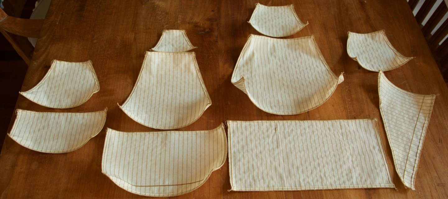
-
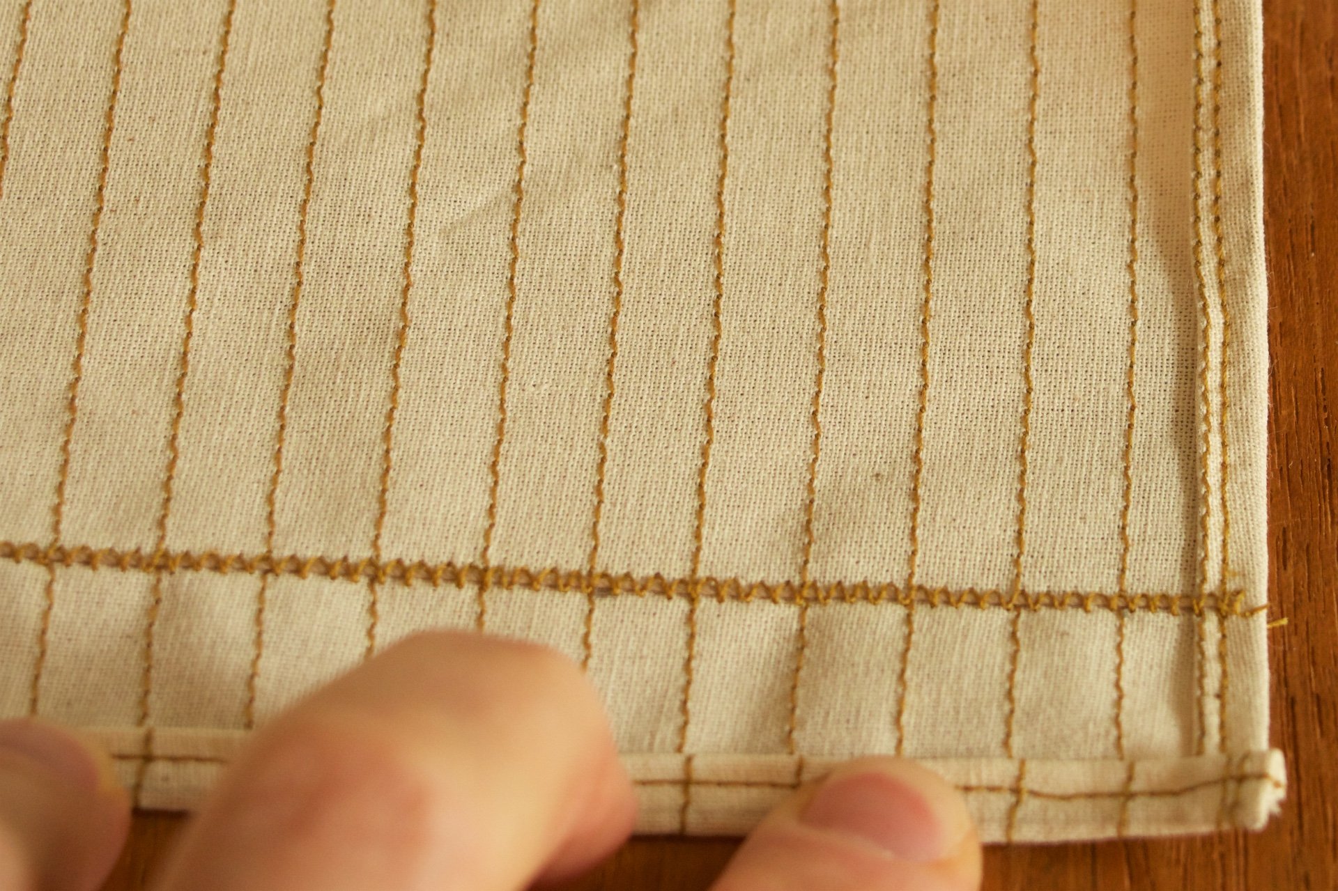
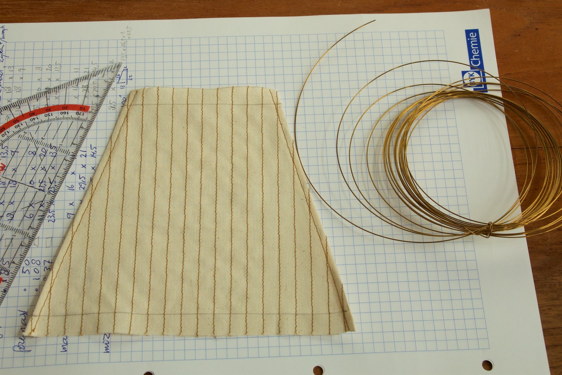
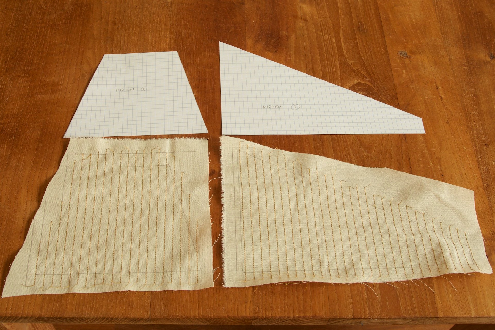
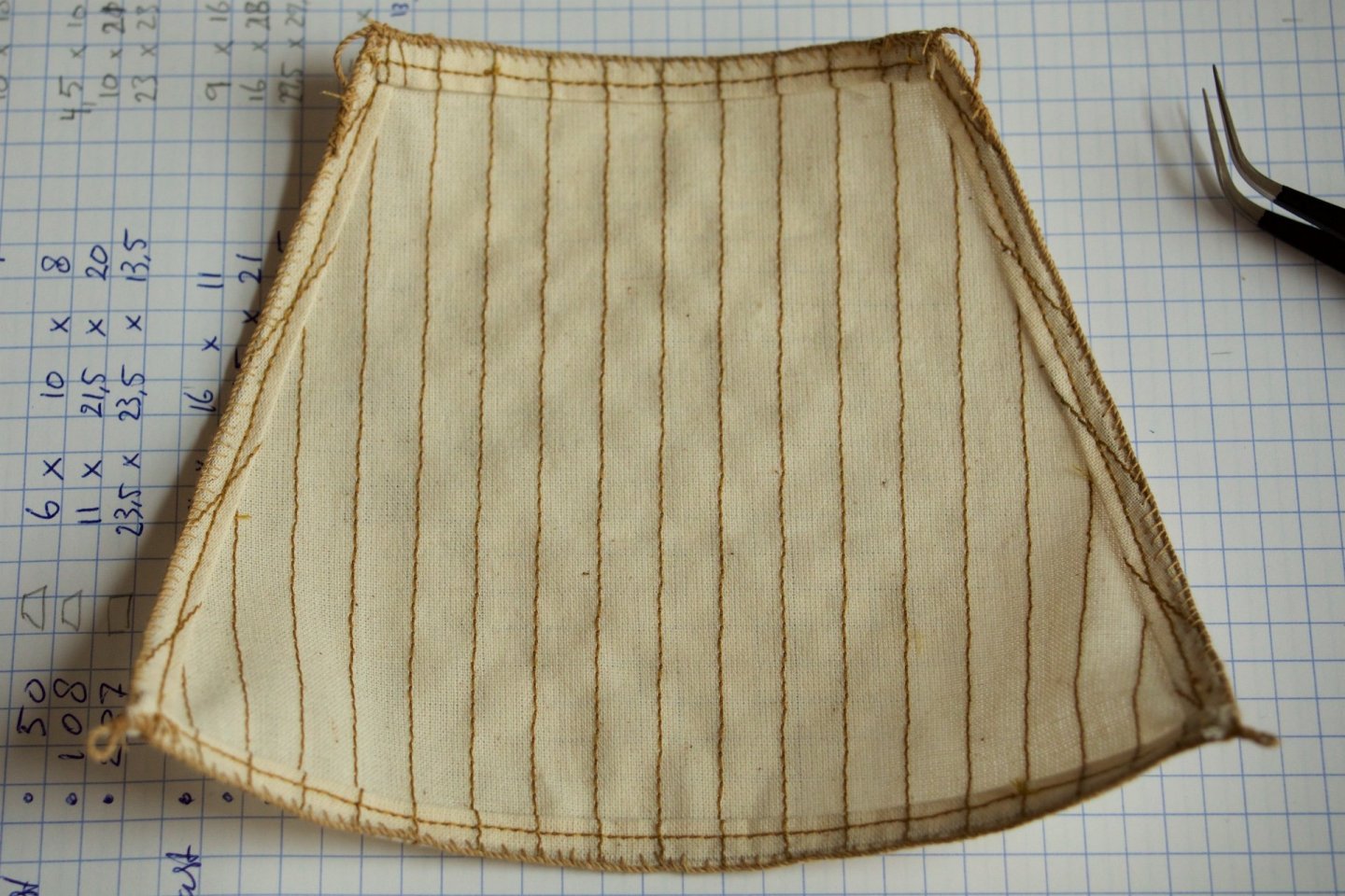
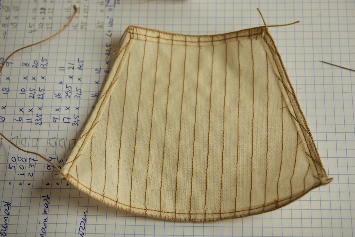
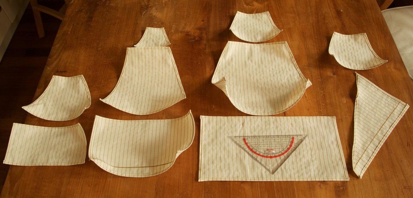
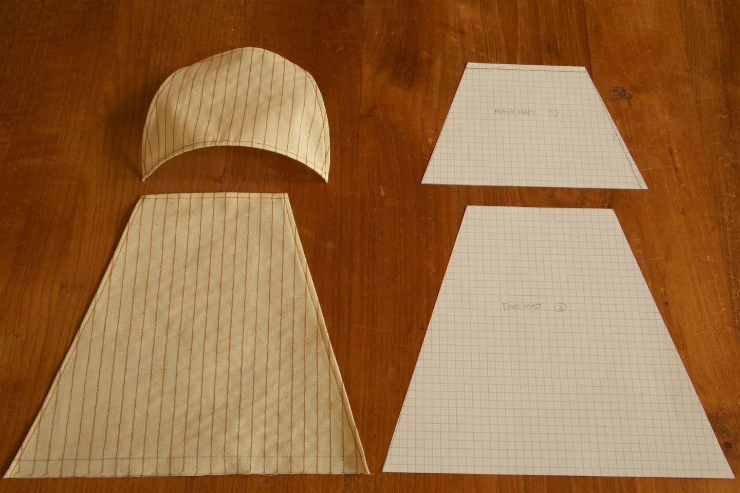
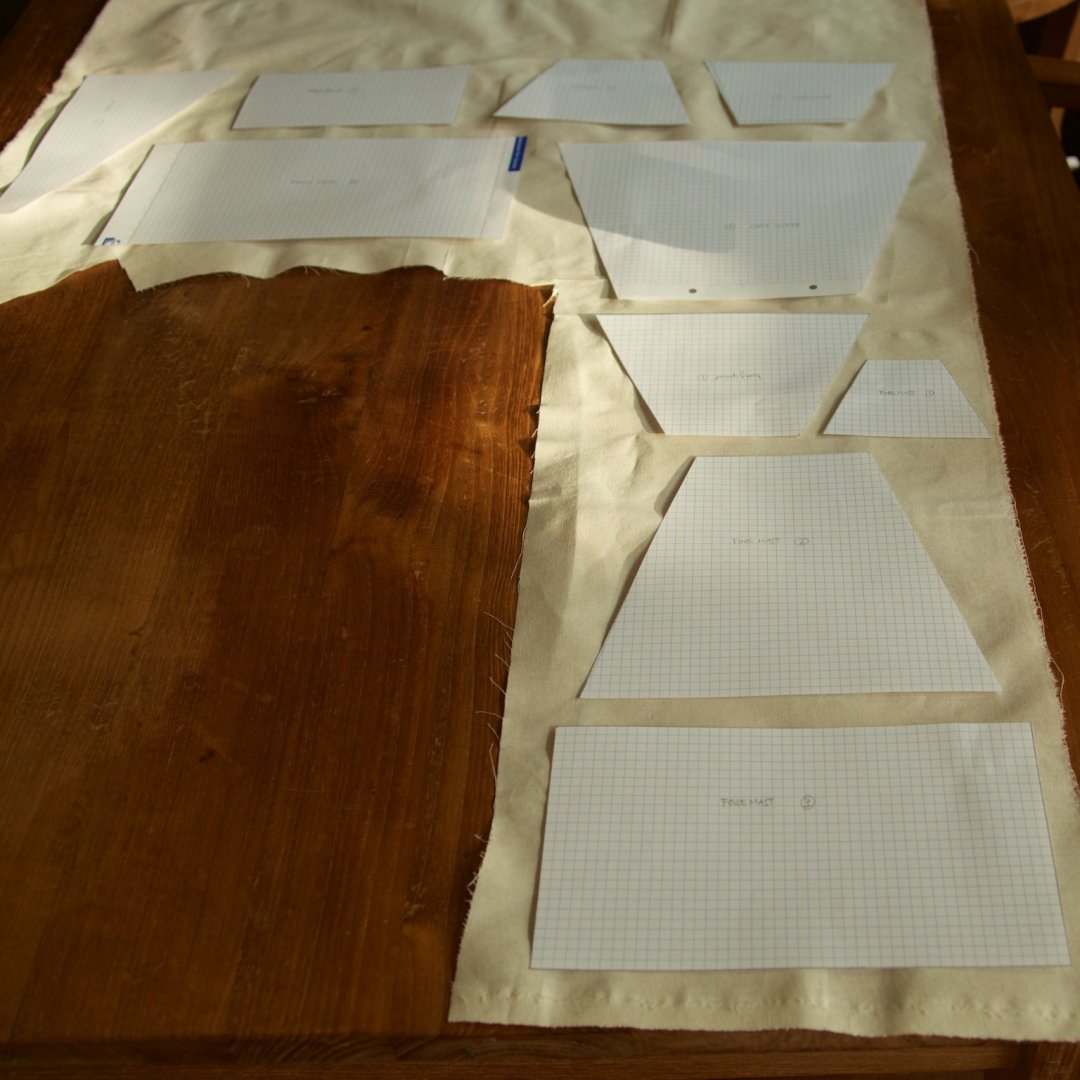
I have made good progress with the sails. Karl (Karleop) and Michael (Md1400cs) were a good source of information and example, as always. Karl had in his blog on MSW the dimensions for the sails for the Vasa, which I only had to modestly adjust to fit the sails to the dimensions of my yards. I have stitched the vertical lines at always 8 mm, because this was a convenient separation on the sewing machine. And the number of columns then fits nicely with the examples of others. After stitching the lines, I used a 1 cm overlap, that I divided in half to make the nice seams at the outside of the sails, I used an iron for shaping these seams. Before making the seam at the bottom of the sails, I inserted 0.5 mm copper wire in the seams. This will give a good and uniform bended shapre to the sails lateron. I also inserted the wire in the bottom seam. The copper wire was already bent. With the wires inserted, some of the sails can be mounted losely even without the yards... As I had seen done by others, I had added the reinforcing rope at the lower sail of the foremast.


-
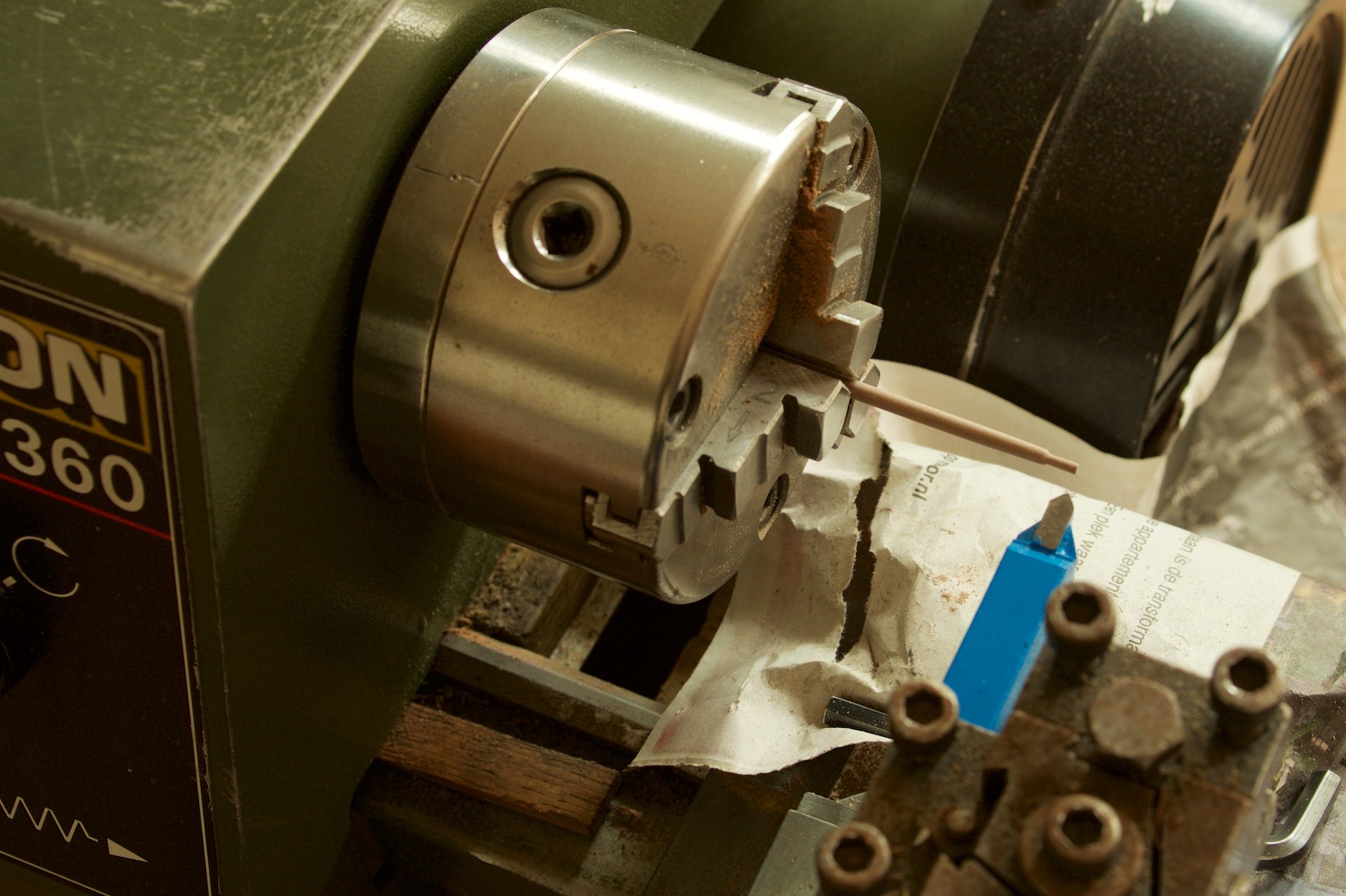
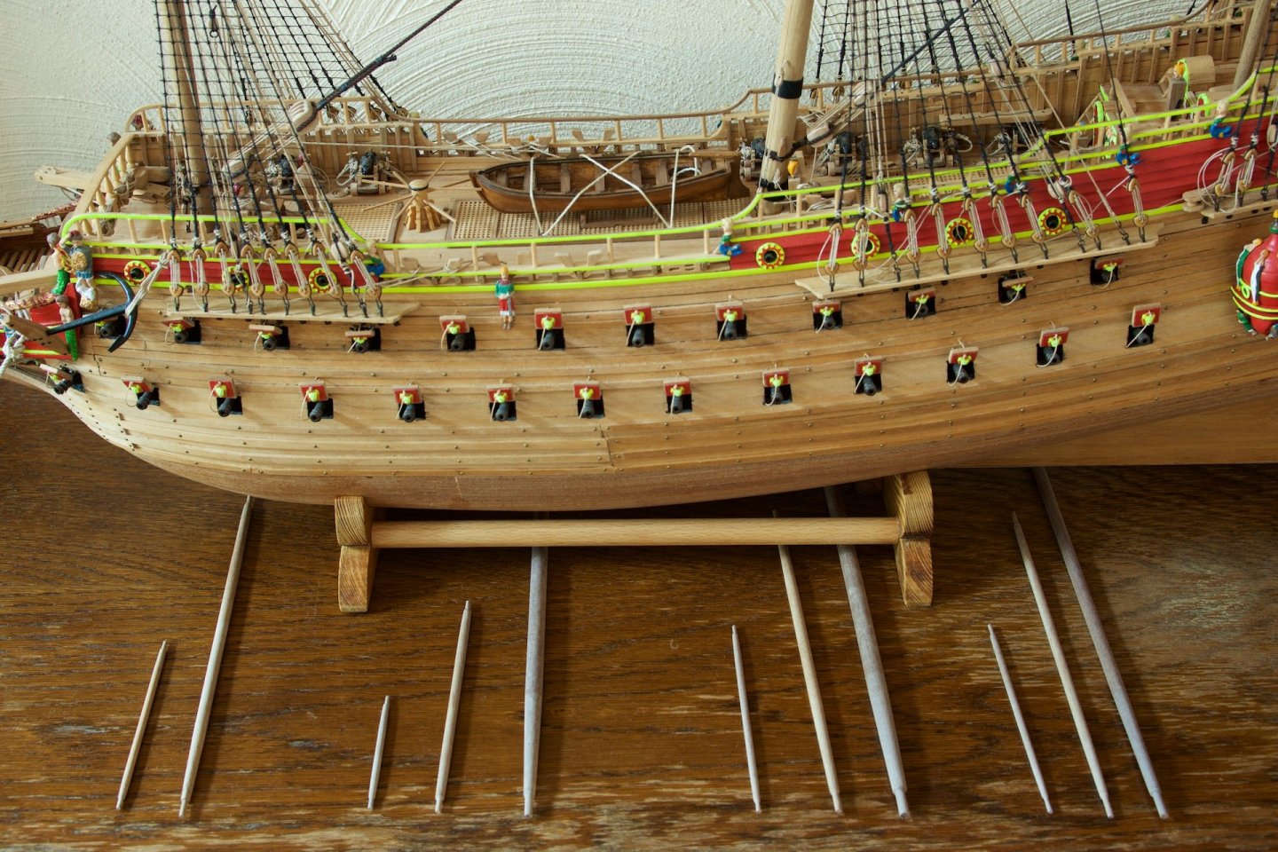
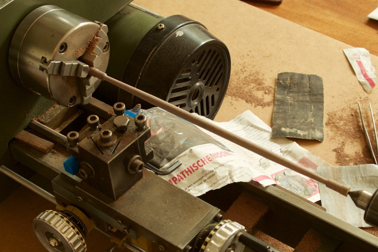
I have made the yards, following the dimensions as described in the Corel instructions. I have done the tapering with my larger lathe (I had bought a very old version). This is a bit overkill compared to the smaller lathe, but it has the big advantage that this lathe is more intended for metal turning. Therefore, the knives can be fixed into a holder and the wood turning is thus more precise, as I could now do the tapering with a fixed angle of about 3 degrees. The big yard on the foremast took most time, because it is diameter of 7 mm, whereas I did not have nutwood in that diameter, so I made it from 8 mm.

-
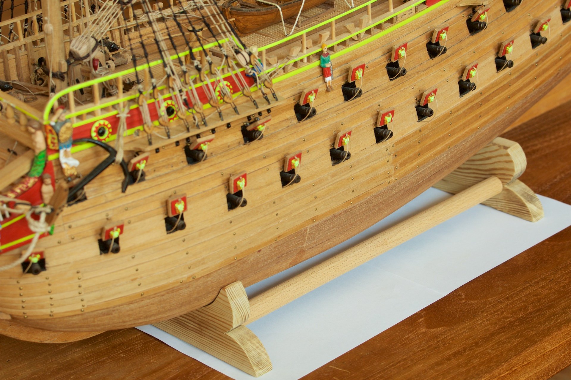
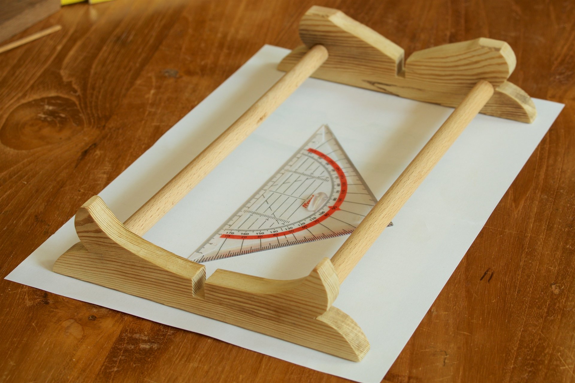
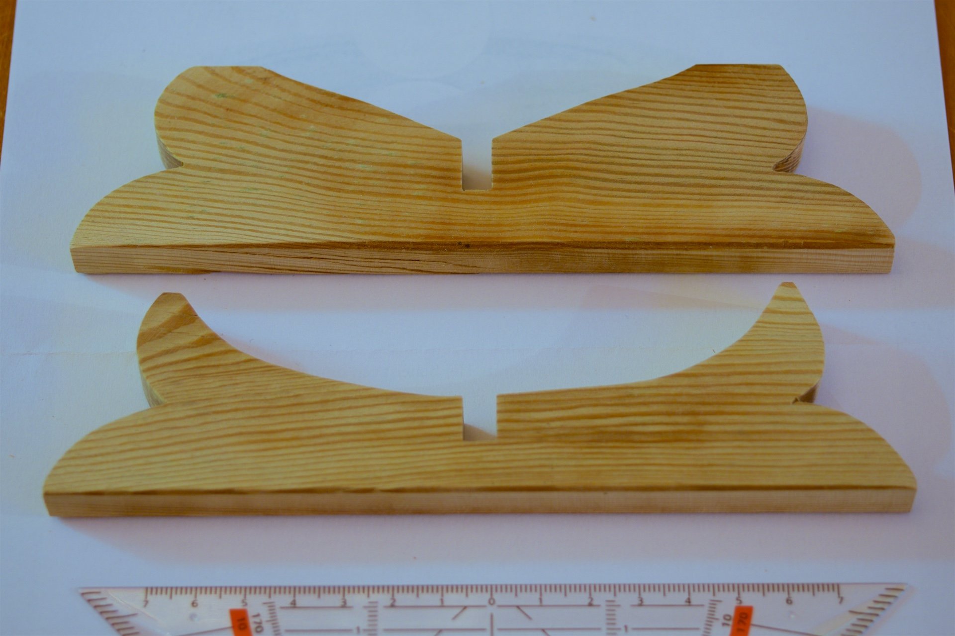
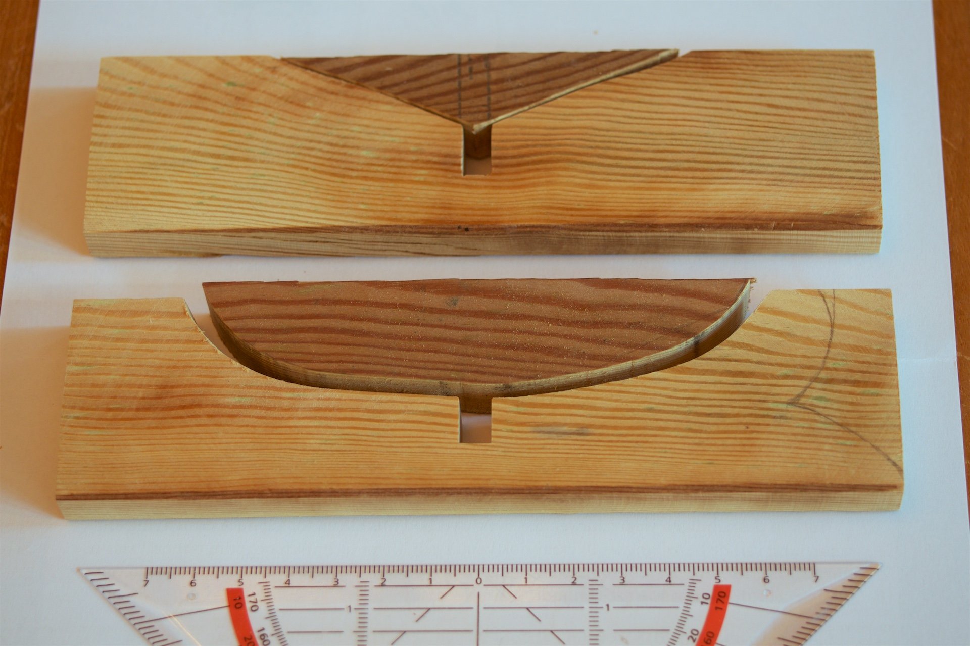
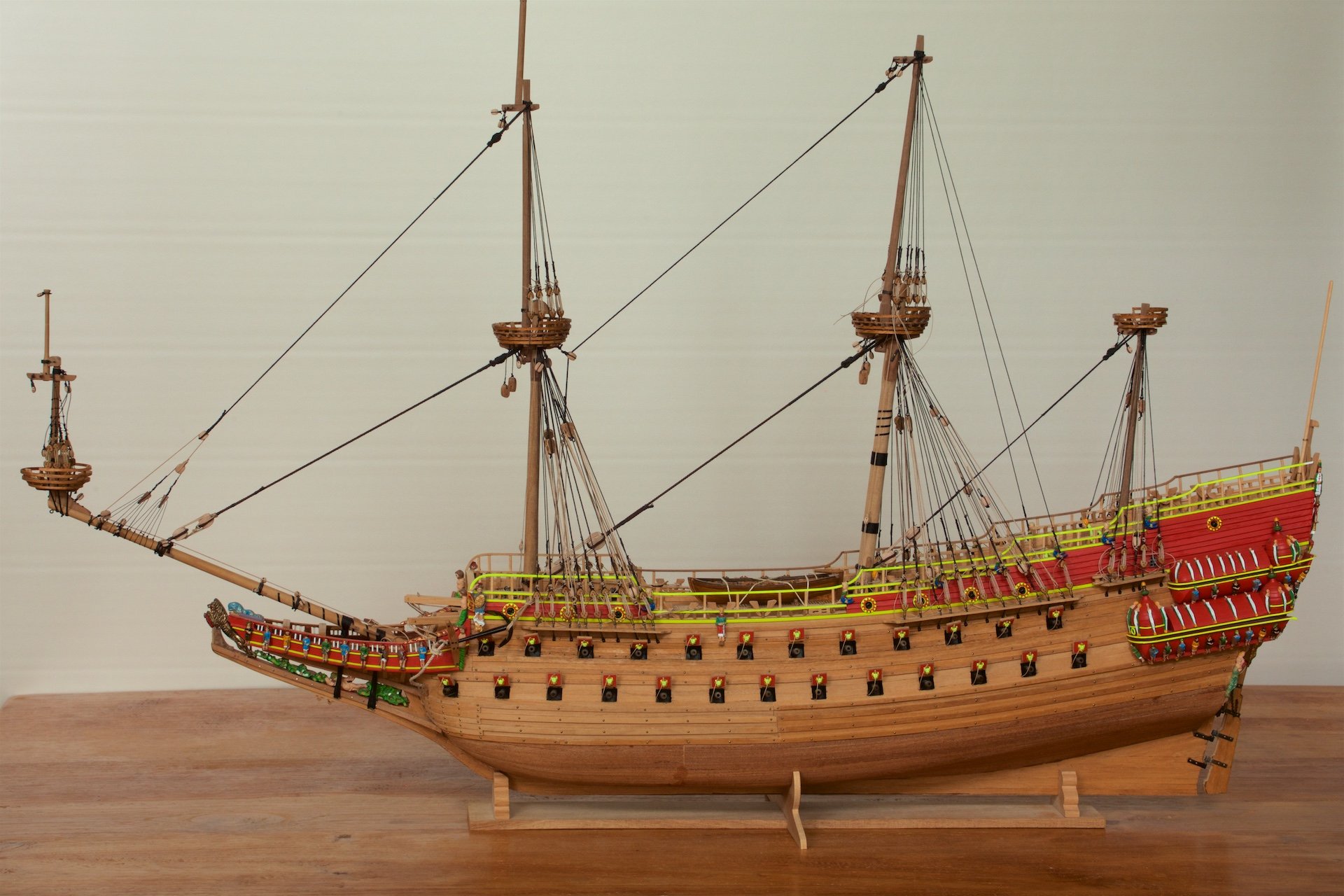
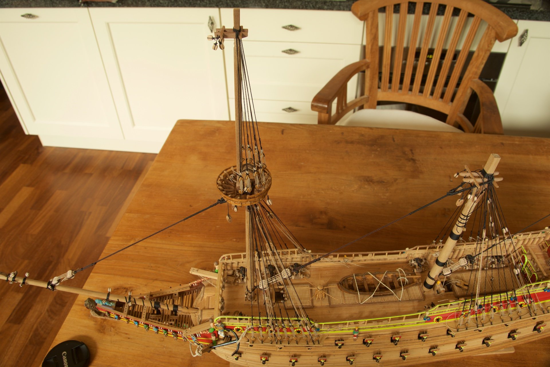
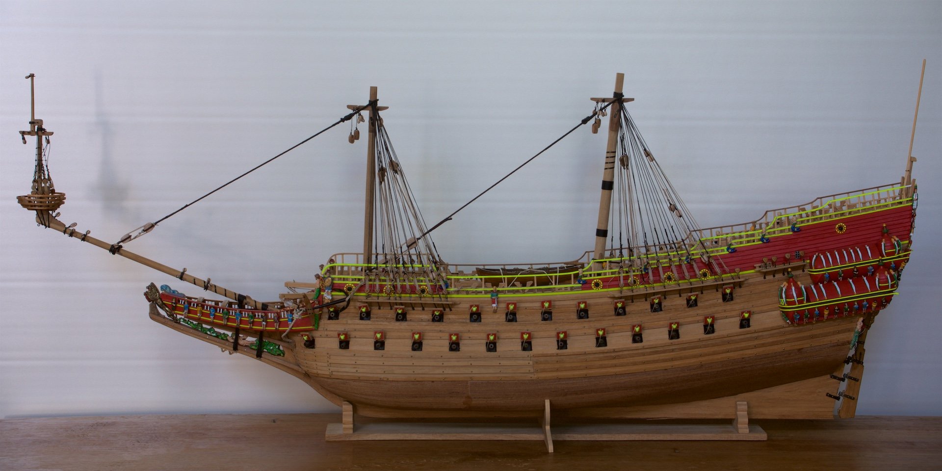
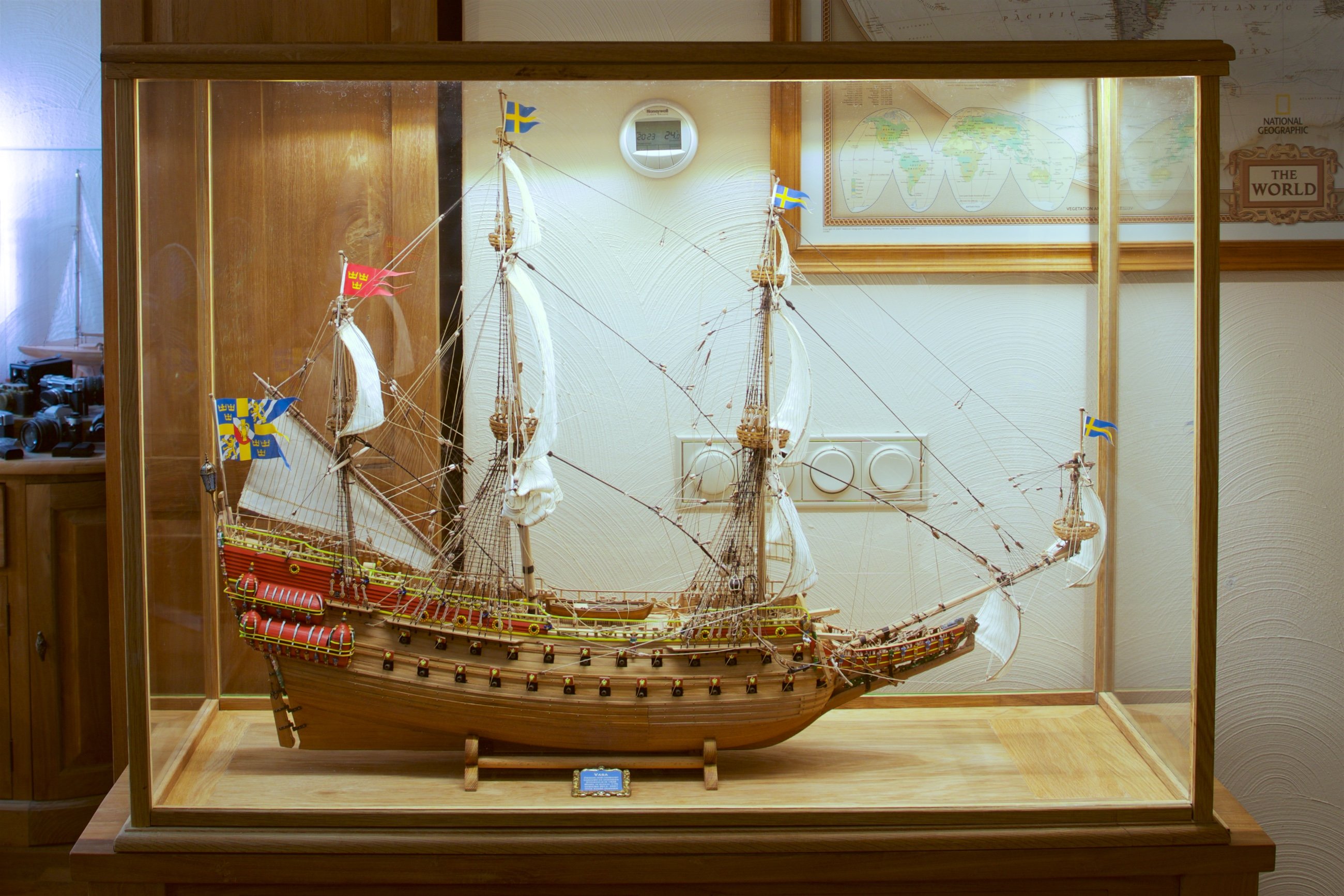
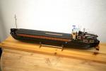
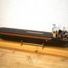
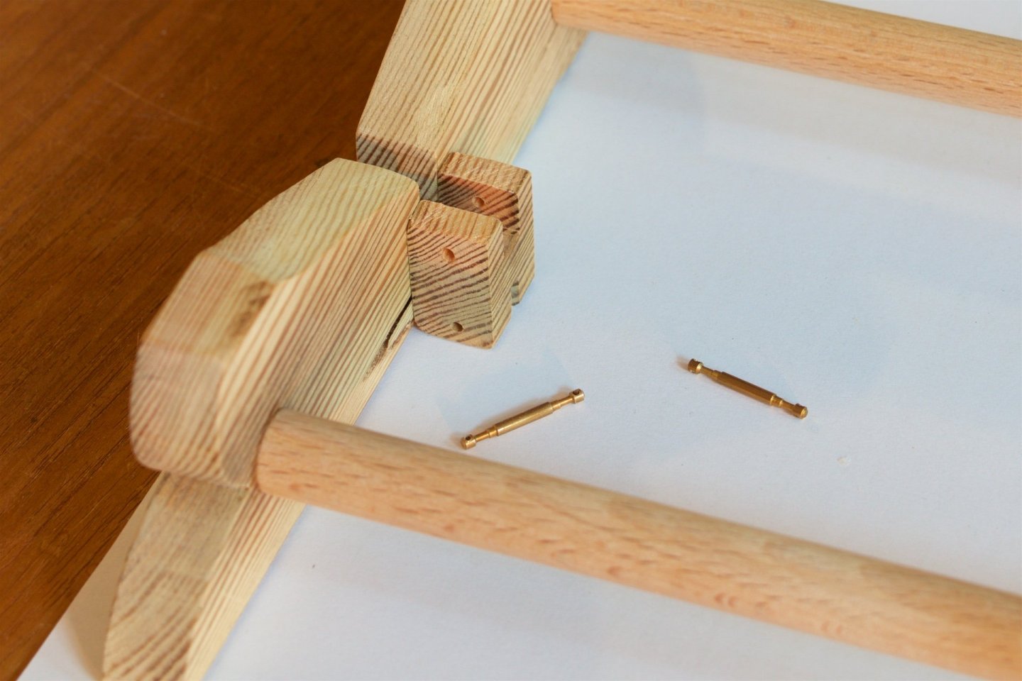
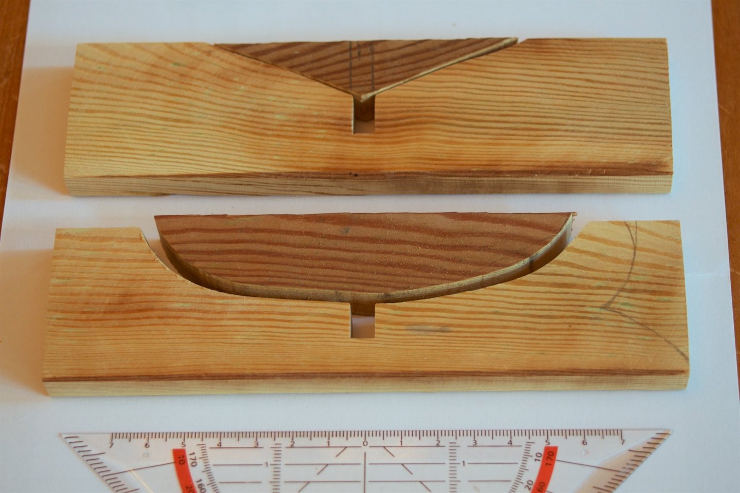
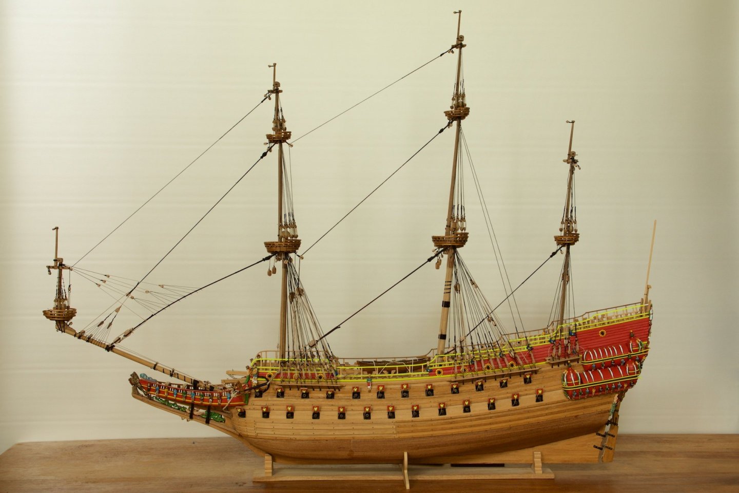
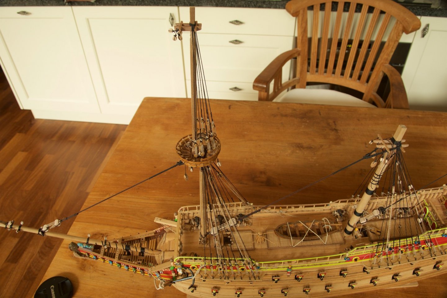
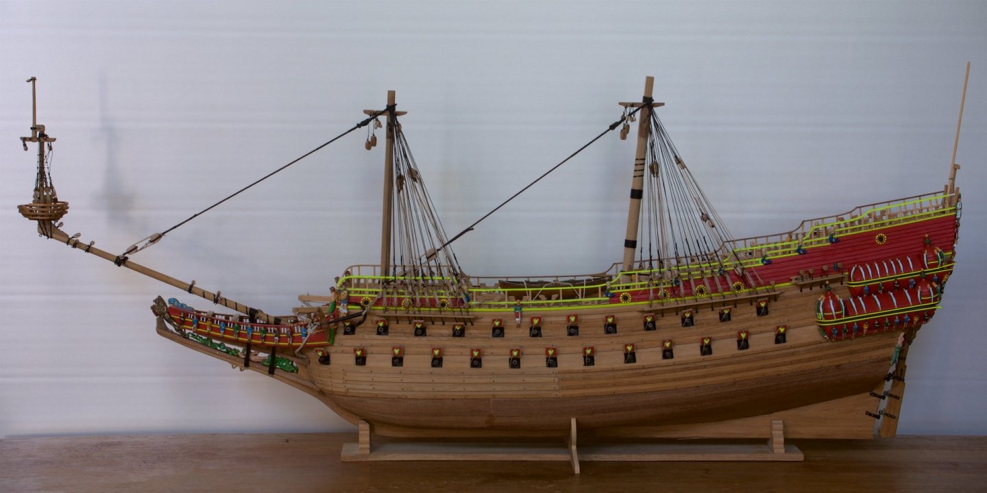
With the masts in place, I noticed that the stand that was provided with the kit is not very stable, because the center of gravity is now higher with the mass of the masts. Therefore, I decided to make a new stand. I had some old solid wood that I had kept which was dark with some wood stain, but with sanding it became light colored again. I had cut some paper to match approximately the shape of the hull at the places where I wanted to have the hull resting on the stand. I made the shapes in the wood using a band saw, followed by more detailed sanding to fit the shape. In order to have the stand and the ship attached for the cases that I want to place it somewhere else, I have added some additional wood blocks in between and these wood blocks are equipped with two holes: one to fit a rod in to fix it to the hull/keel of the ship and the lower holes are prepared so that the stand can be fixated into a display cabinet, lateron. It was quite some effort to align the holes in the stand with matching holes in the keel...


-
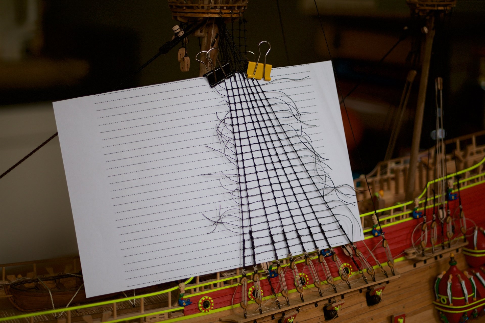
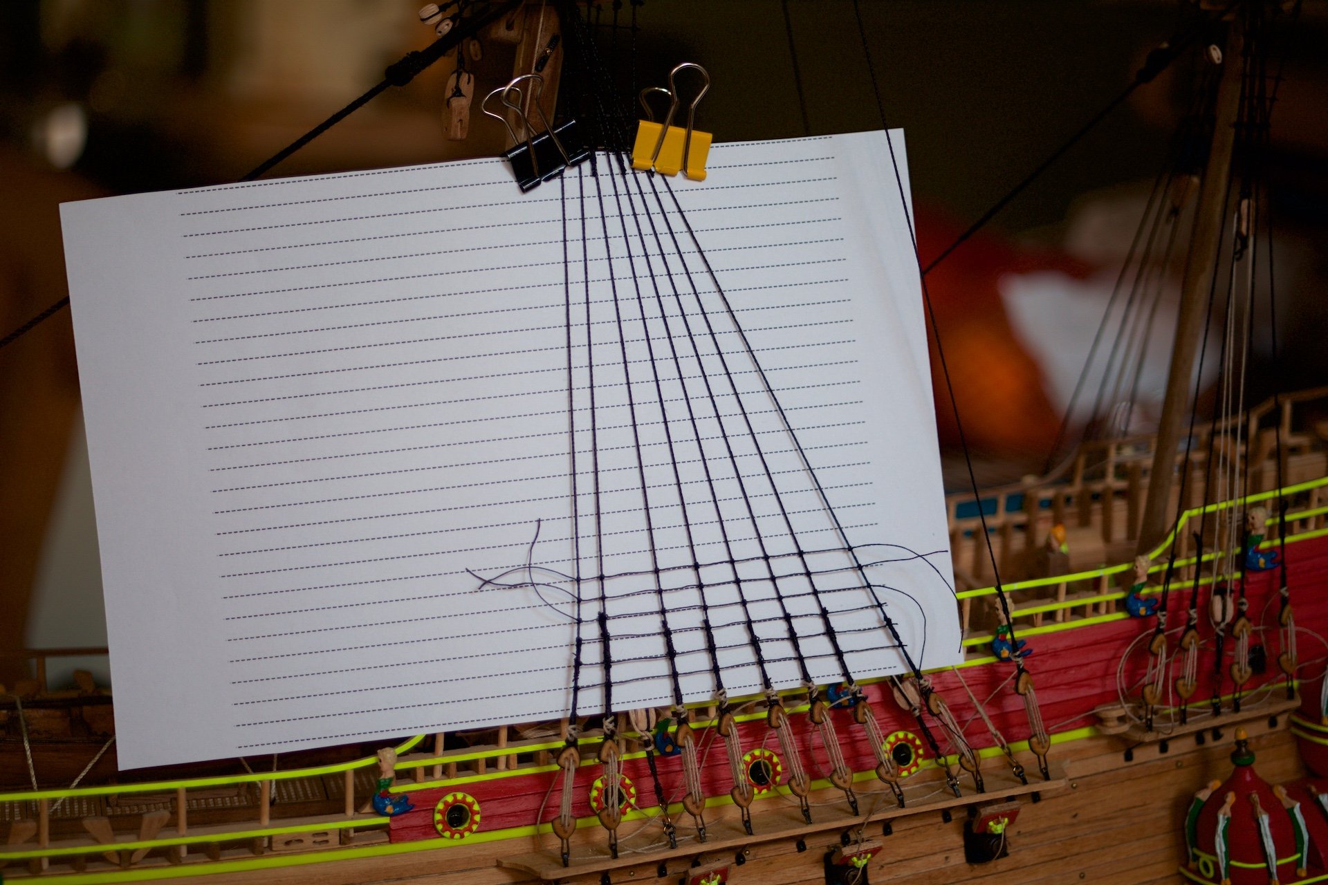
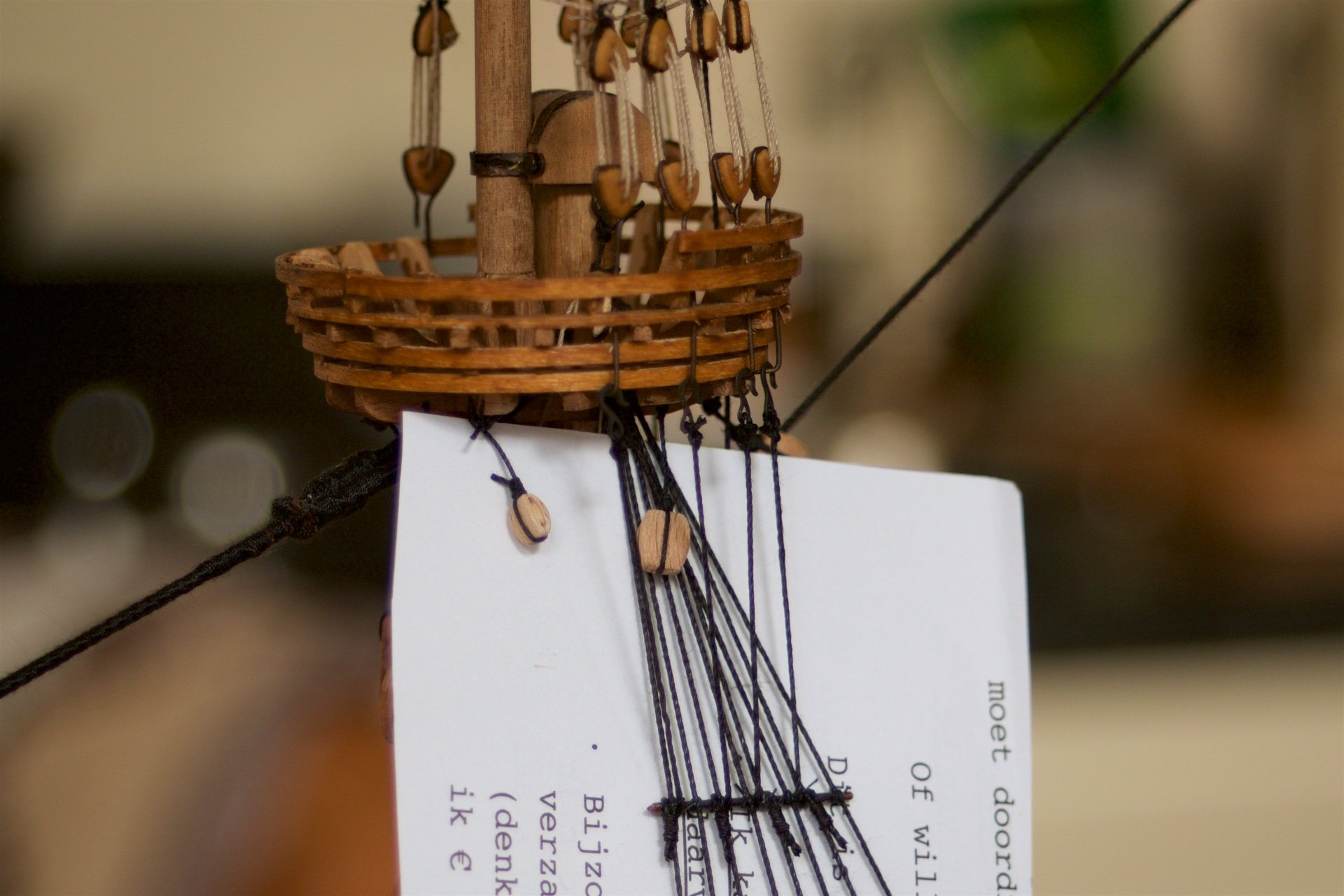
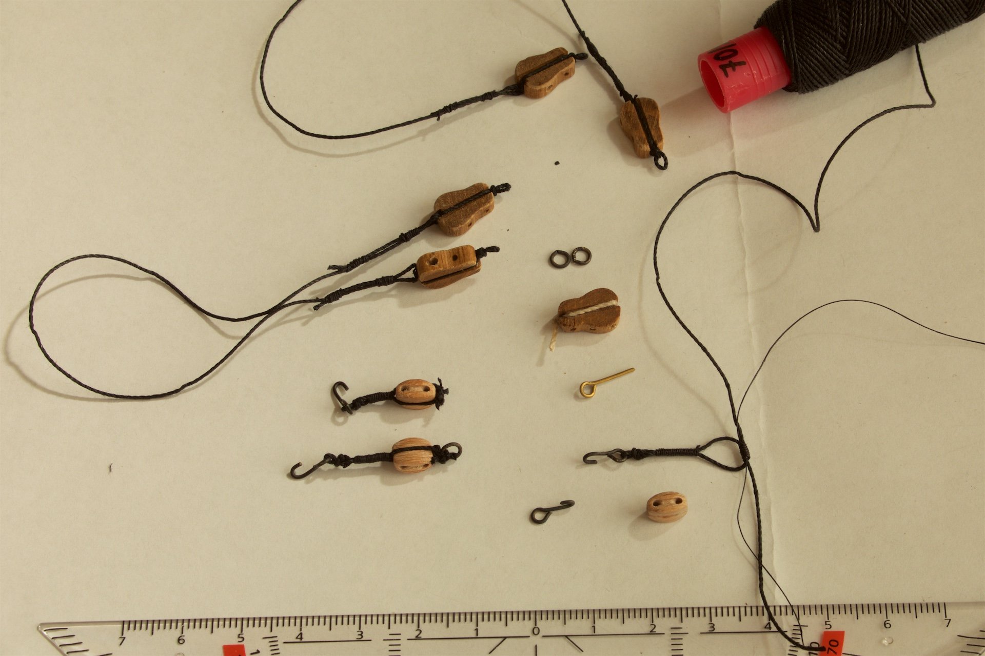
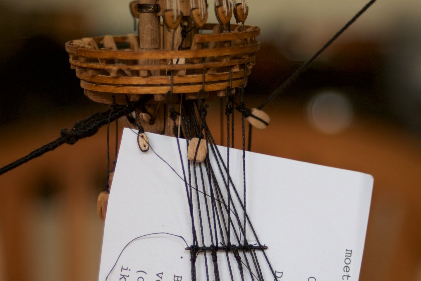
Following on the futtock shrouds, I had first made the ratlines for the futtock shrouds. This also to get some experience with making and tying the rat lines. Next step was of course making the ratlines for the normal shrouds. Naturally, this took many hours. Prior, I had thought that making the ratlines would be unpleasent, but I rather enjoyed it. In order to have equal distance between the ratlines, I had printed (from Excel) equidistant lines of 5 mm on paper. The paper then attached behind the shrouds, which made it also easier to see the ropes and to push them around the shrouds. I made ratlines only on the shrouds leading to a platform, so not at the upper parts of the masts. In the book of Zy Mondfeld, it is described that these sections should not have ratlines, and I also saw that in the museum model these upper shrouds are without ratlines. Meanwhile, I also made the stays from the toplevel of the mizzenmast to the shrouds of the main mast. This was again with self-made 'triangel' blocks.


-
I am now busy with the futtock shrouds. I have first attached a copper rod (1 mm diameter) beneath all platforms, such that the futtock shrouds are approximately vertical. I had first patinized the copper rods. I knotted each shroud to the rods, using a rolling hitch. The futtock shrouds are then attached with a hook to the metal rods from the deadeyes connections beneath the platforms. I used a buntline hitch to attach the ropes to the hooks.

-
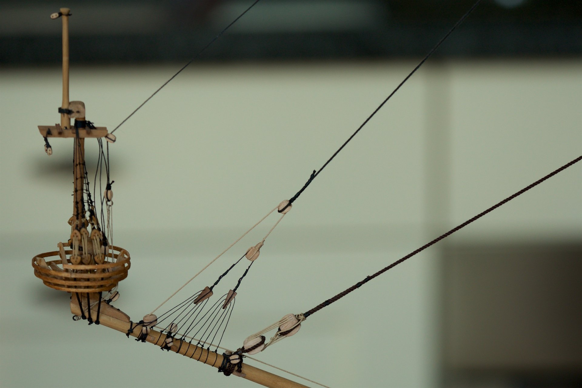
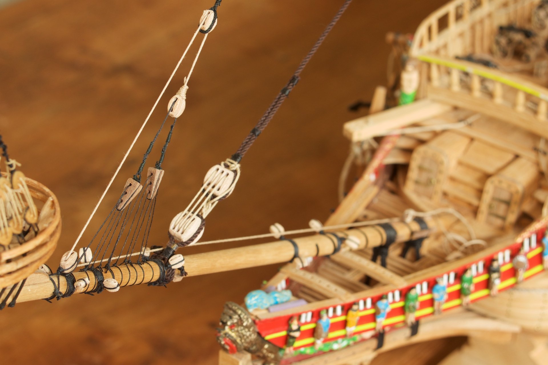
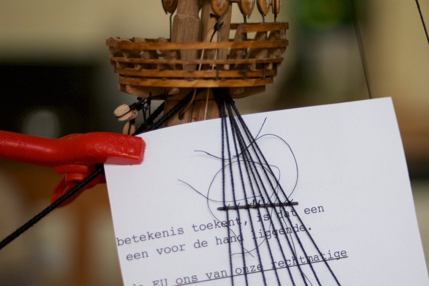
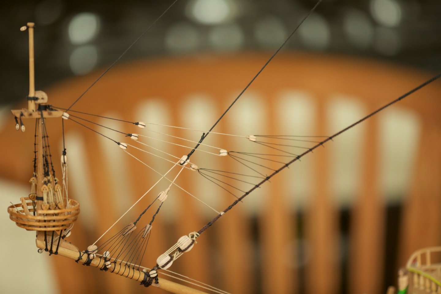
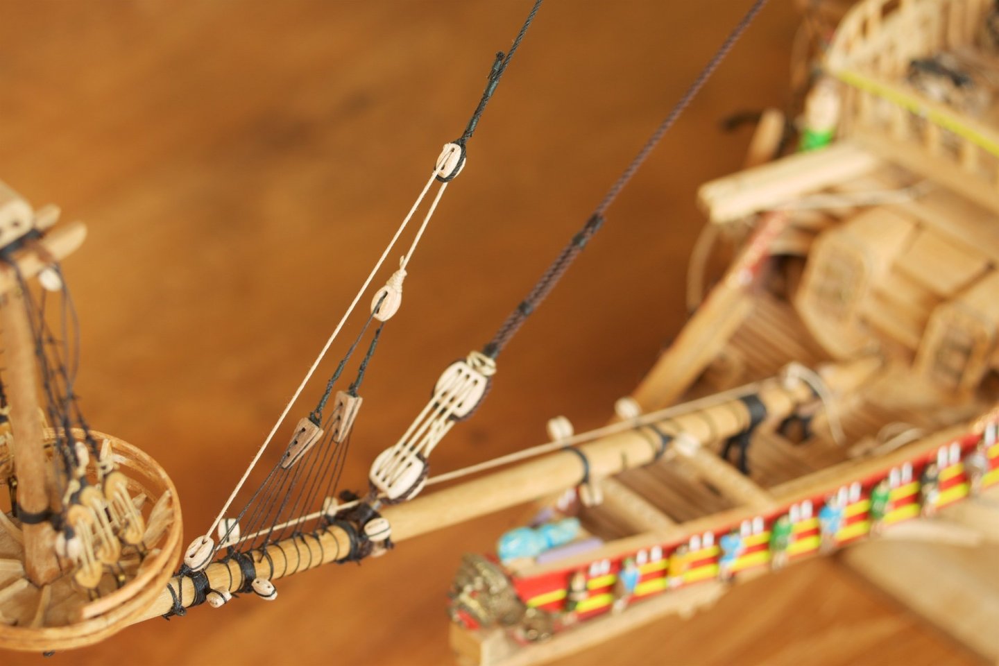
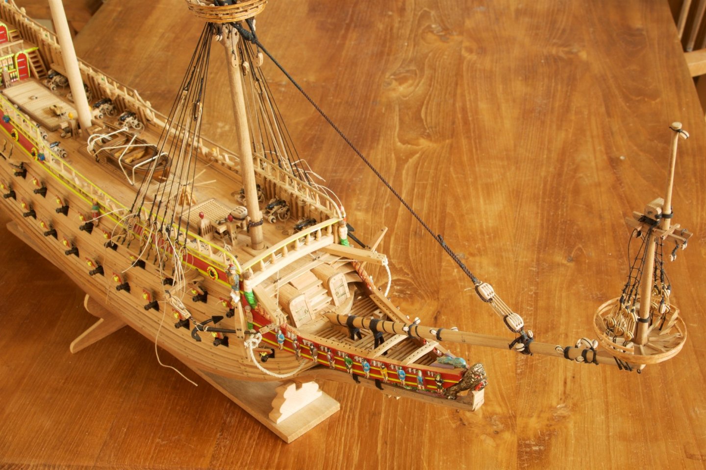
I have now reached the maximum height of the model, because I have now also installed the two remaining top sections. At the bowsprit section, I have now also made the stays from the bowsprit mast to the forestay. Before attached these 12 lines, I had first put some extra tension on the stay. With the stays higher on the foremast, there had been some loss of tension. With the additional 12 lines, the stay does curl upwards. I think this is difficult to avoid. I assume that this can be prevented by putting even more tension on the stay from the foremast to the bowsprit, but I also do not want to risk putting too much tension on the bowsprit itself... Balance - Balance... I have attached the 12 lines using the 'rolling hitch 2', Ashley knot number 1735.
- 206 replies
-
- 10
-

-
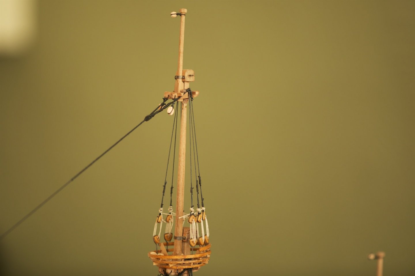
The building of the masts is nearing completion already. Meanwhile installed one royal mast: the fourth section, or uppermost part, of the foremast.
-
Hans, I am happy to read that you adhere to the same thoughts on the levelling of the platforms. I am also following your Dutch log on the 7P: wonderful !
-
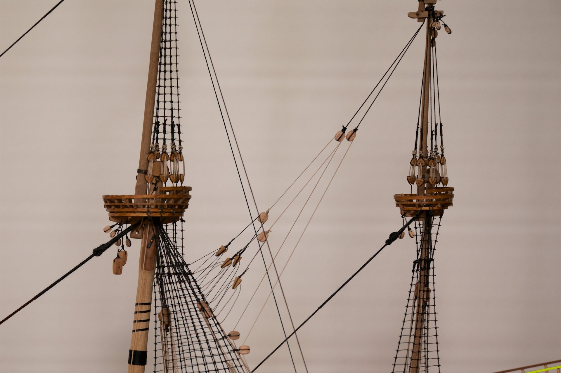
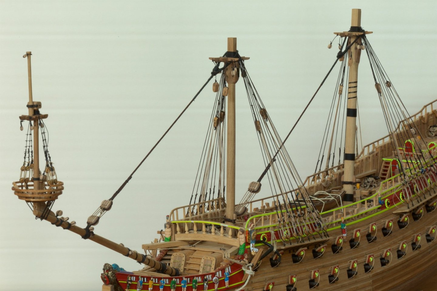
Meanwhile also made and installed the topmasts of the mizzenmast and the foremast. All drawings and other models show that the platforms of the mizzenmast and the main mast are tilted, but I find that odd to see. Therefore, I have them approximately horizontal. The last photo shows the three stays at the bowsprit, coming from the foremast. The lowest stay is 2 mm, the middle is 1.2 mm and the top is 0.7 mm. Mizzenmast: Foremast, with not all ropes cut yet:


-
First, I had corrected the rope from the stay on the block at the bowsprit. Meanwhile, also made the shrouds on the second part of the main mast. And the stay from this second level to the foremast. The number of deadeyes at the wales for the main mast is nine. I had seen in the technical discussions at the Vasa Museum that it was likely that the last/nineth deadeye was not for a shroud but for a back stay. So, I had decided to use this one for a backstay to the second level of the main mast. I used the same rope thickness as for the shrouds thusfar.


-
Michael, Patrick, Thank you for your compliments! Michael, I had not even noticed using the wrong side of the block. Is an easy fix :). Thanks for alerting.
-
Also the stay from the second level of the foremast to the bowsprit now made and attached. It was a tedious task to make sure that the two times three ropes were of correct length to ensure that there would be tension on all of them. The way it came out is not perfect, but good enough. It is nice to see that the tension on each of those 12 ropes is not that high, but the tension on the one rope for the stay is actually rather high. And next also to the second level of the main mast: installed the platform (previously already made), the deadeyes on it, and installed also the second mast. Again, like the fore mast, with a fid and a rope to hoist the second mast up and down. Again, the second mast is not fixed by glue.

- 206 replies
-
- 14
-
-
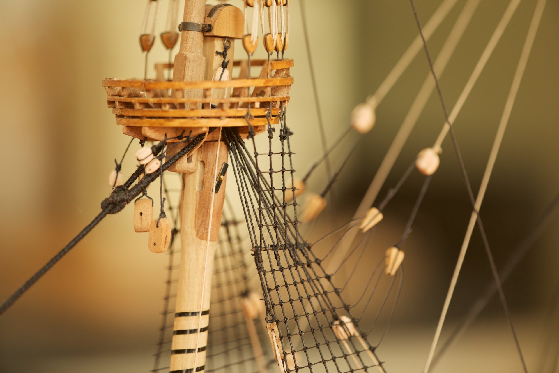
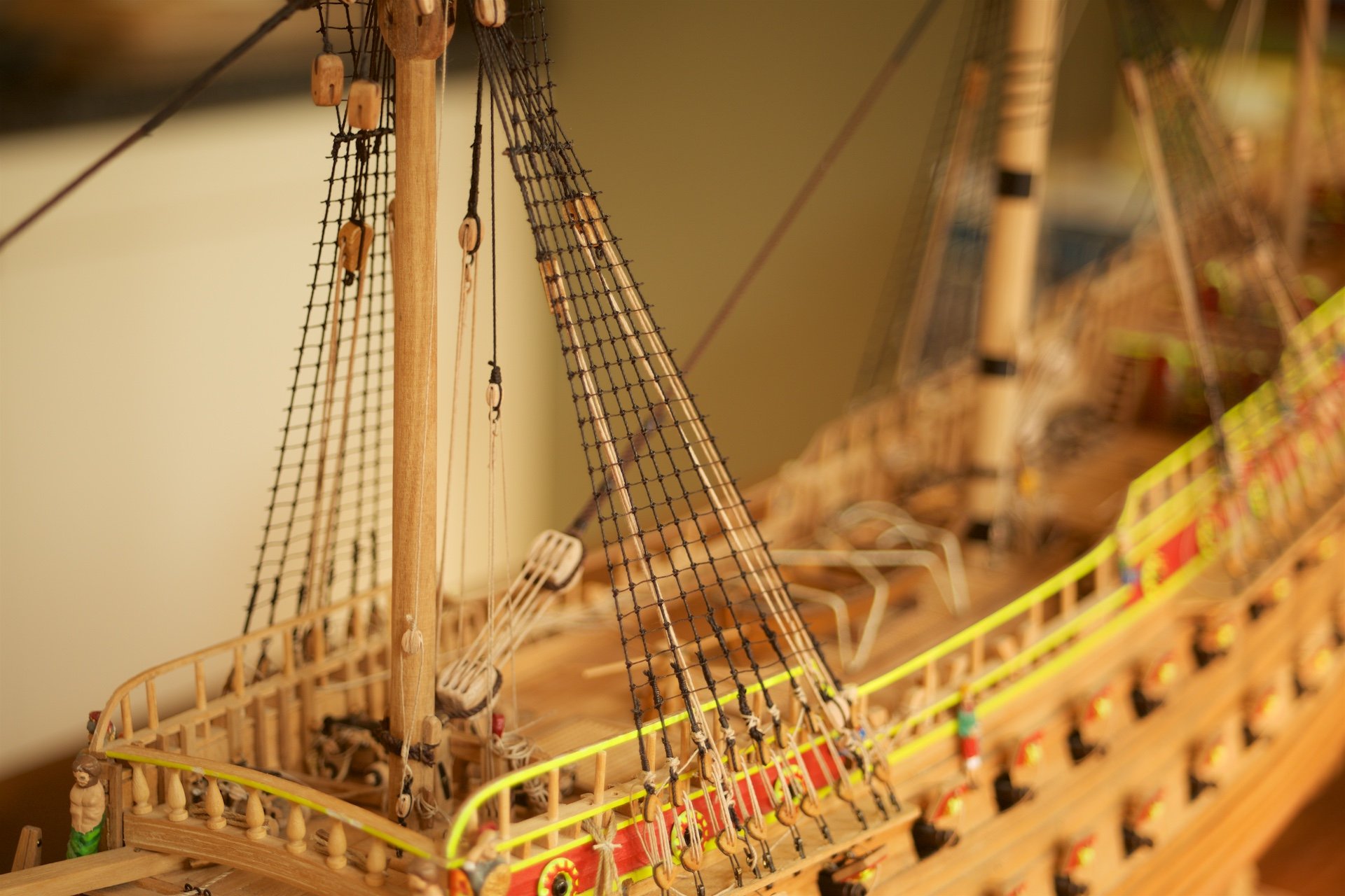
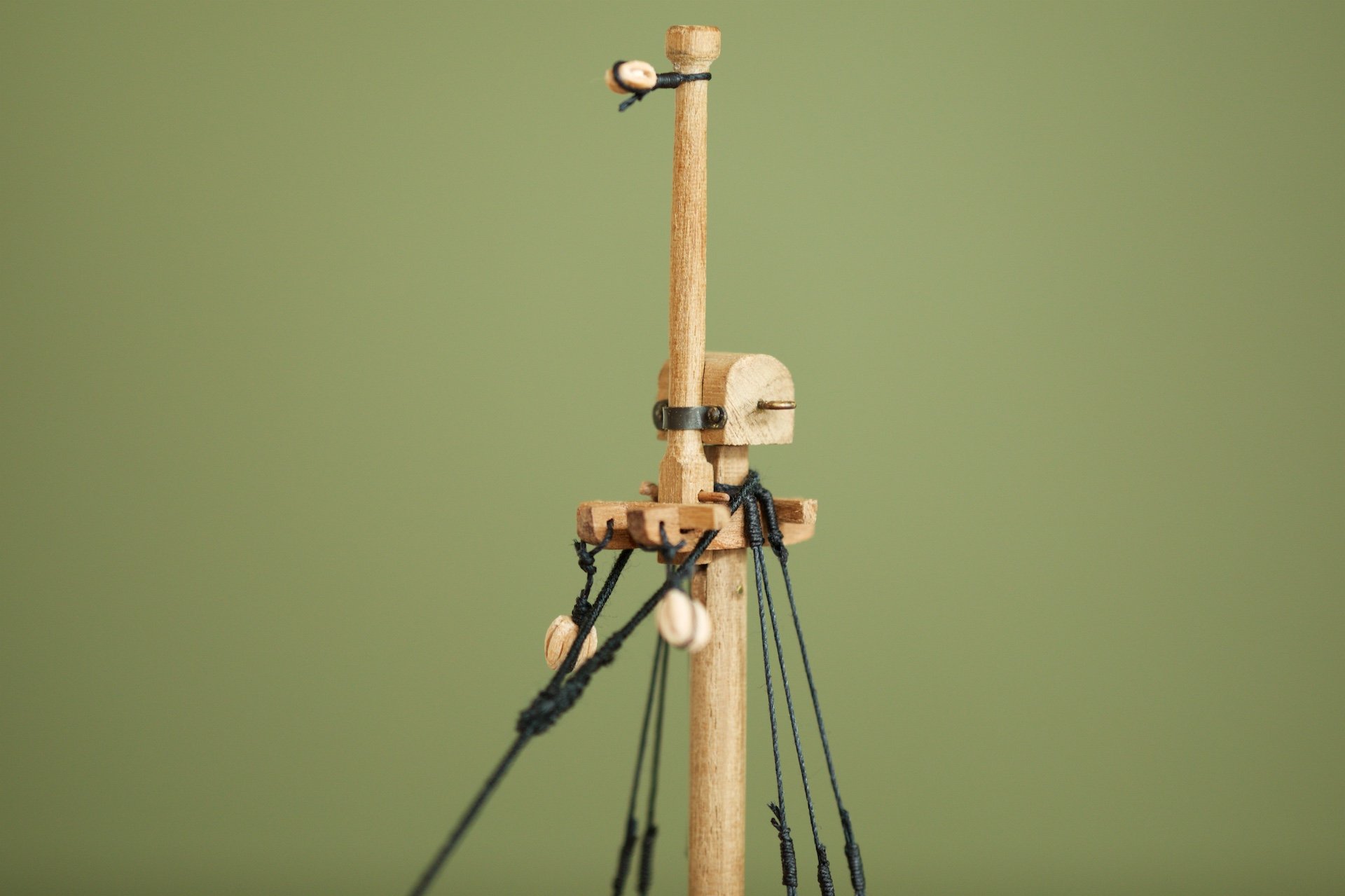
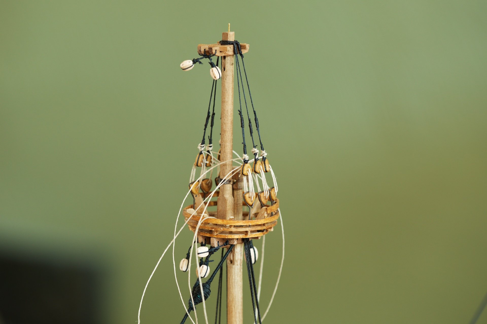
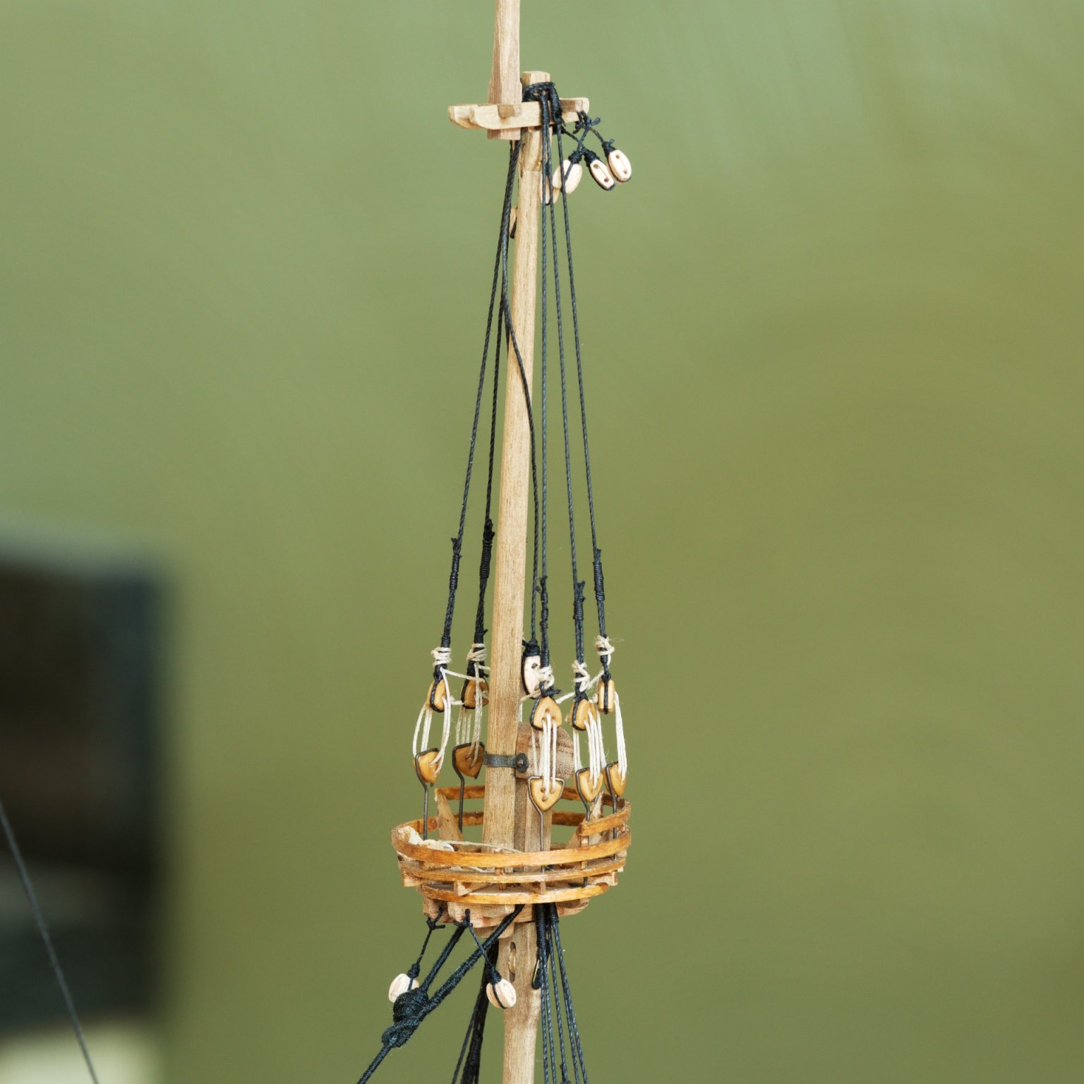
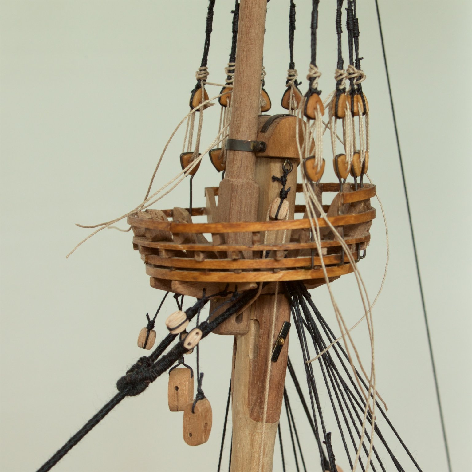
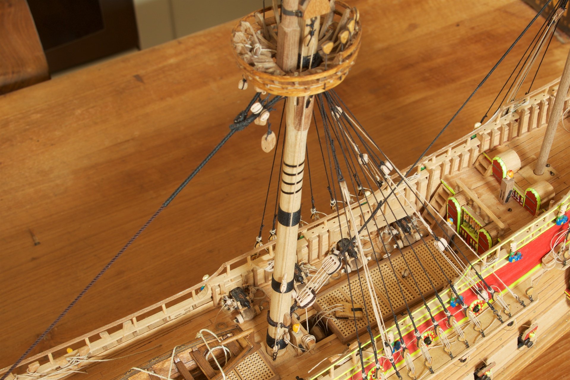
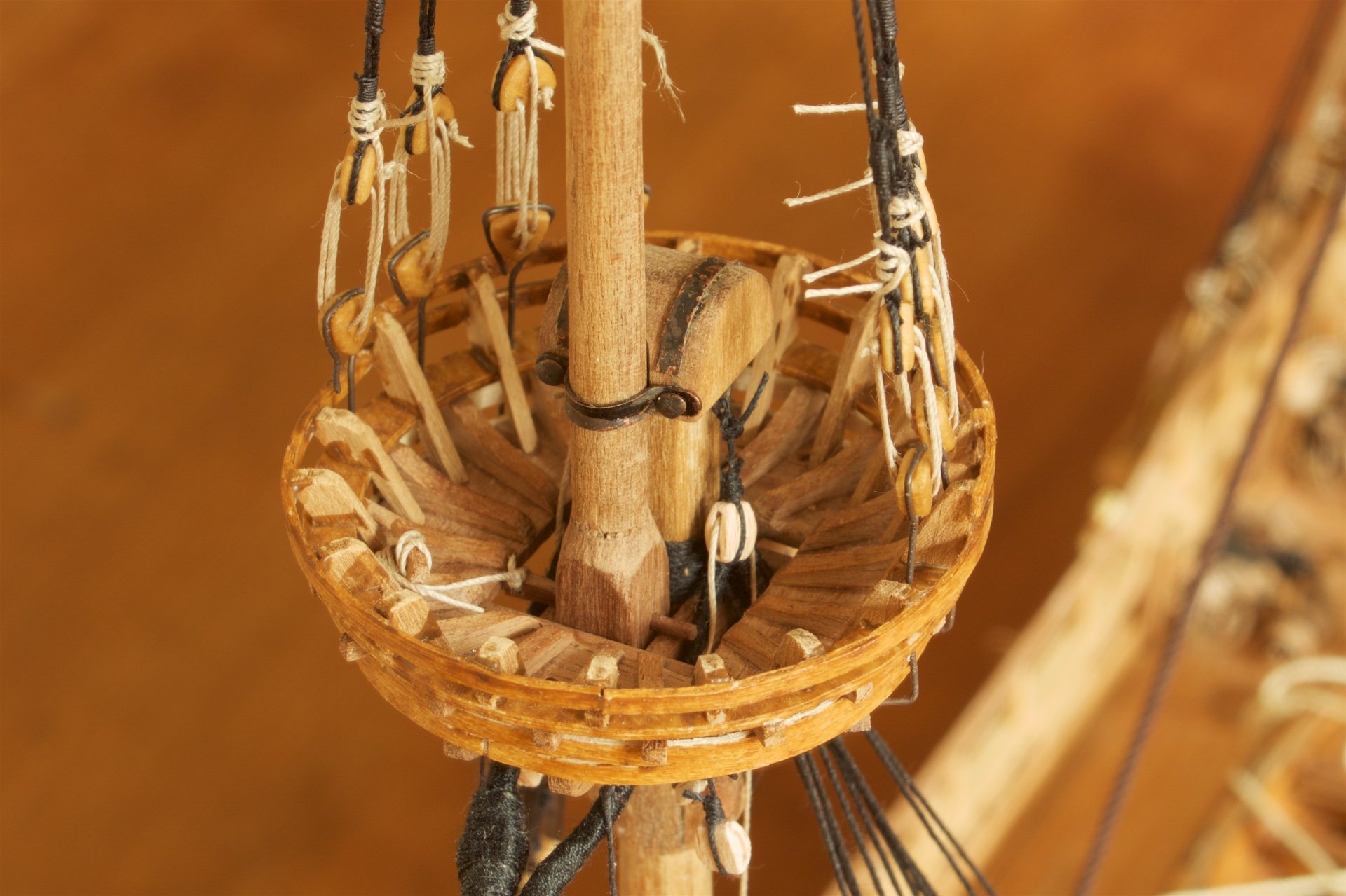
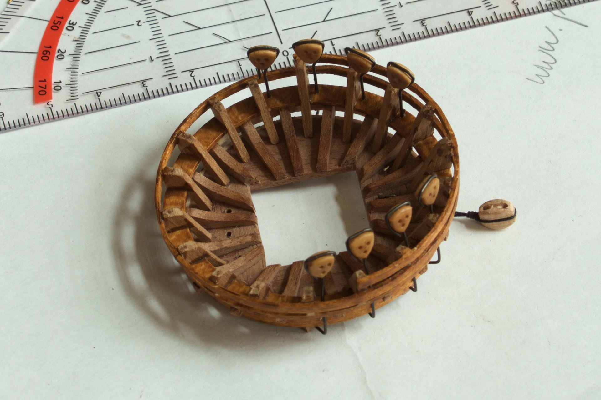
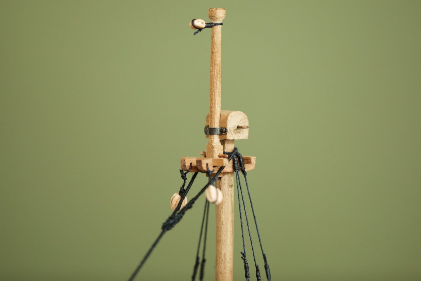
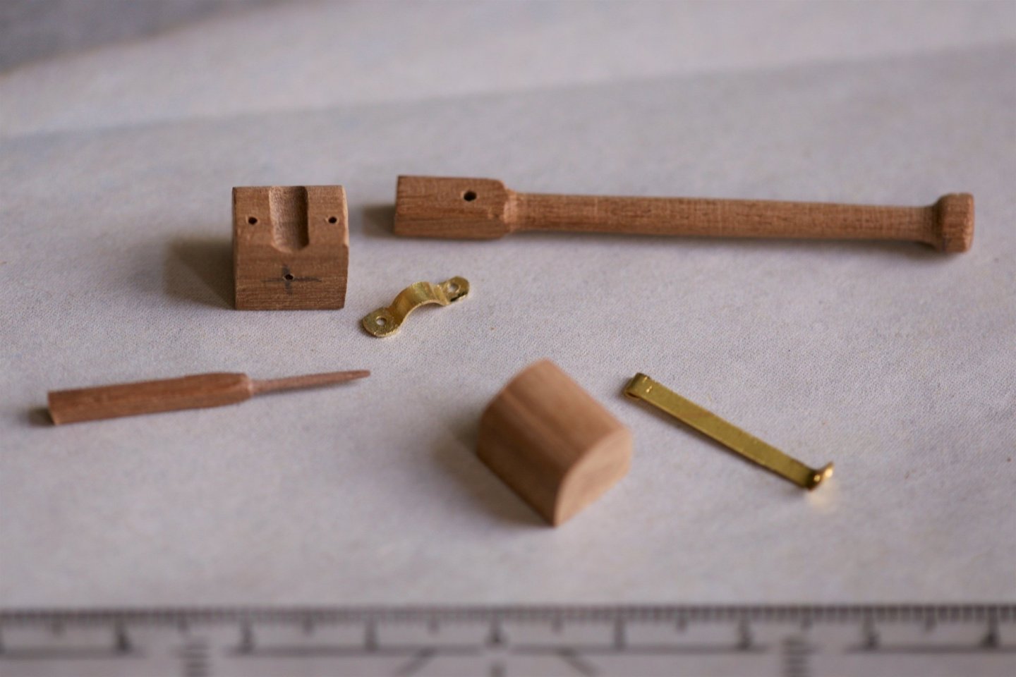
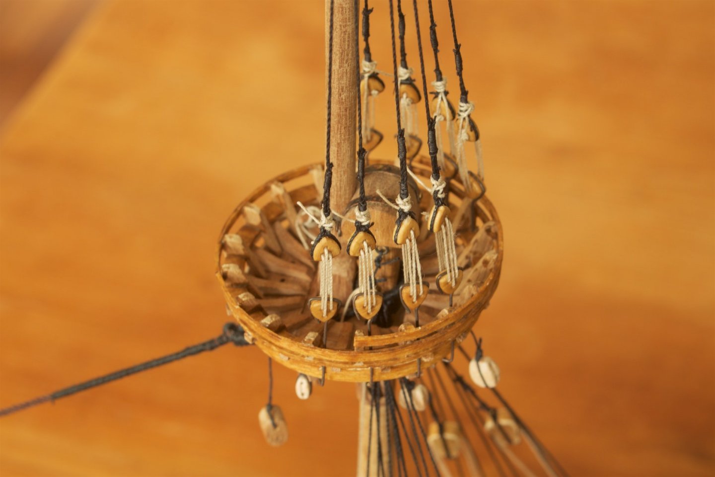
After making the lower part of the mizzen mast, I continued with the foremast. I made the cap from solid nut wood, of 15x15 mm. I had some metal parts that I could fit on them. I also made the cap already for the main mast, where the only difference is the diameter of the space for the mast part. I had not glued the second mast part on the lower part, but the construction is very stable after adding the shrouds. I had made the platform such that the space for the second mast part was just big enough to fit, including the somewhat extending axis for the sheave. The sheave of the second mast part was used for the line running from the cap, throught the sheave, again to the cap, and then to deck. The fid that keep the second mast part supported on the platform was connected with a small line to a small holder. I had seen these details in the build log of md1400cs, and it thought them to be a nice addition. The futtock shrouds, from the platform to the lower shrouds, will follow later.

-
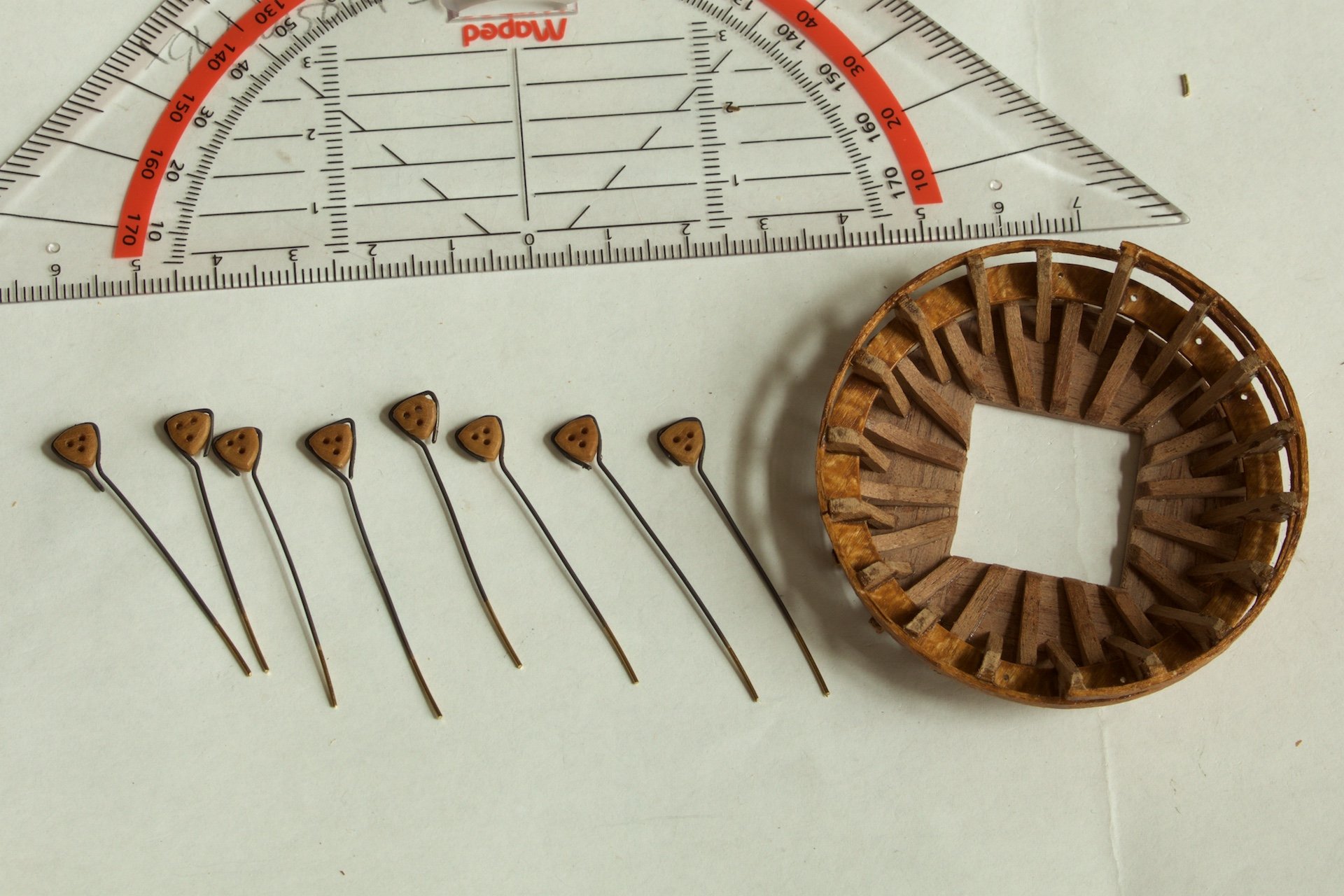
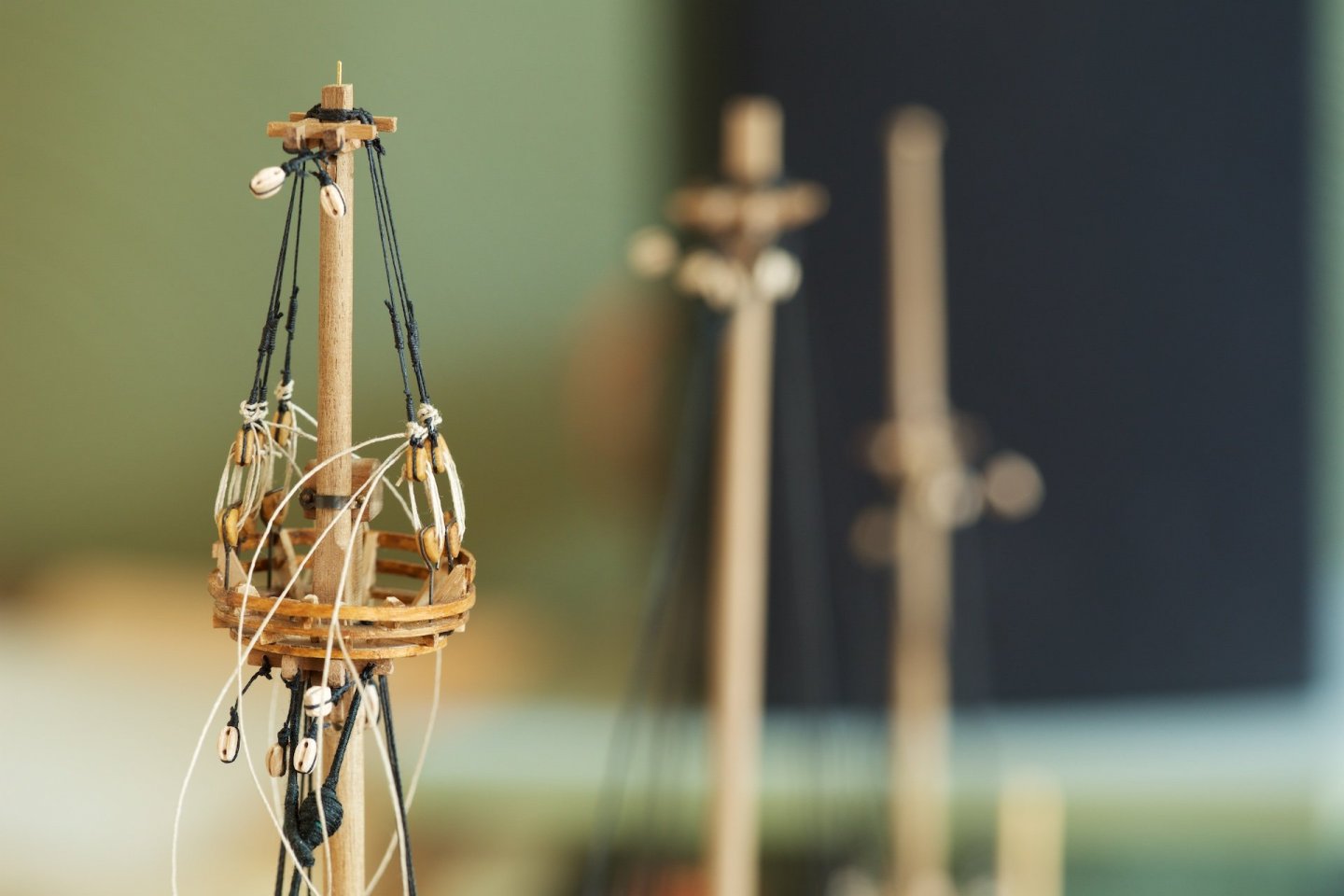
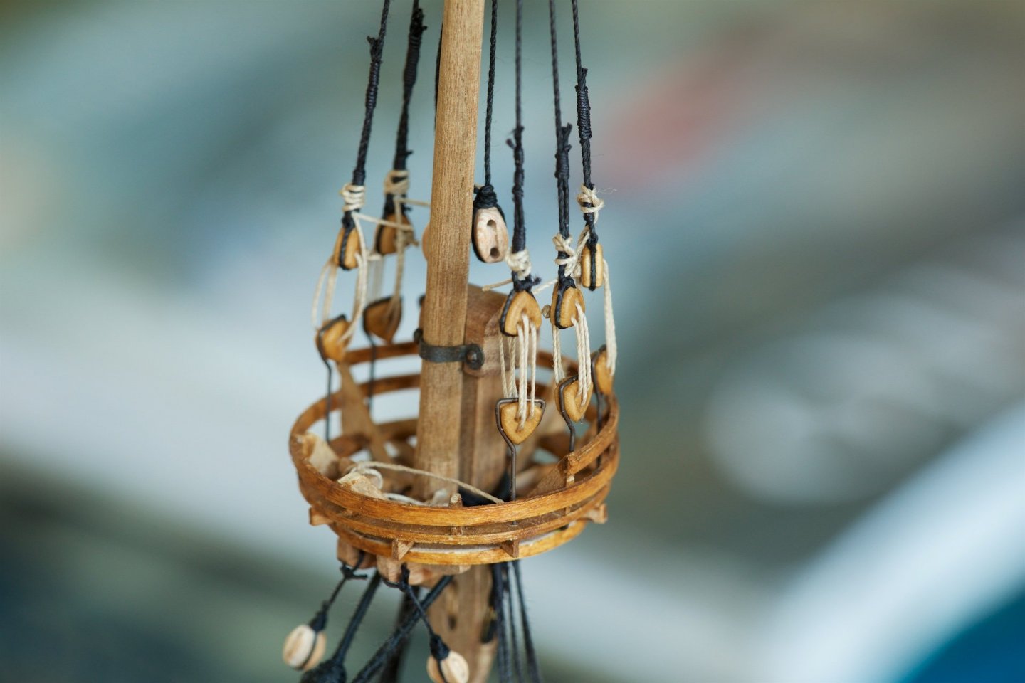
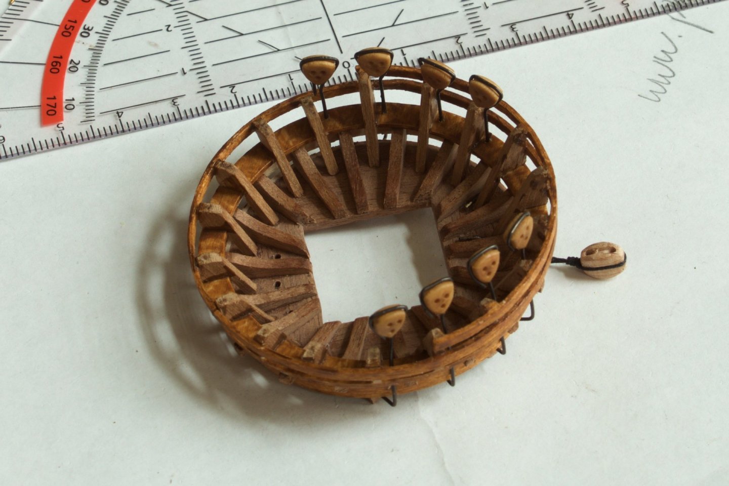
It has become almost routine, but still a lot of time spent on also making the tackles, the shrouds and the stay of the mizzen mast. And back to the foremast. Earlier, I had made the wooden parts of the platform. Now, the deadeyes attached. For the deadeyes on the wales, I had used clamps, but using such clamps here would not give enought height. So, I used copper wire. of 0.6 mm. The copper wire is bent alonf the bottom of the platform, and glued at the bottom, so that the angles and heights are as good as possible and these bents are then soon usable for attaching the hooks to prepare the shrouds between the platform and the lower shrouds.


-
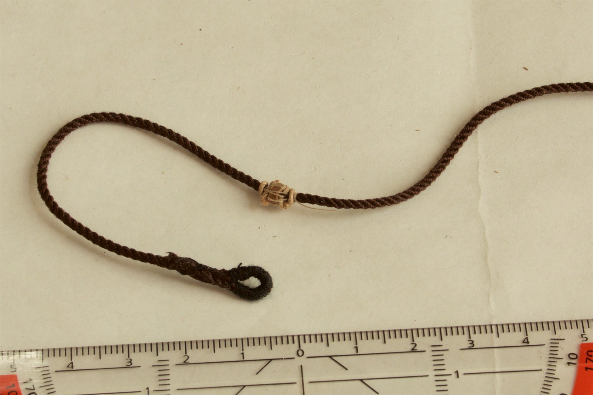
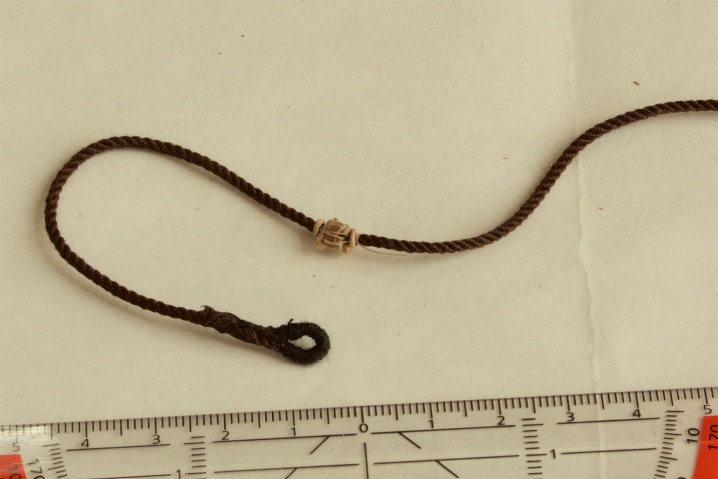
Now also the shrouds on the main mast attached. This time the spacing of the deadeyes is more even than was the case at the foremast. The mouse for the main stay, and the serving with black rope. Also this one proceeded easier than of the foremast. I now made the mouse itself smaller, without splicing and just with needle and some thread to fasten it. And some overviews of the ship as it is now.

-
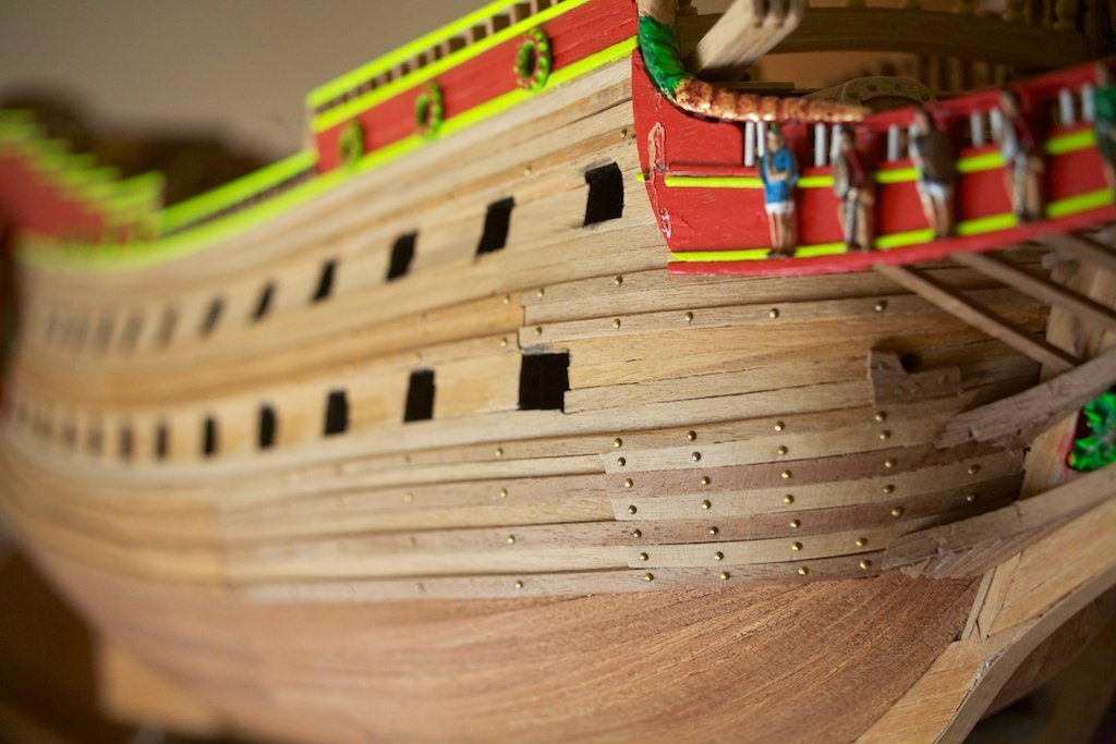
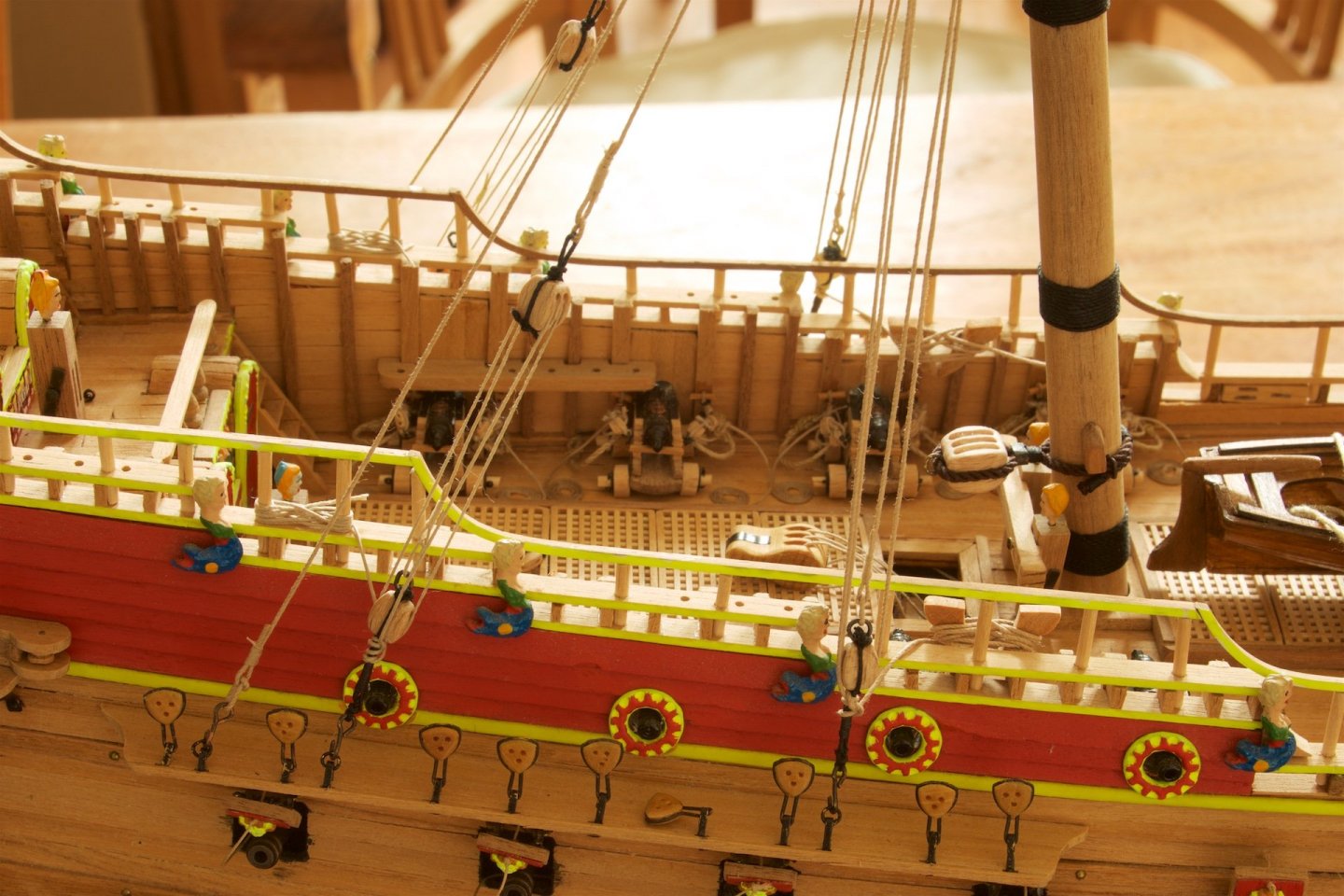
My photos from post #42 (in 2013), that are not visible anymore in the original post nr 42. This was about that I had finally decided to add nails into the hull. And the small side window, that I had added.
-
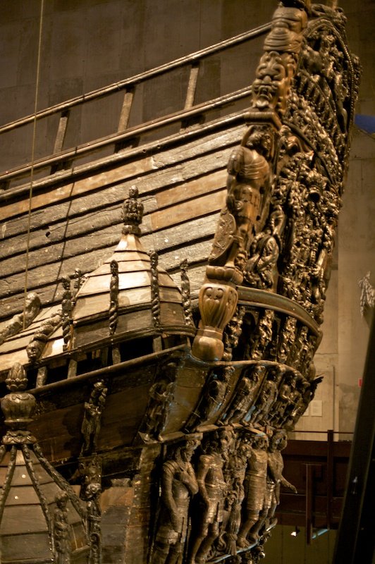
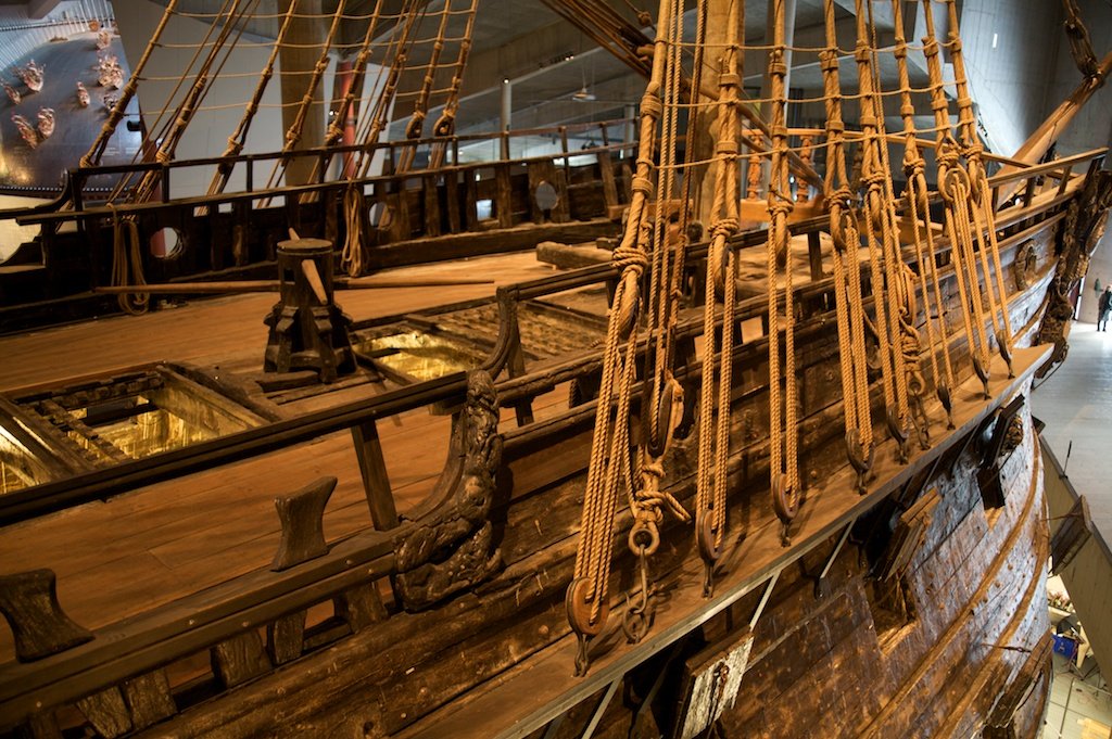
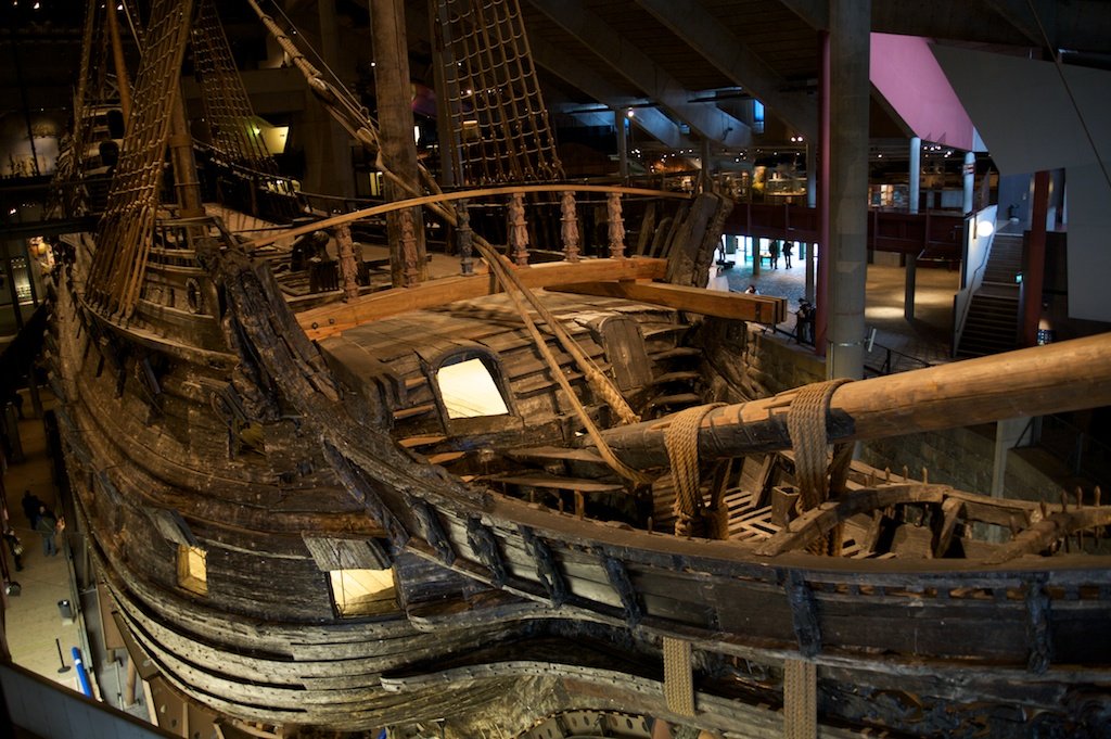
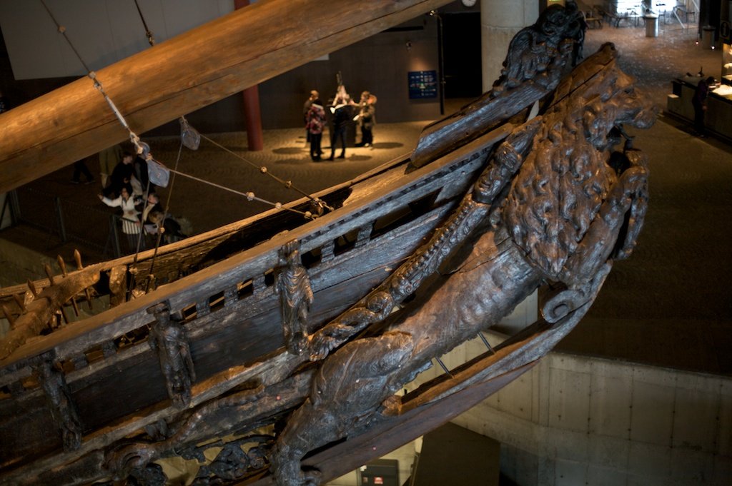
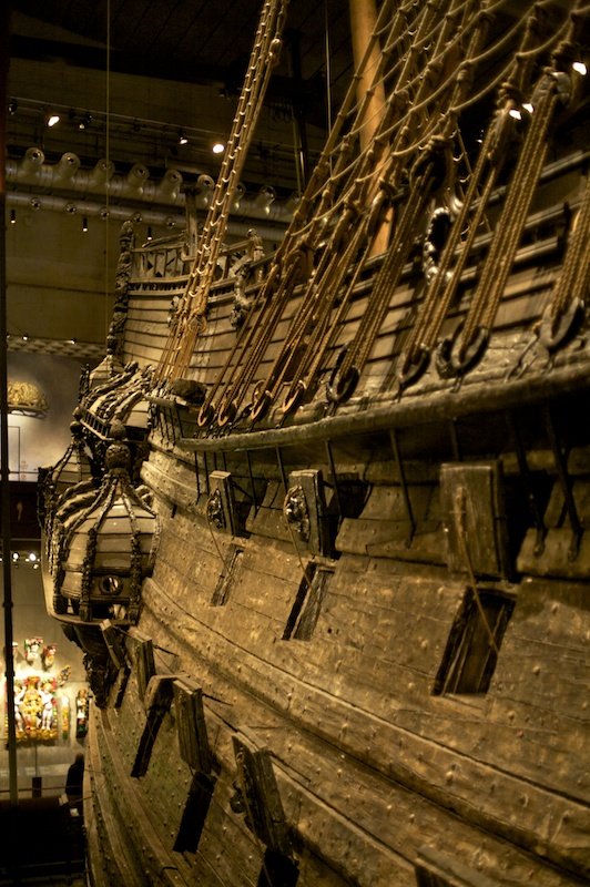
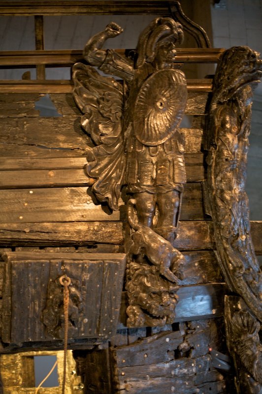
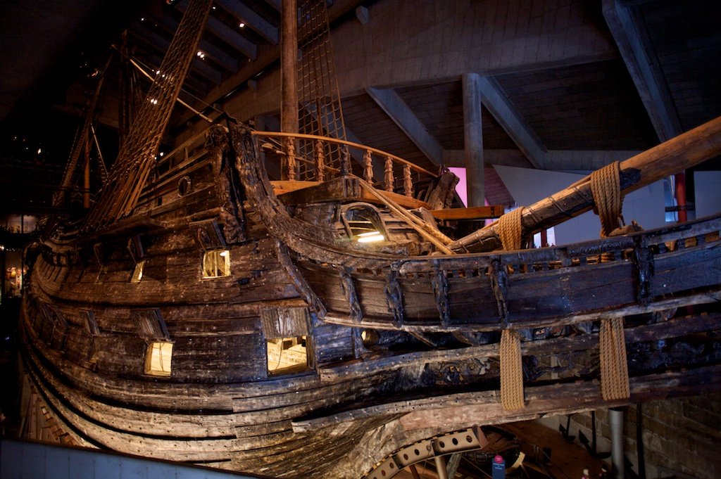
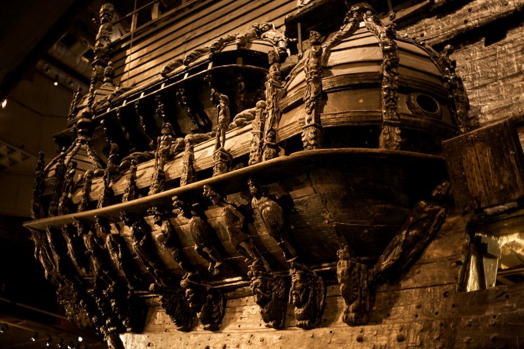
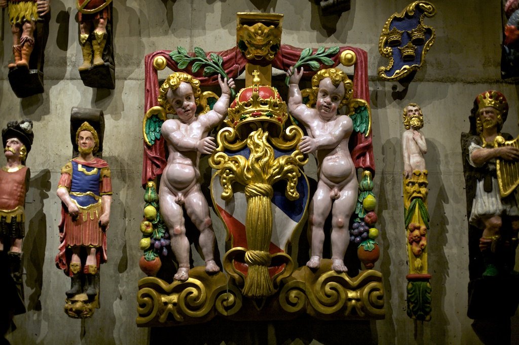
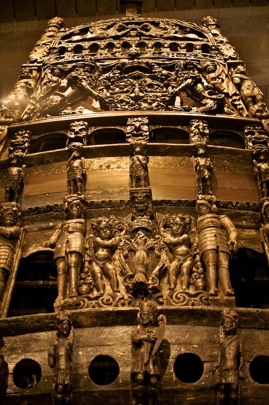
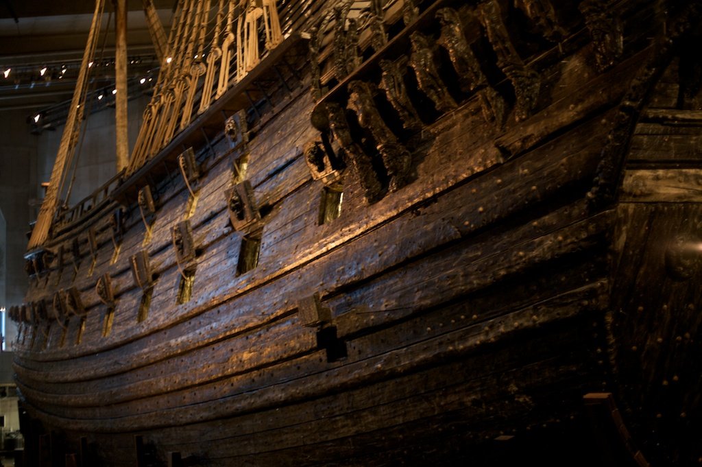
Hi Guy, Thank you for alerting me. I had not seen that those photos were not visible anymore. I do not know why these are not visible anymore. Now another try. First for the photos that I had taken myself in the Vasa Museum. At the time of my museum visit, I had not started with building a model of it, and also had not tought about it yet. So, with hindsight, I should have taken many other shots of different views as well.. So, corresponding to my earlier post #39:
-
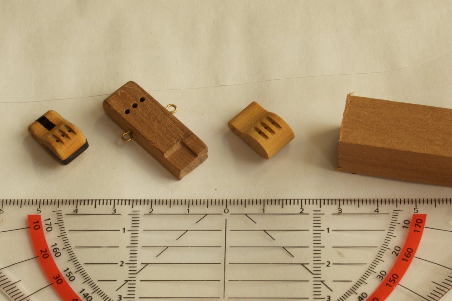
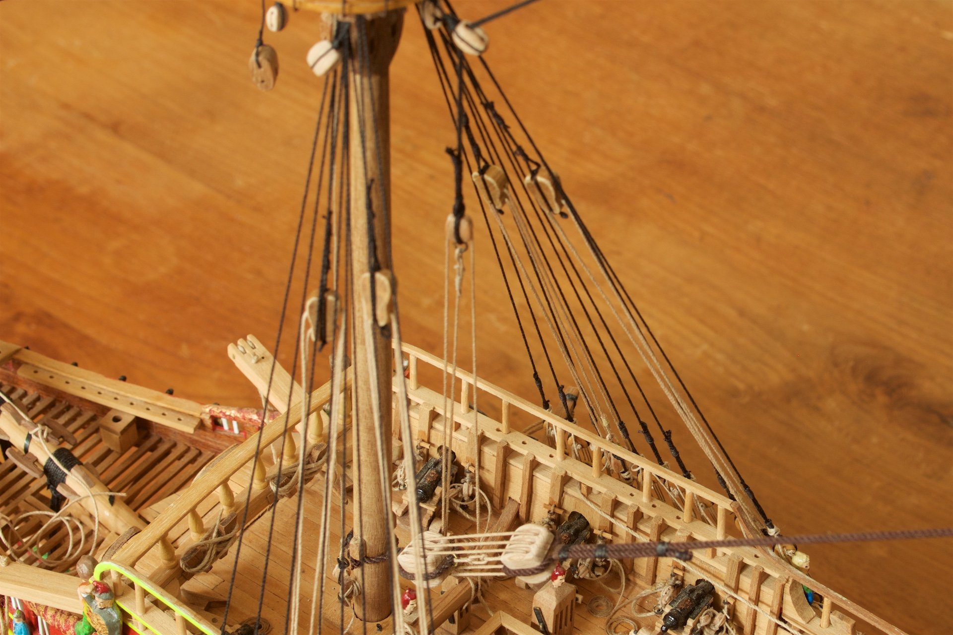
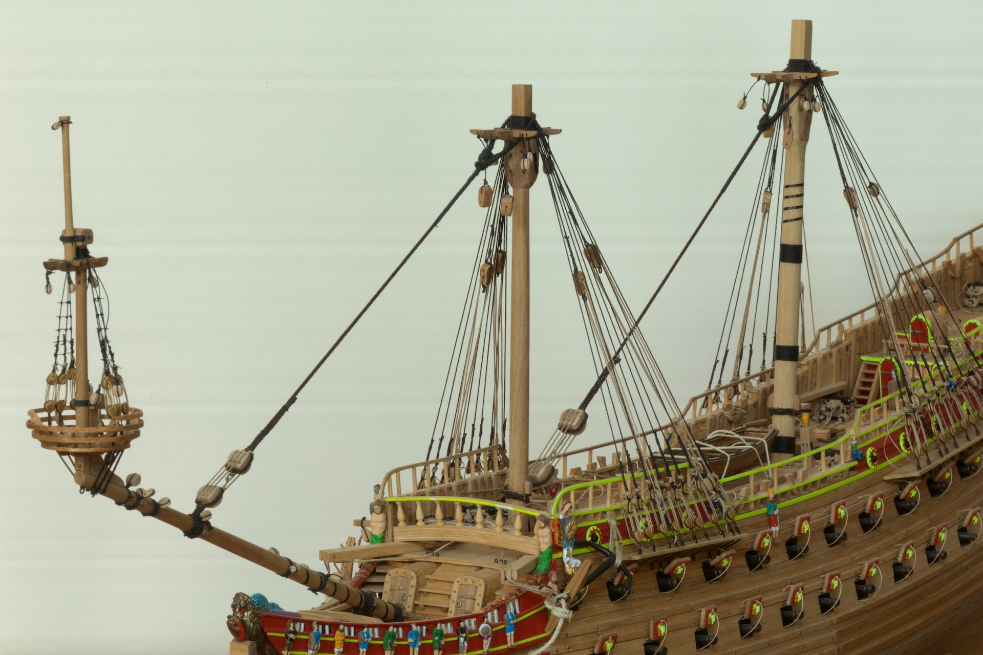
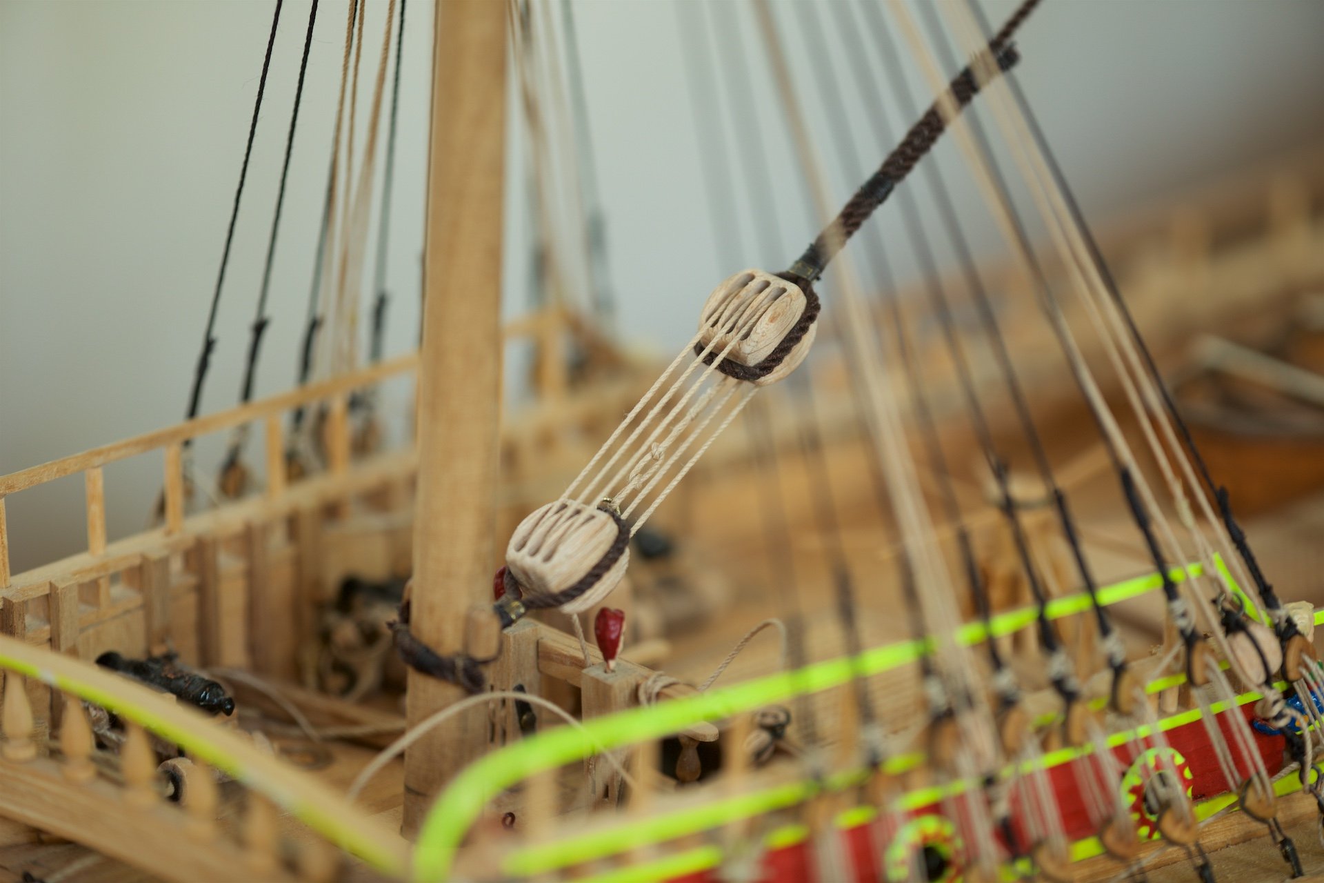
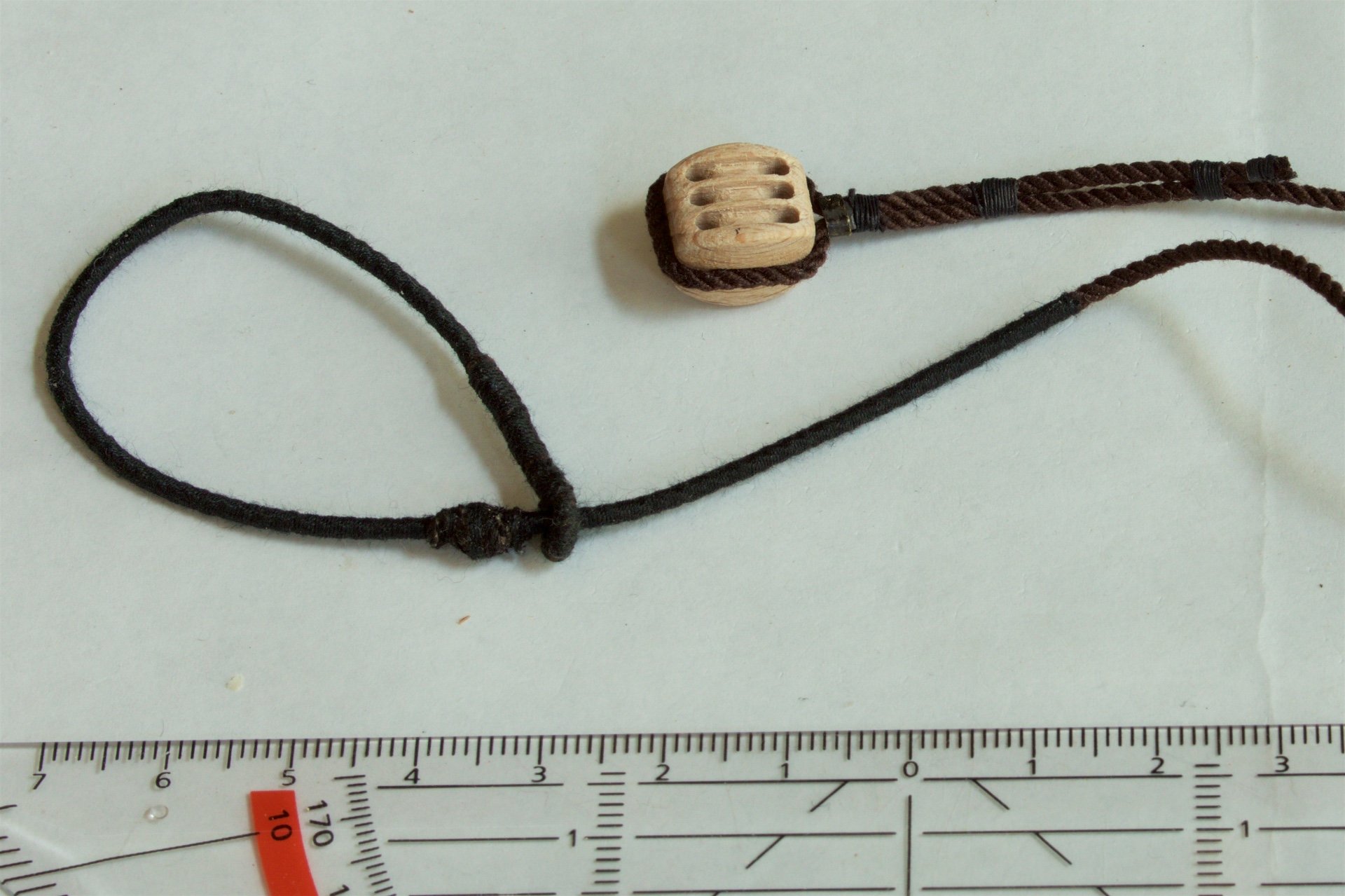
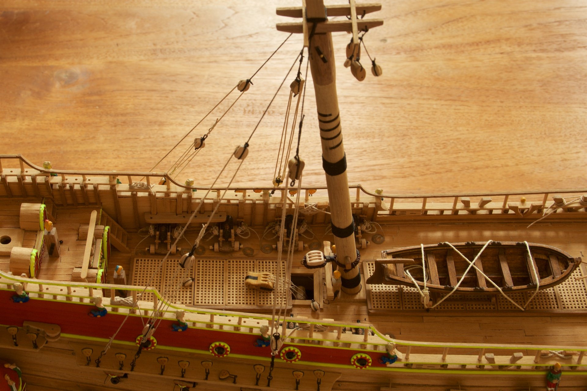
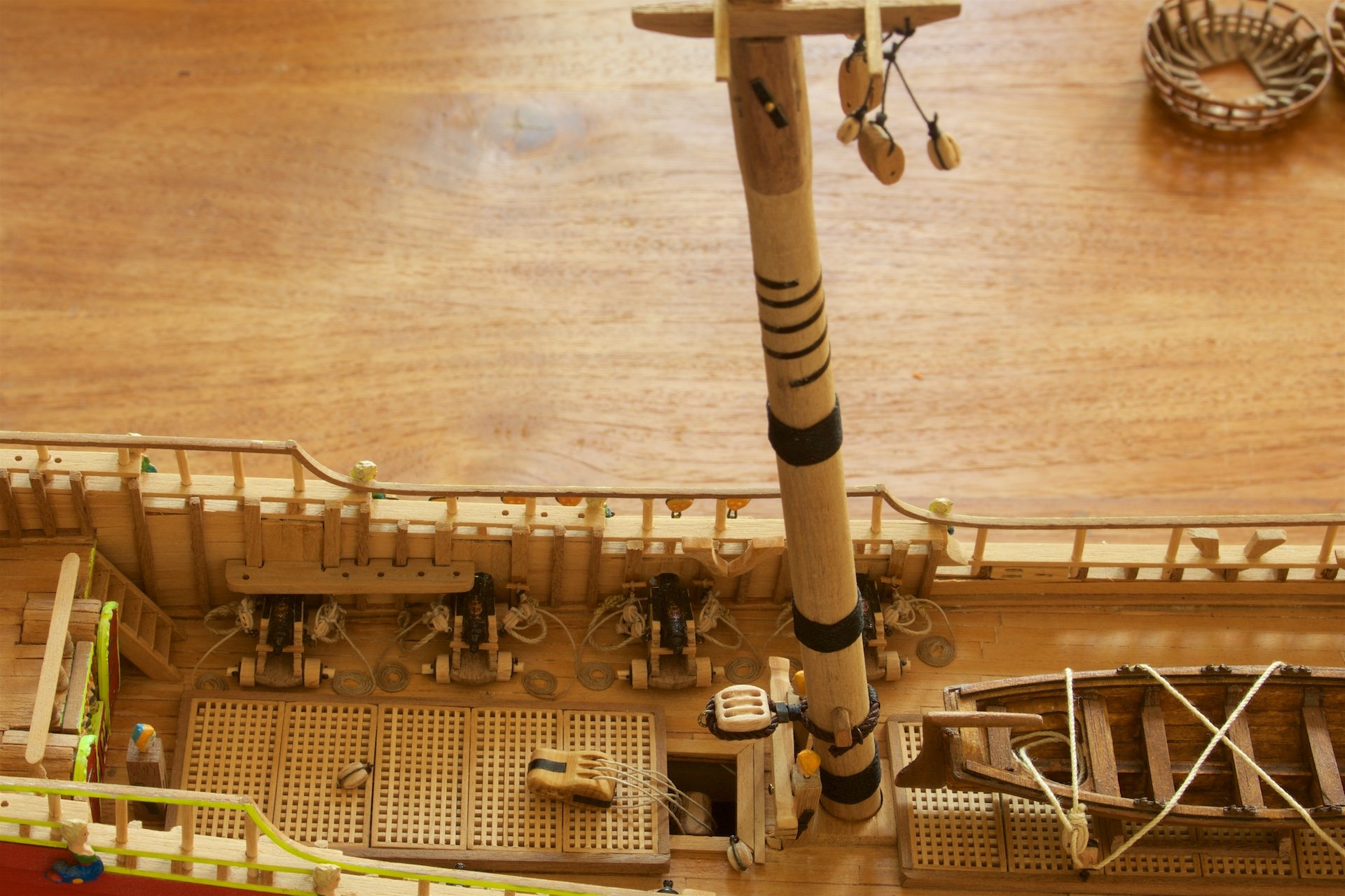
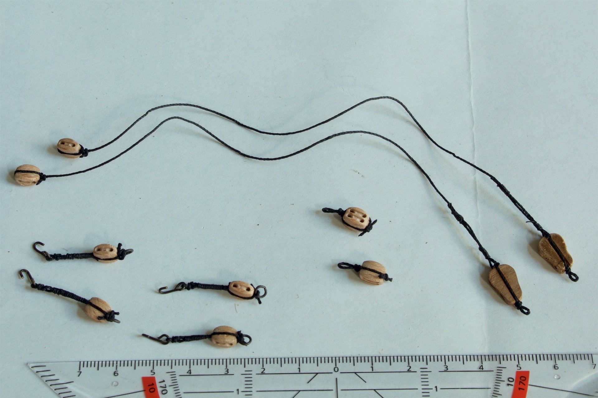
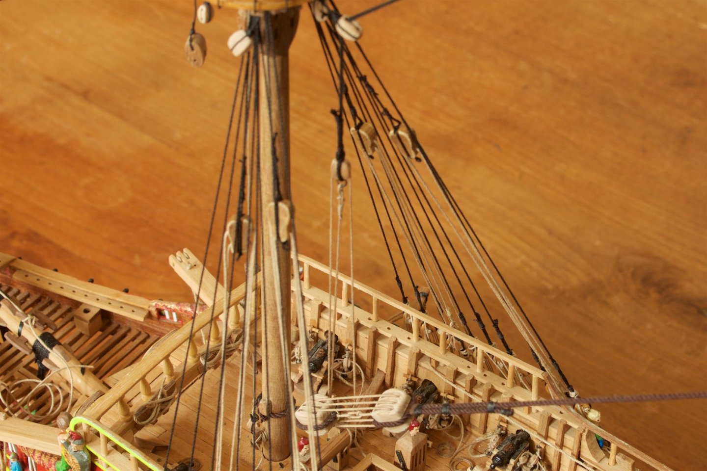
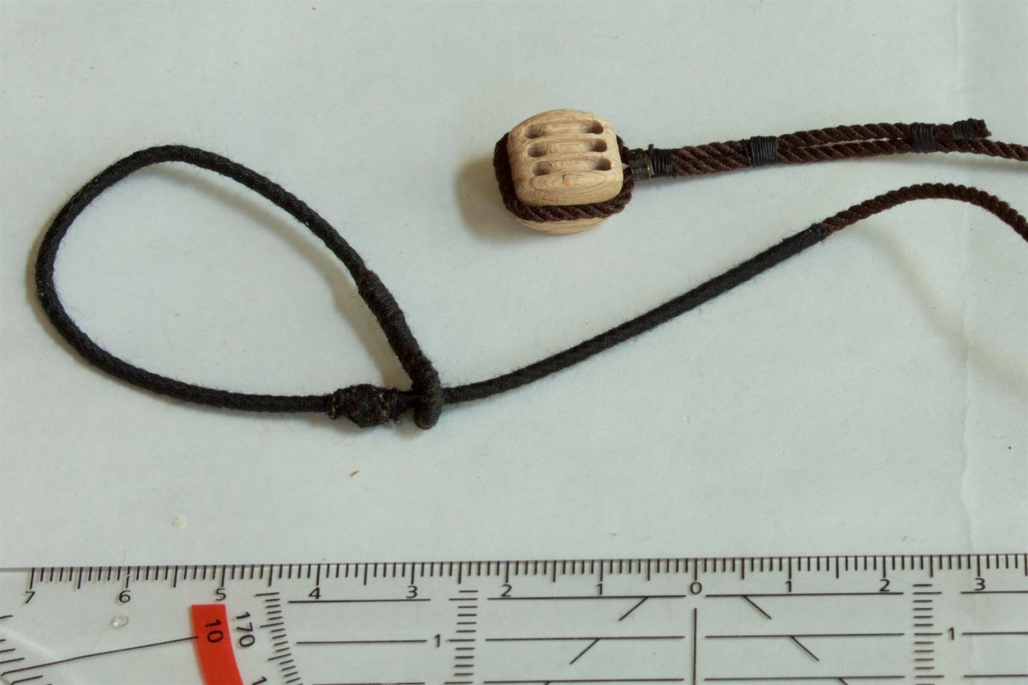
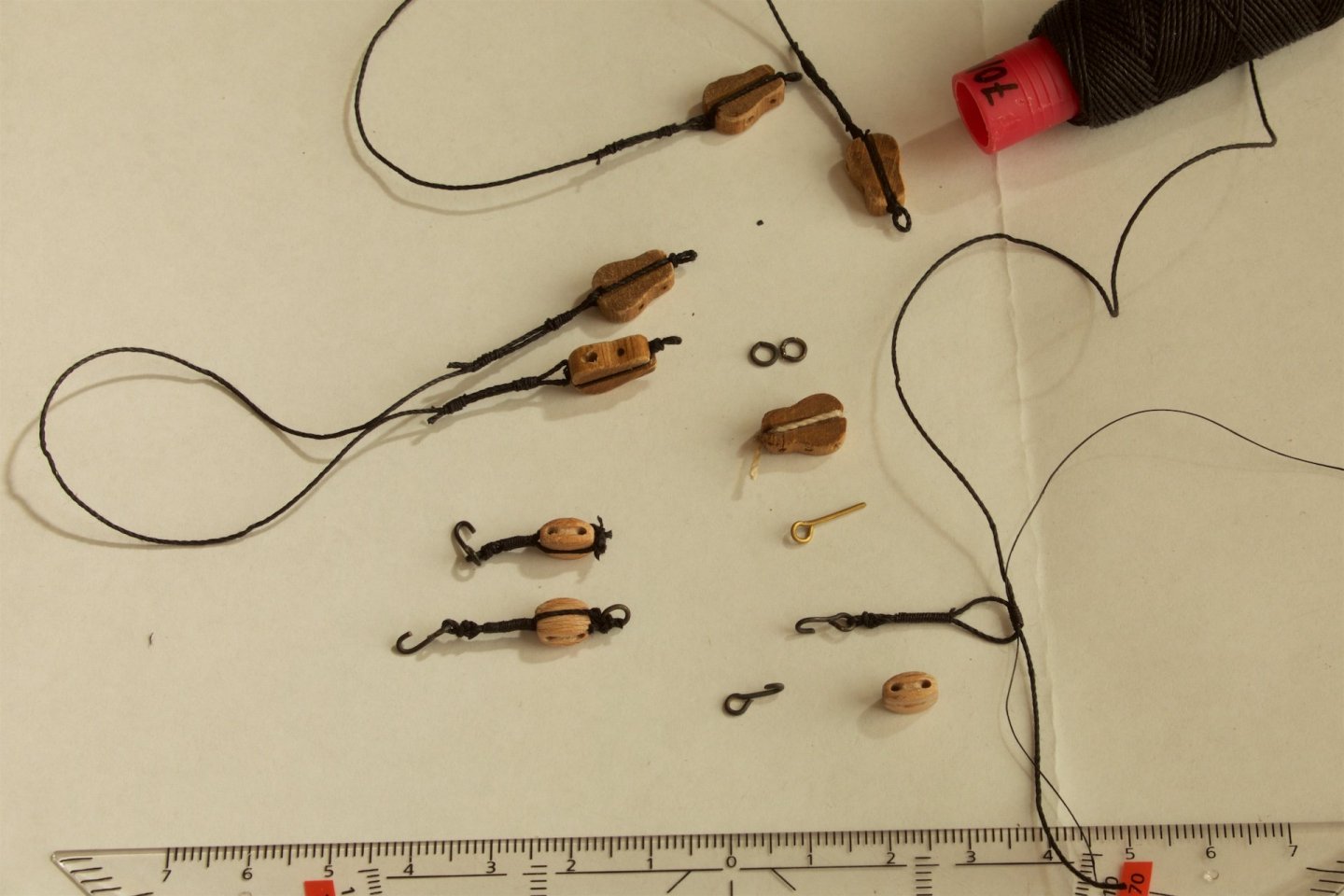
I have finalized the main mast itself, by making seizings around it. In most other builds, I see that brown/white rope is used for this. But I did so in black rope. This seems more logical to me, as this would probably be tarred rope. And in photos of the replica of the Batavia (in Lelystad, Netherlands), I also see black rope here. Further near the top, I added a thin band of black foil (which I had made at work..) to simulate a metal coil around the main mast. I had seen this in the build-log of md1400s, and it seemed to me a nice addition. Further, already attached the big block for the stay from the mizzen mast. And then made and installed the tackles on the main mast. The two tackles are here not the same as on the foremast, because now only one is with violin block and the other with a double block and with two attachments on the whales. The four violin blocks for the foremast and now one violin, I had somewhere in a box. But the sixth, I made myself, from nutwood and it looks actually better than the others..


-
I redid the serving of the rope, and also replaced the lanyards by thinner rope for the lanyards. It fits better to scale, and I noticed that it also runs better through the deadeyes, which made it actually easier to bring everything to tension. So, first part of standing rigging is done: shrouds and stay on the foremast.
-
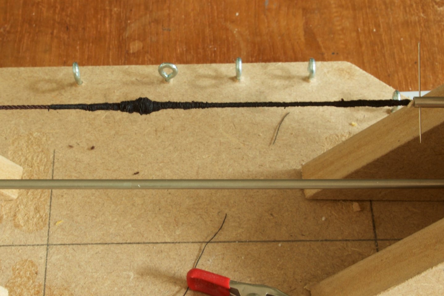
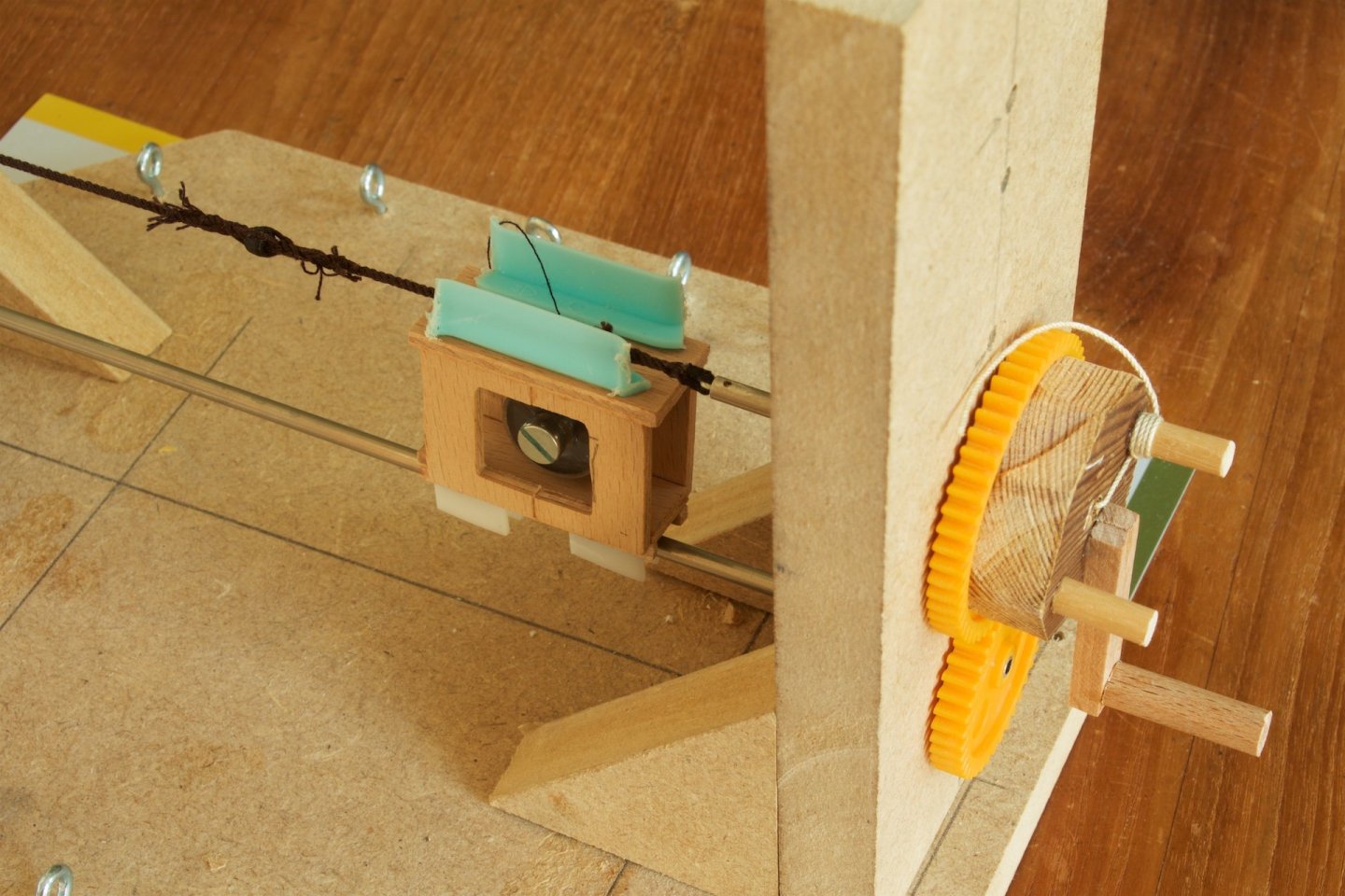
My next step is the making and attaching of the stay between the foremast and the bowsprit. This stay has a mouse and the rope is partly served. To be able to make this, I made my own rope serving machine. As guidance, I used the examples that I saw on MSW: https://modelshipworld.com/topic/5980-serving-machine-from-scratch/ https://modelshipworld.com/topic/4520-wrapper-ropes-serving-machine/ I have bought the gears, but all the other materials were left-overs. The tube is a 4 mm diameter metal tube. I have used it only one time yet. I noticed that it is essential to put a lot of tension on the rope, so a clamp is needed, as only tying the rope was not enough. The idea of the boxed encasing of the thread is that it automatically follows the winding. In my first run, I did not install it on the metal tube, but just left it at the bottom.. The rope for the stay is now served, including the mouse. Prior to the serving I made an eye splice and did some splicing for the mouse, for which I used a small wooden ring. The main difficulty was the serving around the mouse.

-
Great work! Both the modelship and the display case. I found your log when I searched for display cases within MSW. For my own model of the Wasa, I am not at that stage yet, but your display case will be a great inspiration. I read that you have sent someone a pdf of the design. Is this of the dimensions, as in your post nr 252 and 290?
-
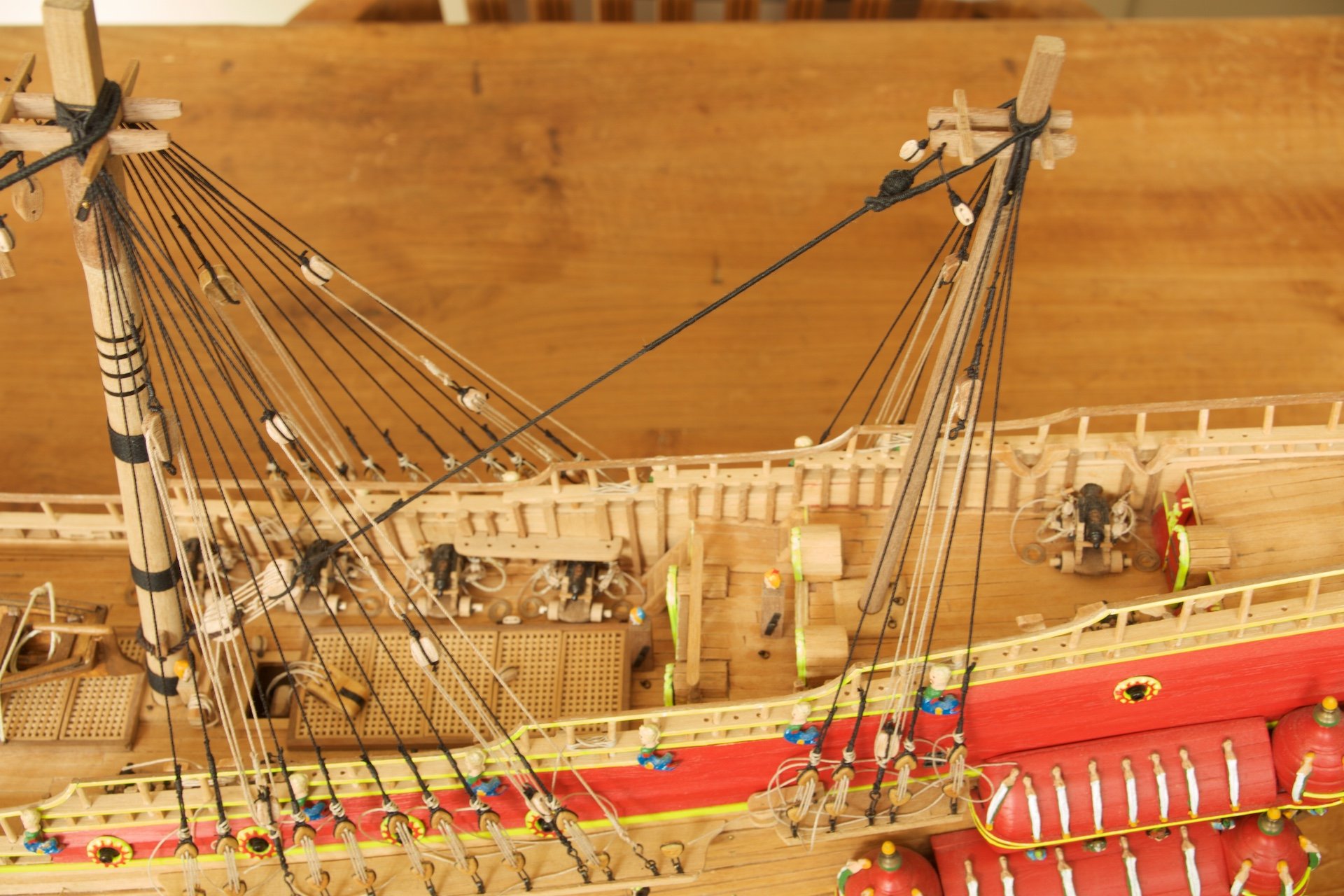
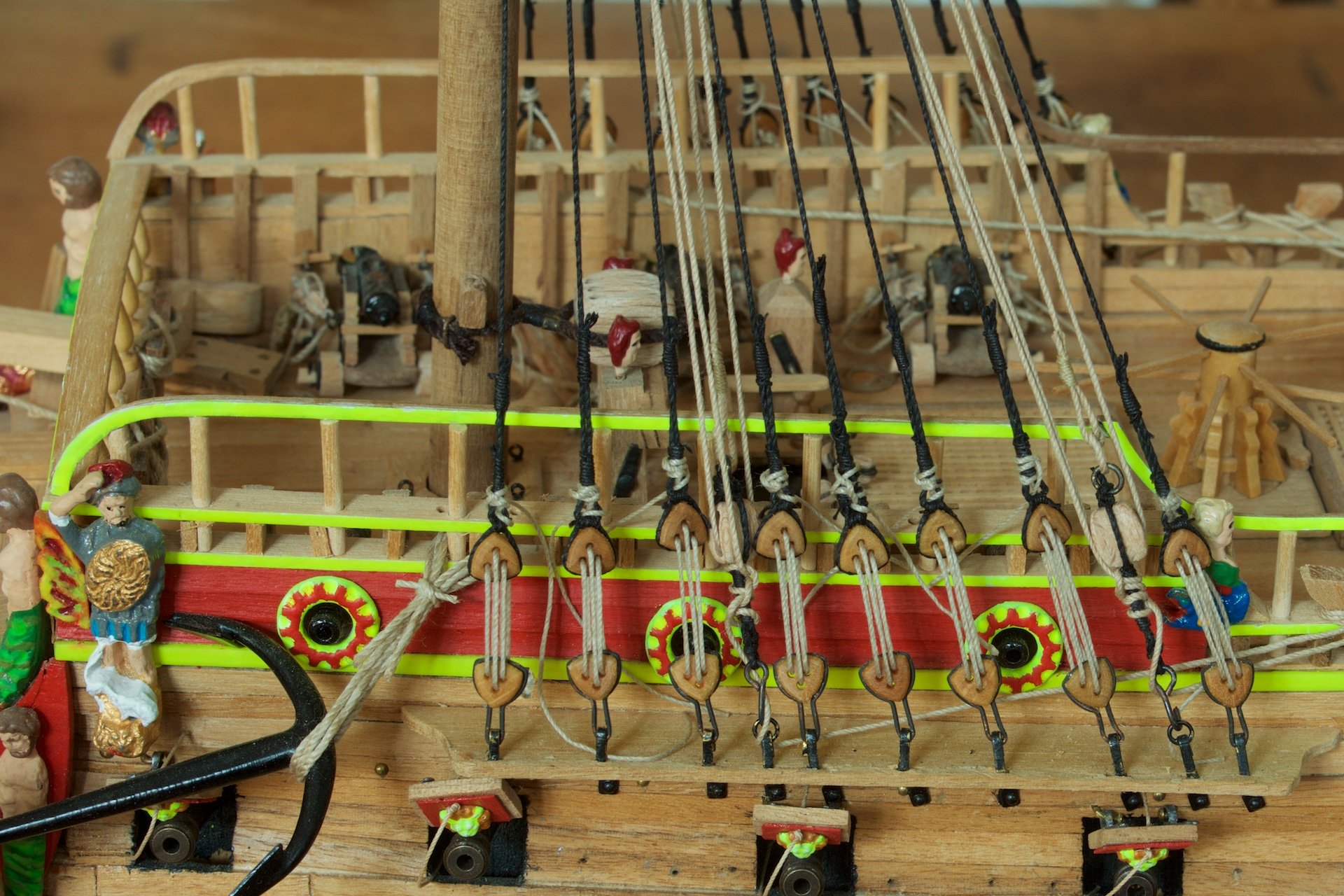
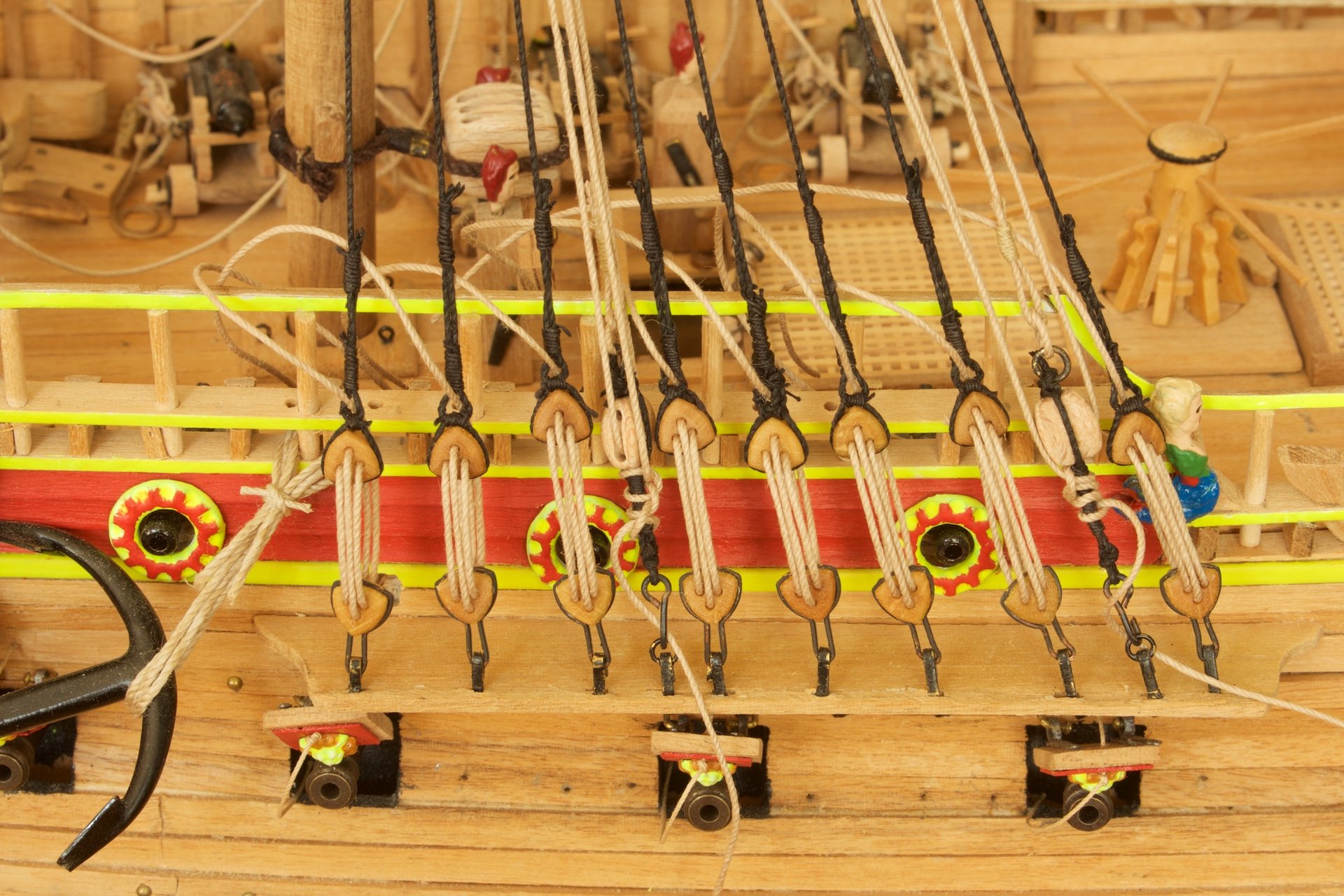
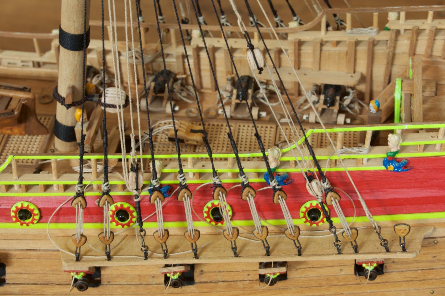
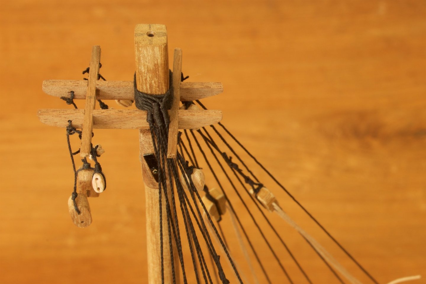
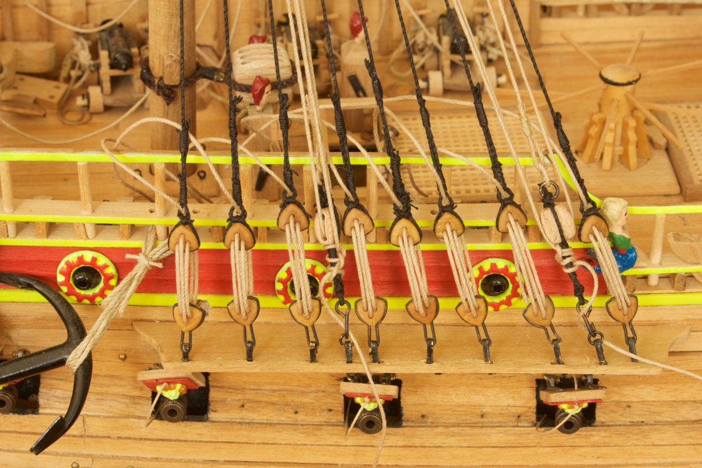
Continueing on the foremast: I have made the shrouds. I used 0.8 mm thick (as mentioned in Corel instructions) black rope for the shrouds themselves. The lanyards are almost as thick (I used rope that did not have a thickness marking on it). Perhaps this is too thick, as the Corel instructions indicate 0.25 mm. Perhaps that I will change them, or otherwise I will use the smaller rope at the upper level shrouds, like I did with the bowsprit. One advantage of the thicker lanyards is that there is automatically a lot of friction, so even without tying the ends, the shrouds remain under tension. I noticed, that after a day already some lanyards needed some extra tensioning, because of loosening of the rope. I will wait with tying until also the foreward stay is attached. The horizontal alignment of the triangular deadeyes is not perfect, but I am satisfied enough with it. Also the top of the mast looks very tidy, with the 10 ropes nicely above eachother.
-
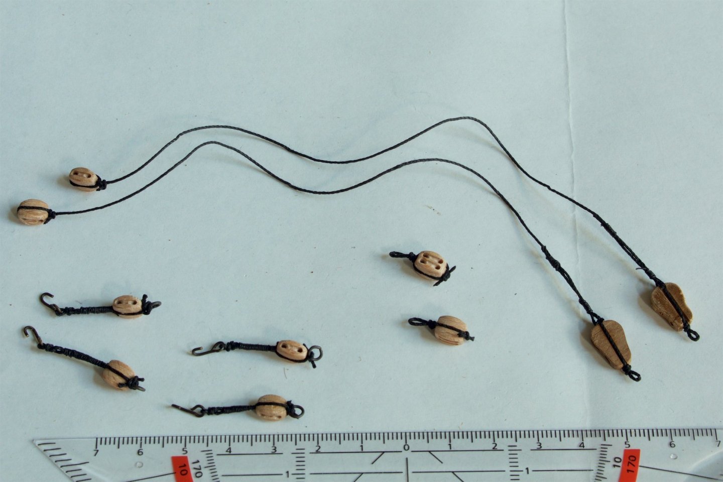
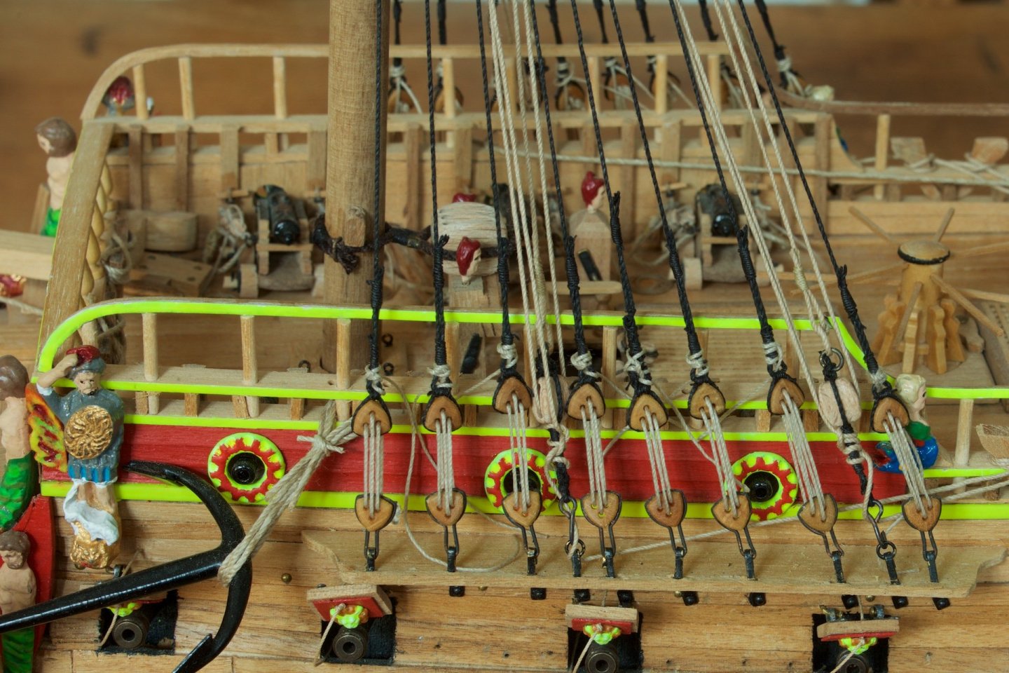
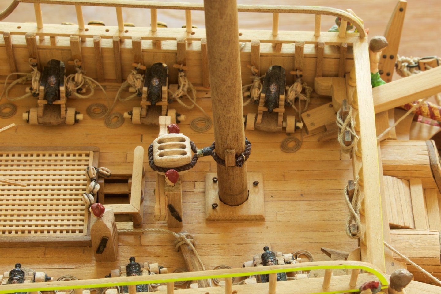
I had previously already made the masts, and now I attached the big block for the main stay. This is a 12 mm block. I used big rope to attach it to the mast, using both a clamp and a winding to secure it. At the back of the mast, I used again a winding and then two clamps to make sure that it stayed at the mast. I had seen this in the build-log of md1400cs, where I also found a reference to the Vasa museum discussion in which it was explained that for the Vasa, the foremast was made of one pole. So, no windings around the foremast. Next step at the foremast: making and attaching the tackles. The Corel instructions mention that backstays are attached to the eyes on the channel, but the museum and the 1/10 model in the museum have tackles here. So, I chose tackles, and attached the end of the rope on the block, as I had seen on a Vasa museum photo. A tedious job to make the tackles. I used violin blocks, and 7 mm blocks. I used windings to create some distance between the block and the hook.
-
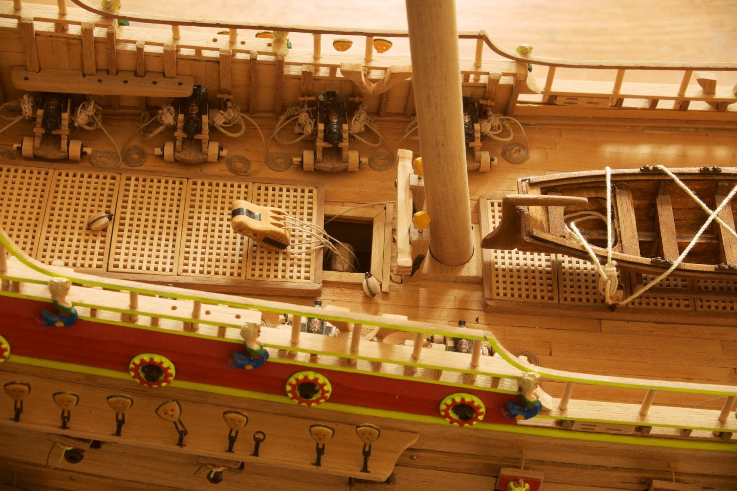
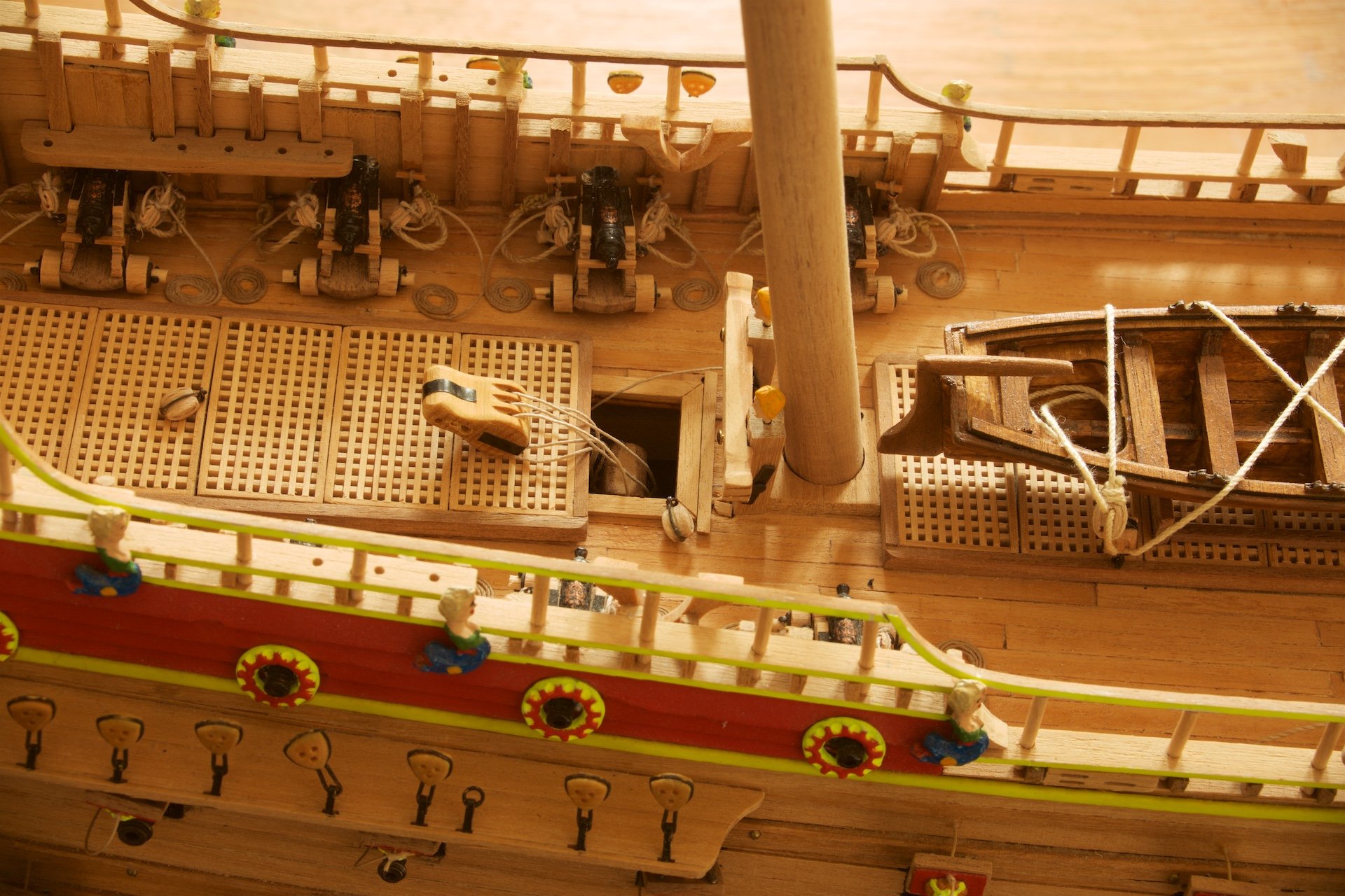
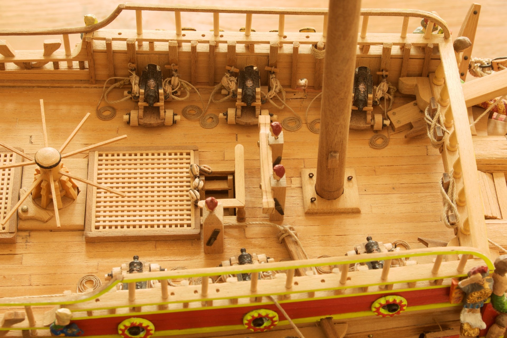
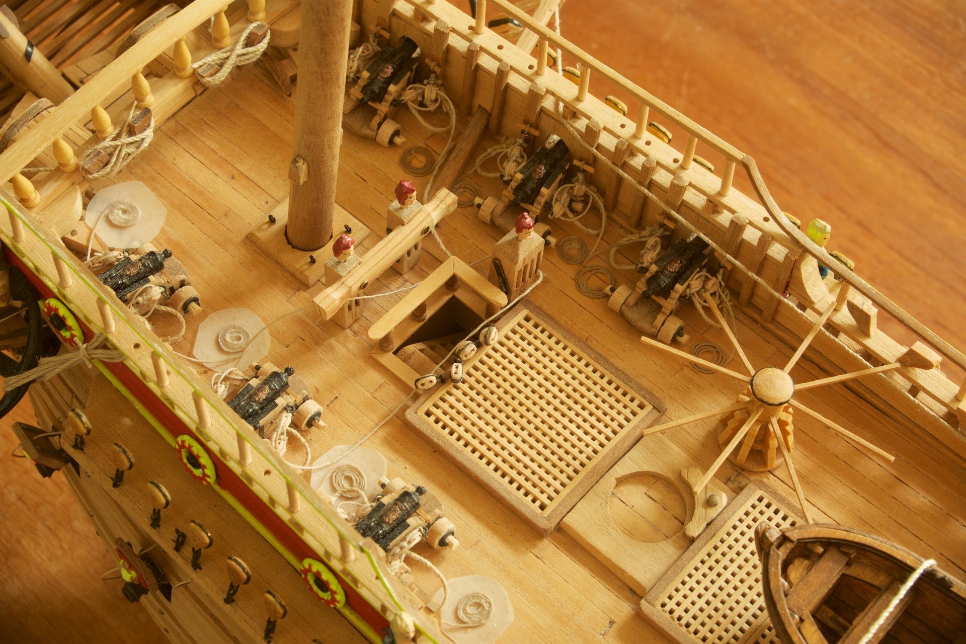
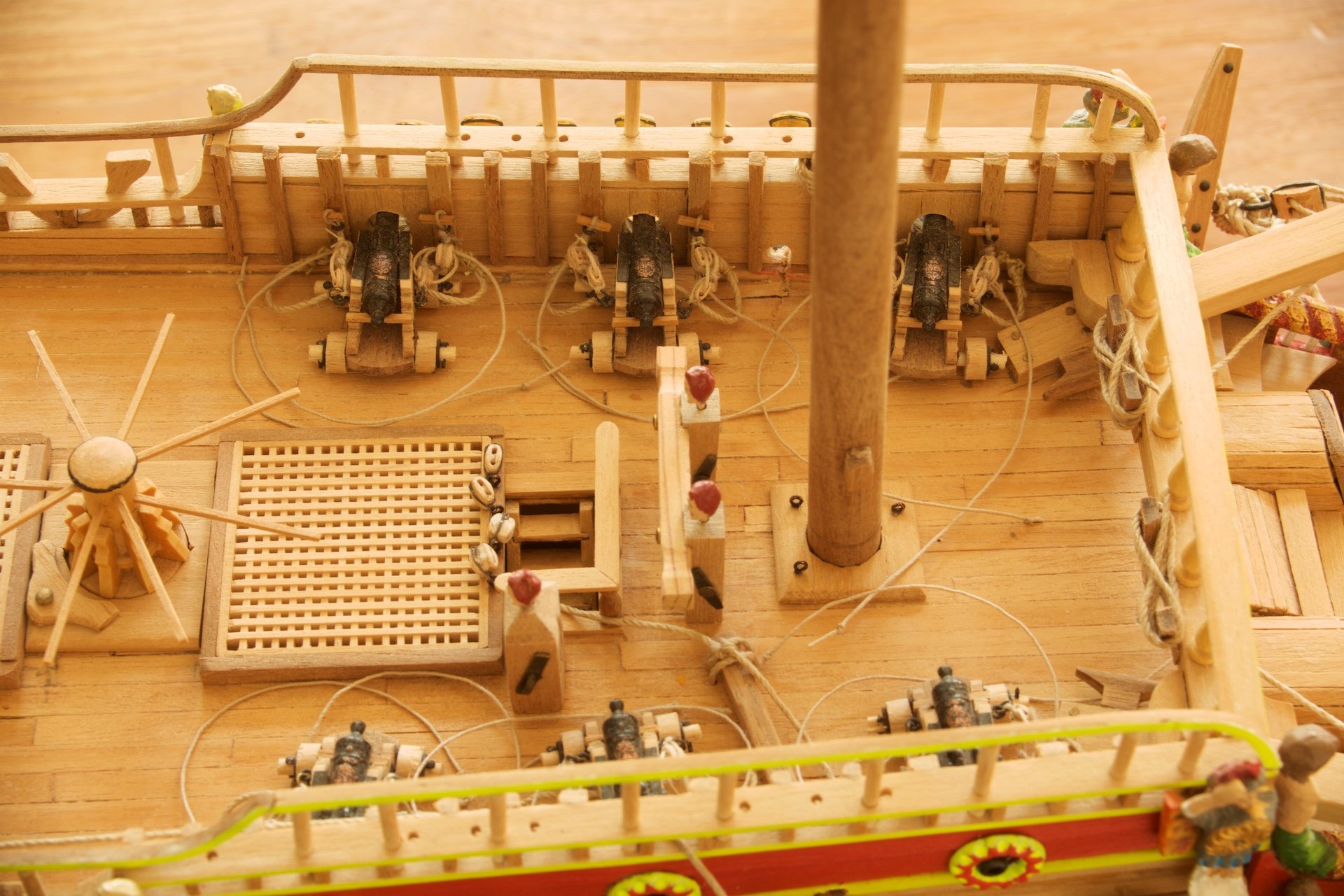
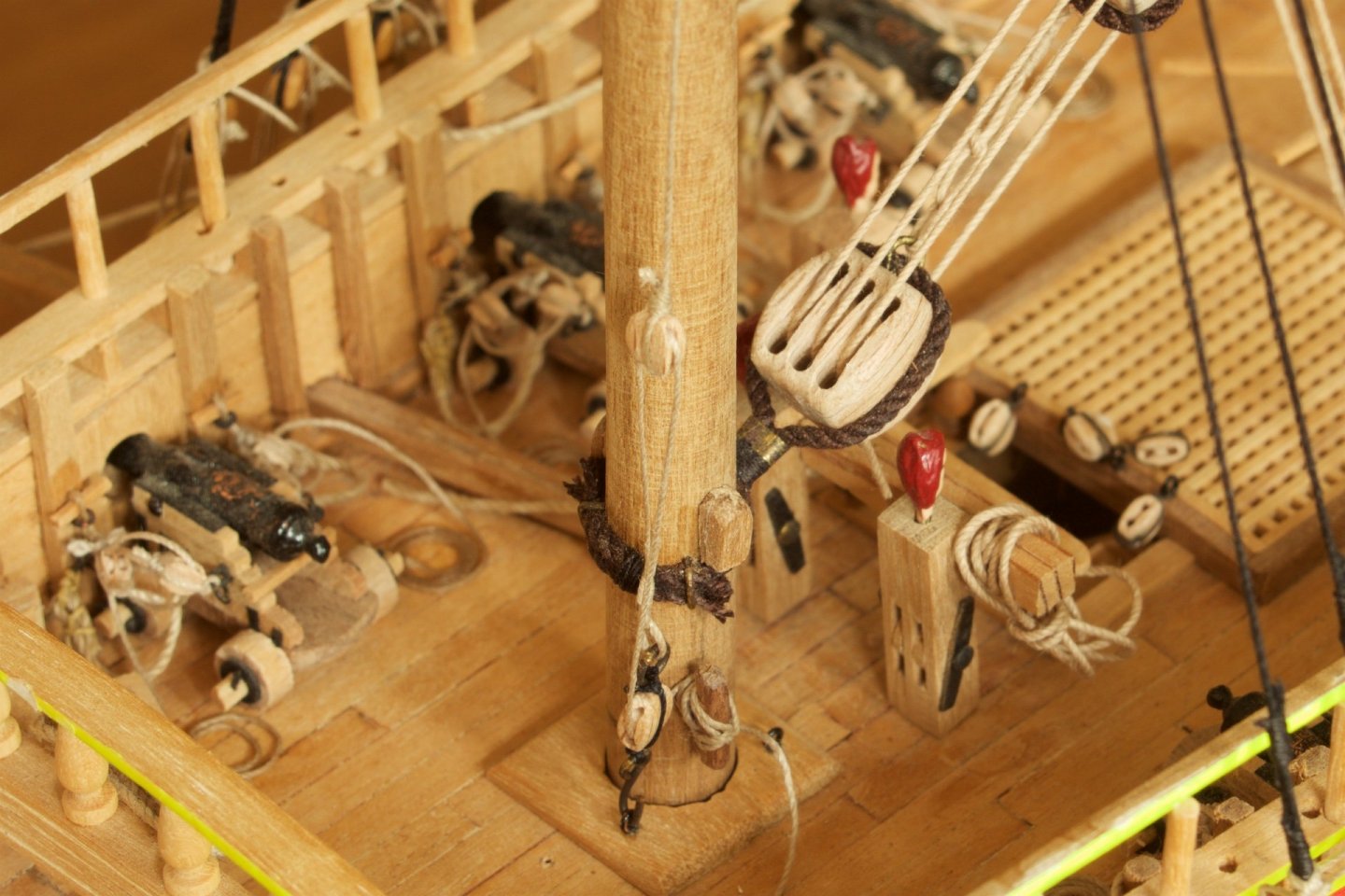
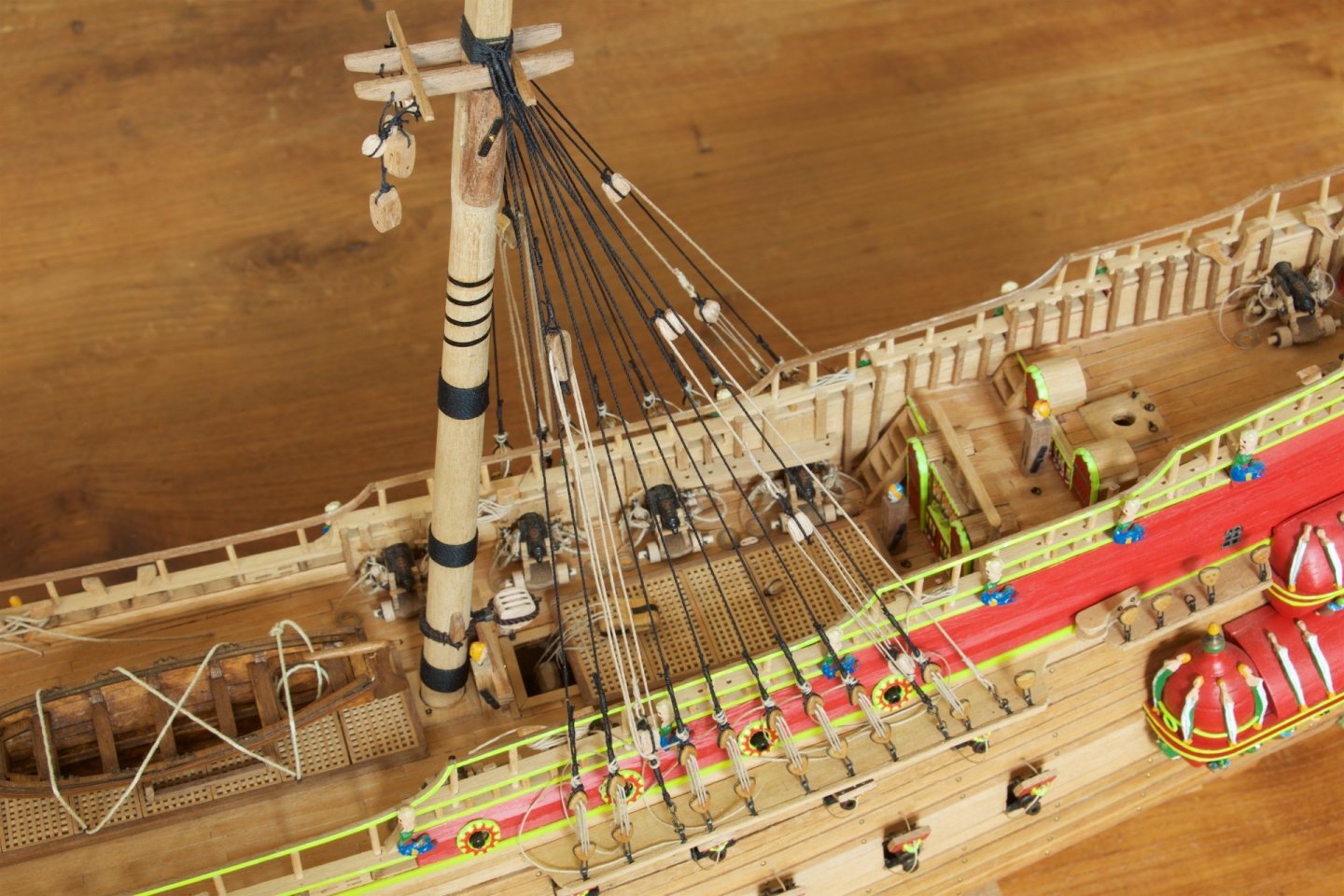
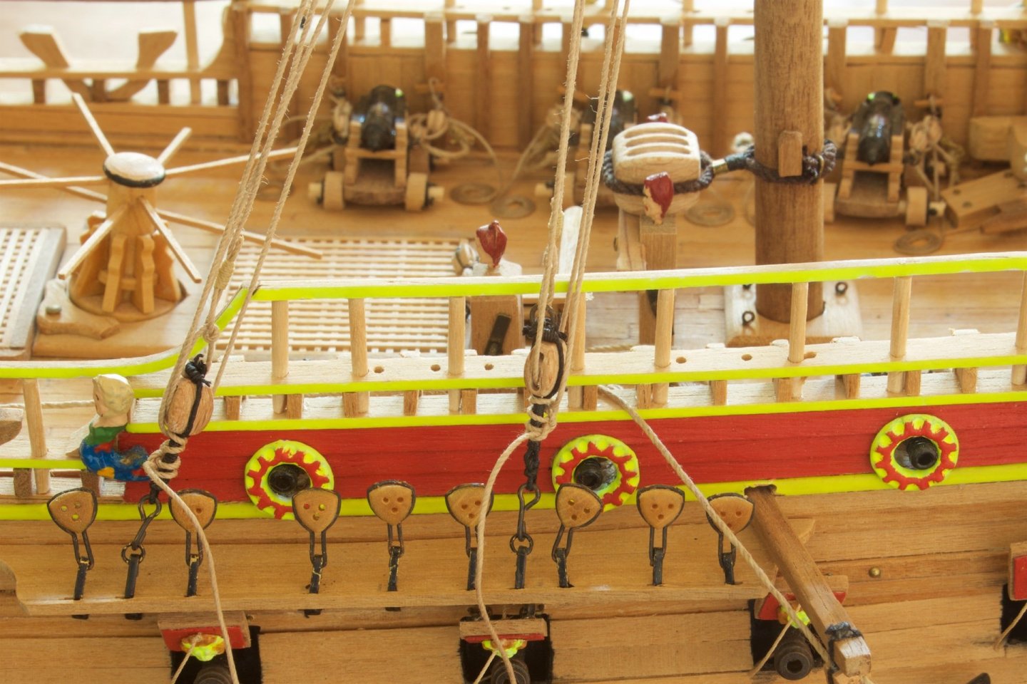
Before turning to standing rigging, I figured out that I still could to some tidying on the deck: The ropes of the cannons. Until now, I had the ropes more or less lying around on deck. I winded them up and glued them to the deck. For winding them, I used scotch tape. I fixed the rope with diluted wood glue, removed the tape and them glued the rope to the deck, again using diluted wood glue. Also, I made and installed the big block with which the main yard is belayed on the knight. This knight is below deck, and in my hull, there was no lower deck, so this sunken knight is glued directly to the interior frame.