


MD11pilot
-
Posts
110 -
Joined
-
Last visited
Reputation Activity
-

 MD11pilot got a reaction from STSCM in US Brig Syren by MD11pilot - Model Shipways - 1:64
Floyd, thanks for checking in. One of the first things I did to get started while waiting for my kit to arrive was to make some of the tools I found here in the Forums. I thought your idea for the planking clips was brilliant so I made up a bunch of them. It wont be long now before I can put them to use.
-
 MD11pilot got a reaction from Nirvana in US Brig Syren by Gahm - Model Shipways
Thomas, I'd be very interested to know how you thinned the horse shoe hinges. Dremel?
-
 MD11pilot got a reaction from fatih79 in US Brig Syren by MD11pilot - Model Shipways - 1:64
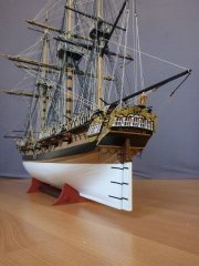
Making a little progress after getting back in town from a trip.
After attaching the keel and knees and letting the whole thing sit in the DeskMate for a couple of days, I was pleasantly surprised to see that the BF warp was completely gone.
Now time to add the bulkheads. I found one that was missing a sizable portion of the middle ply and the bulwark extension was hanging by just a thread of the outer ply. The picture is not so good, but you get the idea....
What to do, what to do? I braced the bulkhead and shot it full of expanding foam. After it cured, I carved off the excess foam and hardened the exposed surface of the foam with some glue. Came out pretty good I think. Was a lot easier than trying to carve wood to fit exactly in the hole.
Gluing in the bulkheads trying to be very precise with alignment....
It is no secret that the bulwark extensions on the bulkheads are fragile. But, in my kit, they were extra flimsy. I think the laser cutter was set too hot. Instead of making a nice little line on the surface of the wood, the reference lines burned thru the first ply and, in some cases, half way thru the center core. You can see how that would make them even easier to break than normal. I think I probably broke off half of them at one point or another. If you're getting ready to start your own Syren, you may want to dab some CA on these reference marks before you remove the bulkheads from the plywood sheets.
Has anyone else had this problem, or was I just the lucky one?
Out into the garage for the next step. Going to make lots of sawdust cutting and fitting the filler blocks.
Used balsa filler blocks to stiffen things up. Shaped and sanded the filler blocks to match the bulkheads.
Used a drum sander on a drill press to do the initial shaping/faring of the bulkheads.
Back inside to start working on the gun port framing. Used a batten and the gun port template to find a nice line across the hull. Turns out the reference lines on my kit were dang close. My line never varied by more than 1/32" from the reference marks. This step is just a lot of cutting, trimming, sanding, and gluing. Kind of relaxing. I found that Binder clips really helped with the sills. After dry fitting, the binder clips make a nice little shelf to sit the sill on when gluing it in and help to keep the sills nice and level.
To make it easier to install the lintels, I made little 15/32" spacers.
Now I didn't have to worry about measuring anything. Just sit the lintels on the spacers for perfect parallel installation.
Now it's back out into the garage to sand the framing down to match the bulwarks....
-
MD11pilot got a reaction from fatih79 in US Brig Syren by MD11pilot - Model Shipways - 1:64
Hi all.
Yup, another Syren. It's popular for good reason - a quality kit, Chuck's detailed instruction set, lots of Forum support, and it's a gorgeous little ship.
This is my first ship model. Yes, I know, it's too ambitious for a first build. But I've been a hobbyist, woodworker, do-it-your-selfer all my life so I thought I'd dive into the deep end. If I want to learn the entire skill set needed for my ultimate dream boat, the Surprise, then I need to practice on a ship that has all the same elements.
Feel free to chime in if you see me heading in the wrong direction. I don't plan to stray from Chucks practicum, so hopefully I wont make any irreparable errors.
While waiting for the Syren to arrive, I set up shop in the basement using an old computer hutch as my work station. Gathered all my hobby tools and purchased a few more. Found some great ideas for planking clips on other folks logs, so I made some of those too.
The kit arrived in fine shape - good packaging by Model Expo.
Initial impressions very good. The hardware kit is very complete. Glad to see the bags of blocks/deadeyes - thought I was going to have to make all of 'em. Back in the day, I built RC airplanes just when laser cutting was coming on the scene. It has come a long way. The laser cut parts in this kit are very precise and crisp.
So after a cursory inventory of all the included parts and a day of reading through the manual it's finally time to start making dust......
Eric
-
 MD11pilot got a reaction from kier in US Brig Syren by MD11pilot - Model Shipways - 1:64
Chapter one:
Clamped the BF into a desktop "Workmate" to straighten a slight warp. Soaked and formed the rabbet strip. Glued it on the next day. I'm using "Gorilla" brand wood glue. I like it. It "grabs" rapidly and is tough stuff.
Cut in the taper to the rabbet. It gets interesting at the aft end where the taper area is large - the grain of the different layers of ply want to fight your blade. But with a combination of a wide blade X-acto, a chisel, and sandpaper, I got 'er done.
Tapered the fore end of the stem. Added the stem knee and keel as one step. I purchased a small bucket of assorted binder clips. Glad I did. I'm finding them very useful.
-
 MD11pilot got a reaction from scasey88 in US Brig Syren by MD11pilot - Model Shipways - 1:64
I didn't want to be excessive with the treenaiing so I just used the bulkhead lines established with the butt joints.
-
MD11pilot got a reaction from scasey88 in US Brig Syren by MD11pilot - Model Shipways - 1:64
I chose to do my deck in a "3 butt shift" pattern keeping all my joints on top of bulkheads. For me, this adds enough artistic appeal, while keeping the difficulty to a minimum.
The idea of joggling into the margin plank was intimidating, but I have to keep reminding myself that this project is supposed to teach me all the all the skills I will need on other projects.
I used full width planks from bow to stern instead of tapering. I do like the tapered deck planks others have used, but at my skill level I opted to joggle full-width planks fore and aft.
As Sal suggested in his log, i laid in the first 3 planks on either side of the center line with no butts. Most of these planks will be covered in deck furnishings so the effort would be wasted. Also, applying these planks as full length pieces gave nice straight lines to work out from.
I used the #2 pencil method of simulating the caulking.
The first, full length planks go in….
-
 MD11pilot reacted to NenadM in Licorne 1755 by mtaylor - 3/16" scale - French Frigate - from Hahn plans - Version 2.0 - TERMINATED
I hope your Admiral is well.
There will be time for model
All the best
-
 MD11pilot got a reaction from _SalD_ in US Brig Syren by _SalD_ – FINISHED - 3/16" scale
Really enjoying your build Sal. Getting many great ideas for my project.
-
 MD11pilot got a reaction from Elijah in US Brig Syren by _SalD_ – FINISHED - 3/16" scale
Really enjoying your build Sal. Getting many great ideas for my project.
-
 MD11pilot got a reaction from Canute in US Brig Syren by _SalD_ – FINISHED - 3/16" scale
Really enjoying your build Sal. Getting many great ideas for my project.
-
 MD11pilot got a reaction from GLakie in US Brig Syren by _SalD_ – FINISHED - 3/16" scale
Really enjoying your build Sal. Getting many great ideas for my project.
-
MD11pilot reacted to _SalD_ in US Brig Syren by _SalD_ – FINISHED - 3/16" scale
Bitts, bitts and more bitts. The gallow bitts were straight forward and made per the instructions. The posts were pinned at both ends to help position them on the deck and to provide additional strength.
Riding bitts and fore bitts
The galley stack was made from 1/8” diameter brass pipe. I still need to work on my soldering technique as I ended up filling off more solder than what’s needed. The handles are made from 26 gauge wire and were glued (CA) into holes drilled on each side. It was then given three coats of black paint.
The bowsprit bitts were made per the manual except for the cross piece. I believe there is a typo for its size. The manual shows it to be 1/16” x 1/16” but on the drawing it scales off as 3/32” x 1/8”. I used the drawing dimensions. I didn’t glue this piece to the deck yet and I left out the packing pieces between the posts for now. I'm waiting until I get to the bowsprit mast to make sure everything fits before I secure it to the deck.
The last thing done was to set all the eye bolts and split rings for the carronade in-hauls. The in-hauls were positioned directly behind the carronades with the extra rings placed mid way between the in-hauls.
-
MD11pilot reacted to _SalD_ in US Brig Syren by _SalD_ – FINISHED - 3/16" scale
Chapter thirteen started off easy enough by making the two raised deck sections at the fore and main masts. I just added some small strips to finish off the edges. I’ll enlarge the mast holes later.
Then I moved onto the main fife rail. You know, Chuck seems like a really nice guy but then he goes and tells you to take these flimsy, 1/32” thick laser cut pieces of basswood, with holes in them no less, and round off their edges!!! Well all I can say is thank God for scotch. Maybe I just didn’t have a good method for doing this but these pieces are a true test of your patience. I walked away from these parts three or four times after breaking and gluing them back together the same amount of times. For those that are working on this model take your time and use very soft hands as you work on these parts. I finally finished both rail pieces and glued them together. They’re not the best but I ran out of scotch, only kidding, I have plenty.
For the legs I chucked a 1/16” dowel into my drill press and turned them to resemble the draw as close as possible. After cutting them to length I inserted pins into each end to help secure them in place. The parts were then stained and assembled. Belaying pins were added prior to mounting on the model.
-
MD11pilot reacted to _SalD_ in US Brig Syren by _SalD_ – FINISHED - 3/16" scale
First I would like to thank everyone for all the 'likes' and for the kind words of encouragement, they're much appreciated.
Continuing with the aft deck fixtures I made the water pumps from some brass and copper tubing I had. The pieces were soldered together and given a coat of paint. It’s amazing what a couple of coats of black paint will cover up. The parts were then assembled as described in the instructions.
The aft cannons were set in place and rigged pretty much the same as the carronades, just not as many.
The tiller was made as shown in the instructions and as I was thinking about how to attach the split rings to it I remembered that I had won a serving tool in a raffle at the Northeast Ship Model Conference last April. So I tried my hand at serving some rope to lash the rings to the end of the tiller. It took a few attempts but I finally got the hang of it.
Finally I rigged the ships steering mechanism. My final configuration is a conglomeration (say that five times fast) of a number of layouts I studied on this forum. I thought that the position (angle) of the line from the tiller to the bulwark would work more efficiently if it was more in line with the arc the tiller would travel in instead of being perpendicular to it. To accomplish this instead of moving the eye bolts on the bulwarks farther aft which would have crowded the aft cannons, I made the tiller a little longer. I also added two blocks at the base of the ship’s wheel to keep the line lower to the deck. To give myself a little more room to install these blocks I decided to reposition the wheel to the outside of the support legs. I’m not sure if this is historically correct but it made rigging the line easier and I thought it would give my helmsmen a little more room to steer. I also had to remove the binnacle that was already installed because the spacing between the wheel, binnacle and companionway didn’t look right. Before reinstalling the binnacle I decided to add a compass in it.
-
MD11pilot reacted to AlexBaranov in HMS Cumberland 1774 by AlexBaranov - FINISHED - 1:36
Finally, a friend of mine put together a movie.
See here:
-
MD11pilot reacted to Tadeusz43 in Art of period shipbuilding
Hi,
I collect photos concerning hull structure and construction from presently
constructed replicas of Dutch ships De Delft ( in Rotterdam) and De 7 Provincien ( Batavia werf in Lelystad).
They show details of the construction of the hull
.
Tadeusz
De Delft
Spring 2003
Keel and stern post
Frame details in workshop. On the floor are drawn shapes of frames in scale 1:1.
Large scale structural model for final checking of frame shapes
Frame details machining
August 2015
-
MD11pilot reacted to Tadeusz43 in Art of period shipbuilding
Hi,
Rigging blocks.
In ancient times and middle ages blocks were handmade by craftsmen using simple tools.
The development of shipbuilding resulted in a significant increase in the number of blocks needed for rigging and their types variety.
A typical ship of the line needed about 1000 blocks of different sizes.
In 1802 Marc Isambard Brunel proposed to the Admiralty a system of making blocks using machinery he had patented and in August 1802 he was authorized by the Admiralty to proceed.
There were 22 types of machines and their total number was 45. The machines were driven by two 22.4 kW (30 hp) steam engines.
The machines included circular saws, pin turning machines and morticing machines.
With these machines 10 men could produce as many blocks as 110 skilled craftsmen.
Production finally stopping in the 1960s.
Foto 1-3 Blocks from Ancients wrecks and block making craftsman. Maritime Museum in Gdańsk.
Foto 4 Block making craftsman. Maritime Museum in Karlskrona.
Foto 5 Blocks from Mary Rose . Historic Dockyards Portsmouth.
Foto 6,7 Blocks on replicas of medieval ships.
Drwg. 8-10 Period ship blocks and tools for block making.
Foto 11 Block making . Maritime Museum in Karlskrona.
Foto 12,13 Brunel's factory and machines. Historic Dockyards Portsmouth.
Foto 14 - 20 Blocks on Batavia replica in Lelystadt .
Tadeusz
-
MD11pilot reacted to Tadeusz43 in Art of period shipbuilding
Hi,
A very important piece of equipment of ships were ropes.
A large sailing ship rigging require approx. 16 km ropes of different diameters.
Ropes produced mainly from hemp fibers using ropewalk.
Foto 1,2 Ropes in HMS Victory hold
Foto 3,4 The Ropewalk in Karlskrona dating from 1692, the rope factory terminated production in 1960.
With a length of some 300 metres (980 ft), the Ropewalk is Sweden's longest wooden building.
Foto 5-7 Rigging worshop in Maritime Museum in Karlskrona
Foto 8 Rope making tools in Maritime Museum in Gdańsk
Foto 9 Rope making tools in Historic Dockyards in Portsmouth (UK)
Foto 10 Big ropewalk model in Maritime Museum in Karlskrona
Foto 11-15 Rope making tools in Maritime Museum in Gdańsk.
Hemp fiber was cleaned by combing with iron hedgehog.
Then it were twisted in to the cords using reels.
Finaly on ropewalk cords was twisted in to the ropes.
Foto 16 Rigging worshop in Batavia Shipyard in Leystadt
Tadeusz
-
MD11pilot reacted to Tadeusz43 in Art of period shipbuilding
Hi,
The wood used in the construction of ships in Europe, it was mainly oak.
For the construction of HMS Victory used more than 6000 trees.
In ancient times, the tree trunks were cleaved to the corresponding planks then began to use handsaws a technological breakthrough was the use of sawmill powered by a water wheel or windmills.
Naturally curved tree trunks was used for ship construction elements.
Sometimes, even the deformed growing tree to obtain in the future desired shape (something like bonsai)
Strips on the hull were bent over the open fire.
Foto 1-4 Vasa shipyard (Vasa Museum in Stockholm)
Foto 5 Sawmill with wind power (Maritime museum in Karlskrona , Sweden)
Foto 6-10 Viking boats shipyard ( Roskilde, Denmark)
Foto 11 Batavia - sample of knee shaped bu nature
Foto 12-14 Nature shaped elements of shps (Maritime Museum in Gdańsk)
Foto 15-16 Shipbuilding forest on Baltic coast in Poland
Foto 17-18 Shipwright's tools
Tadeusz
-
MD11pilot reacted to Tadeusz43 in Art of period shipbuilding
Hi,
Some of these shipyards have survived and are still working.
Foto 1,2 Arsenale in Venice Italy - still on duty
Foto 3-5 Darsenas i Barcelone - now Martime Museum
Foto 6-7 Karlskrona Sweden
Foto 8-9 Historic Dockyards in Portsmouth UK
-
MD11pilot reacted to Tadeusz43 in Art of period shipbuilding
Hi,
Art of shipbuilding.
Due to the lack of scientific methods of calculation and design of ships
ship building in the old days was a kind of art and everything depended on the experience of employee master of shipbuilding.
Gathered here from my archive of photos from various museums showing how ships were built centuries ago.
A few photos from the net is because old shipyards are still in the Navy possession or a ban on photographing in some museums.
Project.
Construction of a new ship ordered by the King was preceded by a performance of the model to the Admiralty can assess whether the project meets its requirements. Many of such models have survived to our time, they show the details of construction of the hull, we call it The Admiralty Models.
Because in those days there were no scientific method stability calculations all based on the experience of masters of shipbuilding.
Admiralty models
Assembly of Admiralty
Tadeusz
-
-
MD11pilot reacted to Redshirt in How to get close fitting "connections"
OK, the threadtitle might be a bit stupid but im having a real problem here.
Im currently trying to cut and assemble the various parts of a ship's keel but im constantly frustrated by the low accuracy of my work. I tried cutting/sawing as accurately as possible but with little success. I tried leaving something "extra" to later sand it to shape with the Dremel but this isn't working either. Especialy conkave surfaces and these damnable scarph joints (can't cut them with the tablesaw since the lower side of the round blade of course cuts a bit further than the upper side) give me trouble so im asking for advice.
How do you people manage such tight connections between the various parts of your ships's keel/stem/sternparts.
-
MD11pilot reacted to Erebus and Terror in HMS Terror by Erebus and Terror - FINISHED - Scale 1:48 - POB - as fitted for polar service in 1845
ASSEMBLING TERROR’S STERN
(Or, finally some sawdust!!!)
I haven't posted an update regarding my model in several months. While I've kept busy with side projects, the real reason for my delay is that I had reached an impasse with Terror’s stern.
As I've discussed in previous posts, the sterns of Franklin’s ships were modified in 1845 to accommodate a new auxiliary screw propulsion system – to be used as a time saving device “providing the wind should prove contrary or a dead calm”. There are two sources of data on these modifications: Oliver Lang’s original design plan, and its counterpart, a contemporary model of the design. I had purchased full resolution copies of the plan many months ago, but unfortunately Lang did not include a cross section in his draught. That information could only be gleaned from the contemporary model held at the National Maritime Museum’s storage facility in Chatham.
The contemporary model of Oliver Lang's 1845 design.
National Maritime Museum, Greenwich, London (SLR2253 [L2251-001]).
Used under Creative Commons Attribution-Non-Commercial-ShareAlike (CC BY-NC-SA) license
Fortunately, I recently had an opportunity to visit the Chatham model ship facility. Assisted by the expert curators, I was able to study the stern model in detail. It is quite unique, being constructed using a series of carved blocks arranged to conform to the position of major structural and engineering elements of Lang’s design. The information I gathered has allowed me to complete my construction of the stern; below, I’ll reveal the new information I've learned from the contemporary model, while documenting my final assembly of Terror’s stern:
1) The propeller well used to raise and lower the screw was rectangular, almost square-sided, with the sternpost and rudderpost forming the fore and aft sides of the well, respectively. To accomplish this, thick timbers were bolted to the sides of the rudderpost and sternpost. The rudderpost bolsters were much more complex than I originally assumed and were each constructed of at least two pieces, with the lower portions tapering gently to the width of the rudderpost, following the lines of the body plan (see here for my original conceptualization of the design).
The stern pieces prior to assembly. The bolster on the left is the old design I intended to use,
which was incorrect.
The overkill method I used to glue the bolsters to the stern and rudderposts.
Thankfully this was just a dry-run (note the older bolster design).
The new bolster timbers glued on the rudderpost. Note the groove for the "Lihou" rudder on the
rudderpost. I may need to sand the bolsters somewhat to match the run of the planking as they
may be slightly oversized - but no by much.
Another angle showing the bolster timbers on the sternpost.
The NMM model shows that the bolsters on the rudderpost are
longer than those on the sternpost.
2) The rudderpost and sternpost were each tenoned into the keel extension, as was typical, but each was secured with a single bolt, which was not indicated on Lang’s plan.
Marking the precise position of the tenon bolts.
The bolts were simulated with 20 gauge copper wire, precisely the
same as that used on the keel scarphs.
3) The propeller well was framed on the port and starboard sides in three distinct sections. The upper section included stout rectangular framing fayed to the deck beams, which formed a ledge for a scuttle on the upper deck. Below this, the well was probably enclosed by watertight planking down to the height of the stern timbers. Because of the construction of the contemporary NMM model, such planking was not shown, but it is unlikely that solid timber pieces would have been used, as these aren’t shown in contemporary models.
The heavy framing used to form the top of the propeller well.
The upper part of these timbers formed a lip for a scuttle to the well.
Planking on the upper section of the well. I've estimated a width of 12 inches.
The actual width is unknown. Note that this section of the model will be covered
so I haven't simulated bolts or spikes here.
A view of the topside of the well. The upper pieces of the sternpost
and rudderpost bolsters will be trimmed at a later stage of the build,
but are useful for alignment at this stage.
4) A new section, clearly visible in the well of the model, started at the position of the stern timbers. This suggests the stern timbers were bolted to the sides of the rudderpost and sternposts to provide major structural support to the new rudderpost and well. This makes good sense, and Lang’s 1845 stern plan clearly shows the stern timbers as a major element of the design. In fact, these new timbers are substantially more robust than Terror’s original stern timbers, suggesting they were an integral part of the strength of the new structure. Again, this type of structure is supported by contemporary models.
The bottom portion of the framing planks were trimmed to match the run
of the stern timbers. Note the rabbet on the rudderpost on the right.
5) The lower section of the propeller well was composed of the second layer of hull planking where it ran aft, horizontally. Eventually, the run of the higher planks would have veered away from the straight-sided wall of the well. At this point, straight horizontal planking would have been used to frame the sides of the well. The position where this occurs is marked by a block seam on the contemporary NMM model.
Unfortunately, Lang’s contemporary model does not include any of the ironwork used to strengthen the stern, nor does it include the propeller rail/track mechanism. I've based these portions of the model on Lang’s plans and extensive research on other contemporary models and designs. This research is outlined in several blog posts (and here, here, and here).
Oliver Lag's stern design. Note the extensive ironwork and the propeller systems.
National Maritime Museum, Greenwich, London (ZAZ5683 [J1529]).
Used under Creative Commons Attribution-Non-Commercial-ShareAlike (CC BY-NC-SA) license.
The iron staple knee glued in place. The knee provided essential support for the rudderpost.
Mini-Crozier inspects the staple knee in dry dock.
Lang used iron strapping to further reinforce the stern structure. Here they are made from
chemically blackened copper.
Each strap was glued in place and then the bolt holes were drilled out by hand.
Bolts glued in place. These were simulated using blackened brass.
Another view of the completed iron work.
Mini-Crozier frets over the modifications.
The staple knee was protected by a fitted chock bolted to the keel section.
I carved this using a simple chisel blade.
The finished chock compared to the plans.
Image showing how the chock fits over the knee. Unfortunately it had to
be glued in place to permit the propeller rails/tracks to be installed.
At least I know the knee is there.
The chock glued in place.
The propeller was raised and lowered using rails or "tracks". These have been
modified slightly from my original versions based on new data. Copper bolts
were simulated using wire.
The rails glued in final position. Note the rabbet on the rudderpost
for the second layer of hull planking. The rabbet will be modified to
accommodate the precise run of planking when it is installed.
View of the rails installed on the sternpost.
View of the rails installed on the rudderpost.
Another view.
Wooden bolt plugs added to the chock. The bolts were "counterbored and plugged".
The staple knee was bolted to the rudderpost; these bolts were also counterbored
and plugged. I'm not entirely happy with the contrast here and may redo them at a later date.
The completed stern assembly.
Lowering the screw propeller in place (it raise and lowers - and the propeller spins).
The propeller in position. Unfortunately the angle of the photo makes it
look slightly crooked, but it is not - is spins freely, with very small
tolerances as shown on Lang's original plans.
A view from the stern.
Another angle showing how the propeller was seated.
Looking down the well from the position of the upper deck .
Mini-Crozier contemplates how the stern will fare in the ice.
How successful was Lang’s stern at protecting the ship from the pack ice? Parks Canada divers are assessing that currently, and with luck they’ll find the answers soon. We know from historical sources that the Admiralty was concerned about the strength of the design, and that while Lang believed the “sternposts” (sternposts and rudderposts) were as strong as those on other ships, he would not certify that the strength of the filling chocks was sufficient to protect the Erebus and Terror [4].
No matter how vulnerable it made the ship, we can suspect that Lang’s radical redesign also altered the sailing qualities of Terror. Contemporary sailing reports indicate that Vesuvius class bomb vessels were rather lumbering and could not carry sail well, and Ross reported that Terror was constantly falling behind Erebus during his Antarctic voyage, delaying and endangering the expedition.
Recently, Regina Koellner, assisted by William Battersby, transcribed a letter from Francis Crozier to his friend John Henderson, written shortly after the ships arrived at Whalefish Islands in Greenland. In the letter, Crozier provides a brief report of Terror’s sailing qualities: "Our steering is decidedly improved by the alterations on the counter we now sail much more evenly with Erebus which is advantageous to us in many ways." I suspect that the effective lengthening of the keel to accommodate the propeller allowed Terror to sail closer to the wind, finally permitting her to keep up with the more nimble Erebus. It seems the final conversion of Terror to screw propulsion made her a more capable vessel under sail, an irony certainly not lost on Crozier.