DONATION DRIVE - SUPPORT MSW - DO YOUR PART TO KEEP THIS GREAT FORUM GOING!
×


JSGerson
-
Posts
2,633 -
Joined
-
Last visited
Content Type
Profiles
Forums
Gallery
Events
Everything posted by JSGerson
-
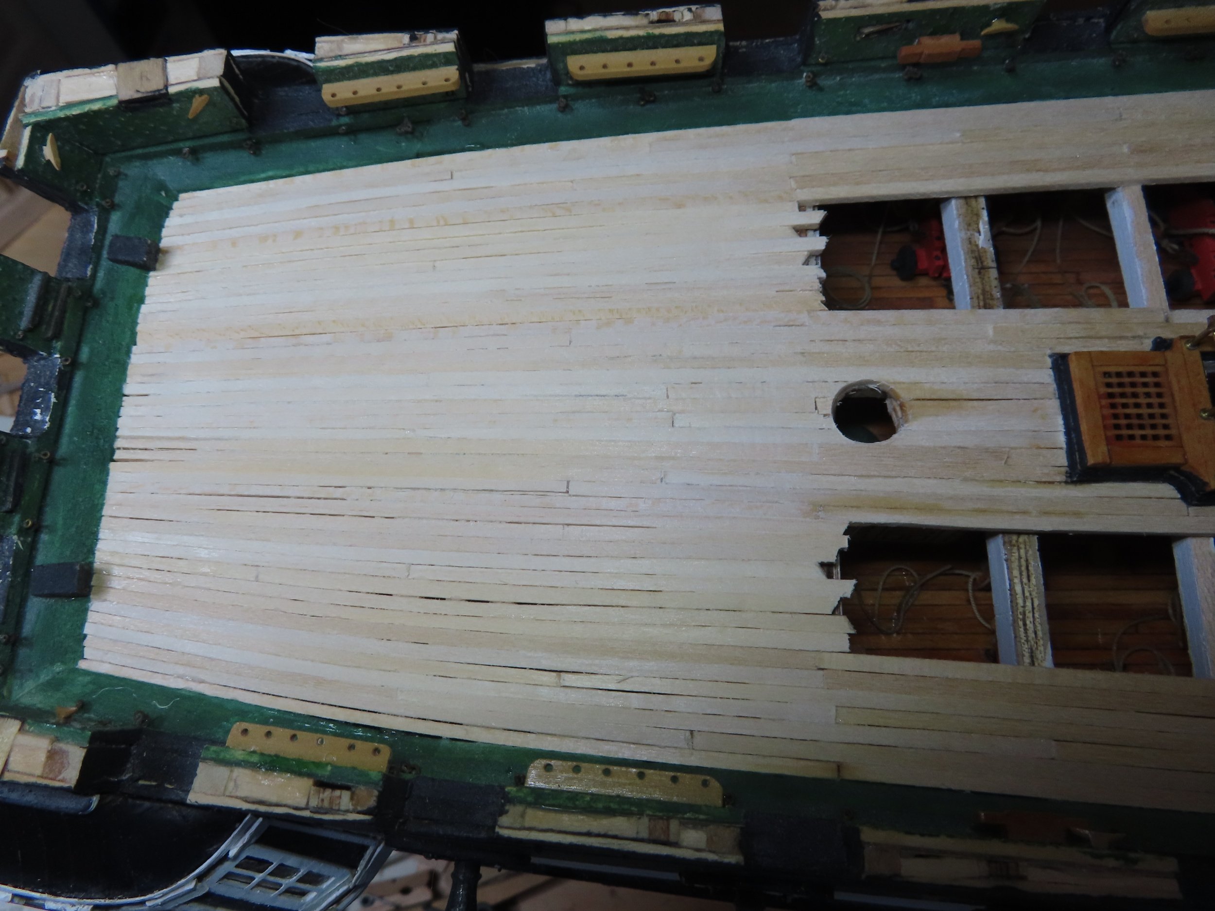
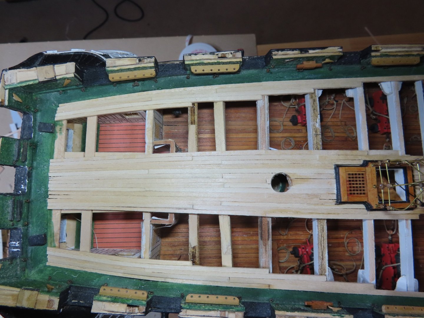
 Unlike the stern, the 3/32” x 1/32” planks are not tapered as they approach the bow. The planks remain straight and those bordering the waterways were customed fitted into the curving bow. I planked the bow in the same manner as I did the stern, from the waterways inward and from the center outward. It did not surprise me, as the planking approached each other and as open space narrowed, I had to taper the widths a bit of some of the planks to ensure a proper fit when they merged.
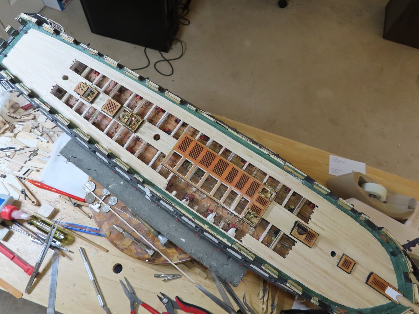


-
That was beautifully done! Jon
-
The wheels look like a fun little project, so I'm saving them as my incentive and "reward" to complete the spar decking and the carronades first. I've also got to fabricate the spar capstan too. Jon
-
As you may know from reading my blog, I purchased two Syren ship's wheels a number of years ago in anticipation to replacing the kit's. Those kit metal wheels you painted look really good. What technique and color did you use? It's nice to know that if I screw up, I have a fall back option. I still have a ways to go before I can start assembling them, so it looks like I'll be following your lead. Jon
-
Out of curiosity, why did you cut the filler block such you had to mill out the notches in the top half blocks? If you had made the top half blocks thinner and the bottom half blocks thicker, you could have used your scroll saw to cut out the notches. The end product would have been identical, just simpler. In any case, you did a nice job. Jon
-
Beautiful!! Jon
-
Looking good. Gregg Jon
-
That's one handsome looking hull Jon
-
Good choices Jon
-
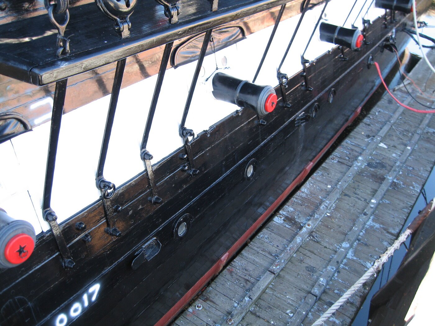
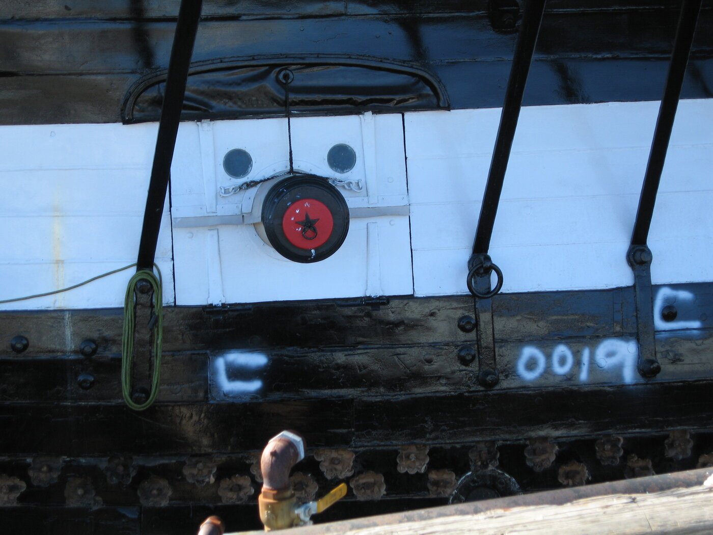
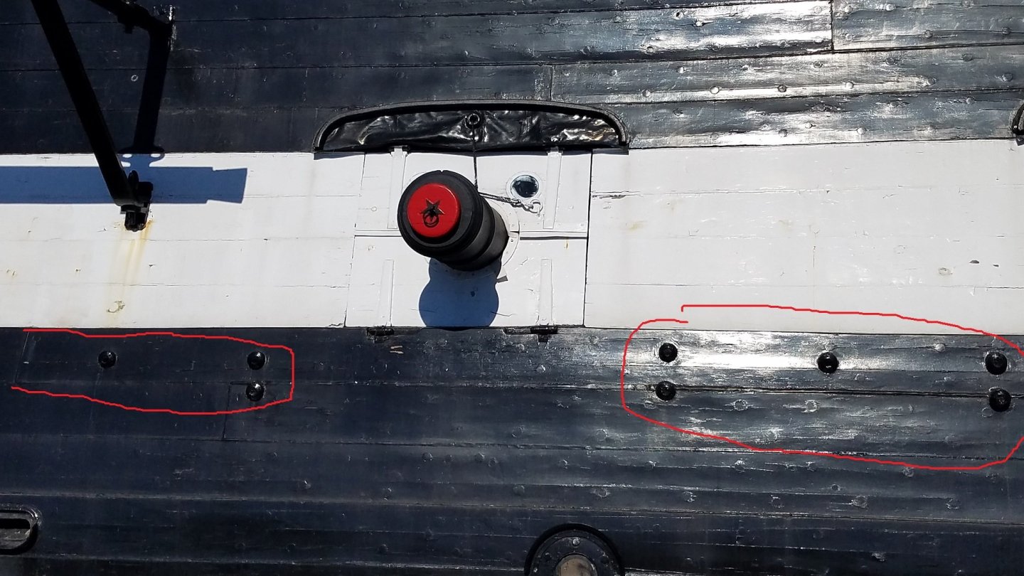
Here are a few images of the eyebrows. I have not seen anywhere what they are made of, but they look either like painted canvas or copper plate for water proofing. That being said, the flat wrinkly part looks very thin while the lip bordering it is just an inch or two. Jon
-
Let’s go back to the basics. You are building a model of a real ship albeit stylized with your choice of color palette. The real ship is black with a white gun stripe. It also has “eyebrows” and gun port hinges. Your model is stained dark where the actual ship is black, light-colored wood, where it is white and has brass for all the metal parts. the The "eyebrows" on the real ship are black and the hinges are painted white. Therefore, following that color palette, the color for the “eyebrows should be included on the model and match the dark stained wood, and the hinges should be brass. Granted, there will not be any contrast between the “eyebrows” and the hull, but neither is there any on the real ship. If you are not consistent, I fear the model will lose some of its handsome character. Just my personal thoughts. Jon
-
Where did I state 10 days? I'll correct the error if I can. It was 10 months. Jon
-
Knowing how you like to say "oooh shiny!"😲 I figure you'll pick the brass. Whatever your choice, either one works well. Jon
-
It's frustrating, I know. All I can tell you is to review as many other builds out there and try to follow one that you like best. I don't think anyone has done the rails and trailboards the same way twice. Just a forewarning, you are going to have just as must "fun" or more with the quarter galley windows. The laser cut window frames supplied with the kit are useless as they are the foreshortened shape shown in the plan elevation view and don't reflect their actual shapes. And no, neither the kit nor any other sources I checked, shows their actual shapes. But if were easy, it would be so much fun!😆 Jon
-
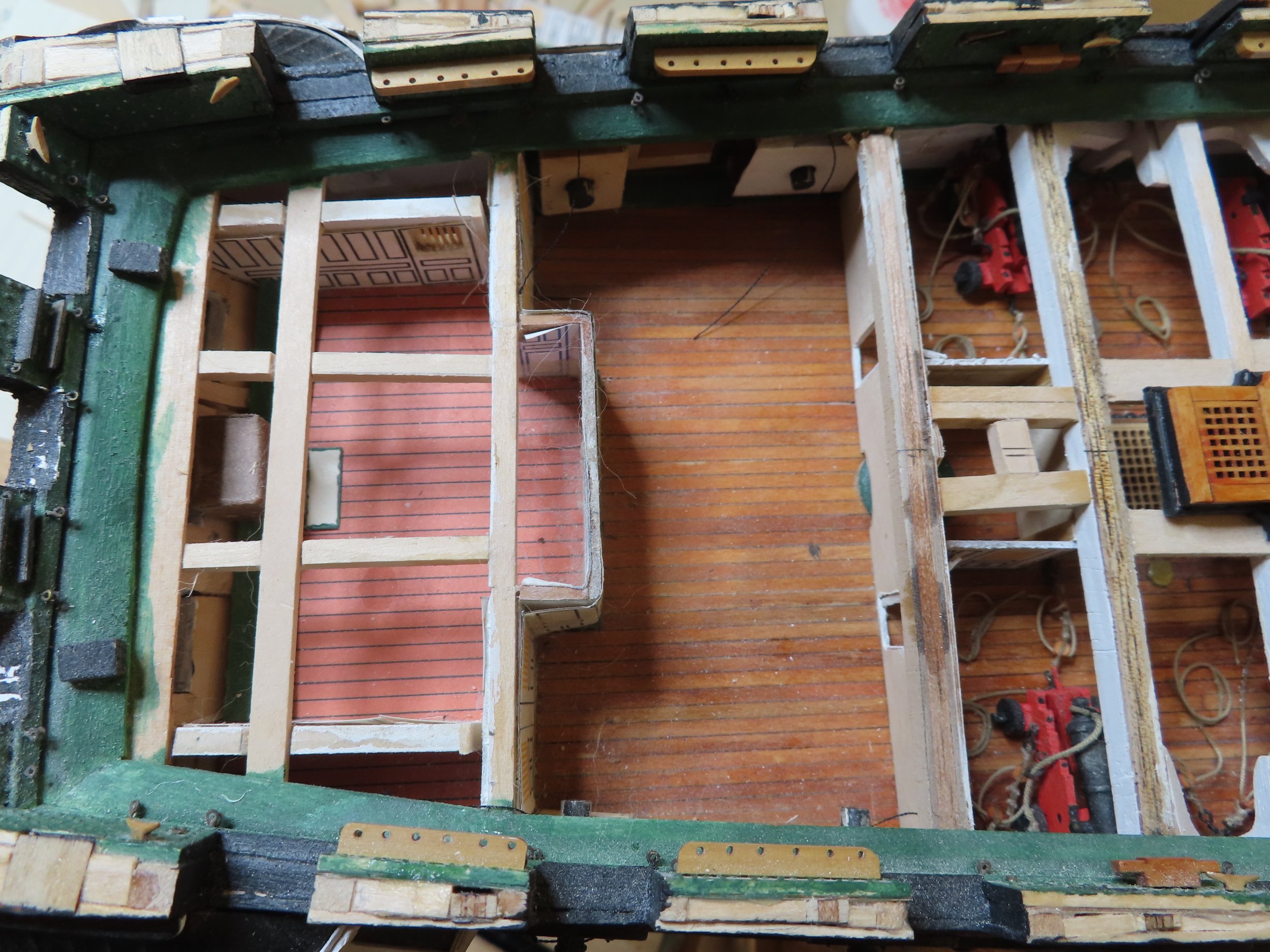
Peter, raggedness of the planks is deliberate. If I made clean cuts, it may look like the clean cut openings were part of the design of the ship to an ignorant (read "lack of knowledge," not "intelligence") layman. By making them ragged, I wanted to give the illusion that the deck was broken open to see inside. You may also seen that I did the same thing with the cut beams on the starboard side waist. Gregg, the jury is still out as to whether or not I fabricate the carriages. My heart says make the wooden carriages, but the practical side of me just paint the carronade and maybe get a better effect. I think I have one or two extra carronade to experiment with. In either case I still have to rig them. Maybe one or the other is easier to do, I don't know yet. Jon
-
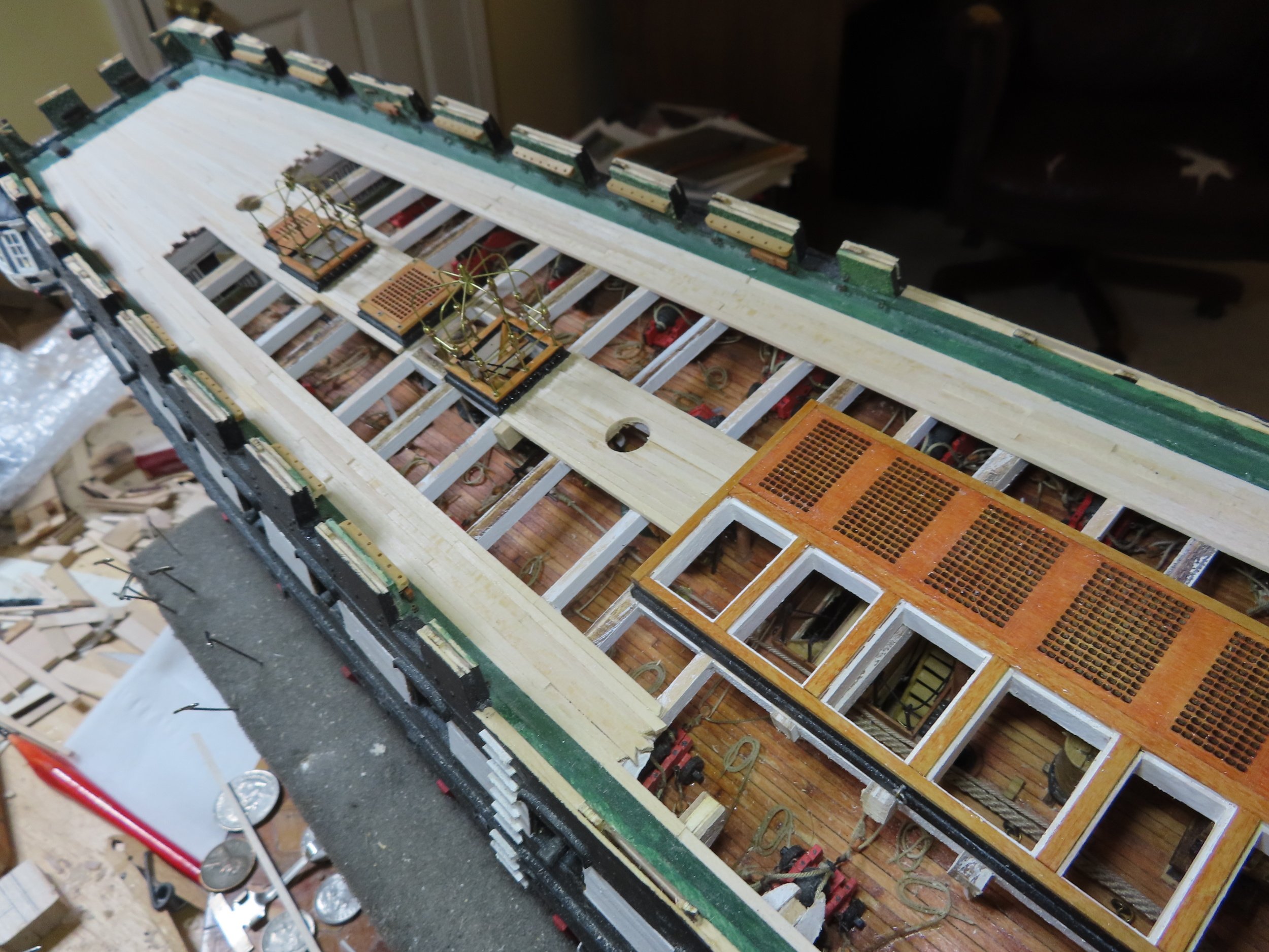
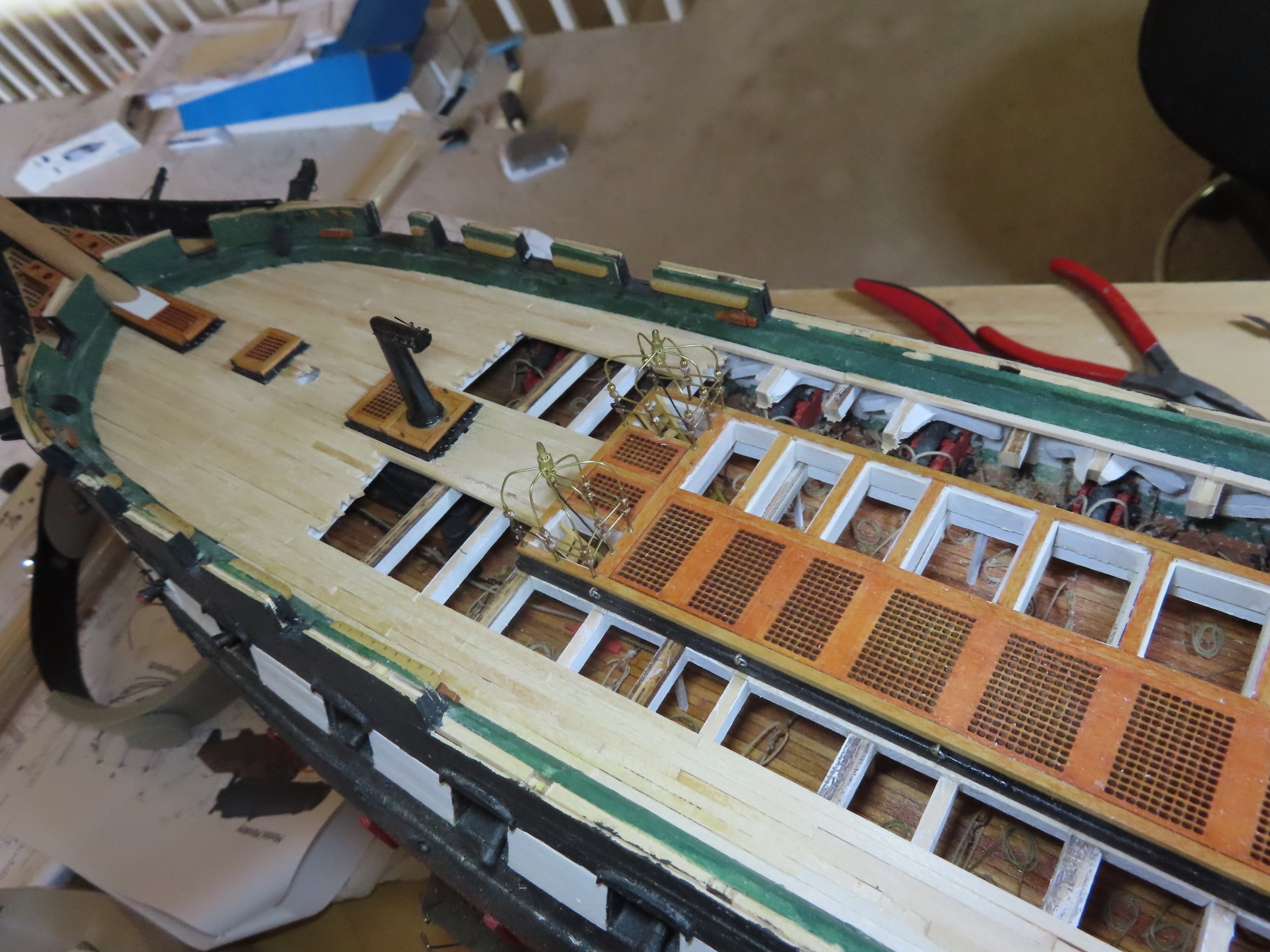
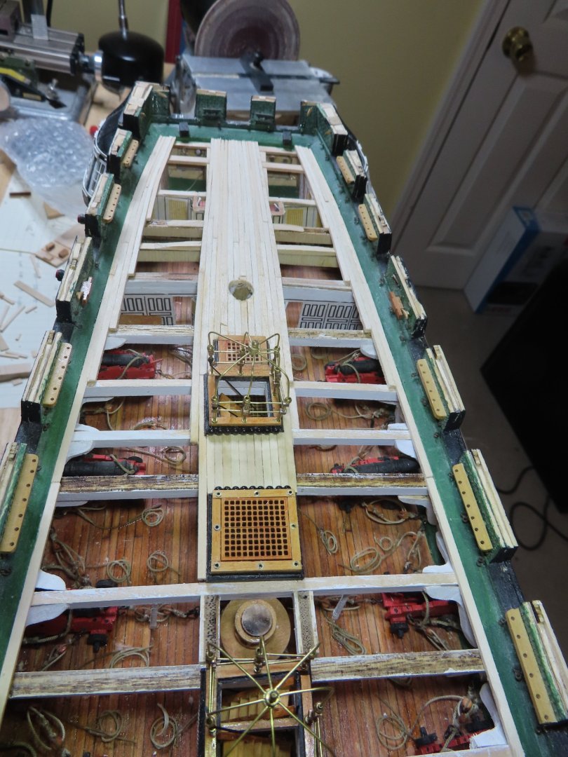
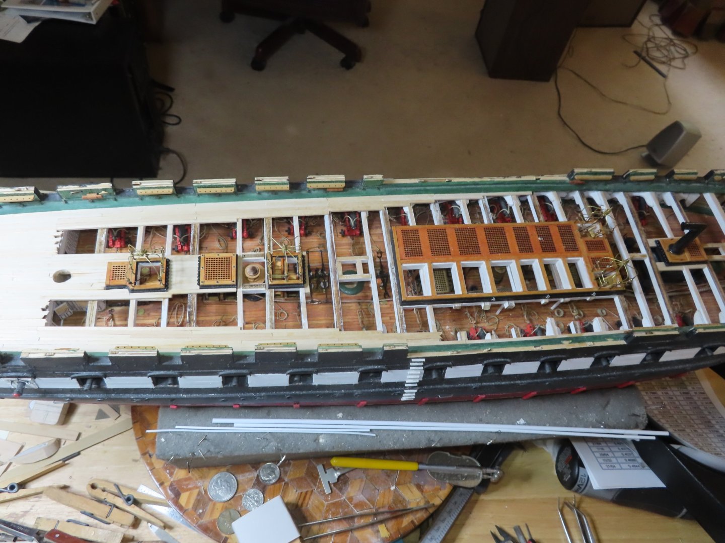
I started planking the center of the spar deck, starting from the capstan opening and working my way back to the stern until it filled in to the width of the hatchways. Then I applied the planks against the waterways, starting from the stern and working forward. The stern was fully planked to just forward of the captain’s dining area, then the plank voids will allow the gun deck to be visible. The forward areas are yet to be planked.

-
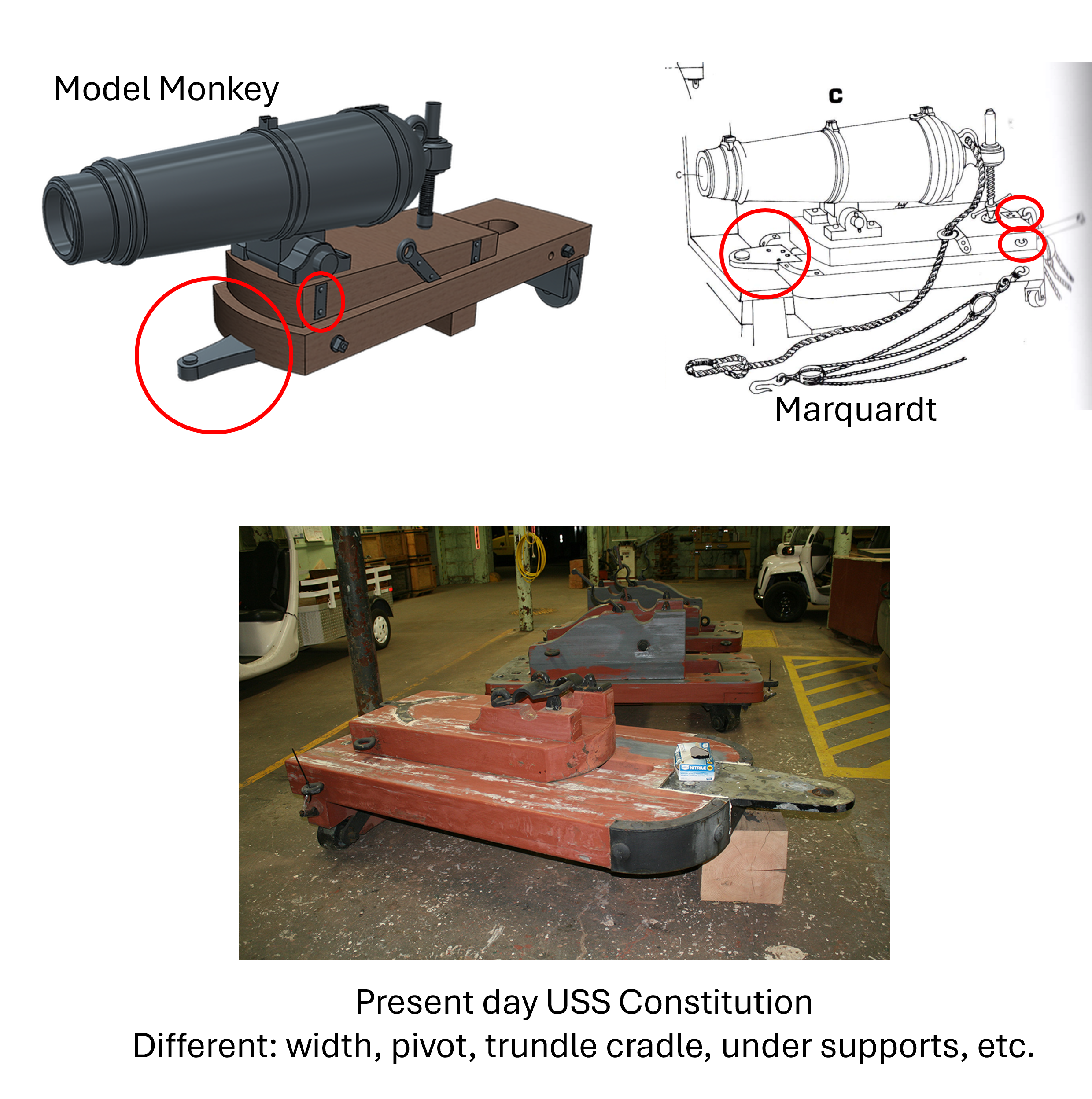
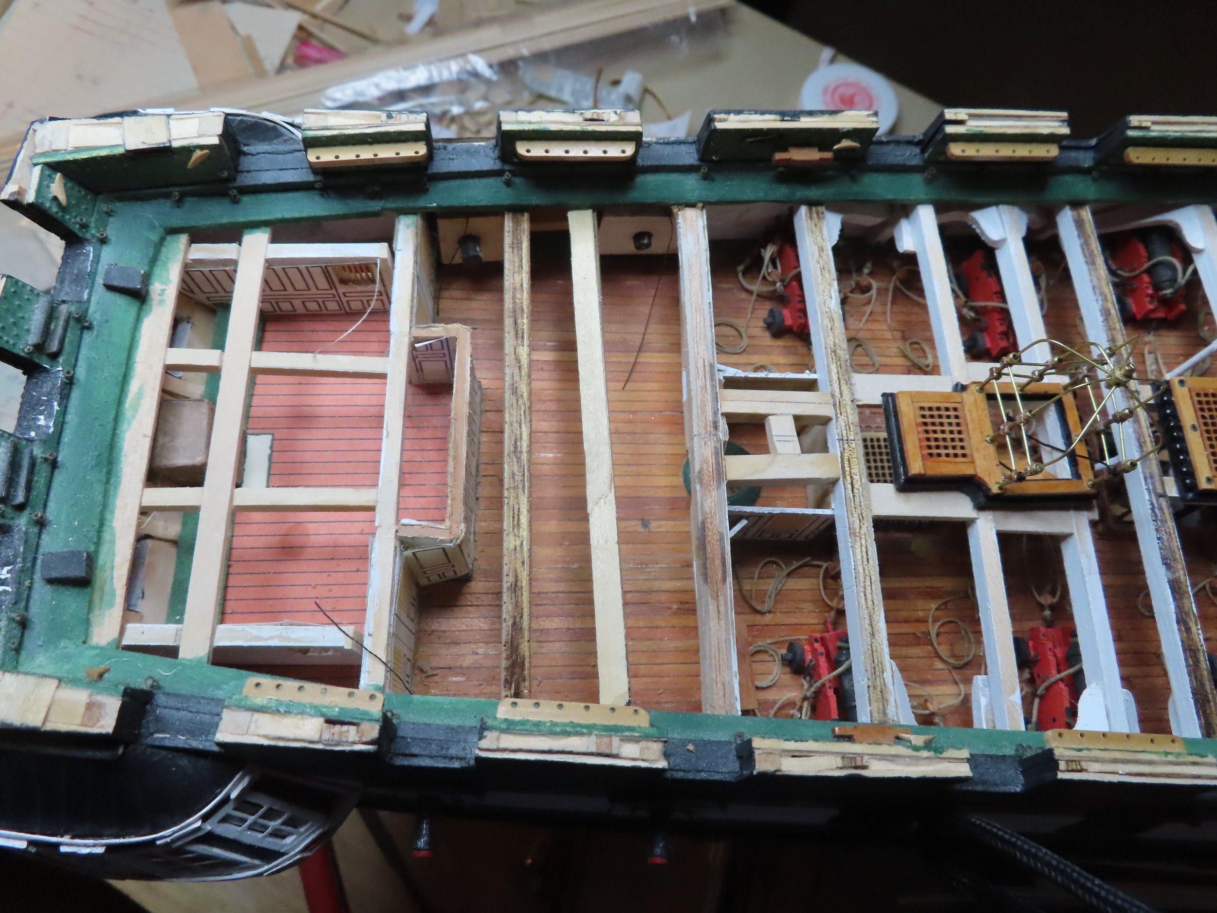
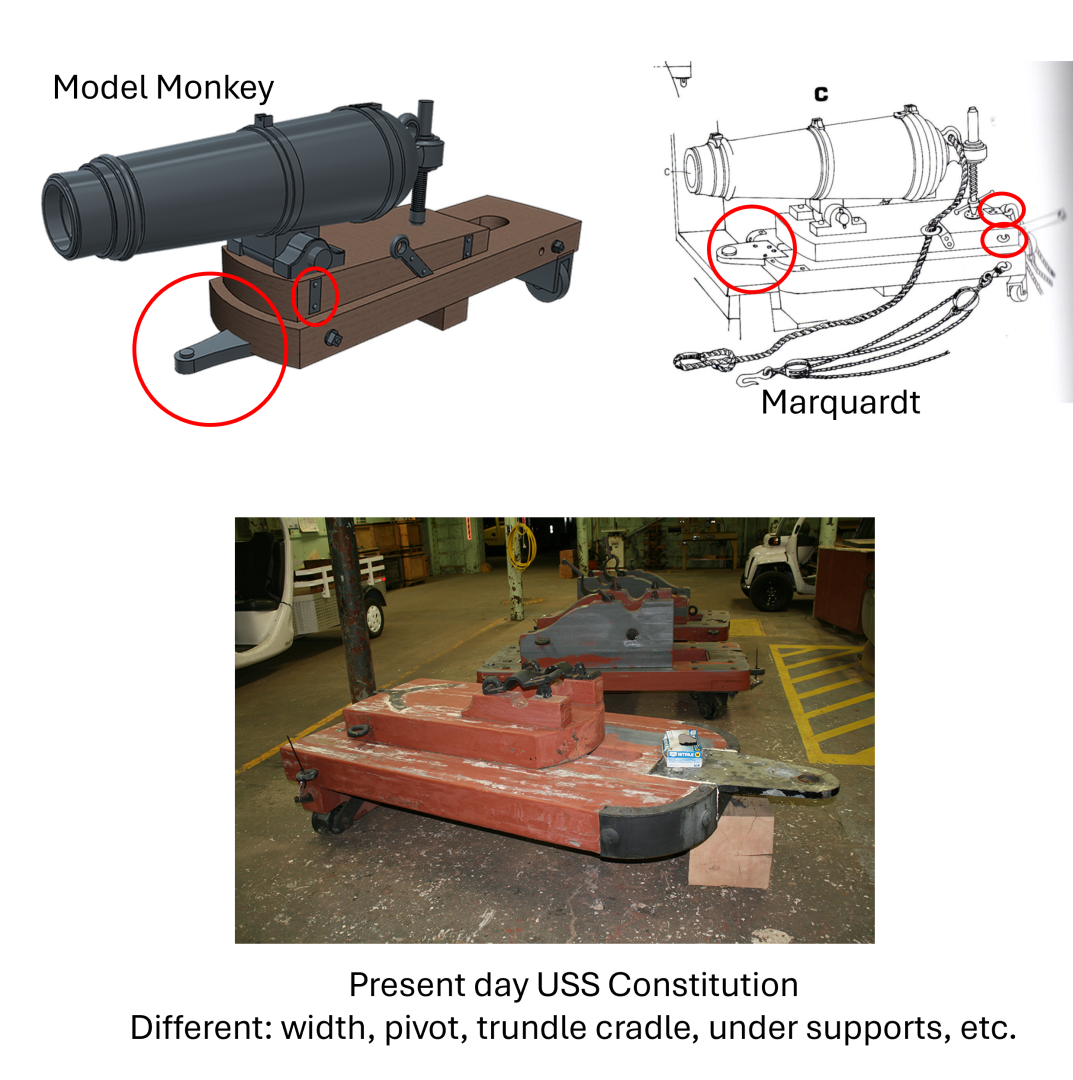
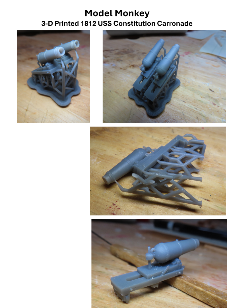
The MS plans show the planks tapering towards the stern on the spar deck, with the planks from 3/32” wide to the transom at 1/16” wide. The model’s far aft area of the stern is to be fully planked. I started the taper of the planks per the practicum, from the most aft hatchway. Unlike the gun deck, the spar deck does not have a plywood sub-surface for planks to rest and adhered to. If I had not opted to create the gun deck, it would have. Still, the planking is relatively easy to do although I had to make minor adjustments as the support beams were not always at the proper height as I thought they should be. Also, in order to provide as much viewing space to the gun deck below as possible, I wanted to plank the minimum number of strakes to support the carronades. To determine that, I finally took out one set of 3-D printed 1812 styled USS Constitution carronades I bought from Model Monkey a number of years ago to use as a measuring stick. These are the vertical angle, screw adjustment, type. Just to reiterate, because the 1927 restoration version (with the wedge adjustment) on the actual ship are known to be historically incorrect, all the carronades on my model are to be of the more accurate 1812 style. After I removed the excess spruce from the raw 3-D printed carronade, something didn’t look right. Looking at the available US Navy plans for the 1812 carronade and carriage which matched the few 1812 style carronades on the actual ship, there were some glaring differences to the Model Monkey versions. The sled (the part that slides back and forth on the skid) was perfect. The skid, however, was much narrower. Also, the pivot base on the nose of the skid was fastened to the bottom of the skid. According to Karl Heinz Marquardt’s book “The 44-Gun Frigate USS Constitution ‘Old Ironsides,” their diagram matched the Model Monkey’s version with one exception. The pivot plate was fastened to the top of the skid, to rest on the sill of the gun port (which the actual ship’s carronades do). No way was this lower pivot plate going to work on my model. So, there are three separate versions of what is supposed to be the 1812 carronade: 1812 version carronades installed on the actual ship now Marquardt’s, diagram Model Monkey 3-D printed version and this doesn’t include the carronades installed during the 1927 restoration. Is everything clear as mud!!?? So, the conclusion is: NOBODY knows for certain what the carronades looked like in 1812! Therefore, as Captain of this might ship, I’m going to make the Command Decision to use the carronades I purchased from Model Monkey and modified the pivoting base…unless I change my mind. Now back to planking.

-
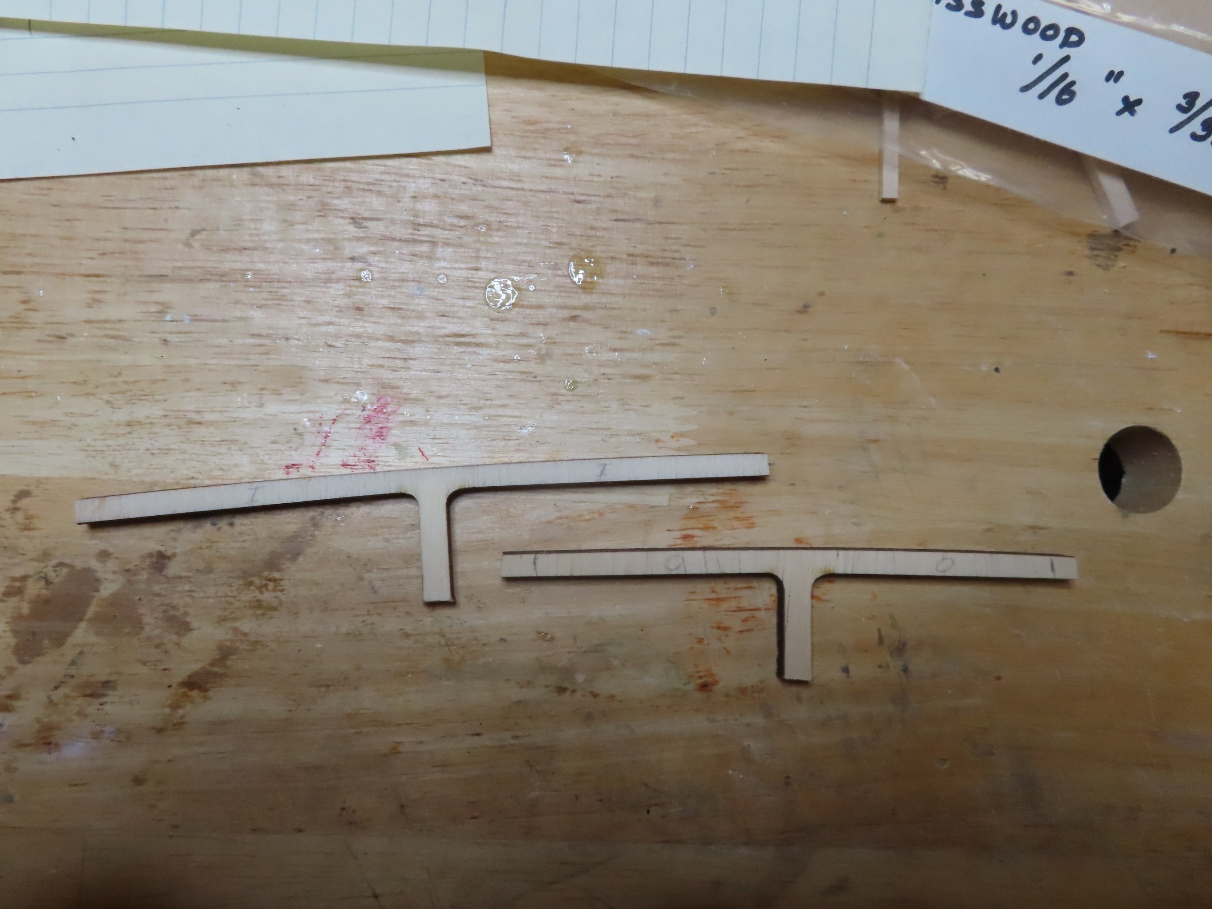
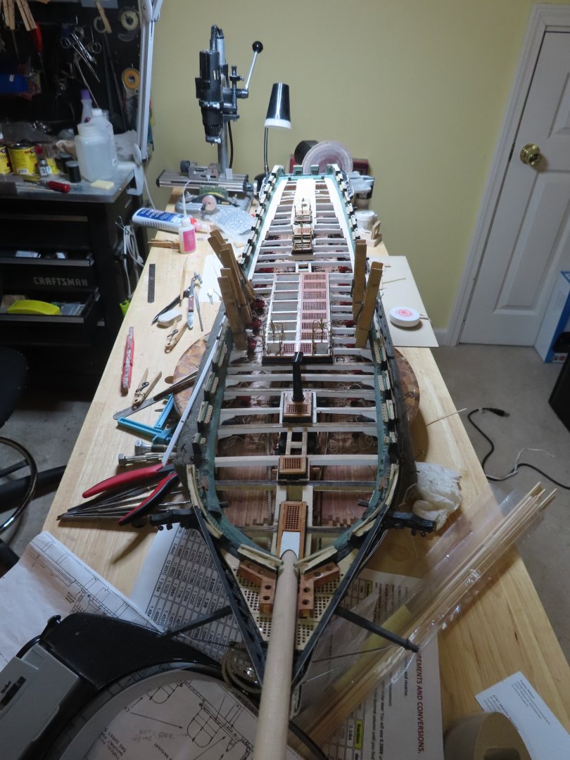
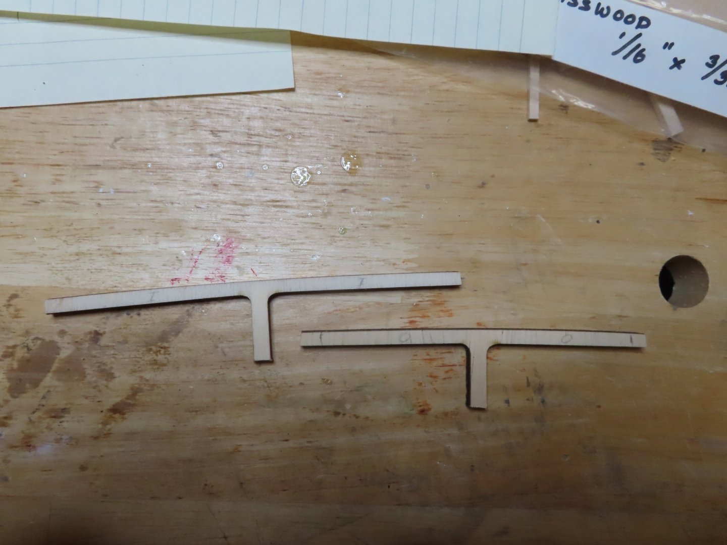
In order to install the captain’s skylight and its railing, requires that I start planking the aft section of the spar deck. It’s been a while since I last planked the gun deck, so I reviewed the practicum on deck planking. It reminded me that I had to stagger the planking joints about ¾” apart in the adjacent rows. And where the two planks butt up against each other requires that there be a support beam below the joint. It was then that I realized I had a big support gap above the dining room area. I originally left this area devoid of beams because it wouldn’t be seen as it was to be completely covered with planking. However, it turns out that I did need them to support the butt joints. I don’t throw anything away while building a model. I still had the last two remaining support beams I originally cut off the bulkheads way back when. I needed these because they had the deck camber I needed. To use them, the vertical support was cut off and the width adjusted to fit under the spar deck waterway. I just had enough room to maneuver them into position and glued them into place with WellBond.


-
I always feel trepidation when I do things outside of the instructions/guidelines because once done, some things can't be undone. You have to make doubly or trippily sure you got all the measurements right. So far it looks like you've done everything right. Jon
-
Your welcome Gregg. I am always happy when my successes and/or mistakes helps someone else. Jon
-
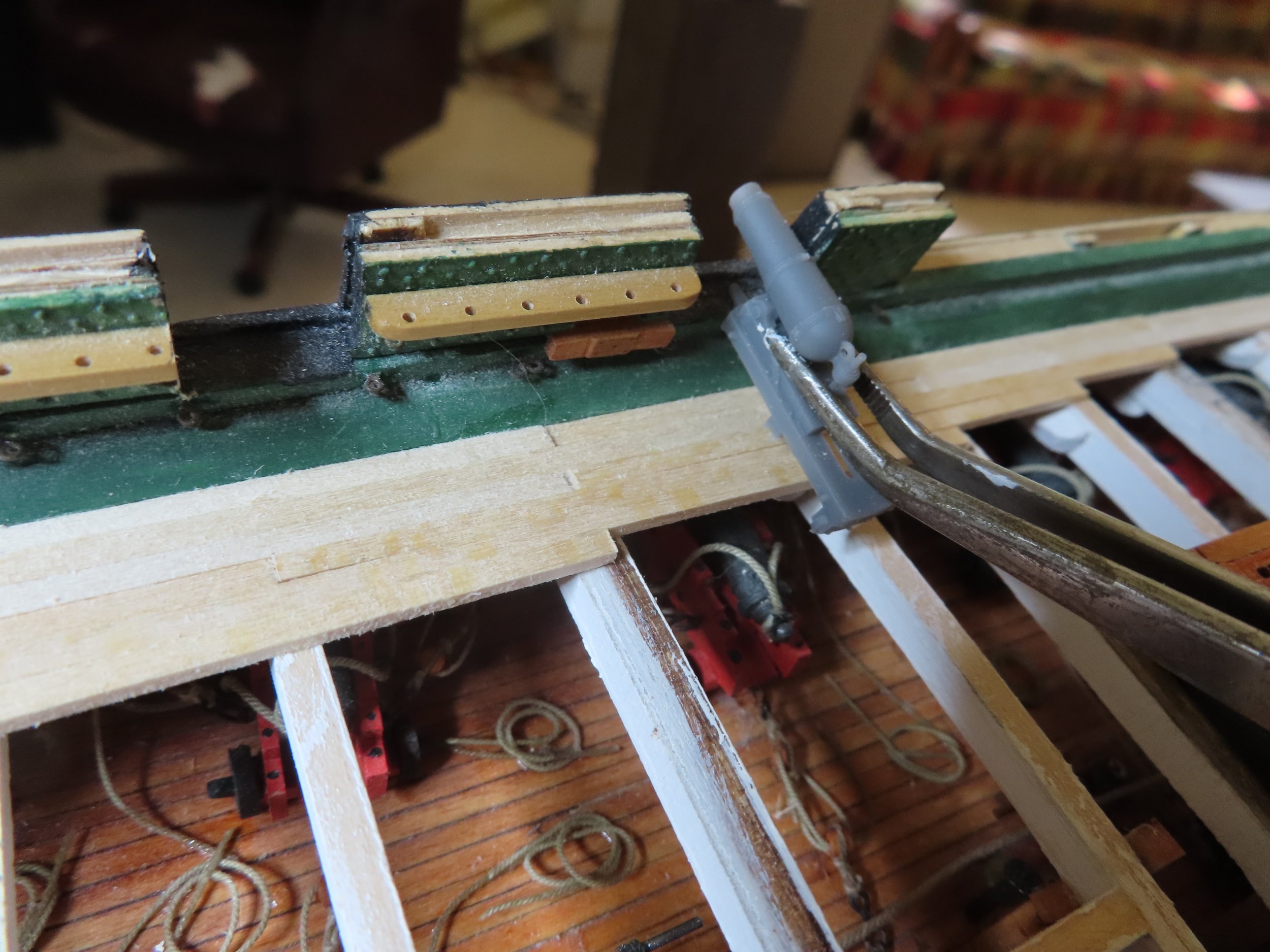
Those straps are relatively easy to make, but can be very tricky to install. They are so light, that the slightest, wrong breath or quiver of the hand can kick them out of alignment or knock them off altogether. And should they land on the floor, those little rascals run away and play hide & seek🤣. Well done! Jon
-
It's coming along nicely. Jon
-
Congrats. They look nice enough to frame and hang on the wall😁! Jon
-
I don't have a woodworking shop. I do have a Byrnes saw (an absolute must), Byrnes Thickness sander (hardly used), small wood lathe (hardly used), a disk sander, a cordless variable speed Dremel, corded Dremel like tool, a 50yr old Dremel scroll saw, and a 20 yr old Dremel drill stand. These I collected over the years. Of course I also collected a bunch of hand tools, some I use a lot and some weren't worth the money. But what is most important is lots of patience, desire, tenacity, problem solving, and a healthy dose of crazy. For me, the the journey is the hobby. Once the model is done, it's done and you either put it on display, sell it, or give it away. But it's like eating potato chips, you can't eat just one. This will be my last big model. I figure I've got another couple of years to completion and I'll be in my 80s, so I'm going to enjoy this ride while it lasts. Anything I may build after that will be small fun stuff. Jon
-
Welcome to Model Ship World! I've been following you on SOS, albeit in silence. You've accomplished quite a bit; a lot more than me in the same time period. My excuse is that I added furnished gun deck and I just work slow, so I wouldn't be surprised if you completed your model before me. Oh yeah, I've been working on my build 8 years now and have just started the spar deck. I look forward to you future posts. Jon