JSGerson
-
Posts
2,640 -
Joined
-
Last visited
Content Type
Profiles
Forums
Gallery
Events
Everything posted by JSGerson
-
 You might even get away with painted vertical lines!!?? Jon
 -
There is always the layer cake alternative, the method I used for my catheads. Although, I too would prefer just to drill them. Jon
-
I too plan on replacing the fife rails. The ones that come with the kit are fragile...very fragile. Look at them crossed eyes and they will break. Imagine inserting or tying off lines to the belay pins and the rails break after they been installed. Not a pretty sight. Using boxwood, NOT basswood, was the proper wood replacement choice. Don't forget to anchor the rail and bitt assemblies to the deck with pins. There will be some stress placed on them when the rigging is installed. Jon Jon
-
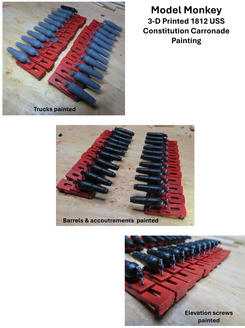
Painting was also a tedious endeavor because I was painting a complete model…22 times. Painting individual parts before assembling is a lot easier. These were complete guns with attached trucks. First, I painted the trucks Model Expo acrylic orange/red. Then I painted the gun barrels, mounts, and small accoutrements on the trucks, Model Expo acrylic black. Getting all the nooks and crannies covered with paint was not simple as I kept missing spots and had to keep going back to cover those surfaces while trying not to touch previous painted areas…but I did. When I fixed those, I reintroduced additional painting errors…etc. Finally, all I had left was the screw mechanism for adjusting the barrel elevation which I painted Testors enamel steel, which I already had.
-
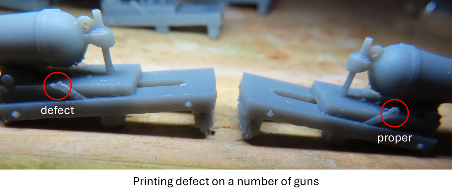
Spar Deck Carronades Now for the carronades. I wanted to fabricate the carronades like I did the gun deck, guns. However, as I have mentioned preciously, I purchased 3-D printed carronades because they matched quite closely the carronades depicted in Marquardt’s book. The amount of work it would have taken to separate the gun barrels and mounts from the trucks without damaging anything, just so I could make my own trucks resulting in no appreciable difference, did not seem worth the effort. So, I swallowed my pride and decided to the printed guns. Removing the spruce trees from 22 guns was slow, delicate, and tedious, and unfortunately revealed one persistent defect. Several guns had one or more deformed eye bolts, required for rigging the guns. I have some ideas for a repair in the near future. In the meanwhile, painting the guns is next.
-
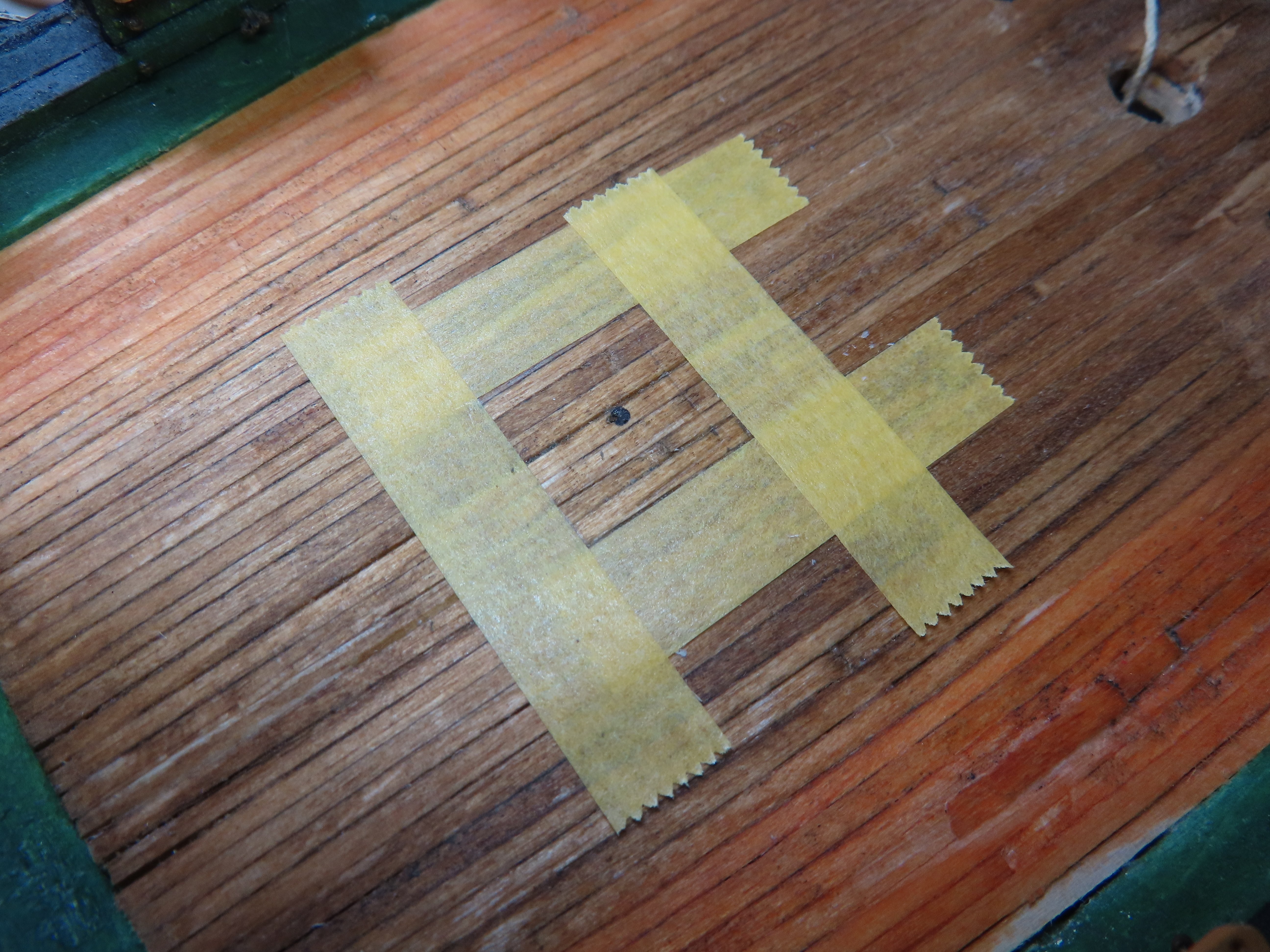
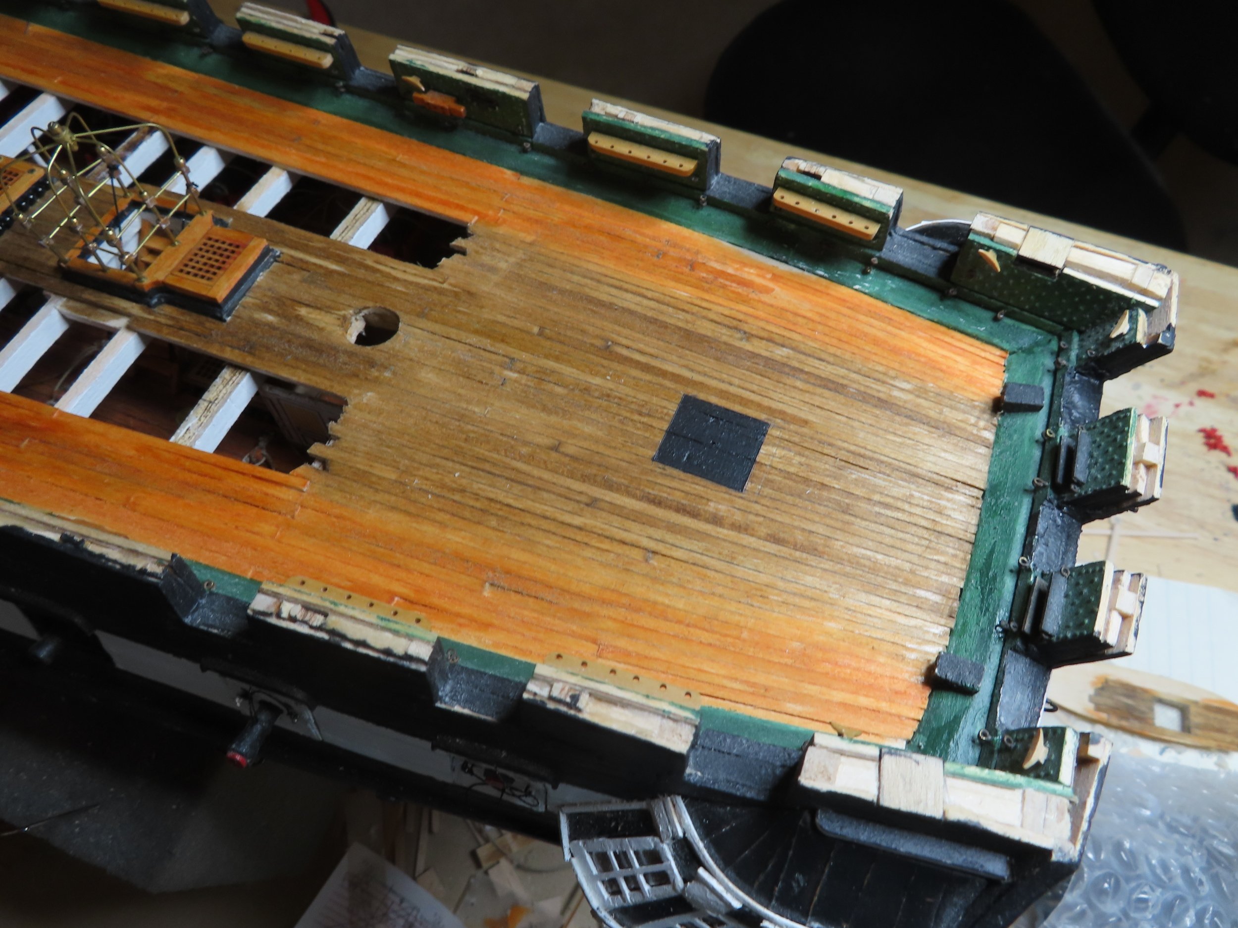
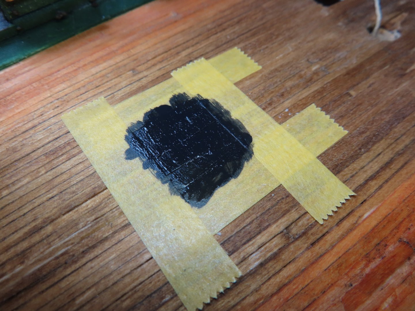
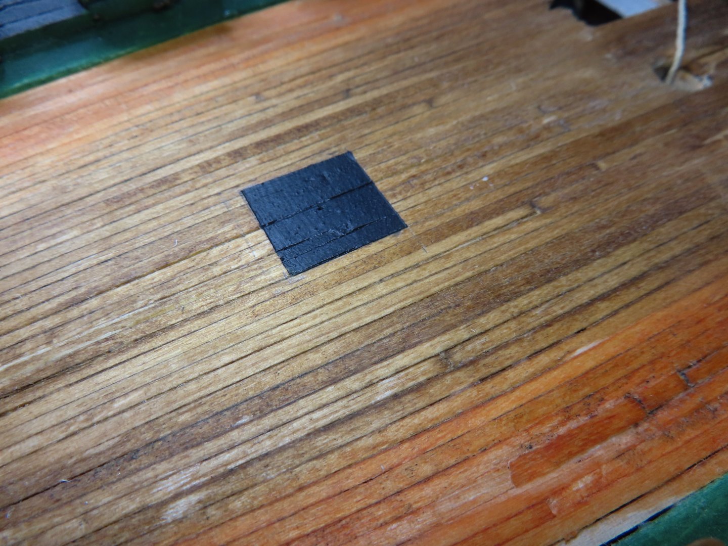
You may (or not) have noticed that the stove stack is missing in some of the most recent images. This is because due to working on the spar deck, my hand has been constantly bumping into it. So, I took it off for safe keeping. On that same note, I decided to delay installing anything to the spar until all the carronades have been completely installed. However, one partial exception was the black “plate” that the captain’s skylight will sit on. This was “installed” simply by painting a black square in the proper location. I’ll embed the stanchion bases into the deck when the skylight is installed.


-
USS Constitution by mtbediz - 1:76
JSGerson replied to mtbediz's topic in - Build logs for subjects built 1751 - 1800
Here are two sources of miniature rope I've used and recommend, I am sure there are others. Ropes of Scale: https://ropesofscale.com/ Syren Ship Model Company: https://syrenshipmodelcompany.com/ Jon -
USS Constitution by mtbediz - 1:76
JSGerson replied to mtbediz's topic in - Build logs for subjects built 1751 - 1800
Pushing thread (miniature rope) through small openings can be frustrating. What a lot of us do is dip the tip of the line into some thin CA glue so it wicks into the threads. Once the CA dries and the tip is rigid, I take an X-acto knife and cut a long sharp point in the stiff line. This makes it easier to get through the eyebolts, blocks, or whatever you are trying to get through. You are going to waste a lot of line cutting off excess material after you adjust the line for length. It's just the nature of the process. Remember, the process is a journey, not a race, so "stop and smell the roses" (not the glue 😁) as you move along. Jon -
Those "eyebrows" look great! And yes, there are a lot of "fun" to make for the gun deck, each one a miniature model unto themselves. The only downside is that a lot of those nice details are hard to appreciate while partially hidden under the spar deck due to limited viewing accessibility, at least on my model. I look forward to your future posts. Jon
-
You've got one beautiful model!! Jon
-
USS Constitution by mtbediz - 1:76
JSGerson replied to mtbediz's topic in - Build logs for subjects built 1751 - 1800
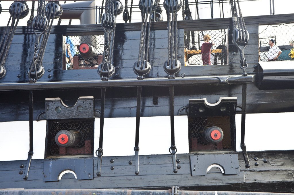
I suspect on the actual ship, these metal pieces were painted to protect the bare metal from corrosion. And looking at these pictures closely for the first time, because I haven't reach this stage yet, they are made of two pieces. We are making models, not miniature replicas so this probably won't matter. Just thought you might want to know. Jon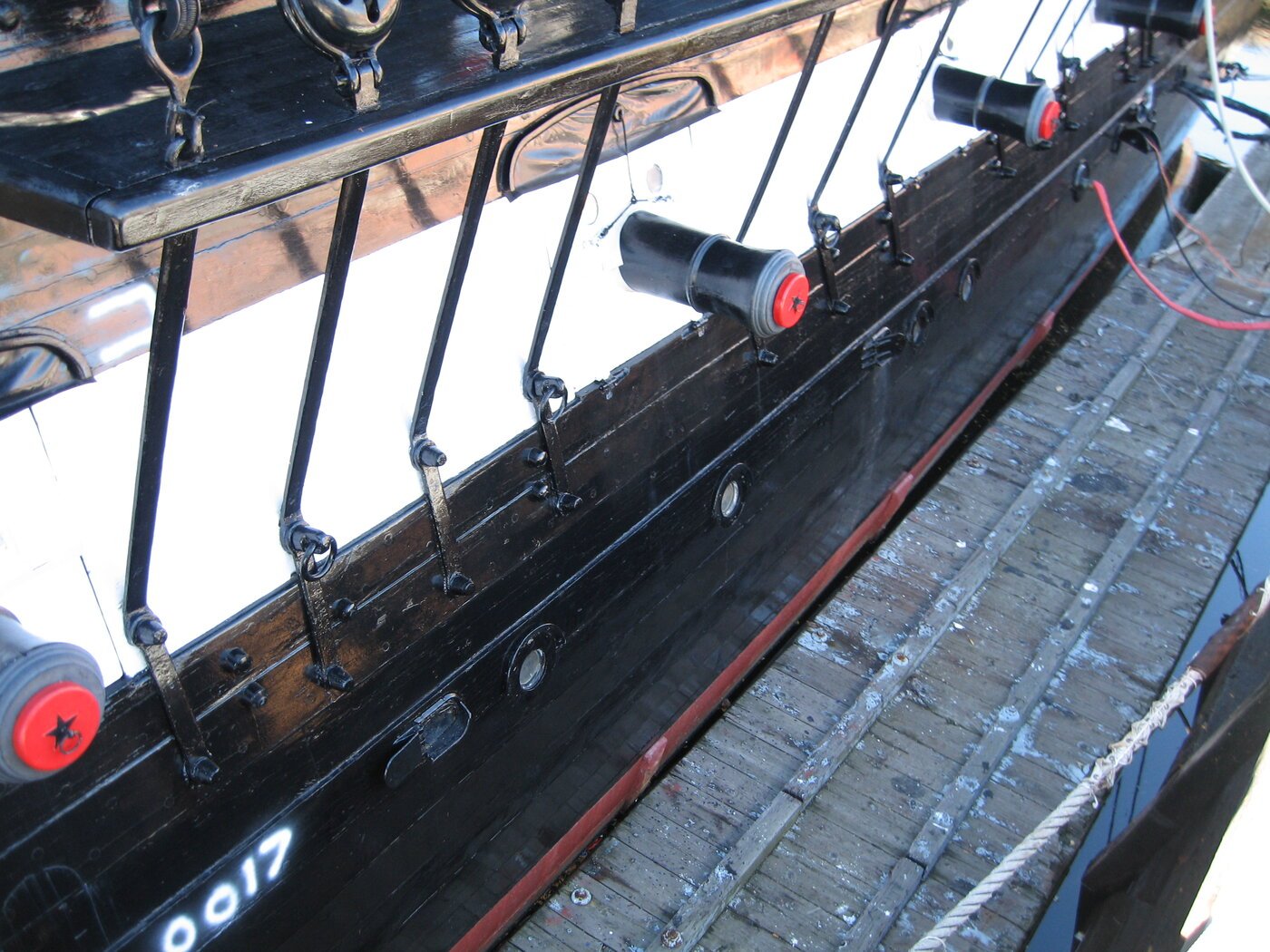
-
The Model Shipway USS Constitution is only my second wooden square rigged ship build. My first was the Mamoli Rattlesnake. I would not have even considered building the first, if it weren’t for Mr. Hunt’s practicum, flawed as it might be. By the time I was completing the Rattlesnake I realized that Mr. Hunt only provided enough detail to make a nice, but not a great model. He never completed either of his models, but he taught me a lot. As a result, I had no hesitation to not only attempt the USS Constitution, but to scratch build its gun deck as well. The best tool decision I made was to buy the Byrnes table saw. It is precise enough that I can cut wood strips as fine as 1/128” thick or wood pieces up to 1” thick. I have a small lathe which I have hardly used so far, a couple of Dremel rotary tools, a drill stand that holds a Dremel drill, a 50yr old Dremel scroll saw (a must have tool), a small disk sander, and a Brynes thickness sander (used occasionally). I’ve accumulated a bunch of hand tools and jigs, some imperative and others useless. Your best source of information is this site (or site like it) and YouTube for the “How-To” info. I believe Model Ship World is one of the largest, if not THE largest wooden ship model site on the internet. Jon
-
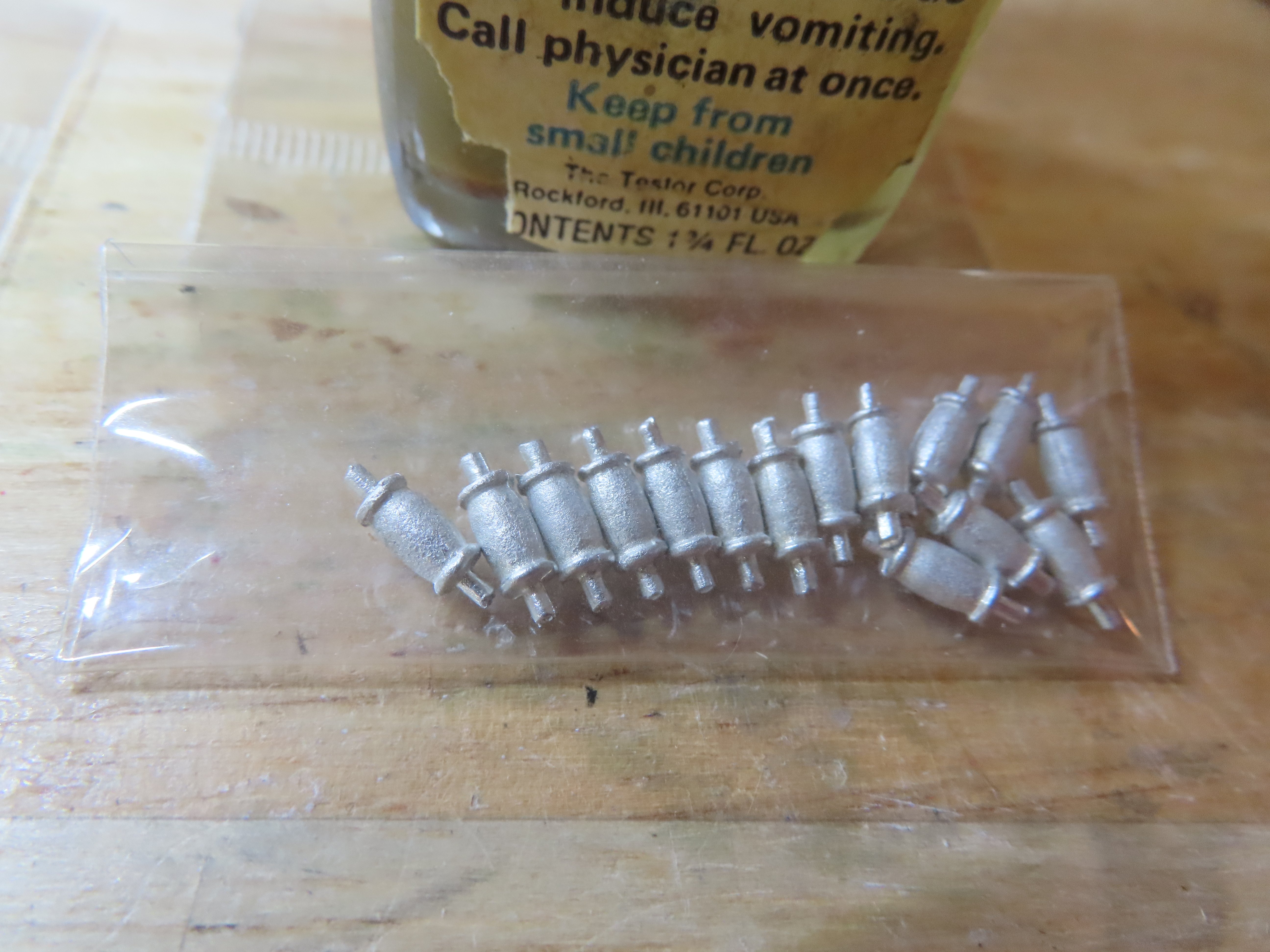
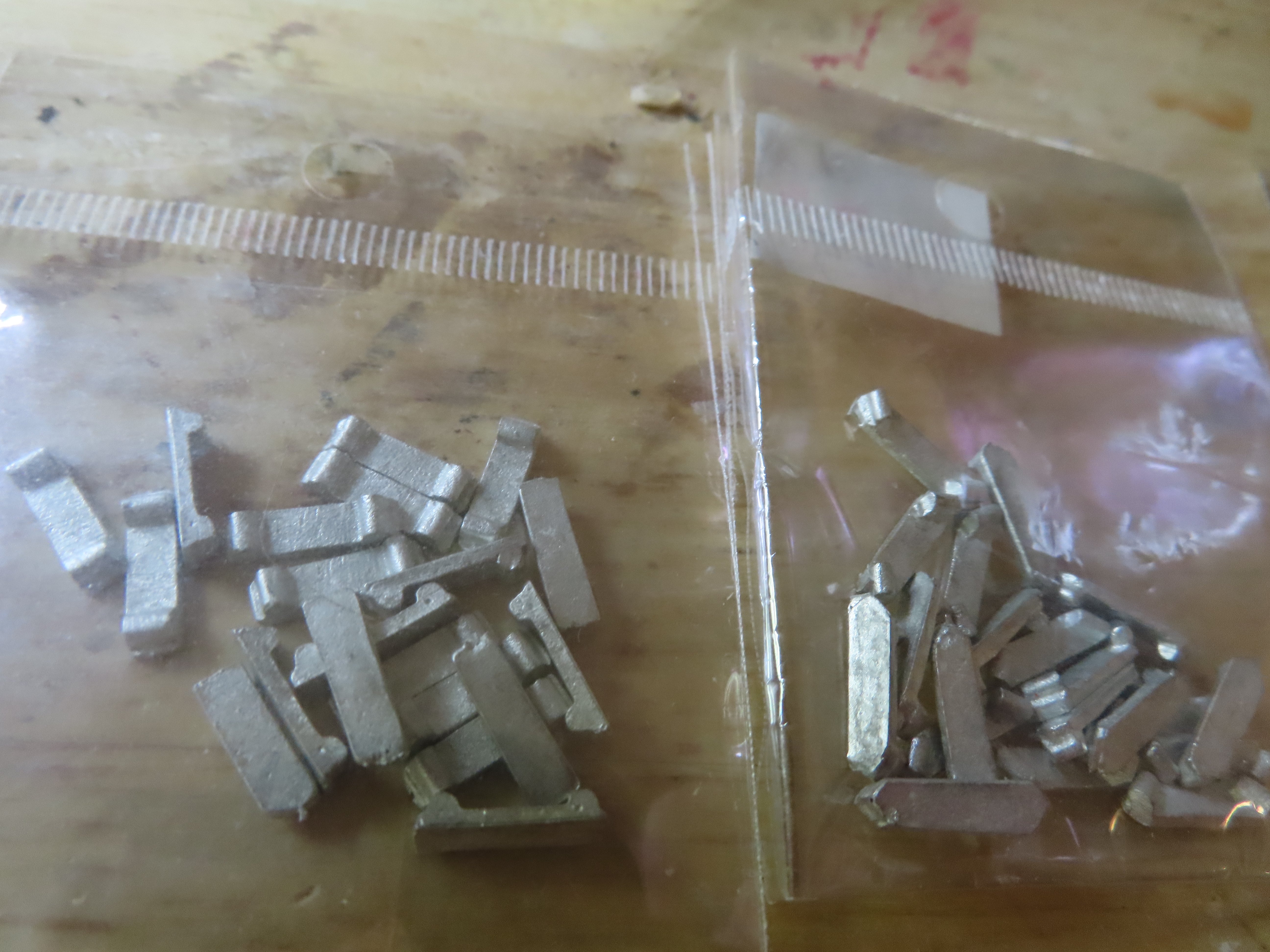
Before I sent out the "mystery"post I did go looking for the parts list. It was not in the kit box. It's probably buried in the piles of paper I've generated of notes, instructions, conversion charts, etc. I've accumulated over the years. I did have the foresight to scan the paper work I received with the kit. I finally found it in a file on the computer. I had a hunch, and you guys matched it about the carronade trucks. They were the front and back trucks, in separate bags. The rolling pins turned out to be fife rail stanchions "round portion only." Thanks for the quick reply. Jon
-
I've got a mystery, which I hope some of you MS Constitution kit builders have already solved. I've got three bags of Britannia Metal accessories. I have no idea what they are or where or when they are supposed to be used (or should have been used). The image of the left shows a bag of something like rolling pins and the image on the right show two bags of something, but of slightly different sizes. Can someone please identify them...please🤷♂️


-
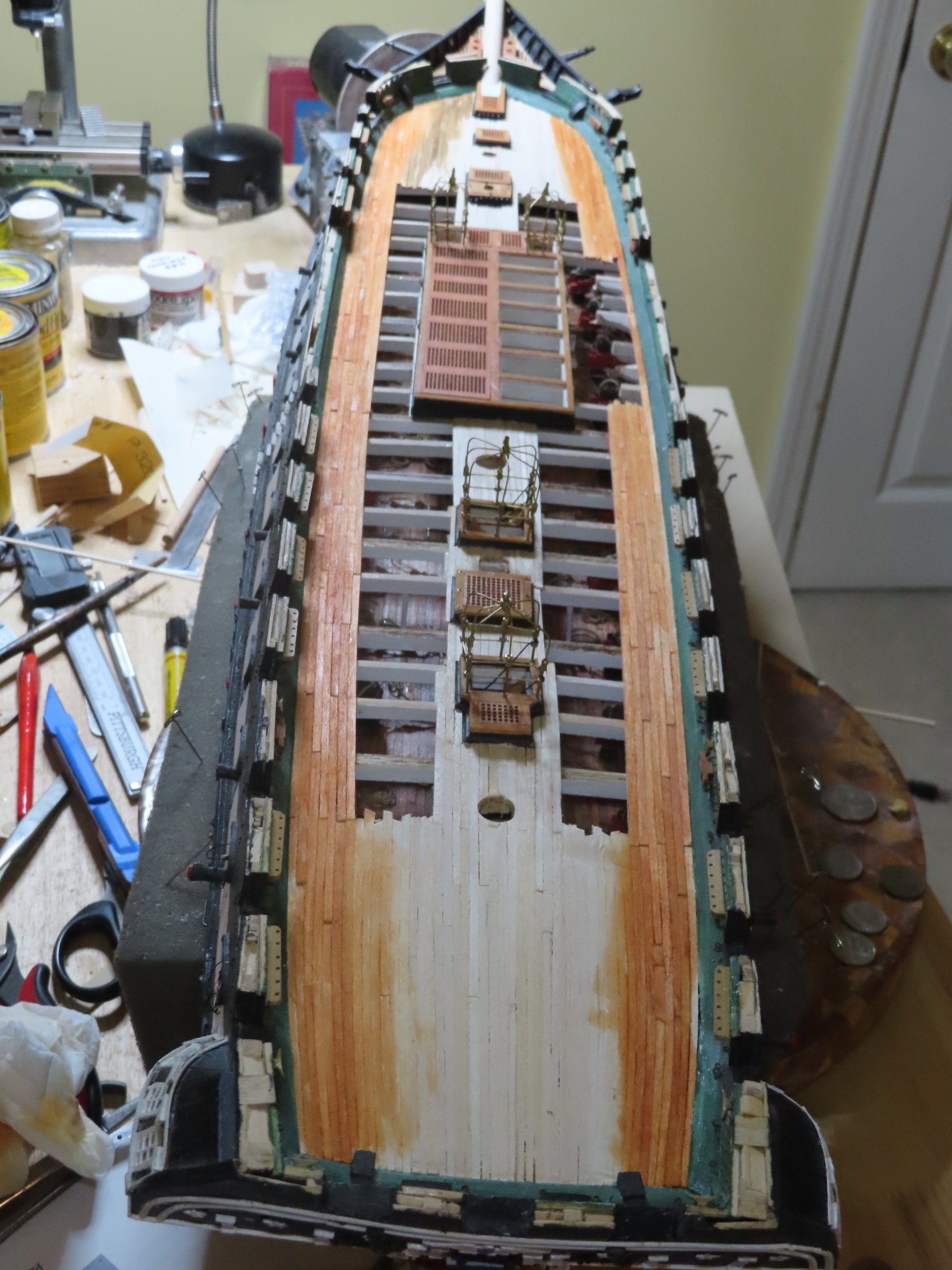
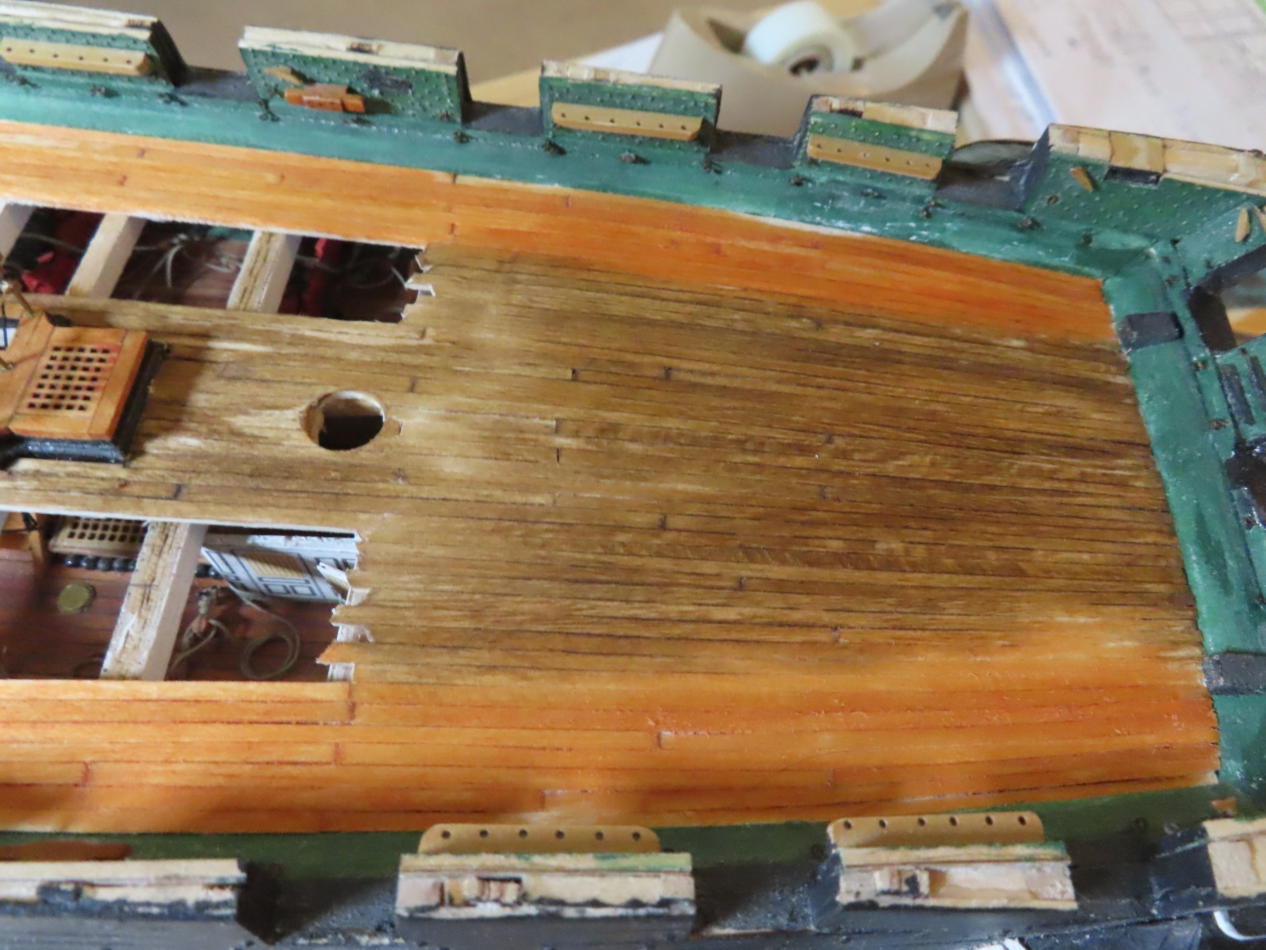
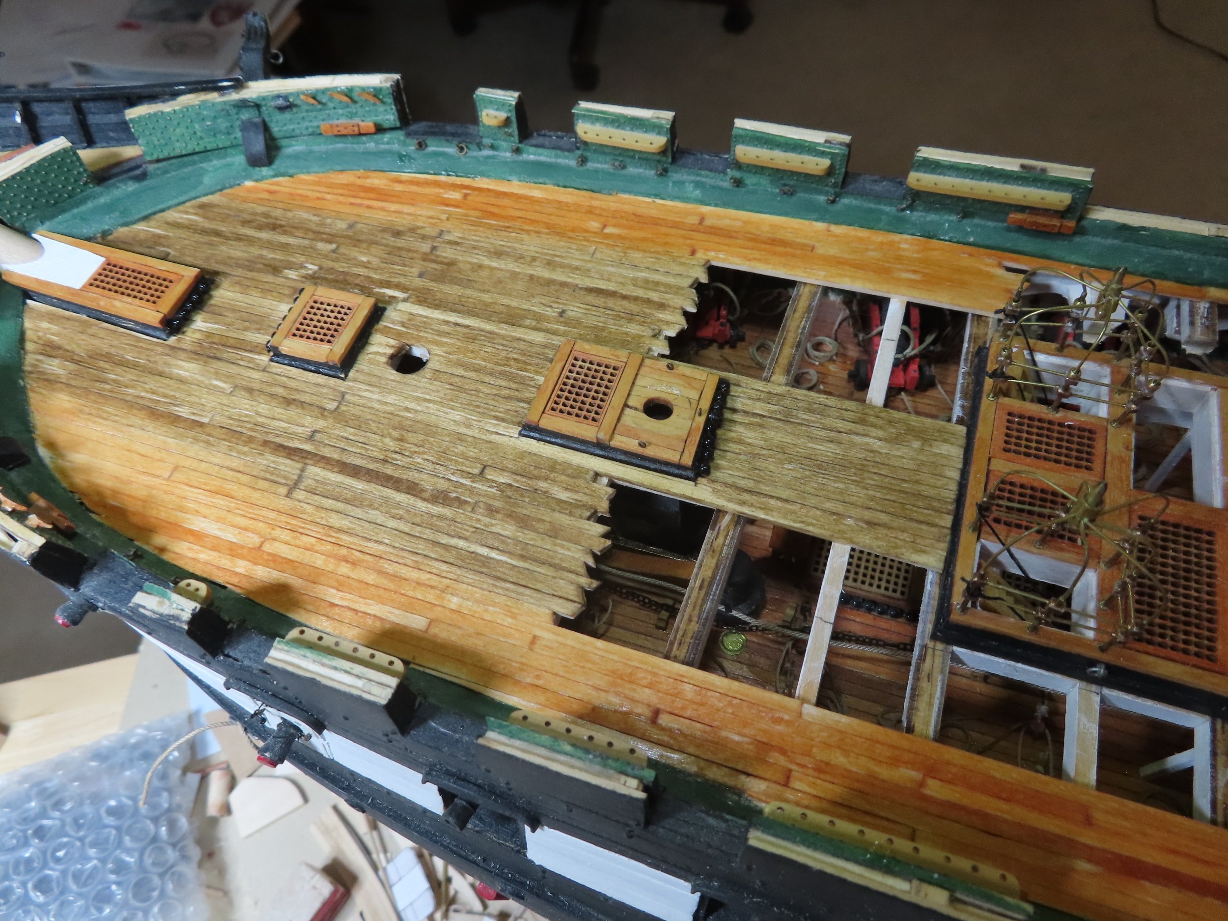
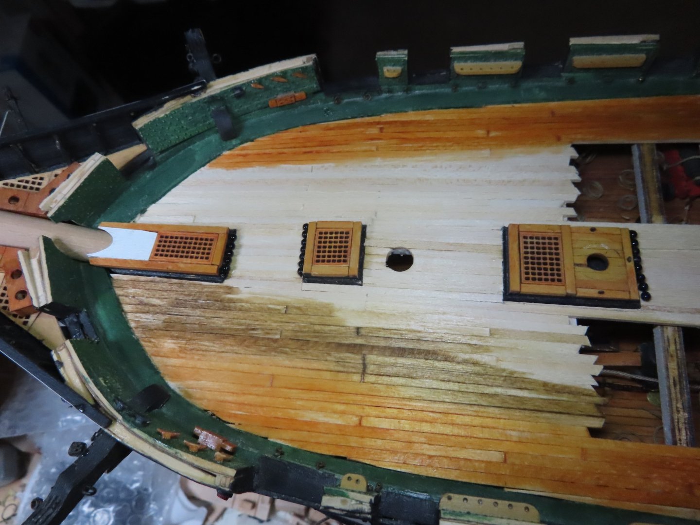
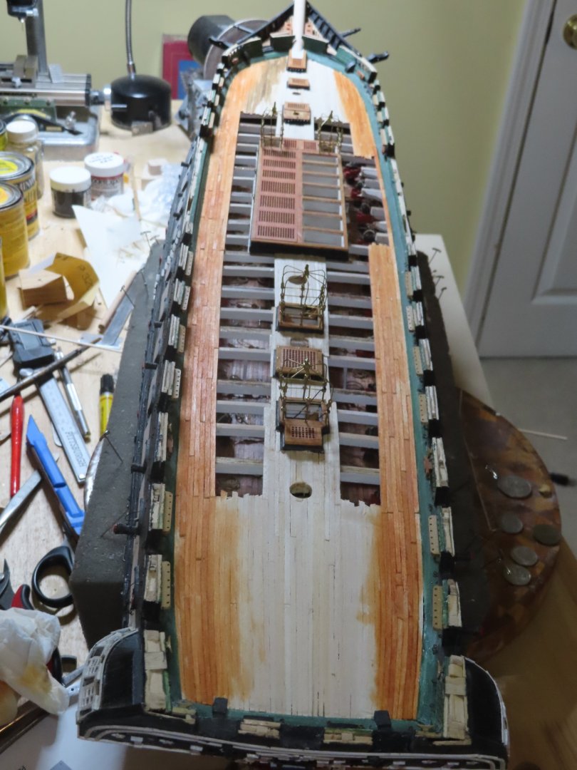
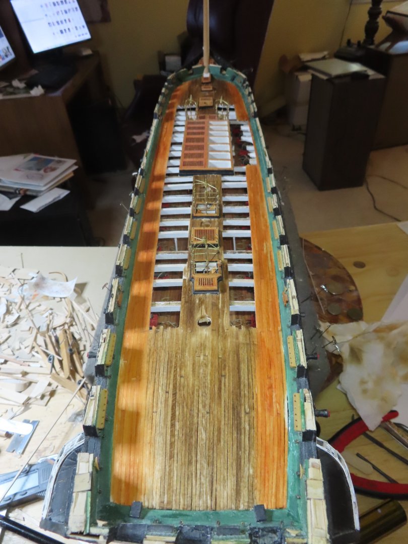
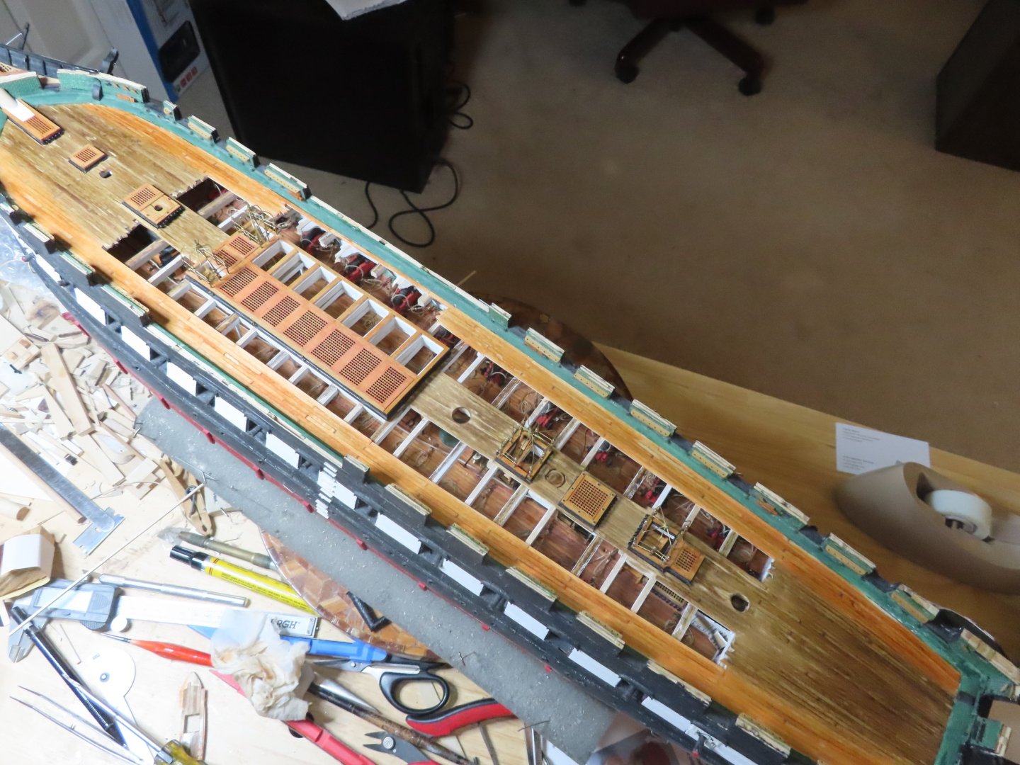
Now there are numerous items that need to be installed on the spar deck including the captain’s skylight. However, before any of that can be done, the spar deck must be stained first. This gave me some trepidation. As mentioned earlier, unlike the gun deck, the spar deck is open to the elements and weathers differently depending on the foot traffic around all the items on the deck, I must get the stain done right and done right the first time. Area According to the practicum, Mr. Hunt had an elaborate process to accomplish this. Unfortunately, some of the products he used are no longer available, specifically Floquil Grimy Black and Floquil Roof Brown or any Floquil product for that matter. He would have you sand, apply paint, wipe off the paint, and scrape. I really didn’t like the idea of using paint in lieu of stains and physically scraping the wood. Other builders used different methods and color stains to get their weathered look, resulting in effects different from each other. The one thing I noticed was that all the spar decks were stained monotone, that is, no one area on the spar deck looked different than another. Yet, if you look at the images I posted earlier, there are color shifts. My model does not have a fully planked deck, so a lot of the dark areas shown in the photos will not exist. The area where the carronades are located, appear to have a more orange tint, while the foot traffic aeras along the center, bow and stern (on my model) are more brownish-black. This is what I will attempt to emulate. I did some tests with the stains I had available on scrap pieces of wood. I tried straight staining and various over lapping combinations. Based on those results I bought some more stains and experimented again. I think I came up with a simple scheme to get the desired results. I held my breath and took the plunge. The first coat consisted of two stains: Along the bulwarks where the carronades are, I used Minwax Gunstock 231. This has an orange tone. In the center area I used Minwax Early American 230 which is brownish tone. At the border where the two colors met, they overlapped each other slightly. Once the stains dried, the deck was lightly sanded. This time I streaked some dark tones with Varathane Espresso . This somewhat emulated Mr. Hunt’s colors of black and brown. Like it or not, it’s done, but I think it will work.


-
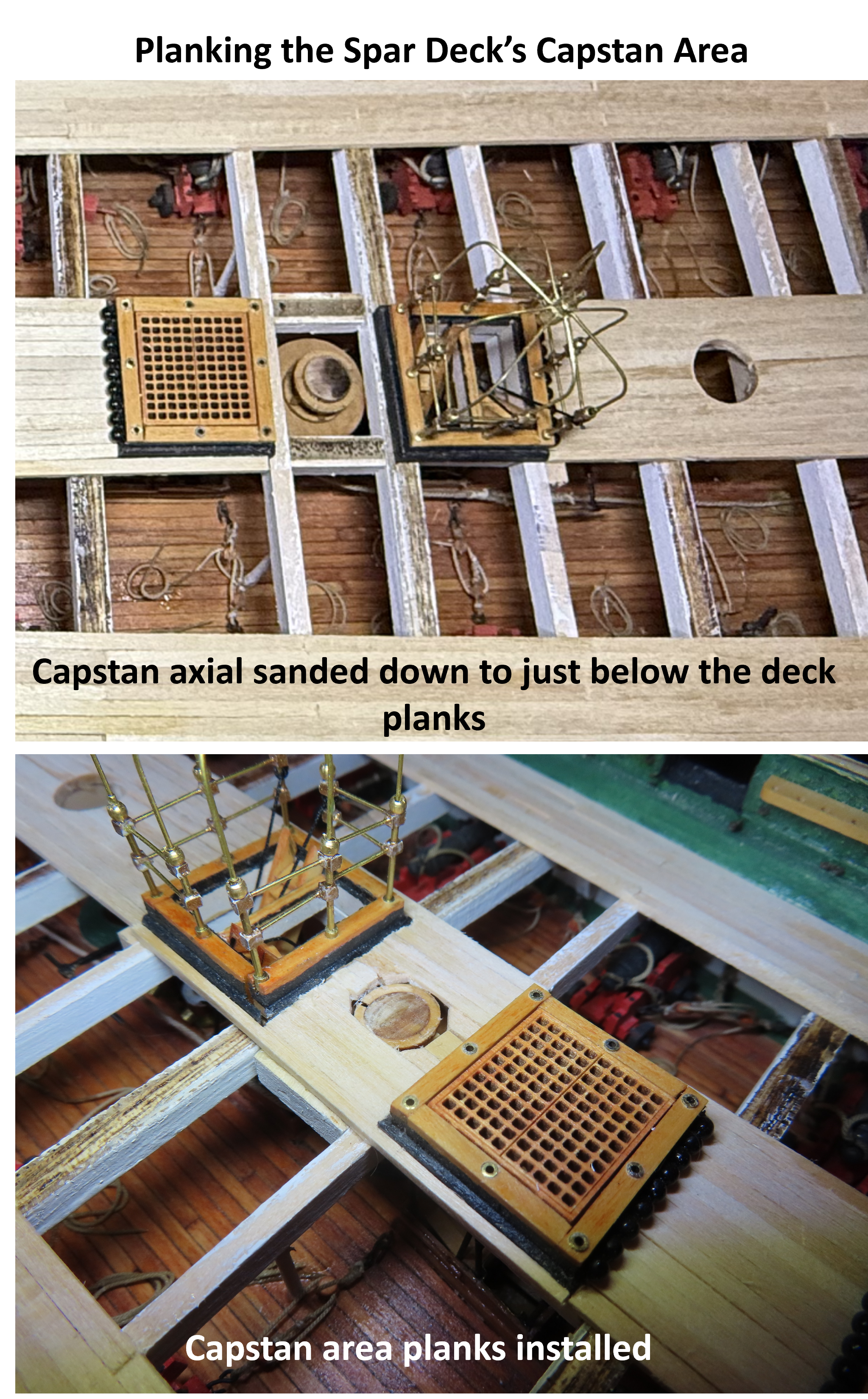
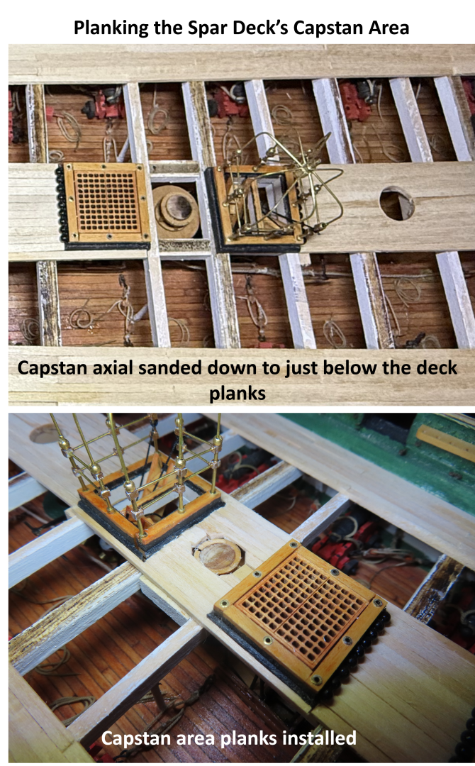
As I examine the capstan location, I realize that I made the gun deck capstan protrude about a 1/16” above the spar deck. At the time, I was thinking that I would extend the axial of the capstan into the spar deck capstan. As it turned out, there was no reason to extend the axial. First, attempting to get a perfect alignment would be tedious and second, it wouldn’t be seen. I sanded the protruding axial so that its top was just below the surface of the planking. Now I simply planked around the spindle. The area left open will be covered by the spar deck capstan. In the end, it won’t be obvious what method was used to install the spar deck capstan as it will all be hidden.
-
I've made a note! 👍 Jon
-
I know exactly how you feel. I've fabricated a large amount of stuff for my gun deck only to obscure most of it with a partial planked spar deck. We know the stuff is there, and that's what counts. If observers are truly interested in the model, they will look more closely and longer to be rewarded with more detail. The more they look, the more they will see. It engages them with the model and the builder. You've done beautiful work. Jon
-
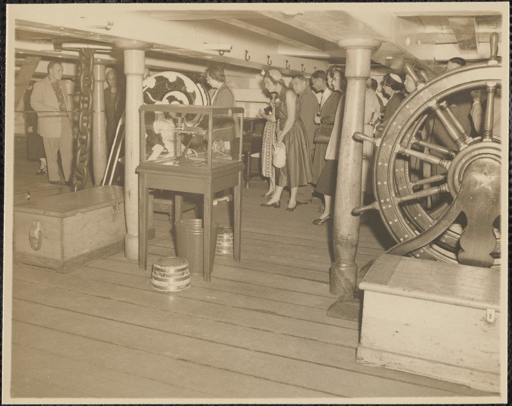
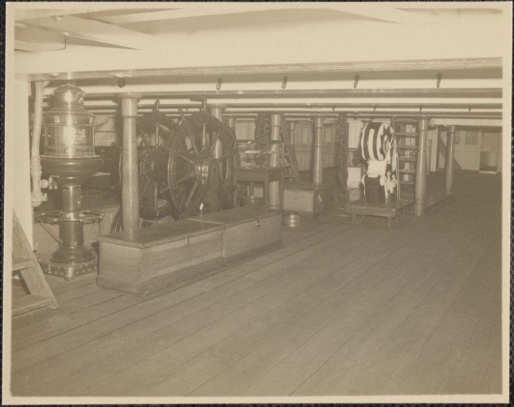
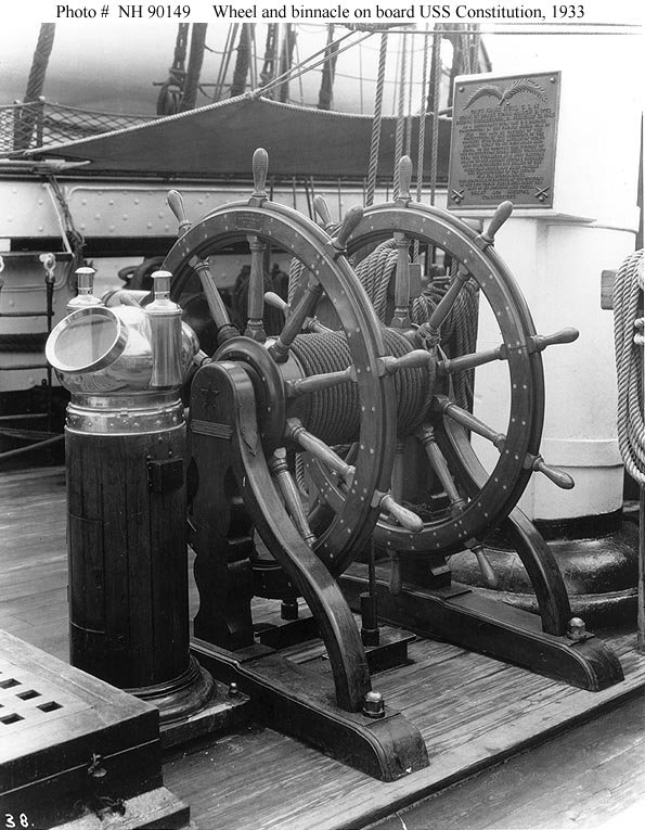
Here are a couple of more photos of the ship's wheel taken between 1940 - 1950. It looks like the wheel in the 1933 picture was removed and shown as a museum piece on the gun deck, Sorry, these images are not the greatest. Jon
-
I believe the modern binnacle was there for the practical reason the ship was on the ocean on tour under full sail part of the time and others being towed. She went through the Panama Canal all the way up the coast to San Francisco and back to Boston . Jon
-
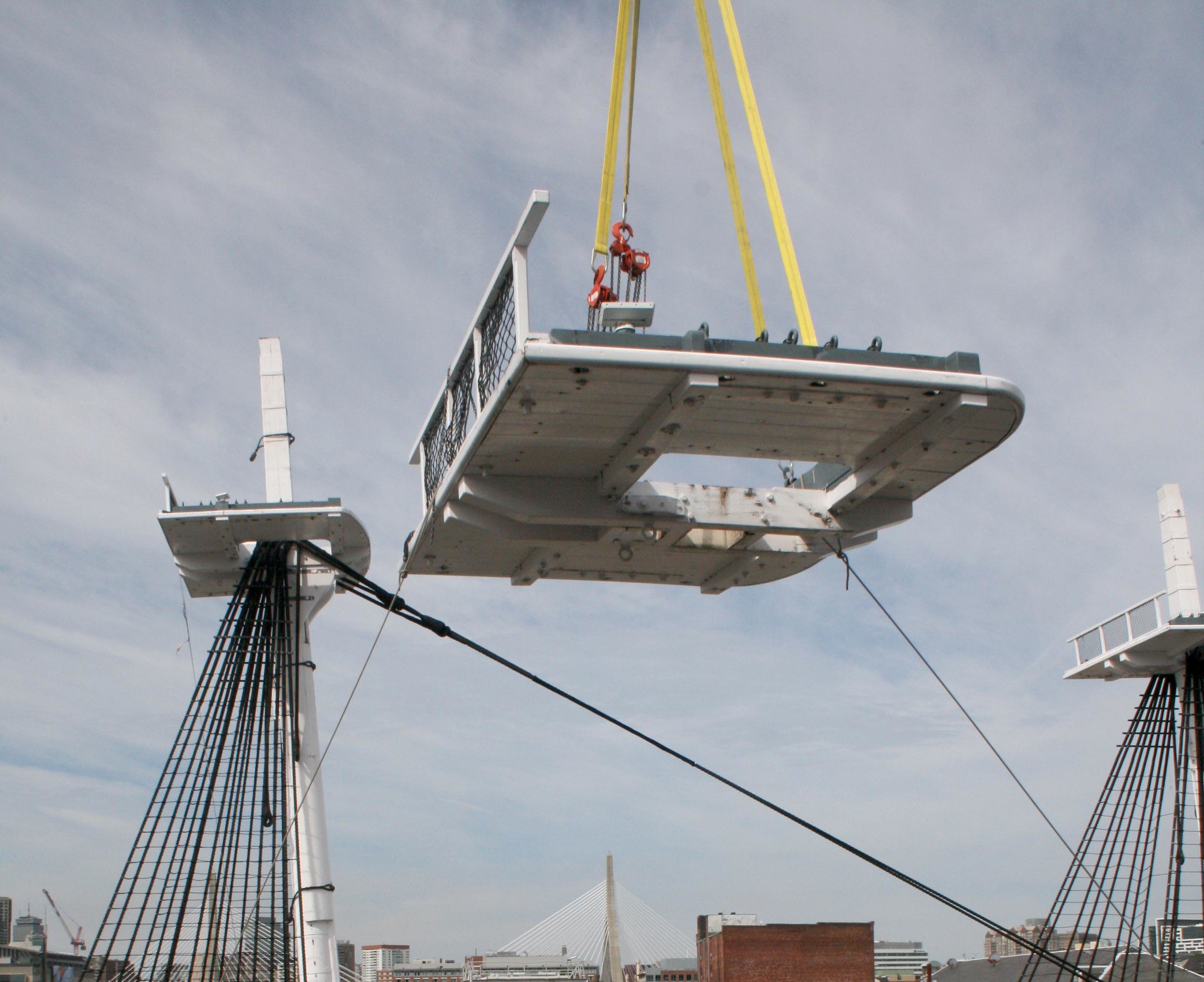
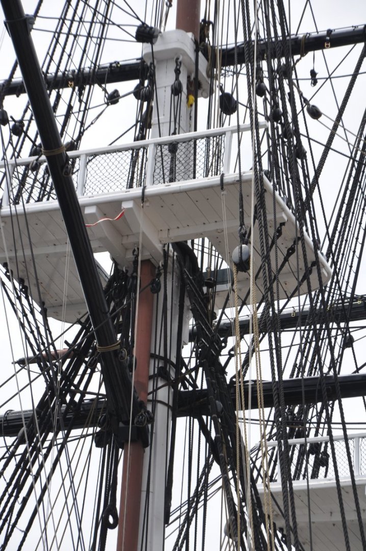
Thanks for the clarification. I went through my collection of images and found one, just one photo of the platform. It was taken during the 1931-34 National Cruise in 1933. Since the MS kit is largely based on the 1927 restoration, I'm not surprised it's part of the kit's plans. Therefore, I won't be adding it to my model either. Jon
-
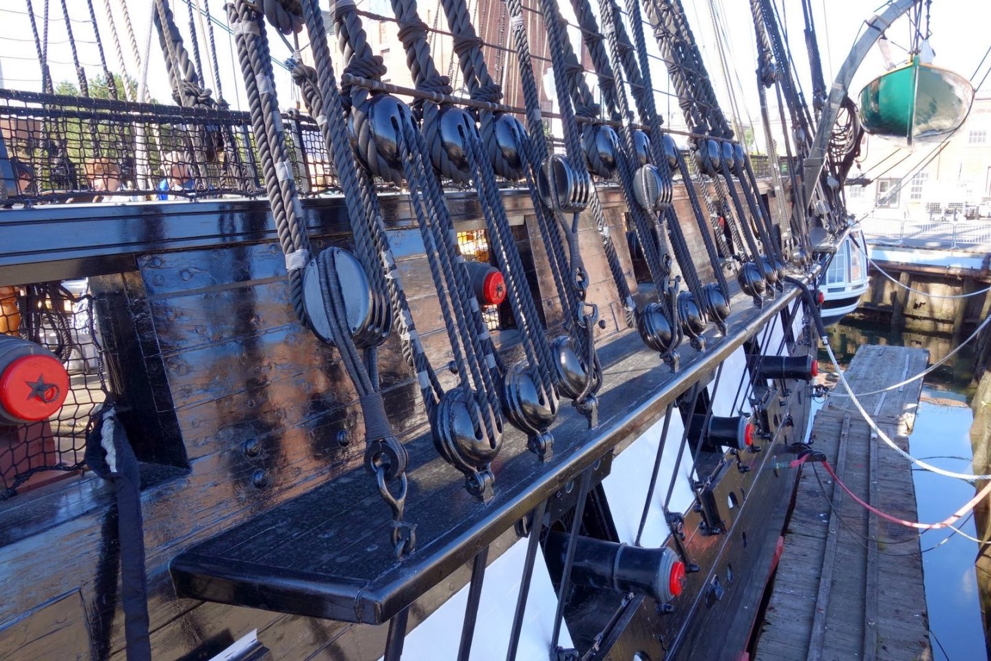
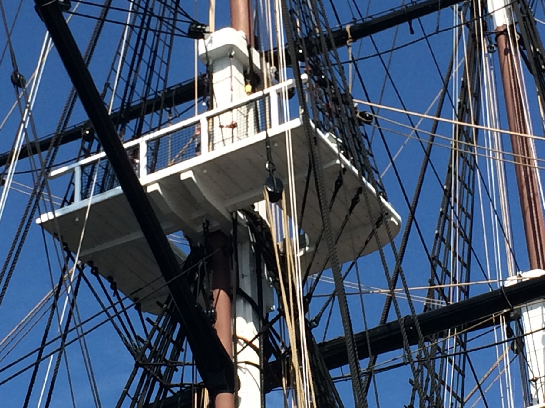
About the mizzen platform, I assume you mean the fighting top on the mizzen mast. If so, here are a few images of the platform where you can count the number of planks. I hope this helps. Jon


-
I hope mine look as good when I make the capstan. Based on yours and the the photo of the actual capstan, I might make the whelps a bit narrower with a lighter stain. However, I don't know if I can come close to your beautiful brass work with the tools I have. Nice work! Jon
-
USS Constitution by mtbediz - 1:76
JSGerson replied to mtbediz's topic in - Build logs for subjects built 1751 - 1800
Peter, didn't your MS kit come supplied with the grommets? Mine did. If yours didn't, you should be able to get a free replacement from Model Expo. Jon -
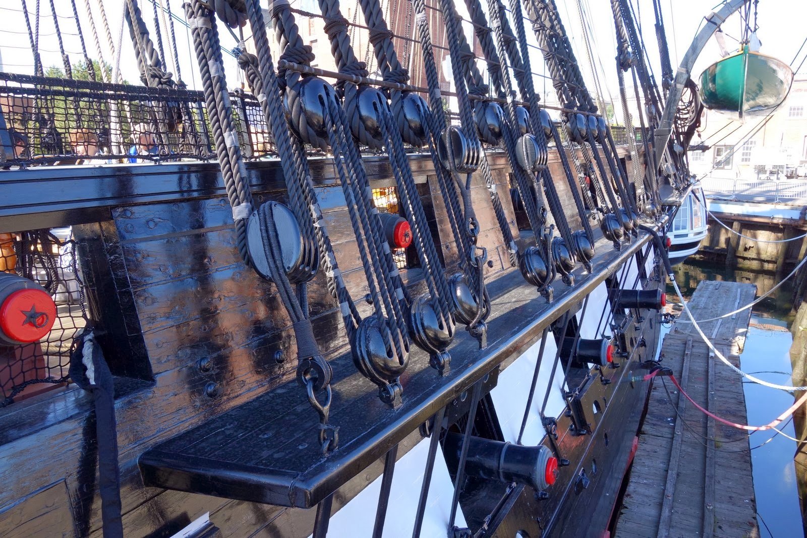
Yes, a very impressive service record. I never got any further than 3rd year Army ROTC while in college, when I was released from the program for medical reasons in 1969. But that's another story. Up to now, I have not looked too deeply into the deadeyes yet as I have not gotten that far in my build. (In case you haven't noticed, I'm very slow). So, I took a look at the real ship's hardware and discovered that for the lower deadeyes, the wire is not twisted, but doubled. It's a loop that goes around the deadeye and is bolted to the chainplate from both sides of the loop. At your 1:96 scale, a single larger gauge wire, twisted just at the meeting point at the bottom of the deadeye might be easier to do and would look more real than the twisted wire going around the deadeye. Jon