JSGerson
-
Posts
2,621 -
Joined
-
Last visited
Content Type
Profiles
Forums
Gallery
Events
Everything posted by JSGerson
-

USS Constitution by mtbediz - 1:76
JSGerson replied to mtbediz's topic in - Build logs for subjects built 1751 - 1800
Peter, I found the images of this model by Mark Antczak on Shipmodel.com, a company that sells boat models. Unfortunately, this model is not displayed any more at this site. However here is a limited blurb about this model from this Shipmodel.com at the time I down loaded the images: I will post the seven addition photos of this model that I have on your blog so as not to intrude too much on Mustafa's beautiful instructive blog. -
Rant on. 😫!!!
-
When in doubt with fillers between bulkheads, do more than less. It can't hurt to have extra filler. Jon
-
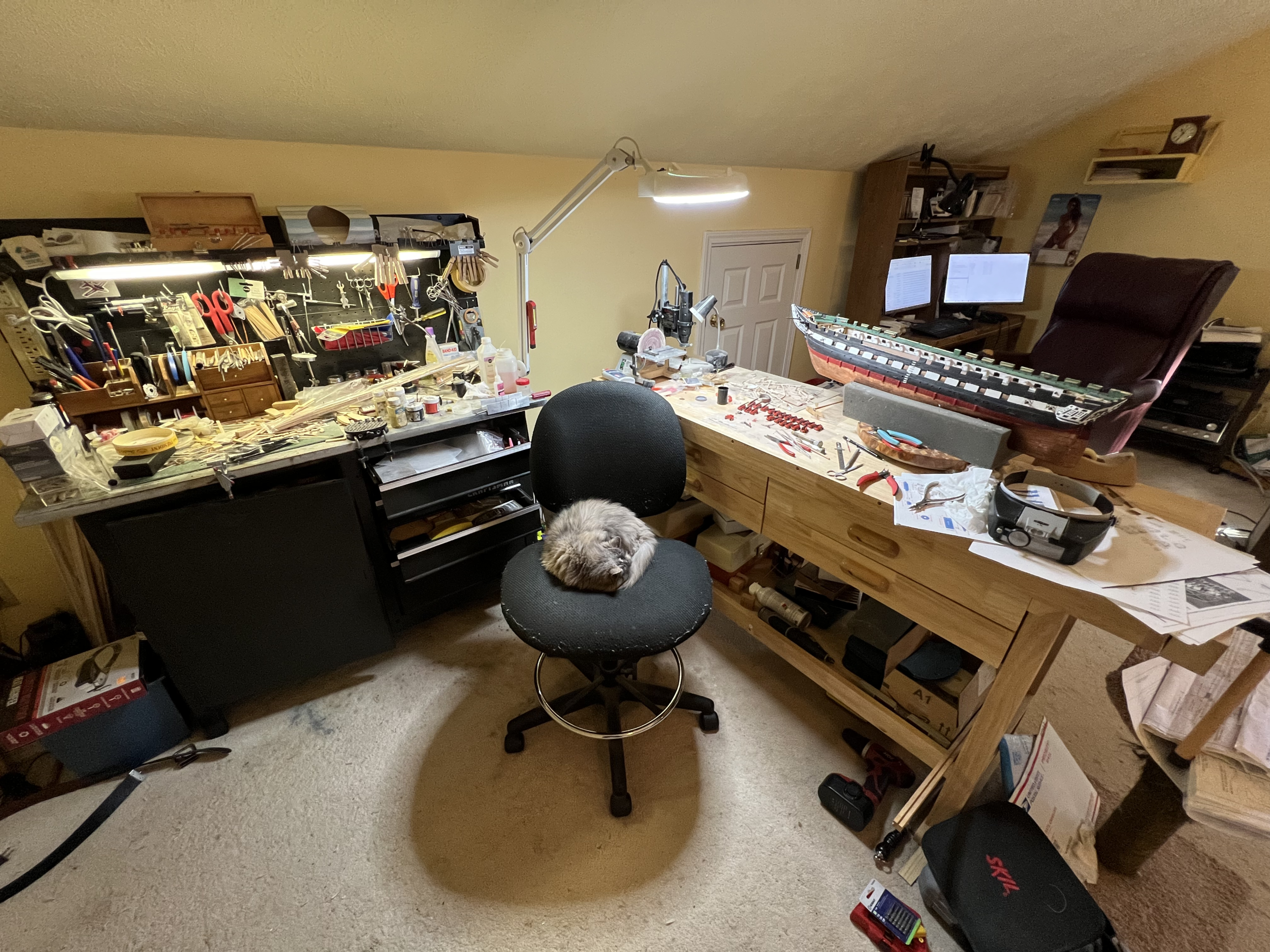
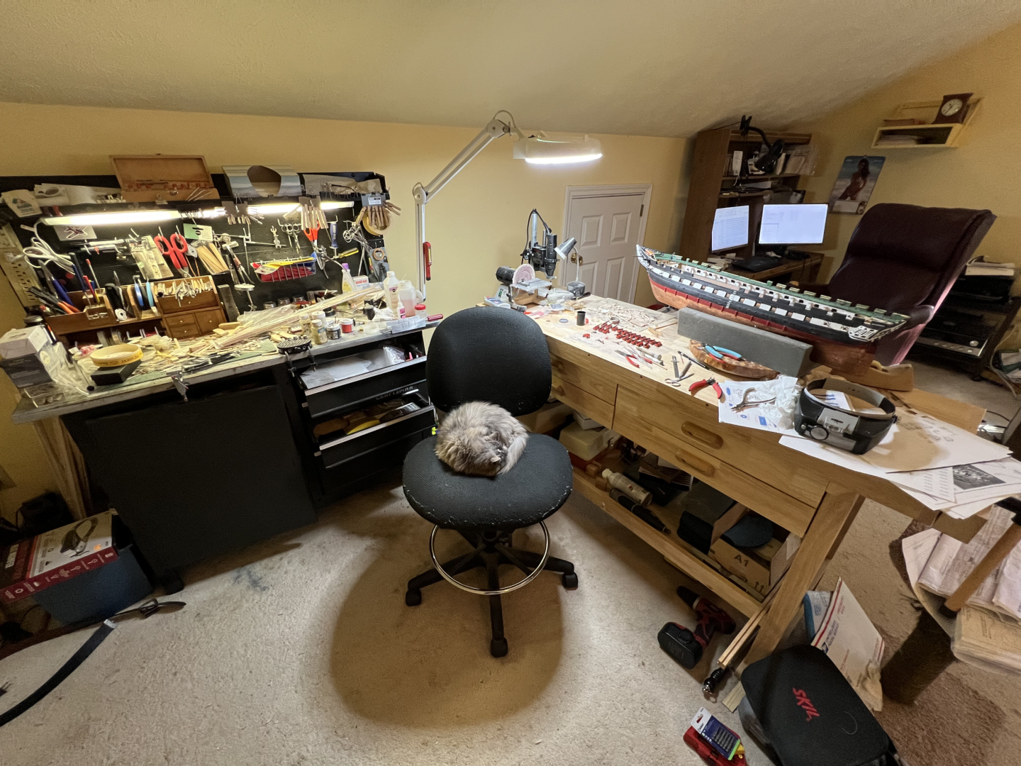
Here is my work area. It's the "bonus room" above my garage. What is seen in the photo is about 1/3 of the room. My major power tools are my Byrnes saw, Byrnes thickness sander, 50 yr year old Dremel scroll saw (very noisy and vibrates), and a small wood lather which are in the garage. You may also notices my astute "assistant" sleeping on my chair who periodically allows me to sit there and work.
-
USS Constitution by mtbediz - 1:76
JSGerson replied to mtbediz's topic in - Build logs for subjects built 1751 - 1800
Those pumps were not easy. I had a lot of false starts making those. Jon -
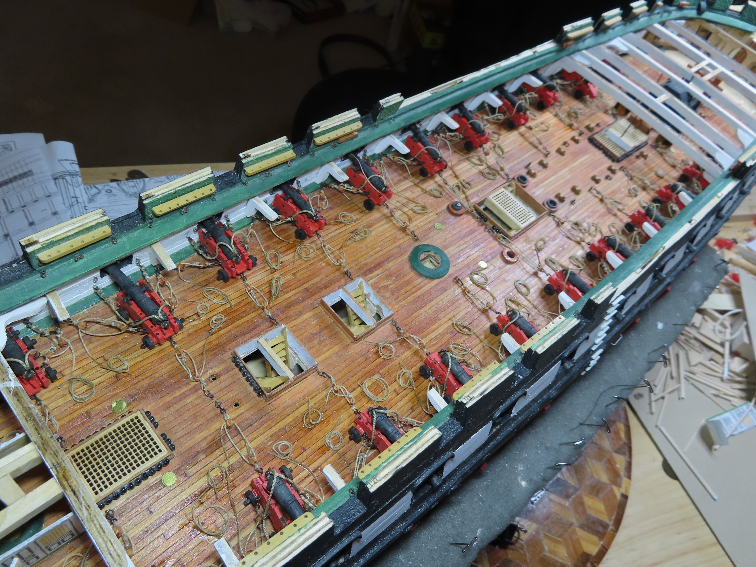
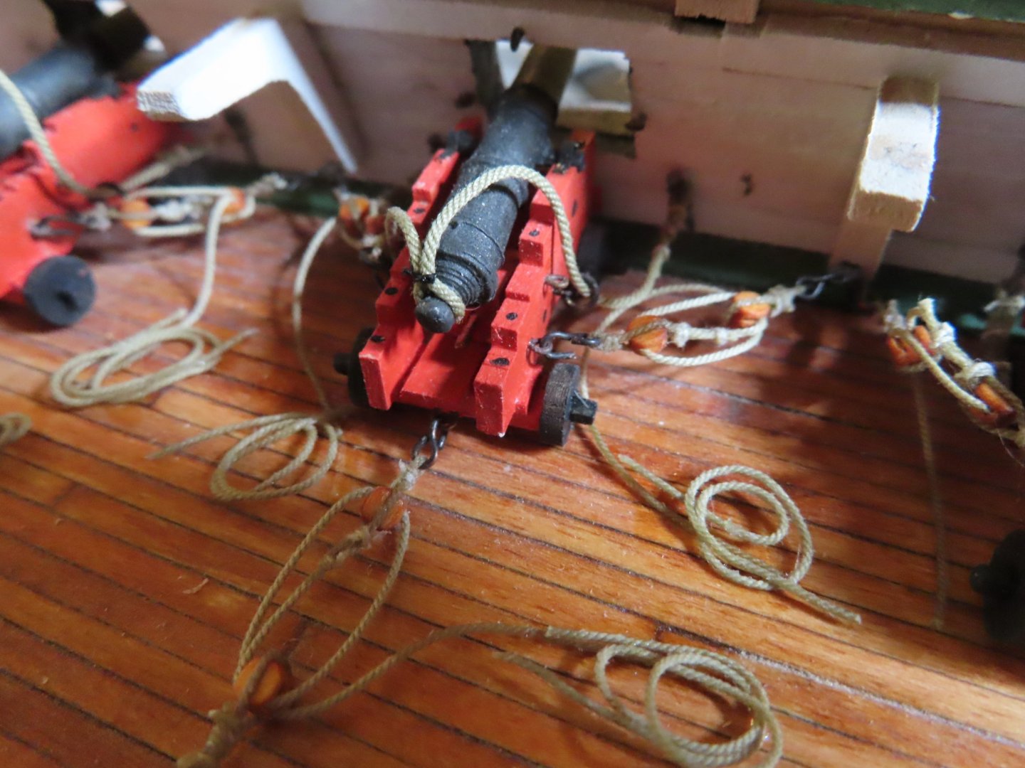
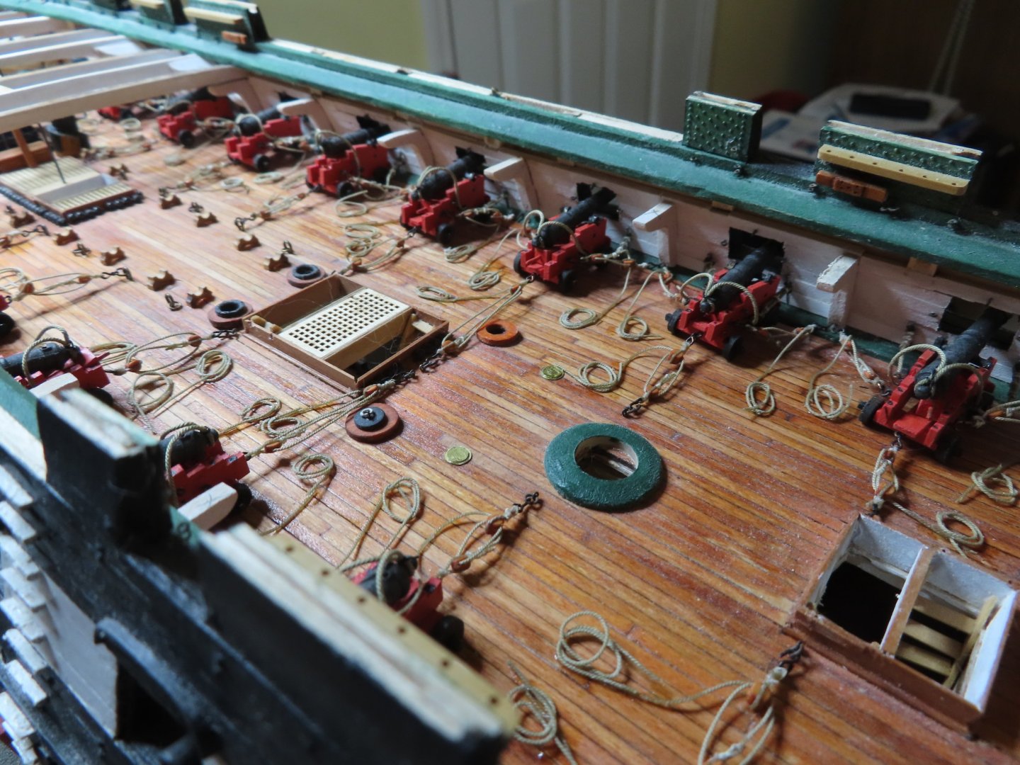
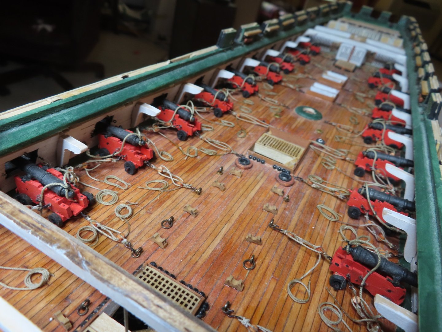
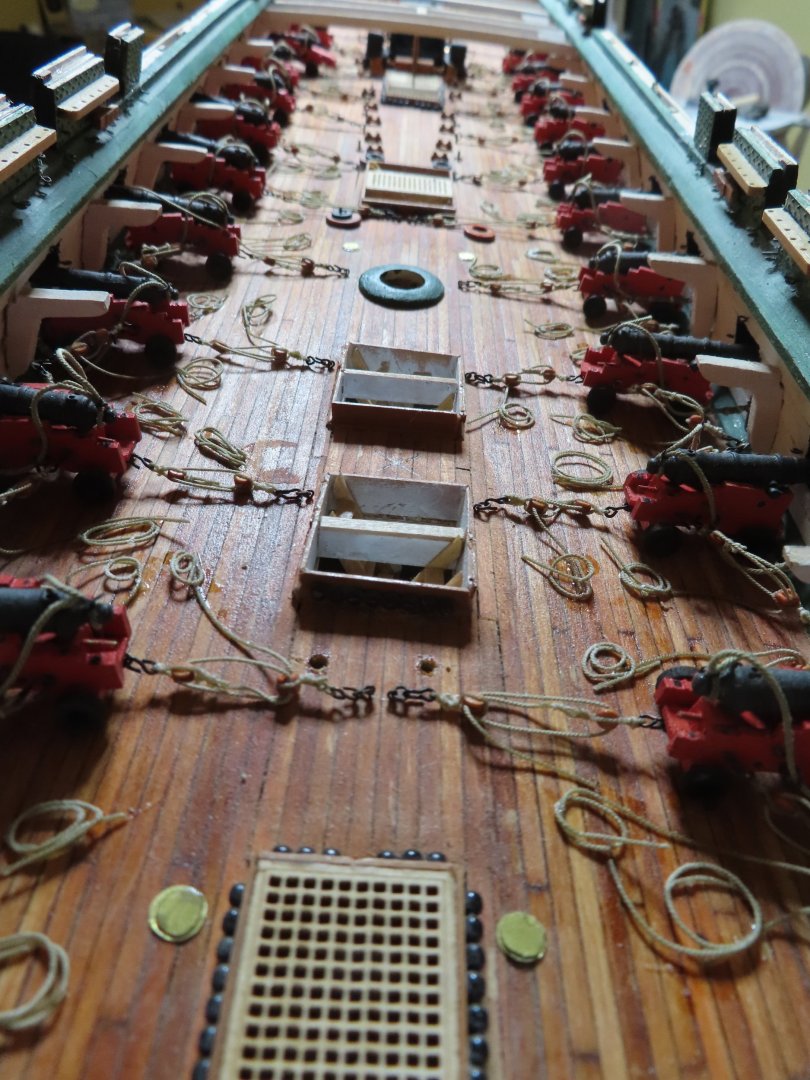
Getting back to the gun rigging, I decided to plunge in and complete the rigging once and for all. I just wanted to get it over and done with. Adding 22 fully rigged guns was no simple task. I made the following calculations and was staggered by what it revealed. From start to finish, adding eyebolts to the interior of the gun deck, to fabricating and assembling the gun trucks, and then rigging them, I got the following numbers: There are 235 separate parts per gun port or 5,170 parts for 22 fully rigged guns not counting brass blackening, painting, and do-overs. Most of these had to be fabricated from scratch. That breaks downs as follows: Gun & Truck = 26 pieces/gun = 572 pieces total Item Quantity Gun 1 Sides 2 Axials 2 Wheels 4 Transom 1 Breast Piece 1 Quion 1 Quion Handle 1 Quion Bed 1 Trunnion cap 2 Eyebolts 8 Rings 2 Gun Ropes (including excess waste) Ropes/gun: 10 cut pieces/gun = 220 pieces of rope total Recoil Rope. 1-6” piece 0.030” (0.76mm) dia./gun x 22 guns = 66 pieces = 132” = 11’ = 3.6 yds total Tackle Ropes w/coils 7” piece 0.018” (0.45mm) dia. + 1.5” (for double block)/tackle + coil = 8.5”/tackle + 1 rope coil x 3 tackles + coils/gun” = 7 pieces of rope/gun = 3 Tackles +3 coils/gun @ 25.5”/ gun = 154 pieces of rope = 561” = 47’ ~ 16 yds total for 66 tackles + 66 coils = 3,388 pieces total Rope Seizings/gun: = 21 rope seizings/gun = 462 seizings total = 3 yds thread total Recoil rope seizings 6 seizings/piece = 24” of thread = 2’ total/recoil rope Tackle seizings 5 seizings (@4”/seizings) /tackle = 20” thread/tackle rope 3 tackles/gun = 15 seizings = 5’ thread/gun = 3 yards thread total Note: rope coils made from excess rope and supplemented with additional rope 3 Tackles/gun = 6 blocks/gun = 132 blocks total 3/32” Single blocks 1/tackle @ 3 tackles/gun =3 blocks/gun = 66 blocks total 3/32” Double blocks 1/tackle @ 3 tackles/gun = 3 blocks/gun = 66 blocks total Block hooks 6/gun = 132 hooks total Gun Ports = 12 parts/port = 222 total Eyebolts: 10/port = 220 total: Recoil Rope eyebolts/port 4 = 88 total Tackle double eyebolts/port 2 = 44 total Idle eyebolts/port 3 = 66 total Deck tackle eyebolt 1 = 22 total Recoil rope bulkhead pins 2/port = 44 total All gun deck guns are now rigged!!! Whew!!! As I promised, an OSHA nightmare.

-
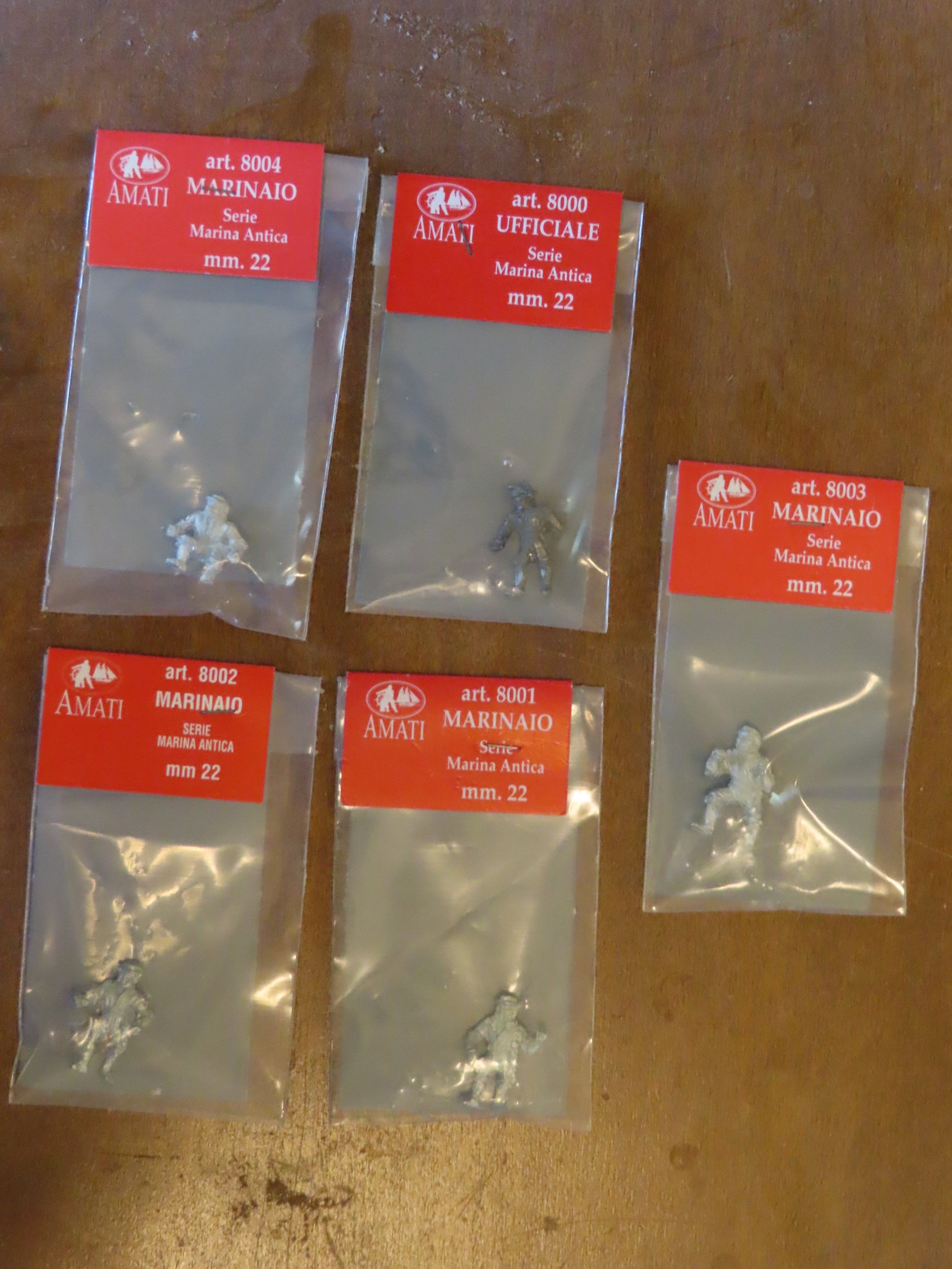
While continuing to work on rigging the guns, I took a diversion from this tedious task and once again went looking for figurines to be placed on the model later to add some scale. I added figurines to my 1:64 scale Rattlesnake which I finished in 2017 which worked out quite nicely and I want to do the same thing with the 1:76.8 Constitution which I started in 2017, but I’ve had no success finding any suitable figurines. For a typical 5’6” (165cm) tall man, I needed something around 0.841” (21.34mm) at scale. I was seriously considering modifying HO train figurines when I finally found five 22mm 18th (?) century sailor figures at Ages of Sail. I’ve checked this site before numerous times and even got the 25mm figurines for my Rattlesnake (1:64) from them some 8 or 9 years ago, but I never saw the 22mm ones until now. Strangely enough, the two sizes do not have the same figures, and are totally different from each other. Still, I immediately bought all five and it may be years (at my rate of speed) before I’ll need them. Who knows how long they will be available?


-
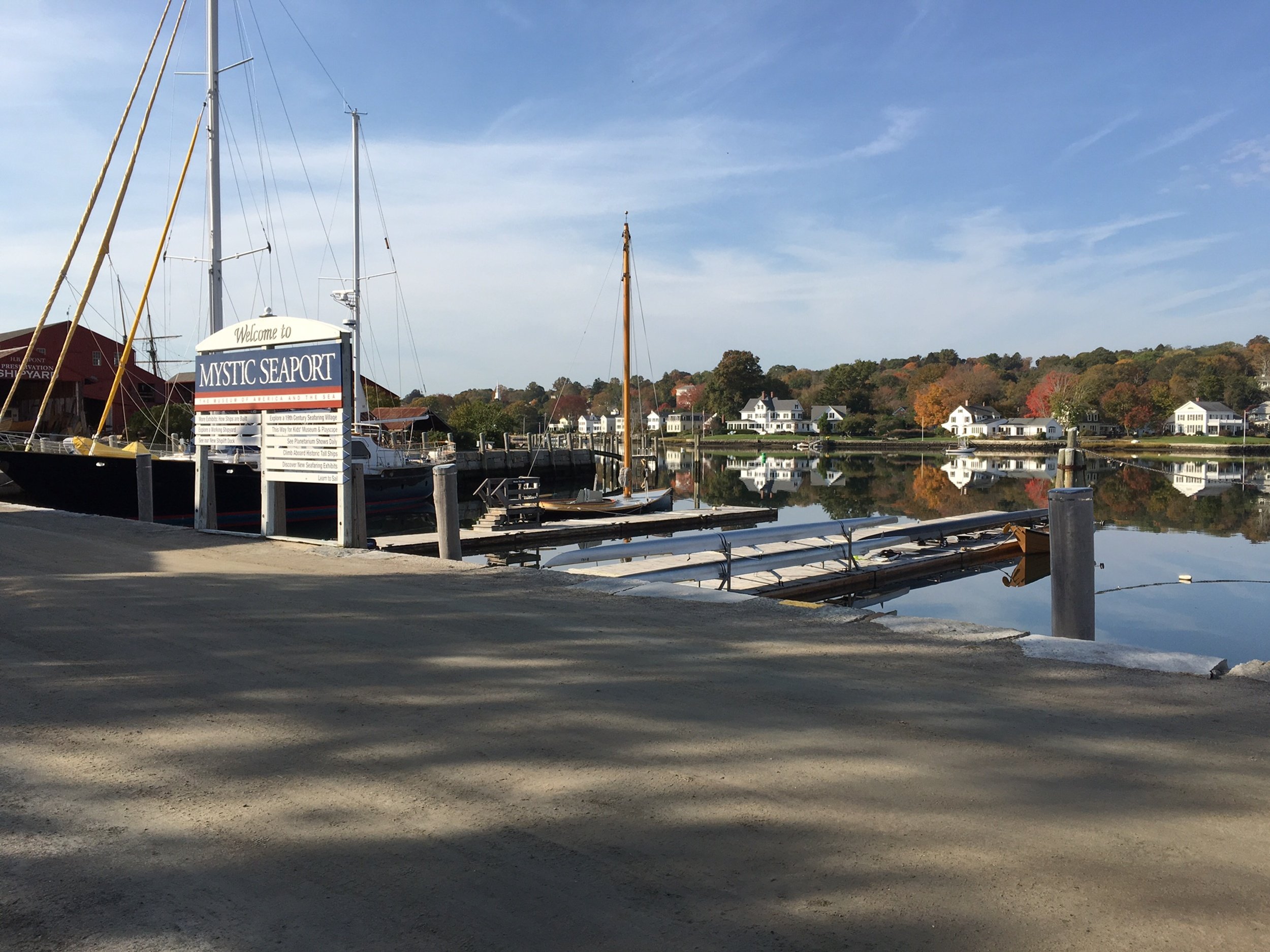
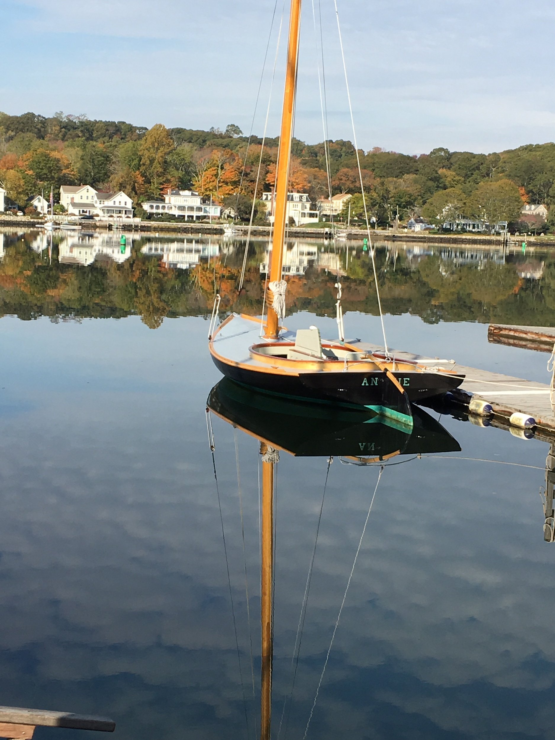
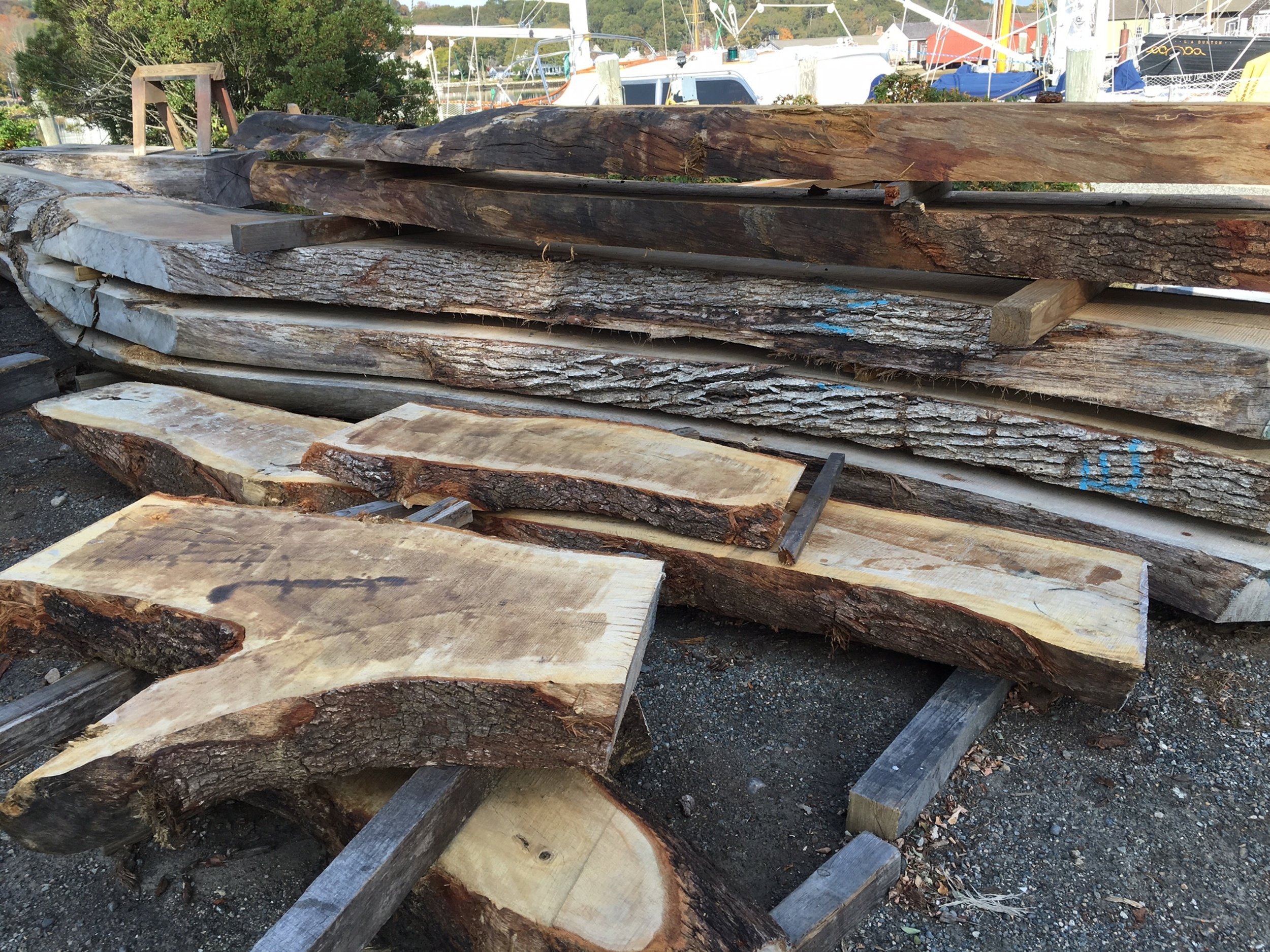
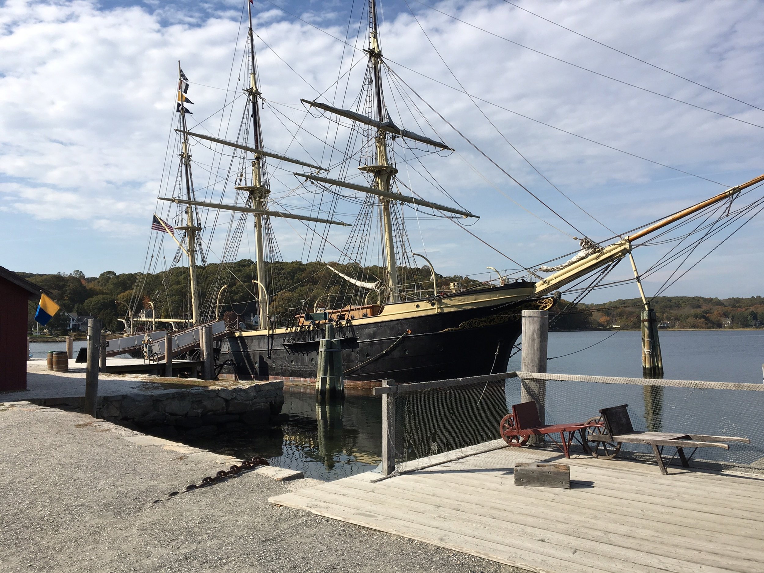
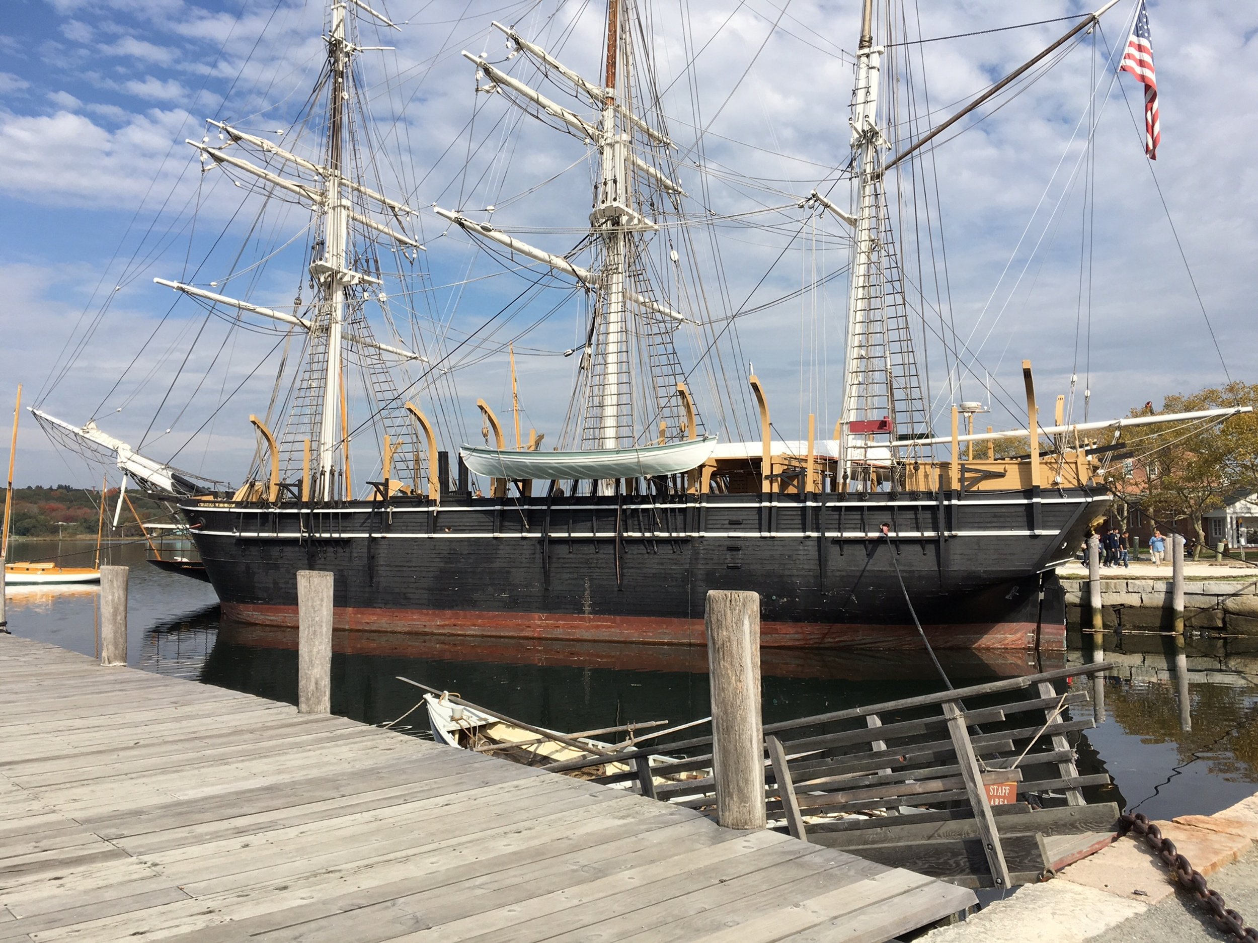
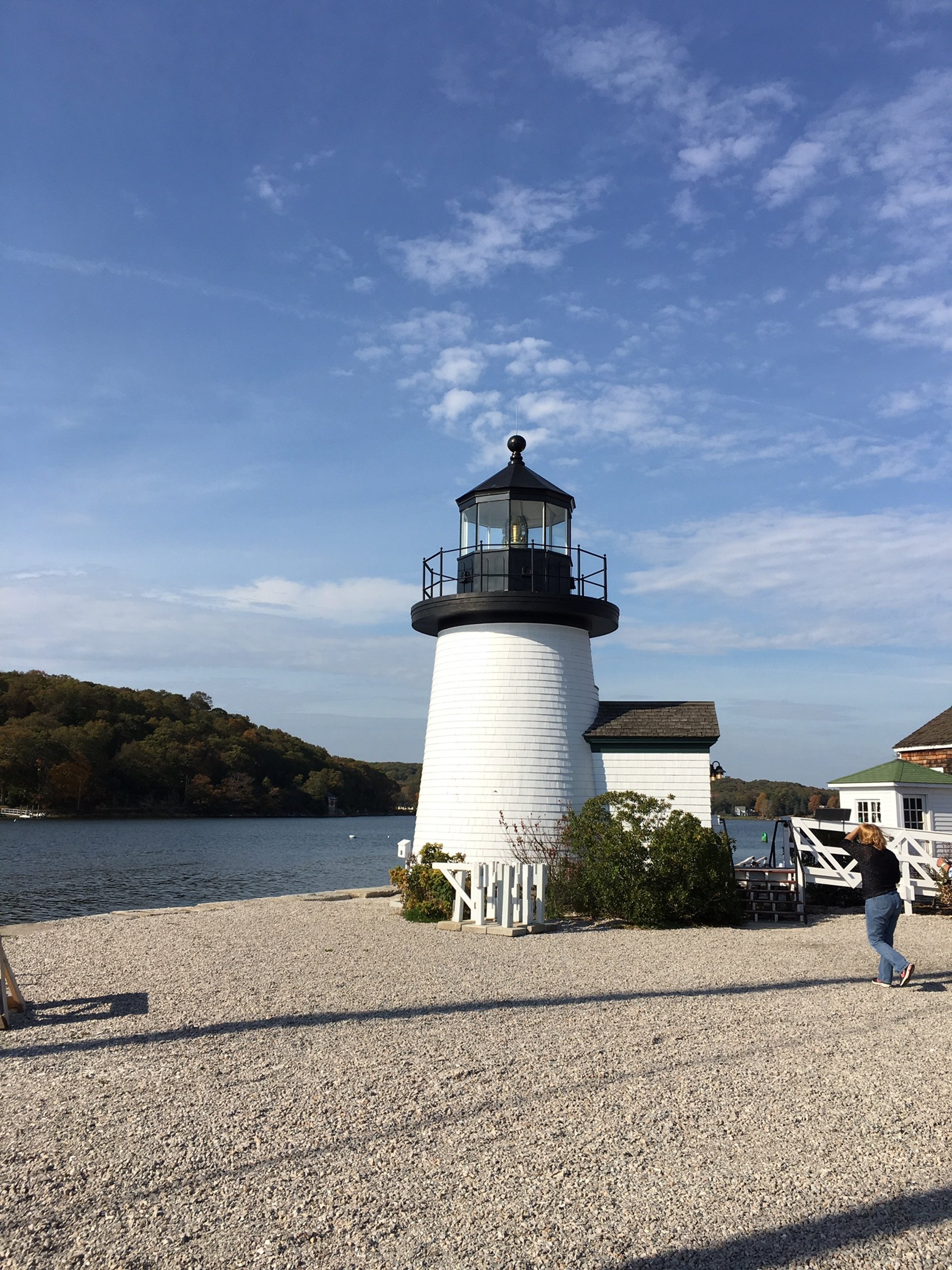
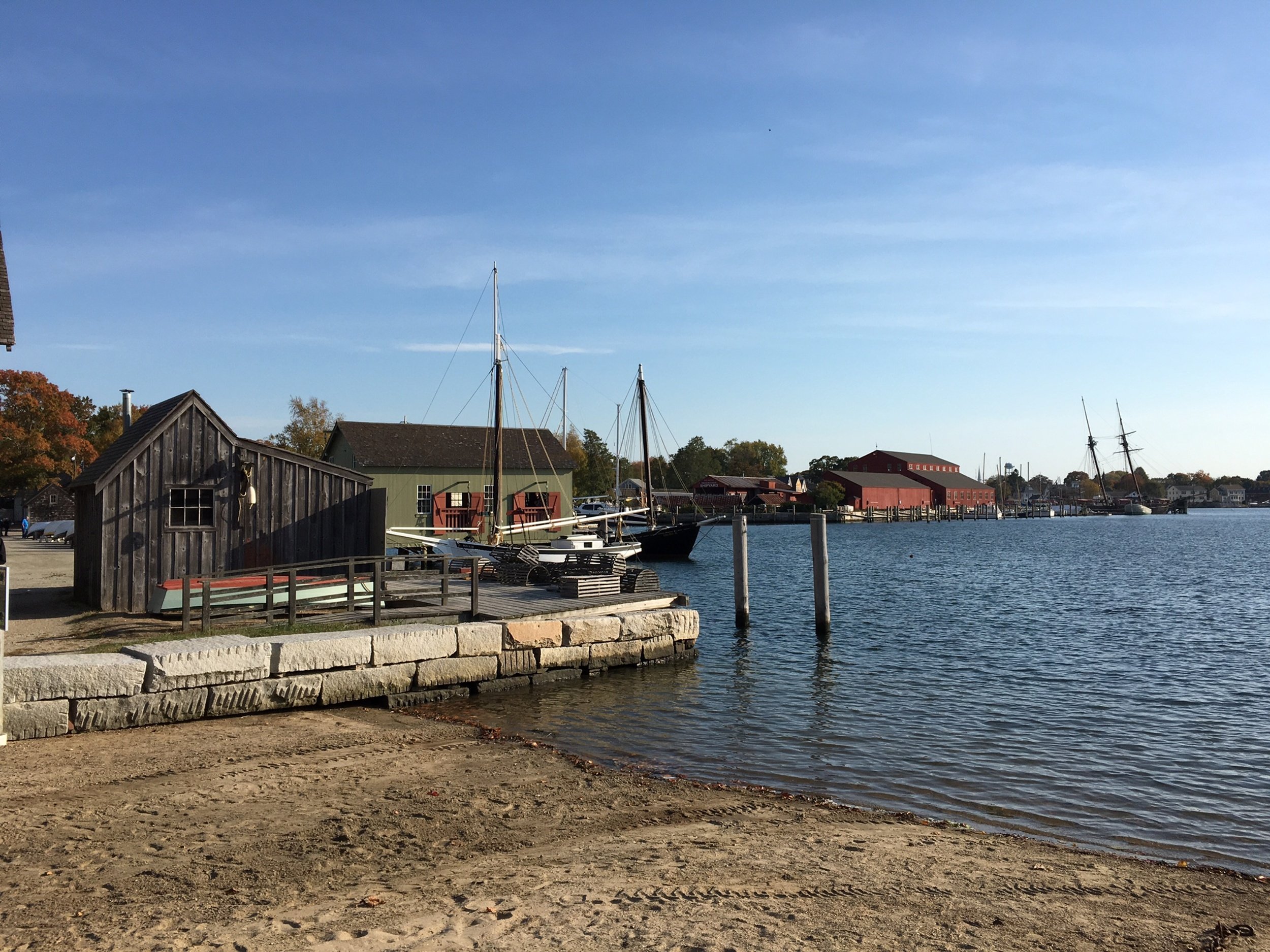
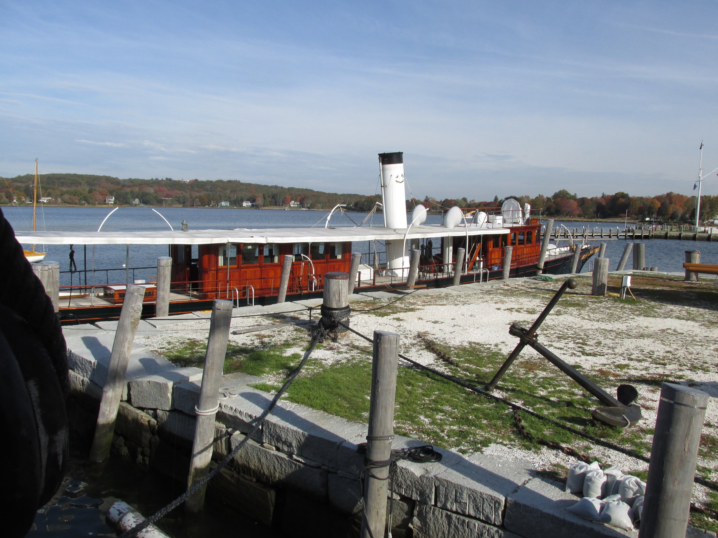
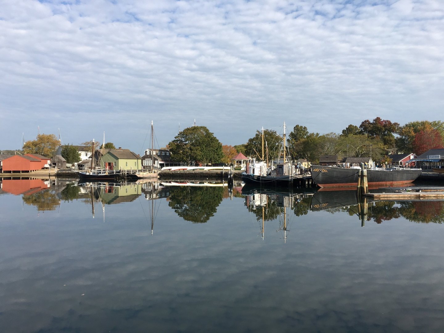
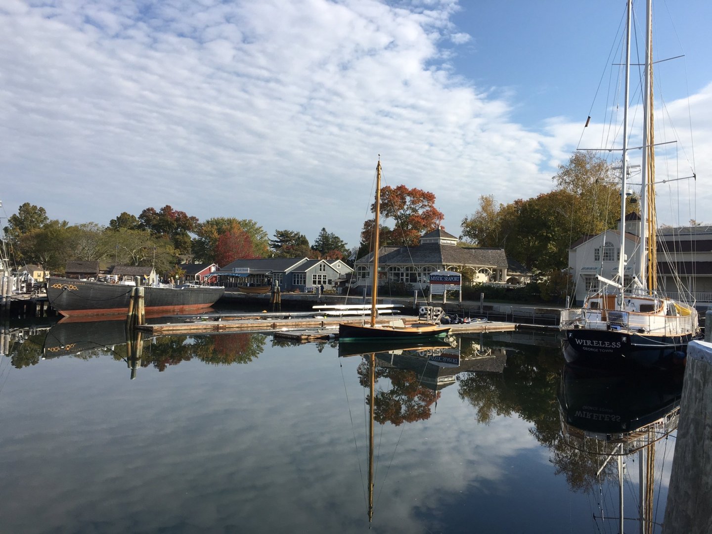
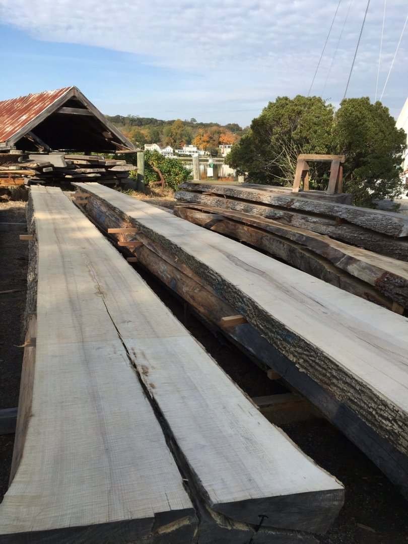
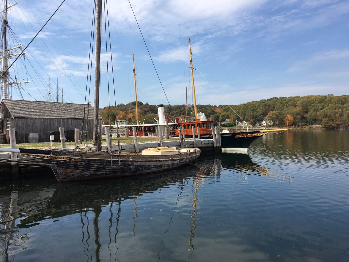
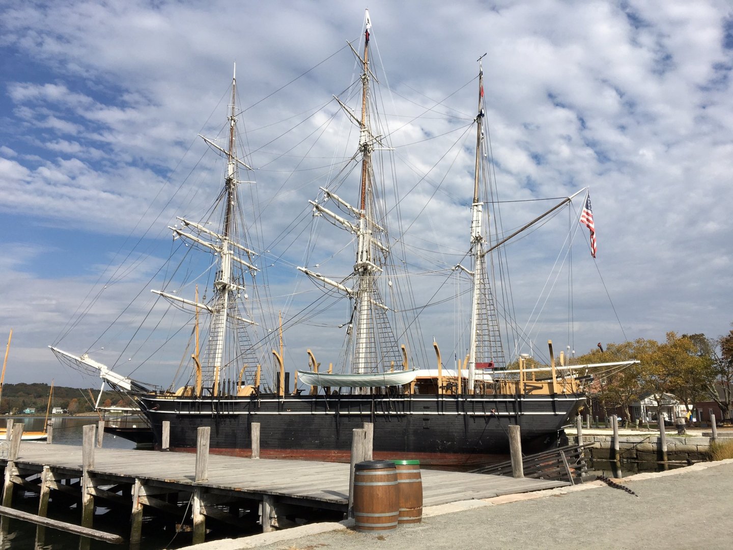
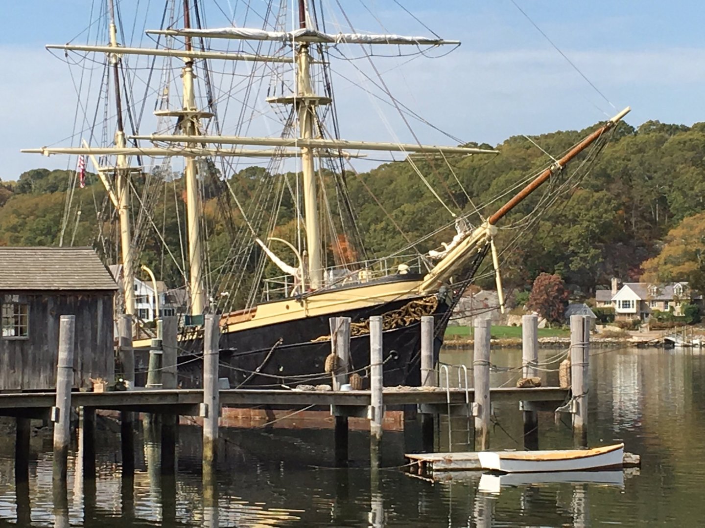
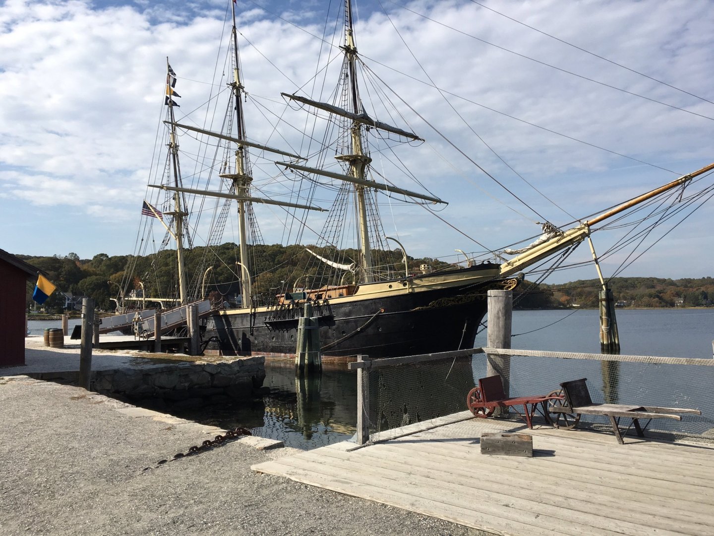
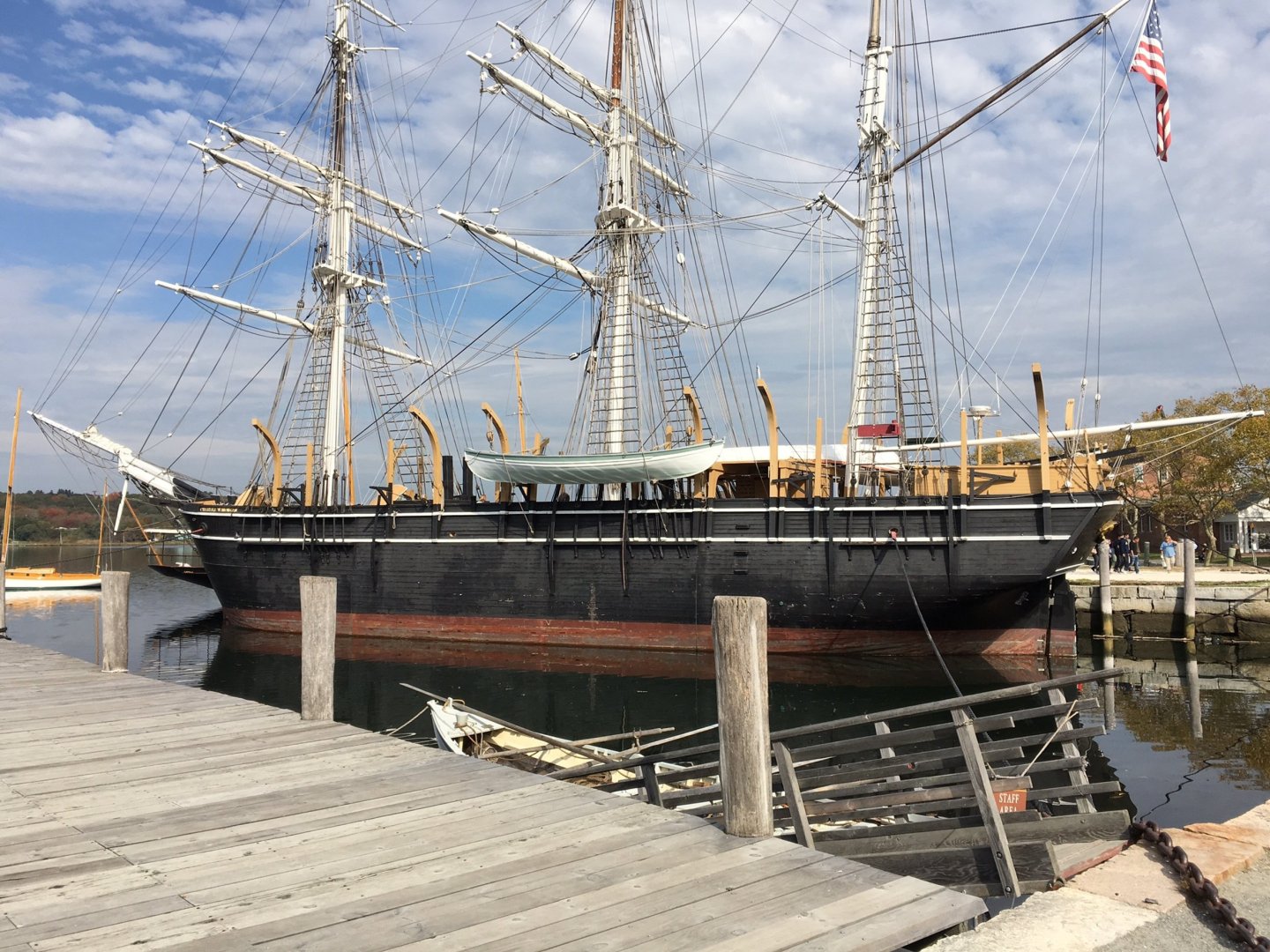
Thanks for the photos. I visited Mystic in 2015 for NRG convention. It was a wonderful time. I took a number of pictures and though you might want to add them to your collection Jon


-
USS Constitution by mtbediz - 1:76
JSGerson replied to mtbediz's topic in - Build logs for subjects built 1751 - 1800
Those pumps are coming along real nice Jon -
I grew up in the Boston area and left to follow the paycheck in 1977, but I was fortunate to have visited the Constitution a couple of times before I left. I now reside in South Carolina where the paychecks ended, and I retired. My last visit to the ship was in November 2015, just before her last restoration which ended in 2017. I have mentioned in several other builders’ logs, that I had been collecting photos of the ship starting a couple of years even before started building the model. They range from the very earliest images (1857) to the present. Obviously, most of the 4,000 odd images I have, accumulated from a variety of sources, are not of the post 2017 restoration. The few photos you posted of your recent visit to the ship are wonderfully taken. They are sharp, clear, and well composed. (I was a serious amateur photographer in an earlier life). So, if I may impose on you to share any more photos, it would be greatly appreciated. If you (or anyone else) need an image(s) of something and can’t find it on the internet, I may have the image you’re looking for. Most times when you put in a search request for “A.” you may also get “B,” or “C.” If they are remotely relevant to the ship, I collect them because should I need to find them later, searching for “B” or “C” may not give me those particular images. Hence, I’ve got some rare or difficult to find detail images. If I may offer one critique with the photo of painting the waterways, if possible try to make sure you background is unobtrusive. Now I know you are a food and wine aficionado.🤫 Keep up the good work. Jon
-
USS Constitution by mtbediz - 1:76
JSGerson replied to mtbediz's topic in - Build logs for subjects built 1751 - 1800
Now I know, thanks! Jon -
USS Constitution by mtbediz - 1:76
JSGerson replied to mtbediz's topic in - Build logs for subjects built 1751 - 1800
Looks great! How did you tie off the rope at the bottom of the stairs as access is quite limited. If it's doable for me, I may attempt it myself. Jon -
USS Constitution by mtbediz - 1:76
JSGerson replied to mtbediz's topic in - Build logs for subjects built 1751 - 1800
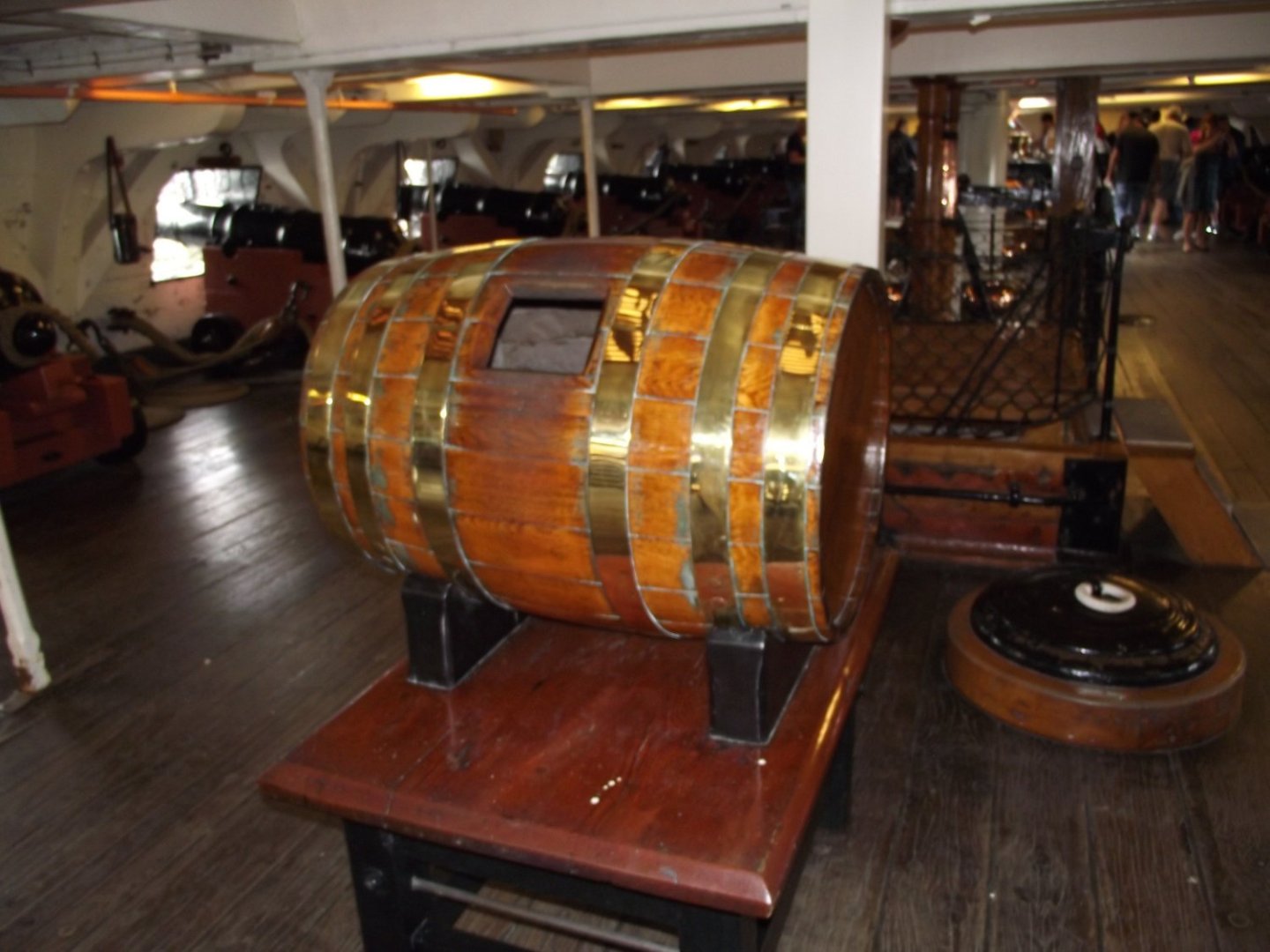
Ok, here's what I got. The first picture is a "Harness Cask," (I don't know how "harness" is defined on a ship) the second is the "Grog (watered down rum) Tub," and the third is the "Scuttlebutt" (contains water). I do have US Navy plans of the scuttlebutt and the harness cask should anyone want them. Jon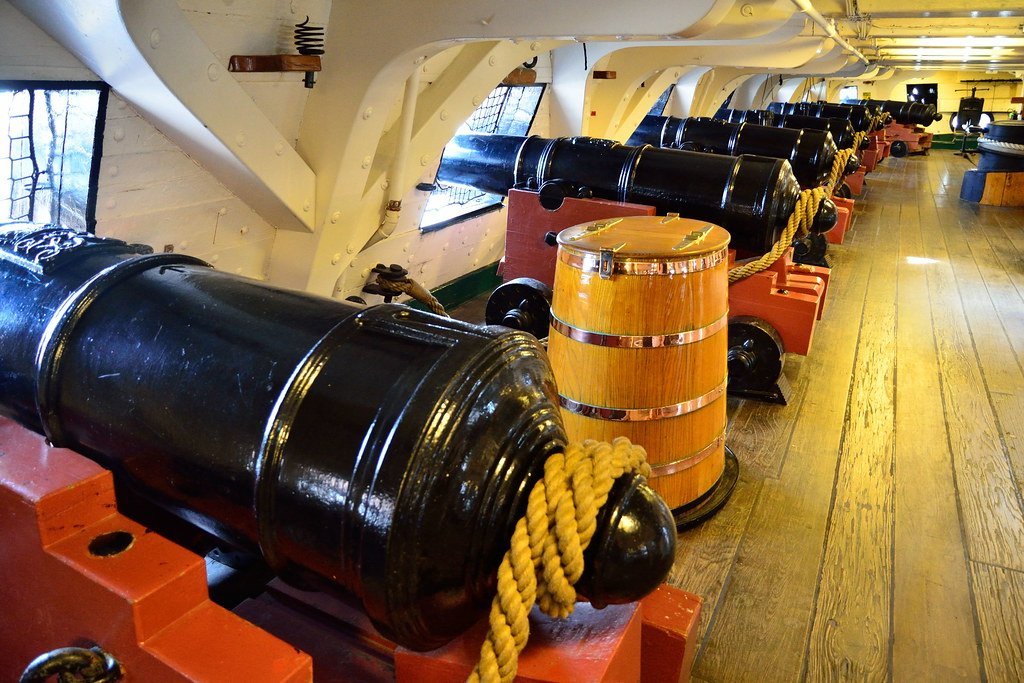

-
USS Constitution by mtbediz - 1:76
JSGerson replied to mtbediz's topic in - Build logs for subjects built 1751 - 1800
She was deployed October 21 1797. -
USS Constitution by mtbediz - 1:76
JSGerson replied to mtbediz's topic in - Build logs for subjects built 1751 - 1800
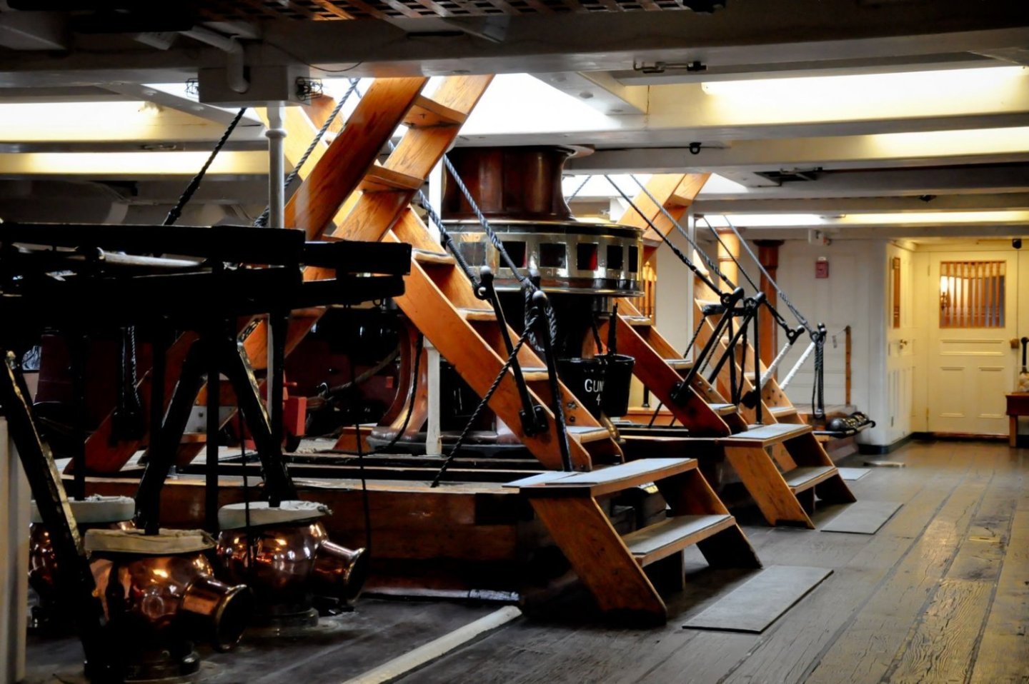
I'm not surprised those auxiliary beams inside the ship obscure the gun deck view. This war ship, although made of wood (obviously), was built to take punishment. If you look at the photo below from the 1873-77 restoration, you can't even see inside the ship with her hull planking removed. The hull frames were so close to each other, the ship looks solid. To take a phrase from an old Timex watch advertising slogan, "it takes a 'licken' and keeps on 'ticken,'" No wonder they called her "Old Ironsides." Jon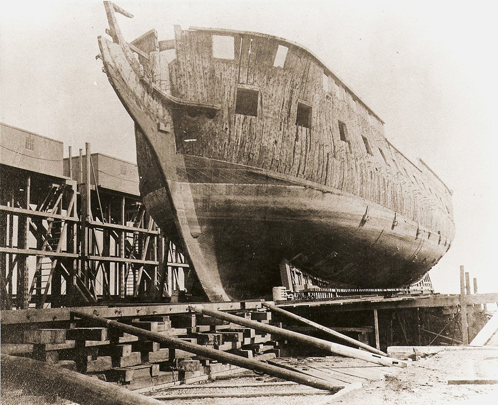
-
USS Constitution by mtbediz - 1:76
JSGerson replied to mtbediz's topic in - Build logs for subjects built 1751 - 1800
Glad you came to that conclusion although I love your beautiful workmanship on those beams. Jon -
Magnets or no magnets, your planking looks great! Jon
-
USS Constitution by mtbediz - 1:76
JSGerson replied to mtbediz's topic in - Build logs for subjects built 1751 - 1800
Looks like the real ship. Nice work! Jon -
USS Constitution by mtbediz - 1:76
JSGerson replied to mtbediz's topic in - Build logs for subjects built 1751 - 1800
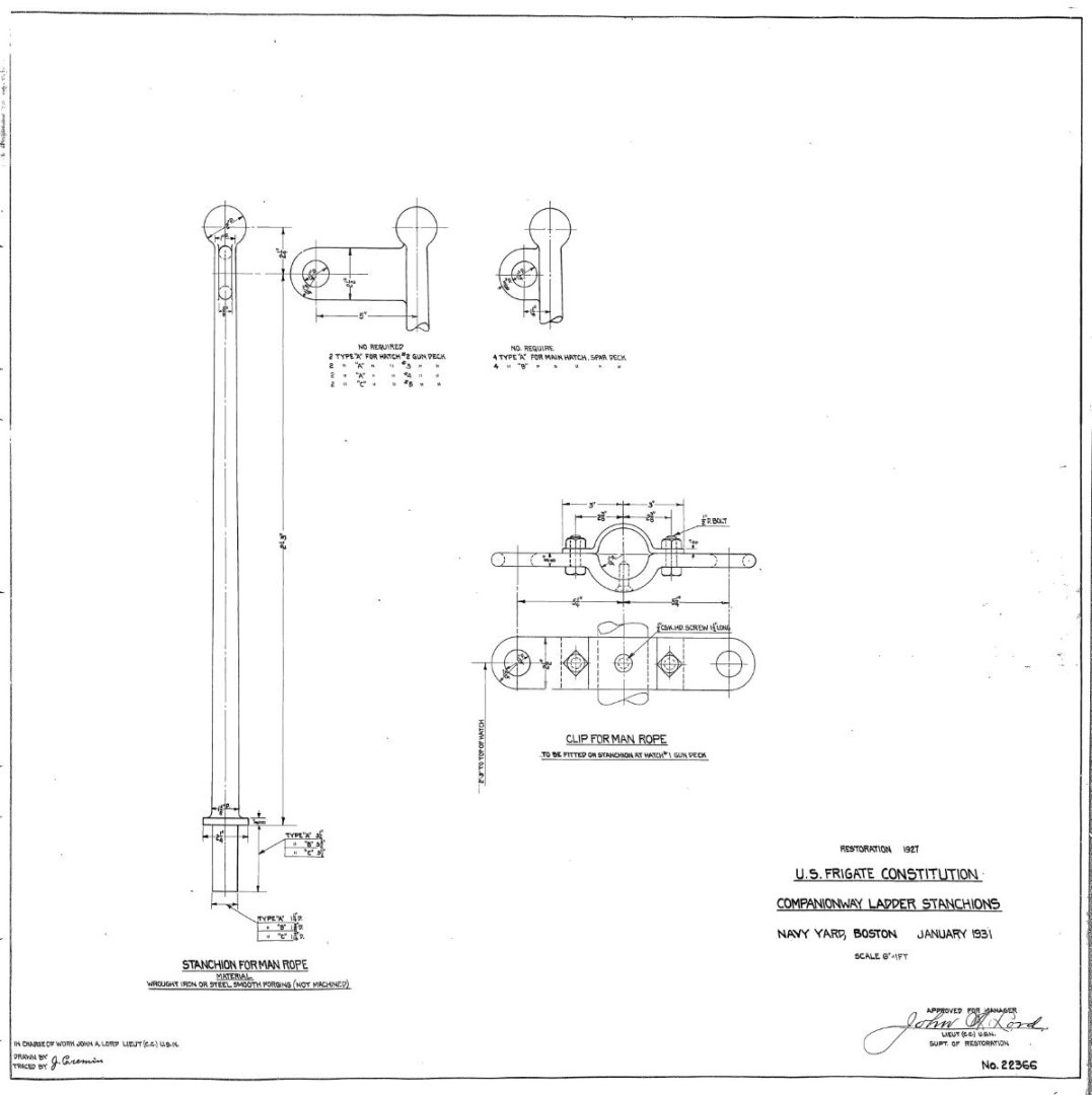
I initially added the hand ropes on the ladders going from the gun deck to the pseudo berth deck, or at least I tried. Over time they have all been knocked off due to the weak bond of the very limited gluing area surfaces. Because of the limited viewing and now inaccessible areas at the bottom of those ladders, I won't be replacing the hand ropes. I'll probably try again for the ladders going to the spar deck, We'll see what happens. Jon -
USS Constitution by mtbediz - 1:76
JSGerson replied to mtbediz's topic in - Build logs for subjects built 1751 - 1800
Now the question is, are the hand ropes for the tourists or were they part of the ladder the crew would have used in 1812? For example, the netting around the gun deck gun ports is to prevent idiot tourists from falling out of the ship. It is something I won't add to my model. Jon -
USS Constitution by mtbediz - 1:76
JSGerson replied to mtbediz's topic in - Build logs for subjects built 1751 - 1800
GGibson, well, let's see what I can do for you. Jon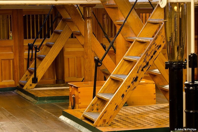

-
USS Constitution by mtbediz - 1:76
JSGerson replied to mtbediz's topic in - Build logs for subjects built 1751 - 1800
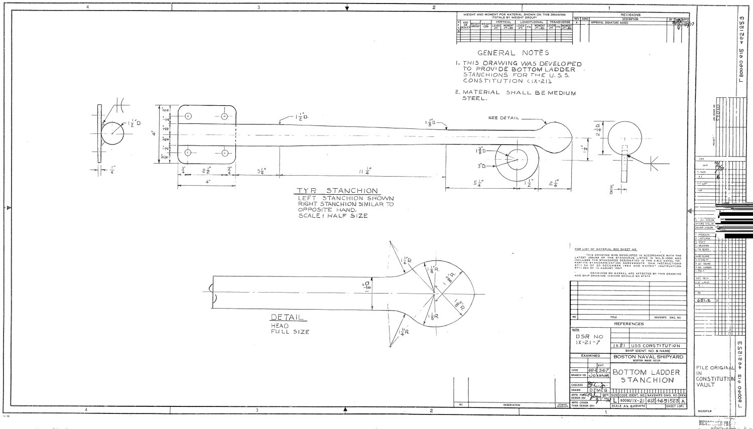
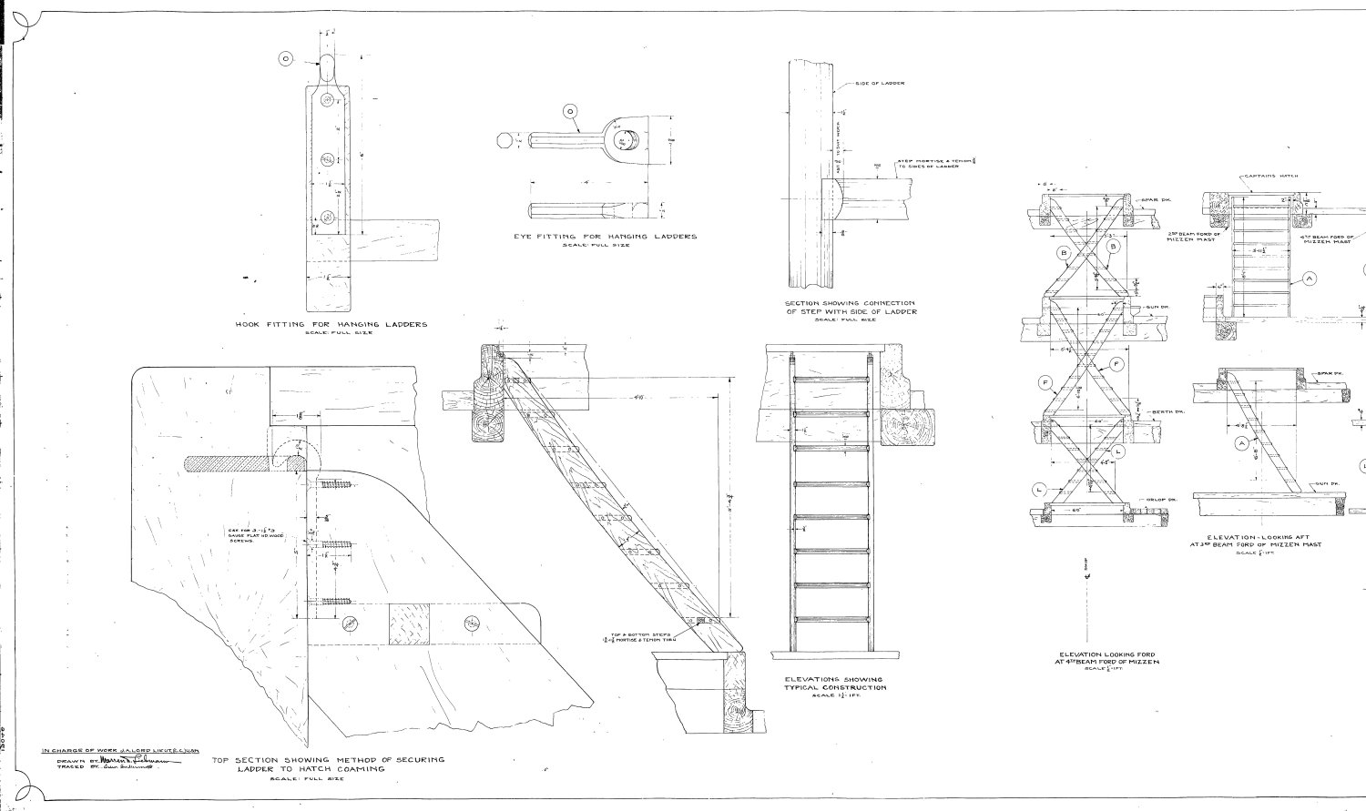
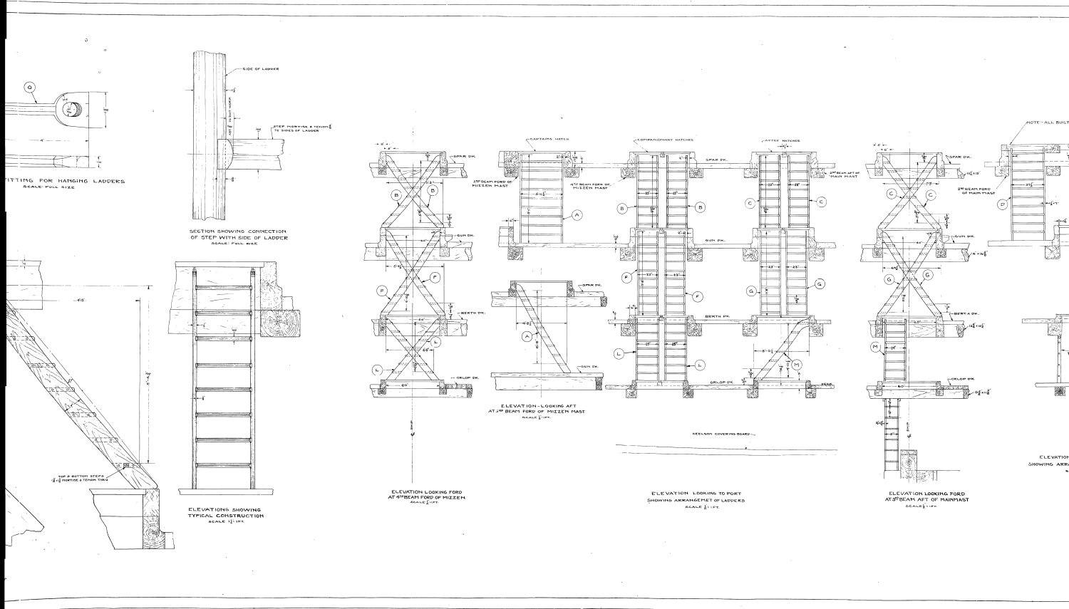
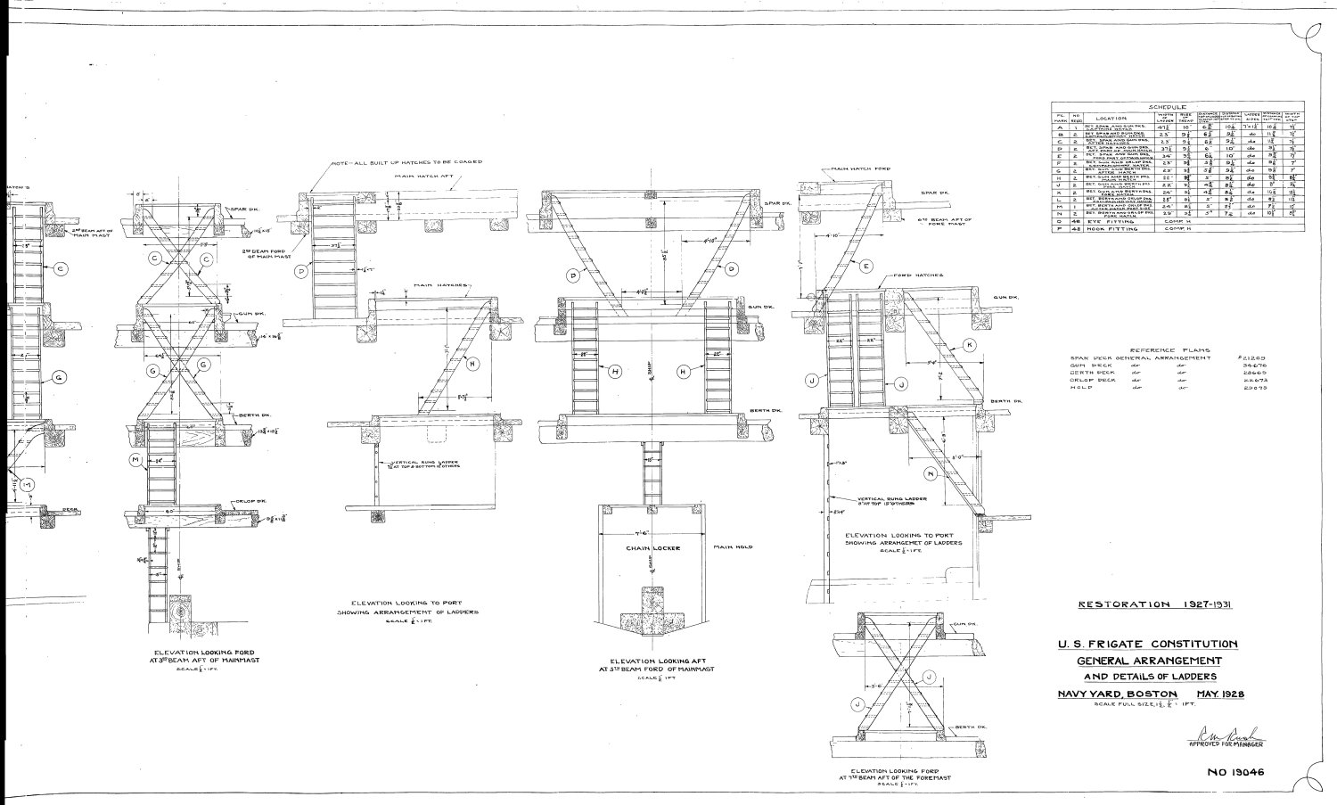
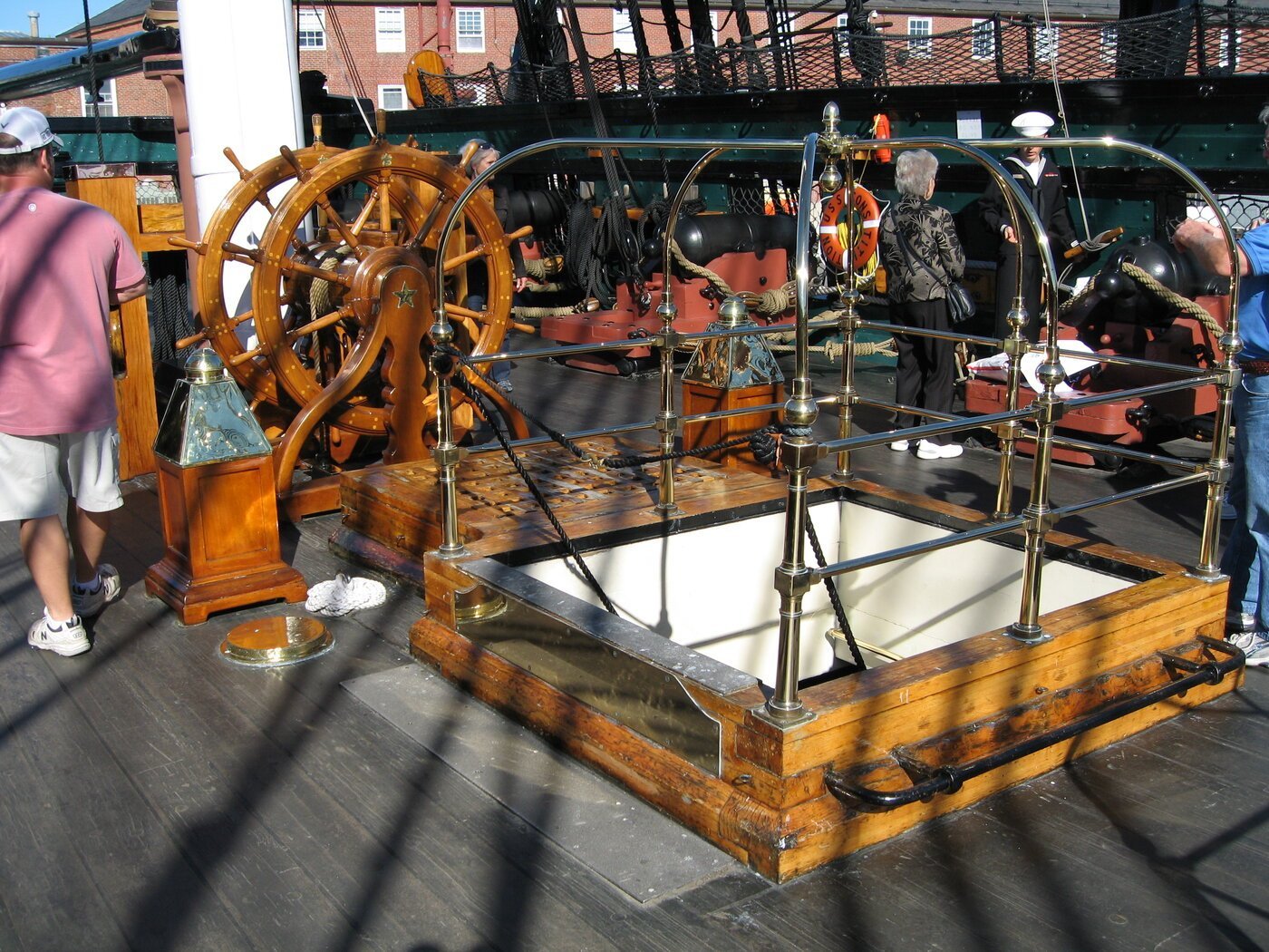
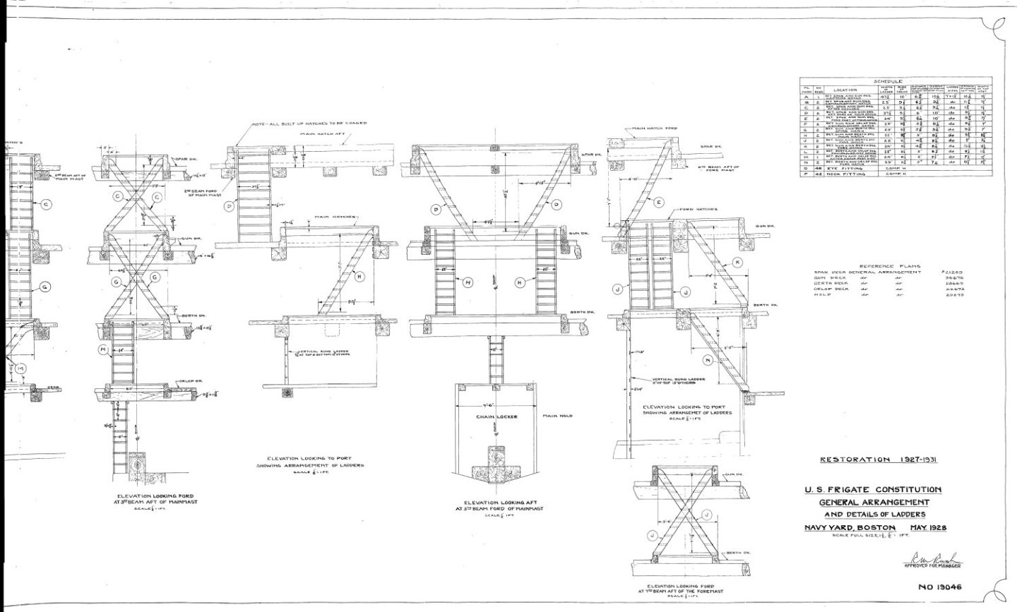
After studying your beautiful ladders, I think I may have discovered an unfortunate measuring error. Per the attached US Navy plans, the ladders extend into the grating which extends above the deck. Your ladders stop at the top of the floor beams. See attached plans. I really hate to mess up your fine wood work.🫤 Jon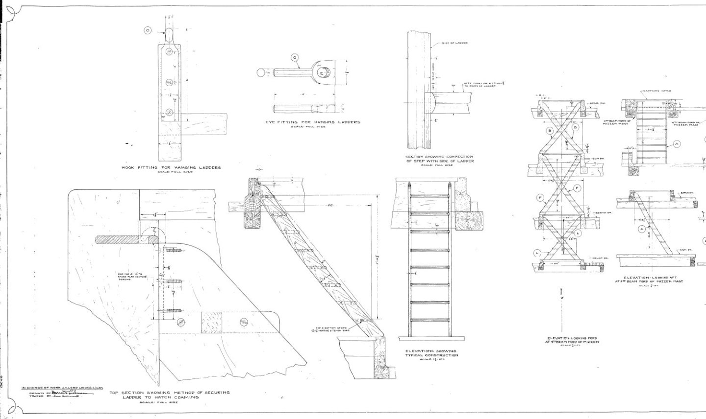

-
USS Constitution by mtbediz - 1:76
JSGerson replied to mtbediz's topic in - Build logs for subjects built 1751 - 1800
Very nice ladders. They have been one of the banes of my modeling experience. I've tried different methods, tools, and jigs and have been not been happy with any of my results. I'll have to give your obvious successful method a try when the time comes. Jon -
USS Constitution by mtbediz - 1:76
JSGerson replied to mtbediz's topic in - Build logs for subjects built 1751 - 1800
That chain worked out very nice for you. Jon -
Thanks all for the kudos!🤗 Greg, I got that clamp from Micro Mark. I've had for a number of years, but rarely had a chance to use it. I'll probably use it again once I get to fabricating the various ship's hold framings on the spar deck.