JSGerson
-
Posts
2,633 -
Joined
-
Last visited
Content Type
Profiles
Forums
Gallery
Events
Everything posted by JSGerson
-
 g8rfan - Actually, I have looked at HO figures, but I've never transformed a human figure's clothing/look into something that reasonably looked like someone else. I don't have that artistic talent; but it's not out of the realm of possibilities yet. I've got a long way to go before I'll could use them, so I still have time to consider other possible solutions. Thanks though, for the suggestion.
 -
USS Constitution by mtbediz - 1:76
JSGerson replied to mtbediz's topic in - Build logs for subjects built 1751 - 1800
DAR, we may be both correct. I checked the US Navy plans and the wale does exist but is not as pronounced on the surface of the hull as the MS plans make it out to be. At best, the wale bumps out at its thickest point about 3.5" from the hull or about 3/64 at scale." and even that change is not as abrupt as the MS plans show. To see that fine detail in very old images is unlikely.
-
USS Constitution by mtbediz - 1:76
JSGerson replied to mtbediz's topic in - Build logs for subjects built 1751 - 1800
The simple reason is that it is thicker on the actual ship as well as it is on the plans. I'm no expert on ship design, but I assume the added thickness is for added strength when docking and bumping into things. These ships are often rolled on their sides for maintenance too. See foreshortened image below.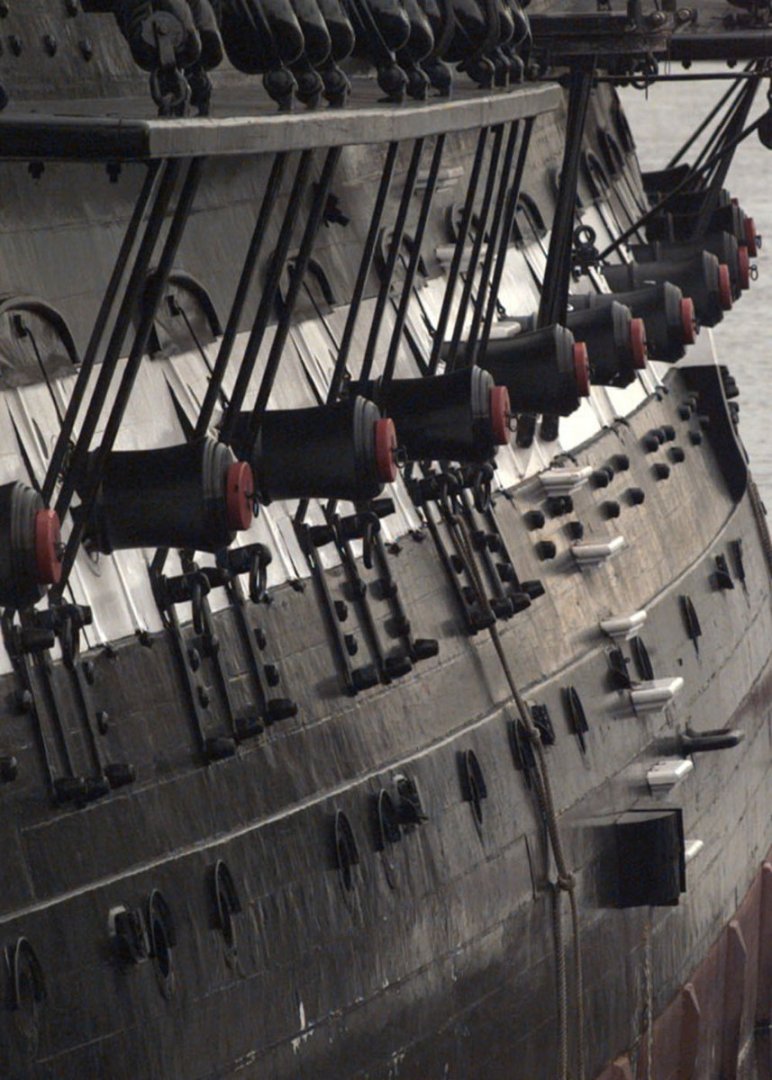
-
USS Constitution by mtbediz - 1:76
JSGerson replied to mtbediz's topic in - Build logs for subjects built 1751 - 1800
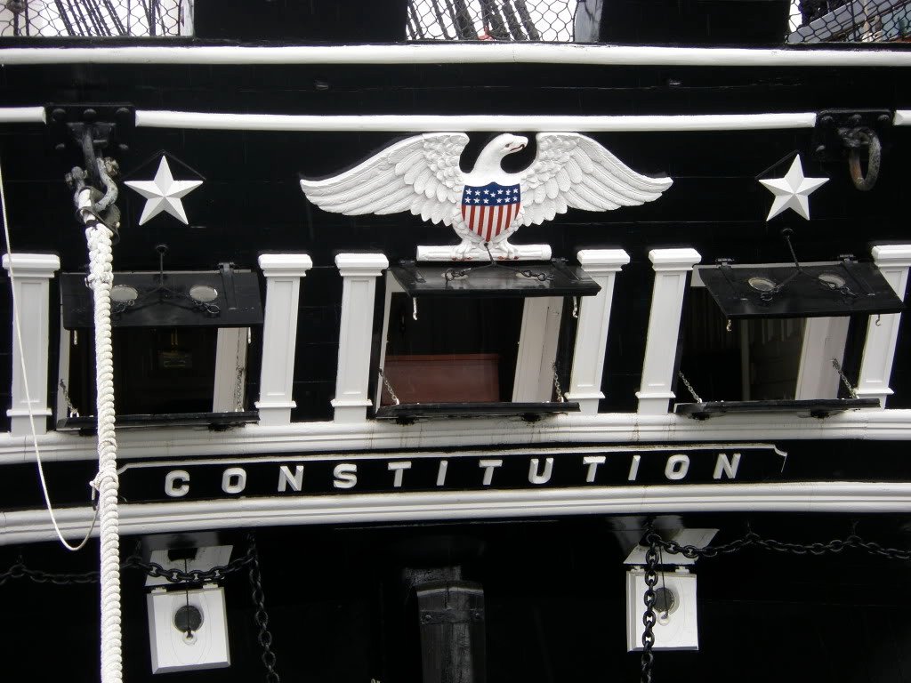
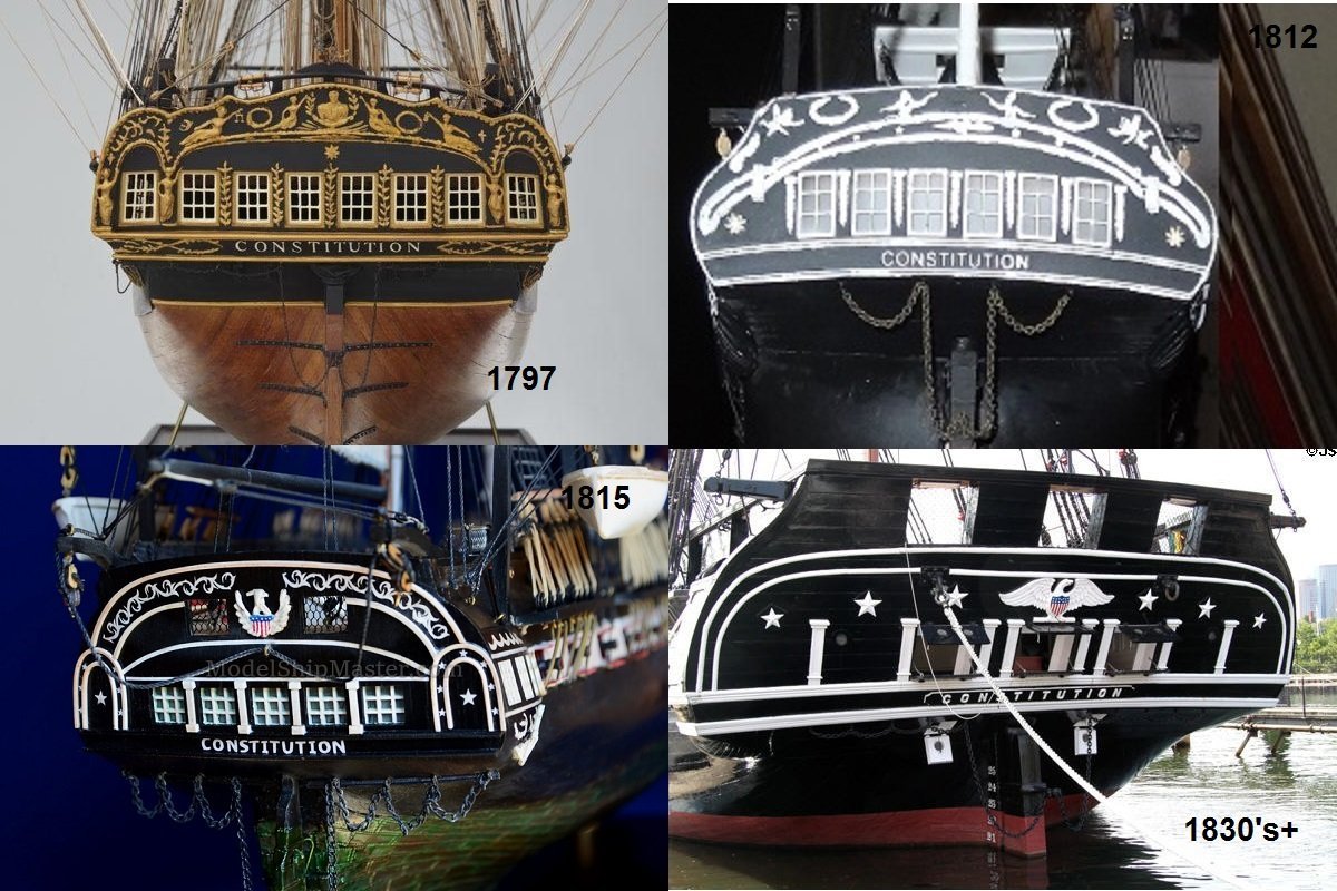
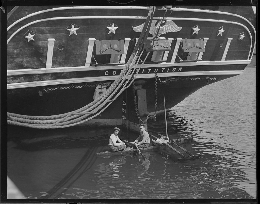
The transom like other parts of the ship changed over the years, so I hope these images help. The close-up image is present day, The image with windows sashes was 1914. I believe the sashes were removed after the 1927 renovation as seen in the 1934 image with two guys in a row boat. I also gave you a historic montage as to some of the changes that took place. Jon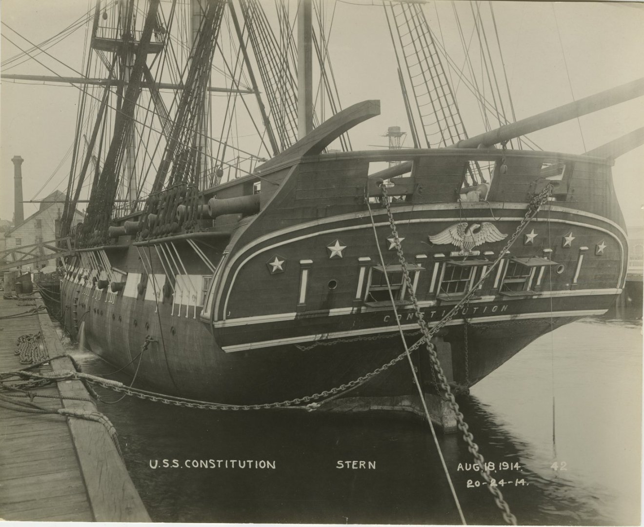
-
USS Constitution by mtbediz - 1:76
JSGerson replied to mtbediz's topic in - Build logs for subjects built 1751 - 1800
I've always had a hard time bending wood without kinking, cracking, or breaking. It was for those reasons I used the very flexible Styrene plastic on my model for the curved modeling. However, I wasn't too pleased with the mediocre results. The CA glue made the plastic brittle. What wood did you use and how did you soften it up to bend it? BTW, wonderful job! Jon -
Now the fun part begins!🙃
-
A lot simpler method than I did and probably just as effective to the typical observer. Looks good so far. Jon
-
I've spent many hours researching through my photo library, Google, a multitude of build logs (both finished & in progress) and yet for some reason, my model doesn't look any different than it did before I started hours ago. Is that considered time spent building the model? Jon
-
Gregg, I'm not certain which build log website you could not find so here are the three sites we have been talking about: Usedtosail xKen Modeler12
-
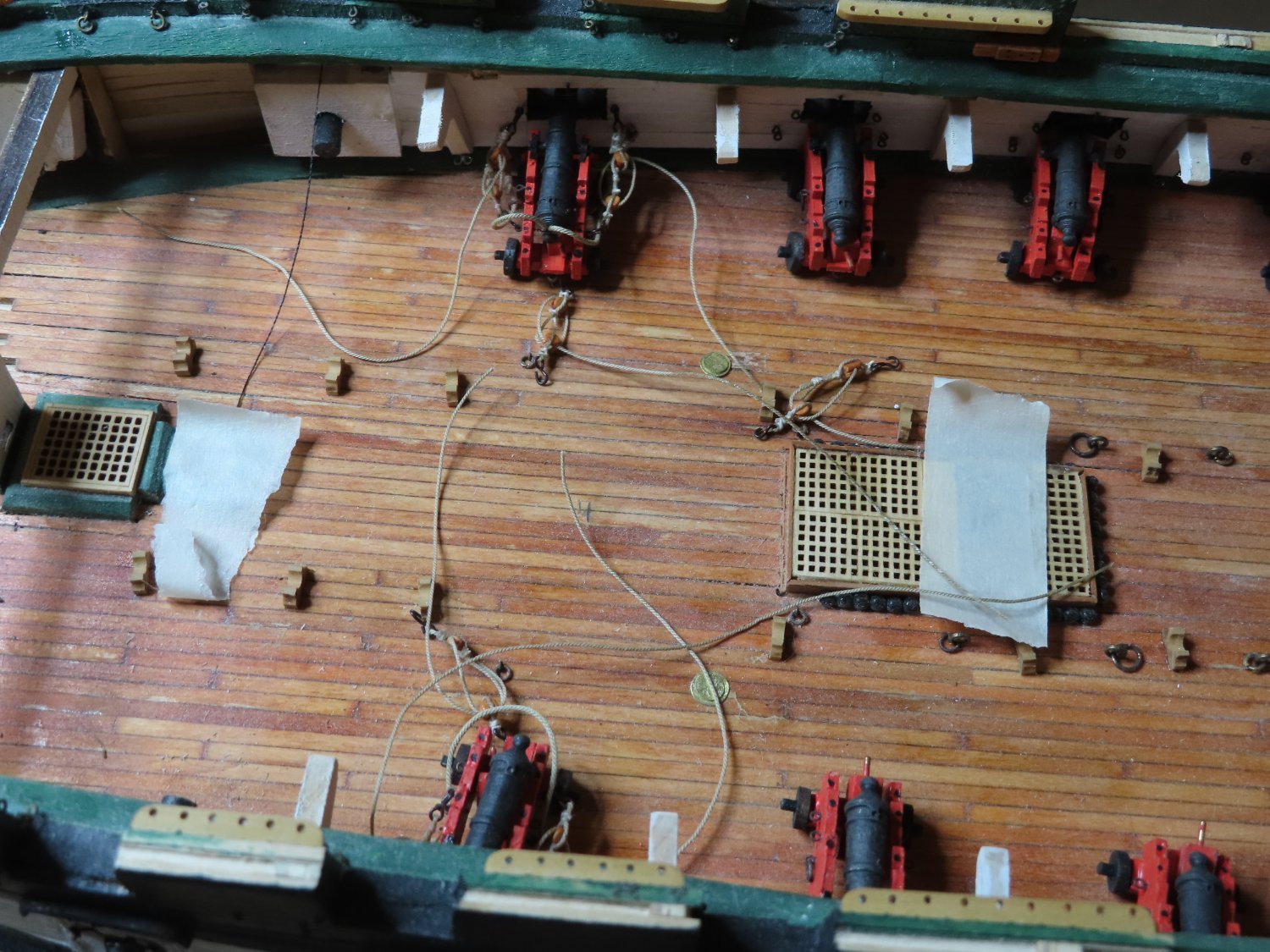
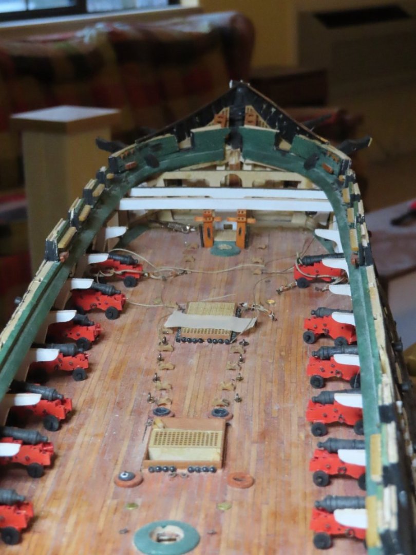
Ken, A lot of builders rigs their guns minimally for aesthetics. Things look nice when they are neat. I want the detail, so by the time I'm finished with the gun deck, I expect it to be an OSHA nightmare 😁. How those guys back then worked around all those ropes, chains, clutter, noise, smoke, etc. and still were able to conduct ship warfare effectively enough to never lose a battle is amazing. Jon
-
I believe, that for the most part, it's personal preference. He may have believed that delaying planking the rest of the model at this point may avoid unnecessary repairs later on due to the delicate nature the hull copper cladding. Because I've added the gun deck among other details to my model, I've bounced around his instructions and even substituted other builder's methods I've read about in their logs. Mr. Hunt does a great job for some details, and skips lightly over others. If you follow him religiously, you will end up with a decent model, but you may wish you had done something differently looking at other builds. I use his practicum as a guide, and as a bible. There is no real right or wrong method, just what works for you. Jon
-
Hi Ken. long time, no post. It's great to learn you're back at the shipyard. I look forward to your forthcoming posts. For such physically small items, there are a lot of details to juggle when making all those gun carriages. Just remember, it's a hobby, so have fun. Gregg, you are correct, it's not a race. I've been working on this model since 2017 and was researching it even earlier. I still haven't seen the finish line! Jon
-
Nice save. In your situation, I've would have handled it in the exact same manner. Out of curiosity, what kind of wood is your hull planking made of? It does present a unique visual pattern. Will it eventually be covered with a second layer of planking and/or paint and copper plate(?). Jon
-
much appreciated, Gregg
-
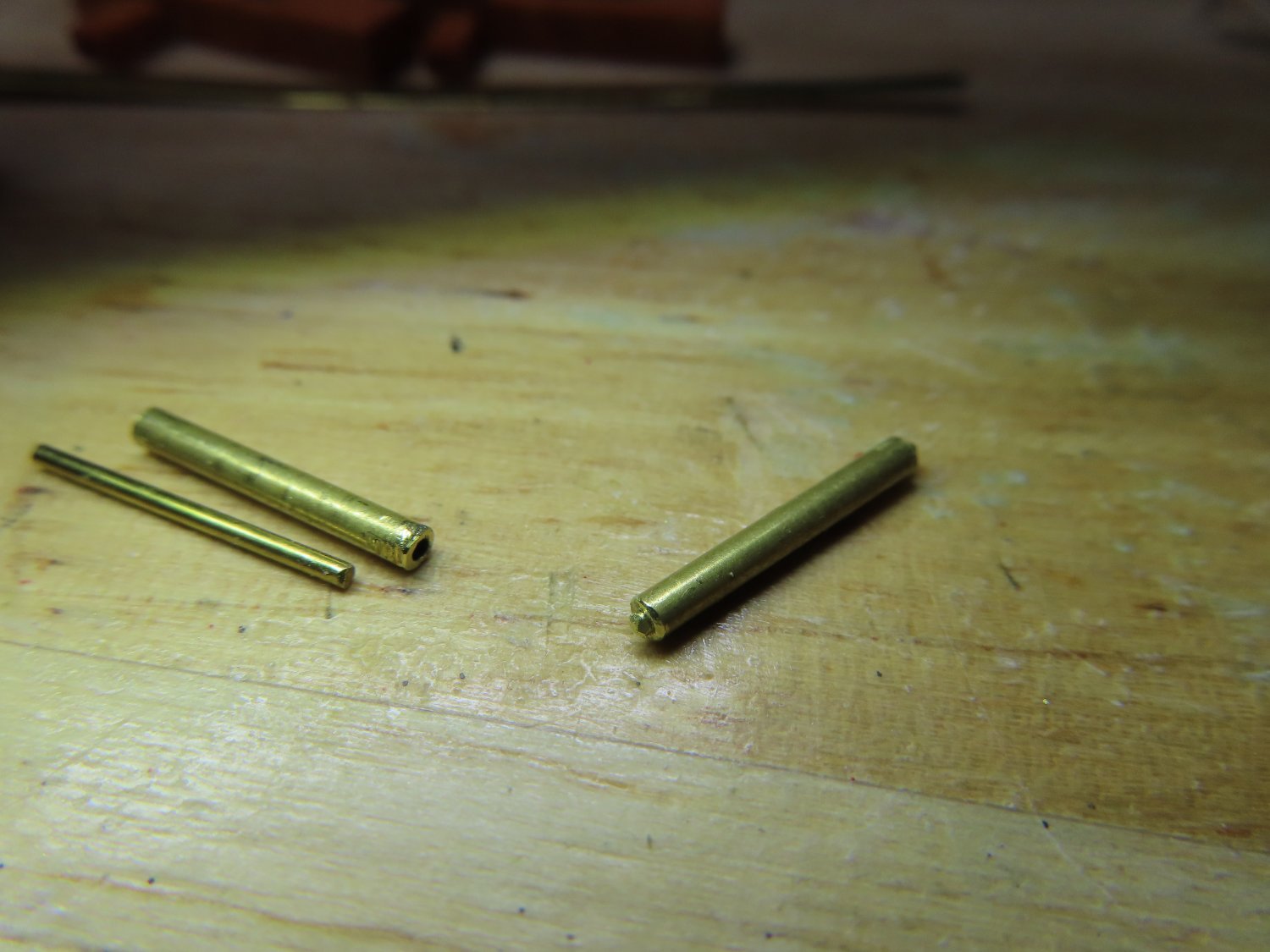
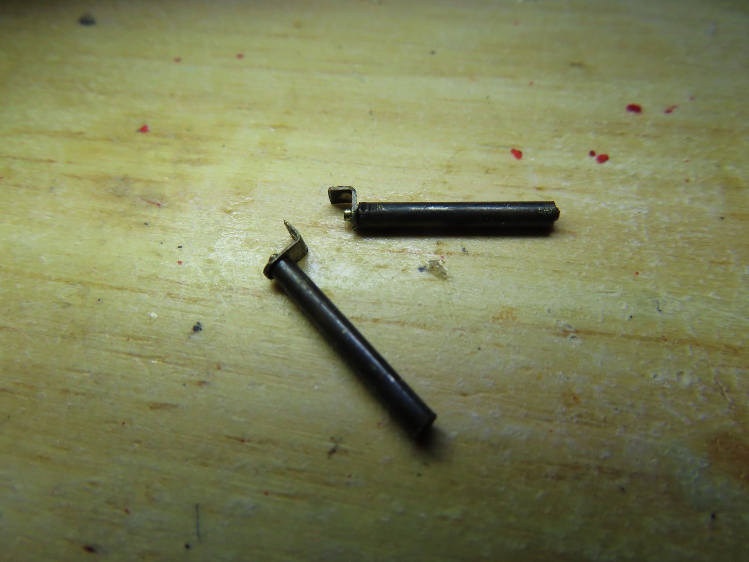
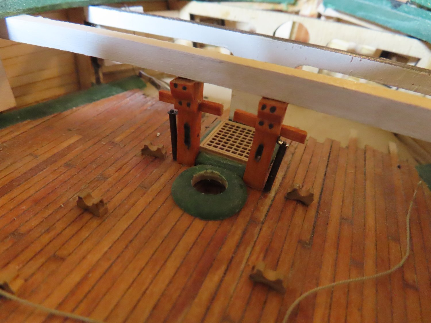
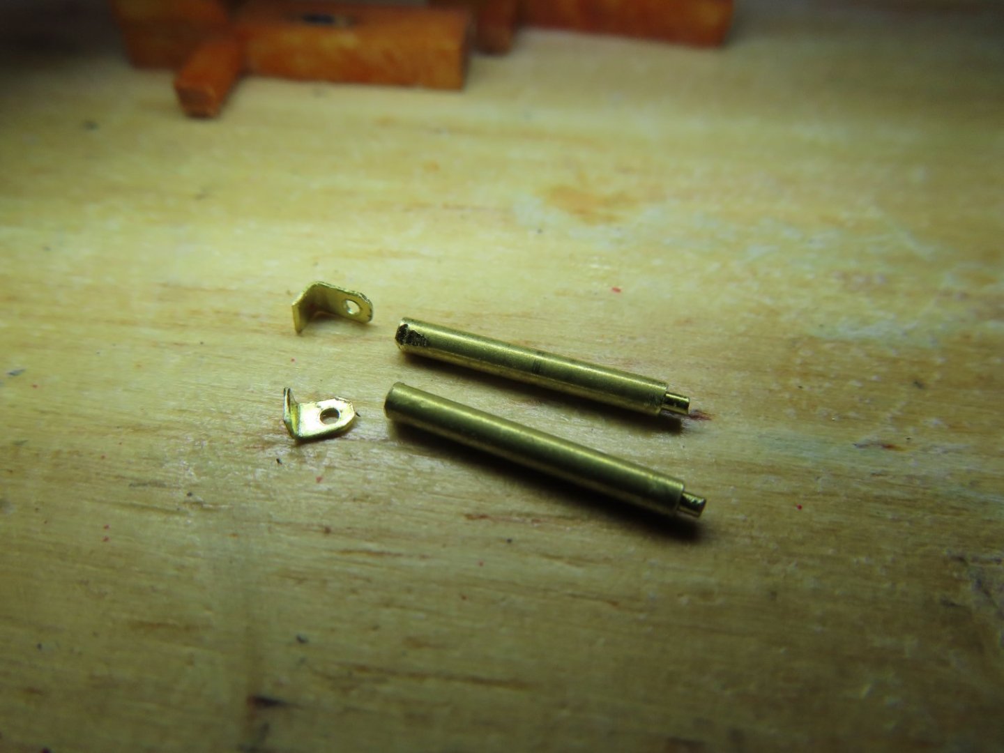
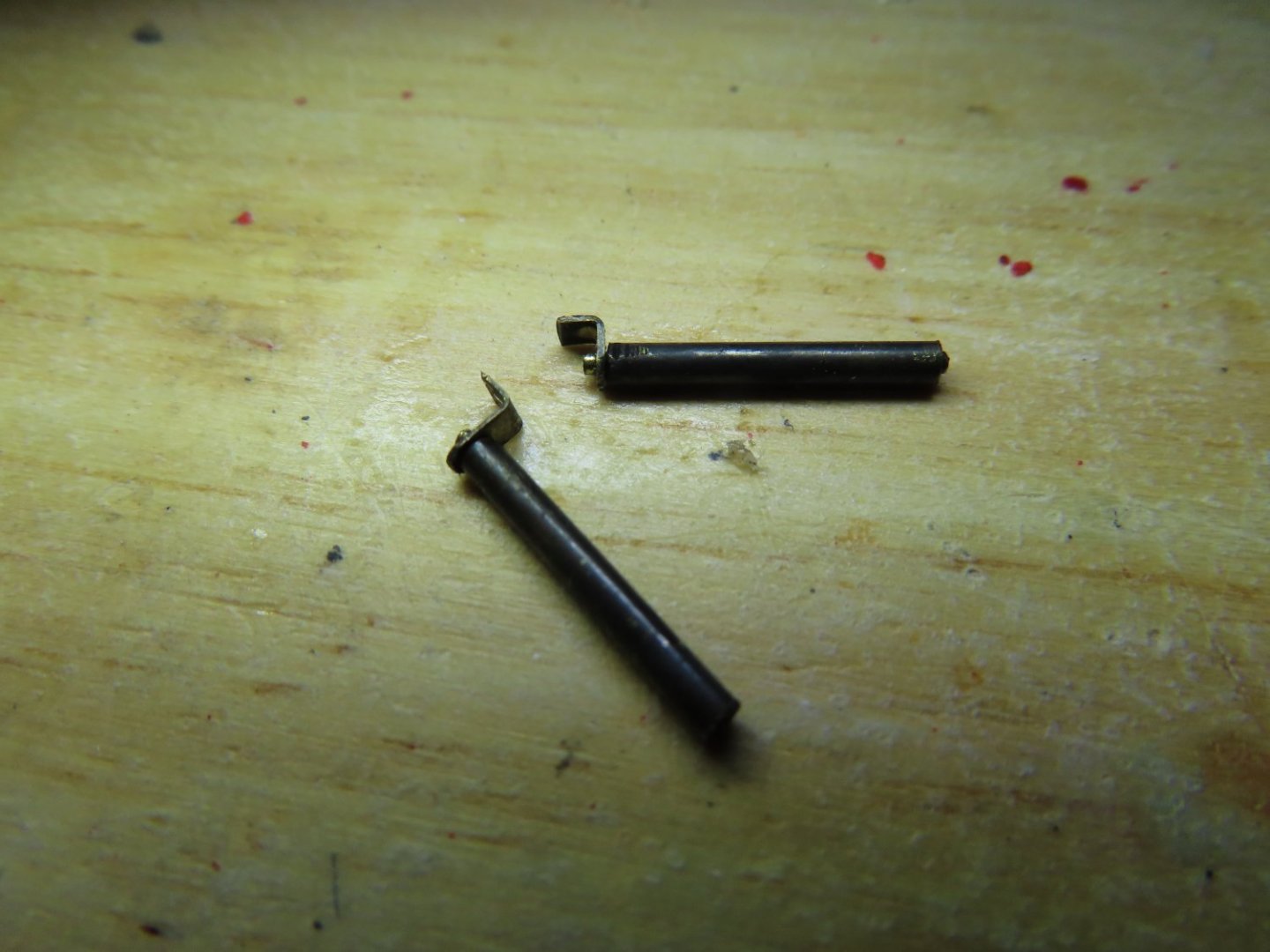
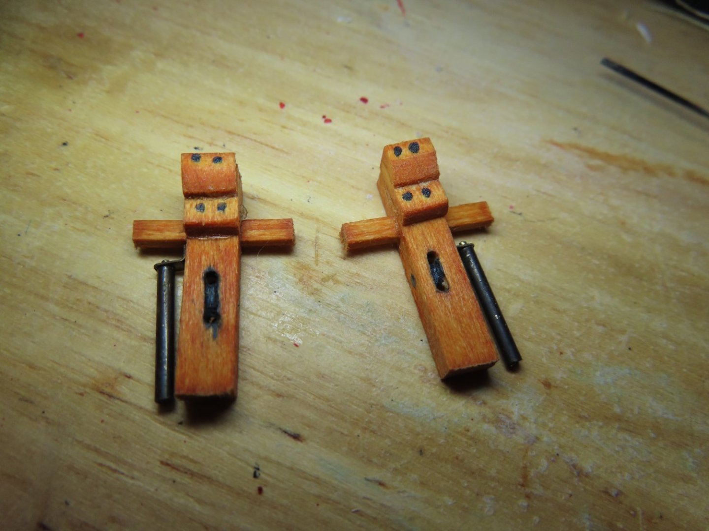
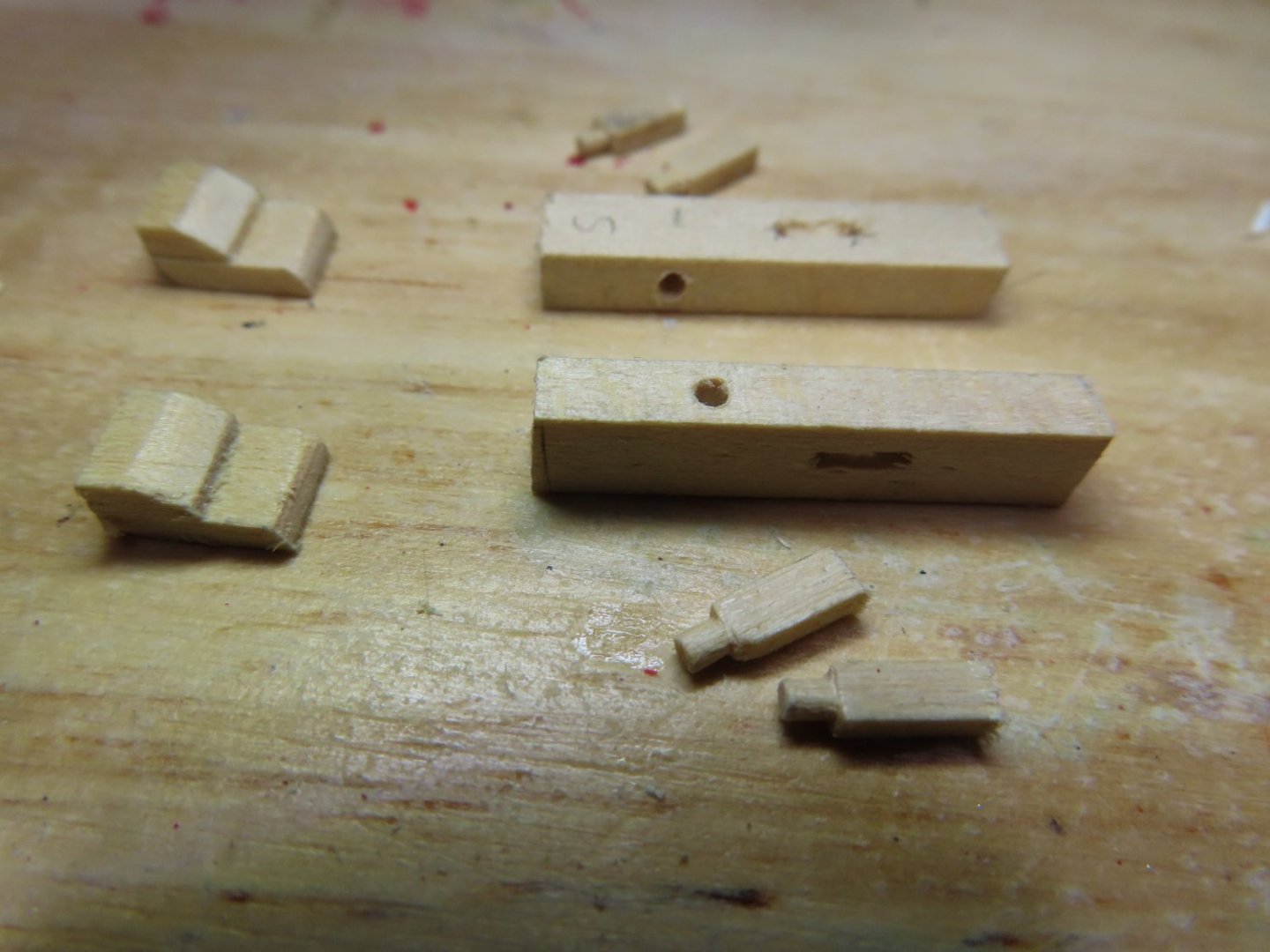
The side attached vertical roller bearings were made from 1/16” brass tube, 1/32” brass rod, and 0.010” brass sheet. After I eyeballed the roller’s length and width, the brass tube was cut to length. The brass rod, which fits inside the tube perfectly, was cut just a bit longer so it protruded. Brackets were fabricated with a hole drilled to accept the rod. In real life, there is a bracket at the bottom as well so the roller bearing can spin, not so for the model. Finally, the brass parts were blackened. and black dots painted as pseudo bolts on the braces.
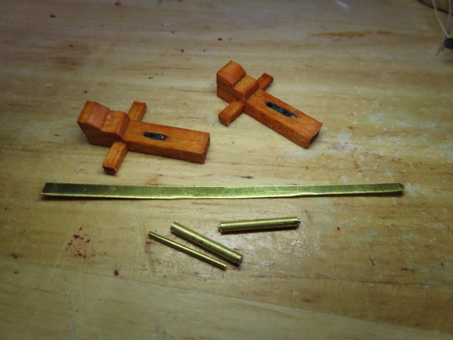


-
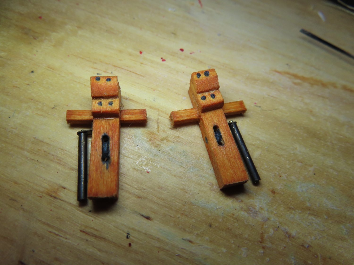
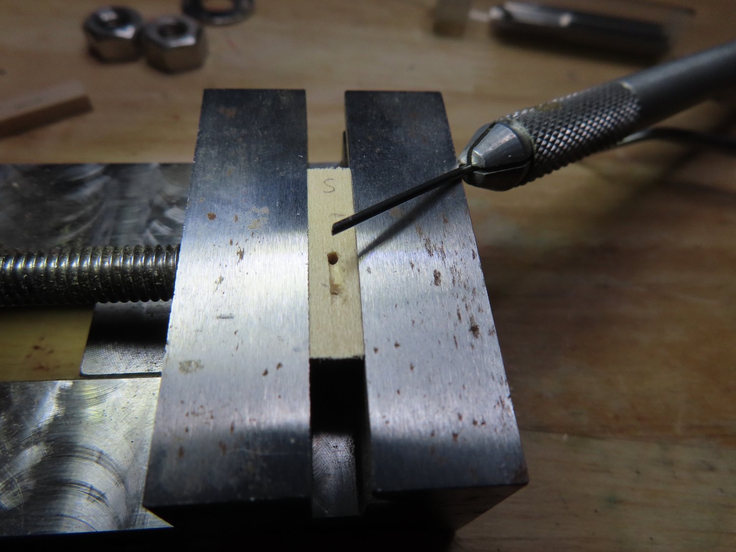
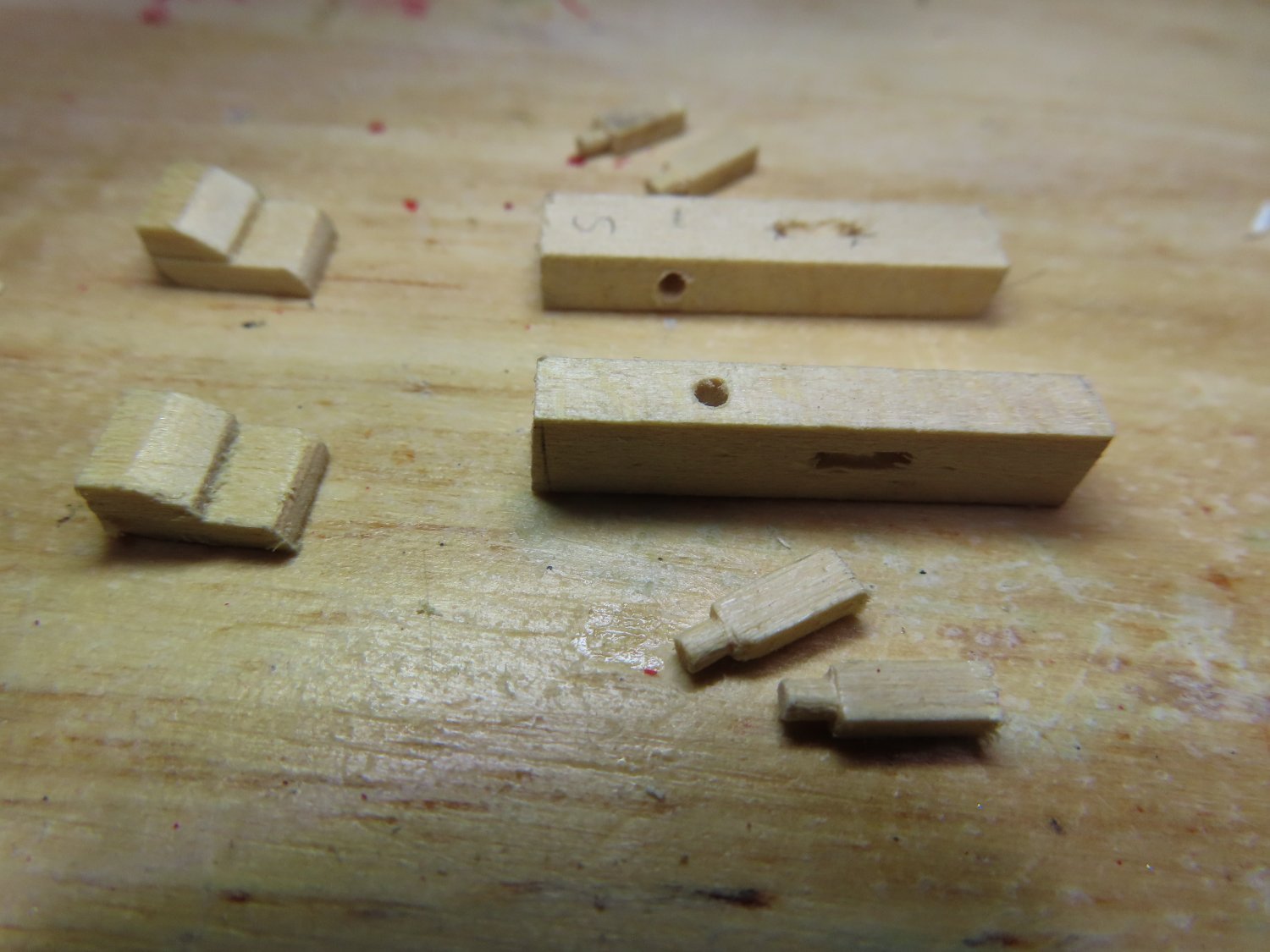
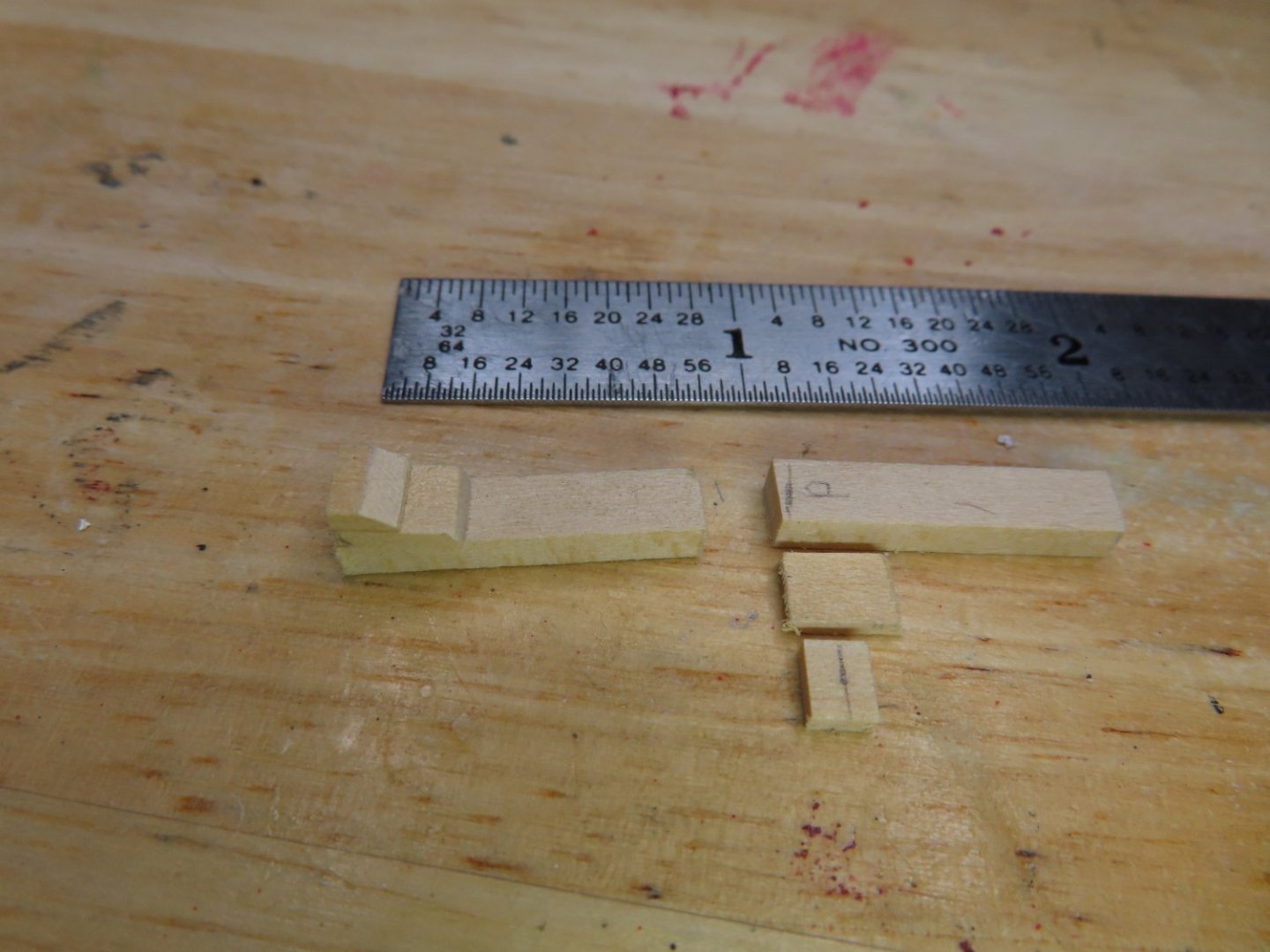
The post sheeves were carved after two holes were drilled into each of the vertical posts. The two brace parts were shaped and glued together before being glued to the posts. The horizontal beam was made in two parts. Instead of trying to insert square cross section beams through square holes cut into the posts which would have been quite difficult, the beams were made as plugs that fit into a drilled round hole which passed through the post. Once assembled, the bitts were stained with Minwax Gunstock 231 and the sheeves painted black.


-
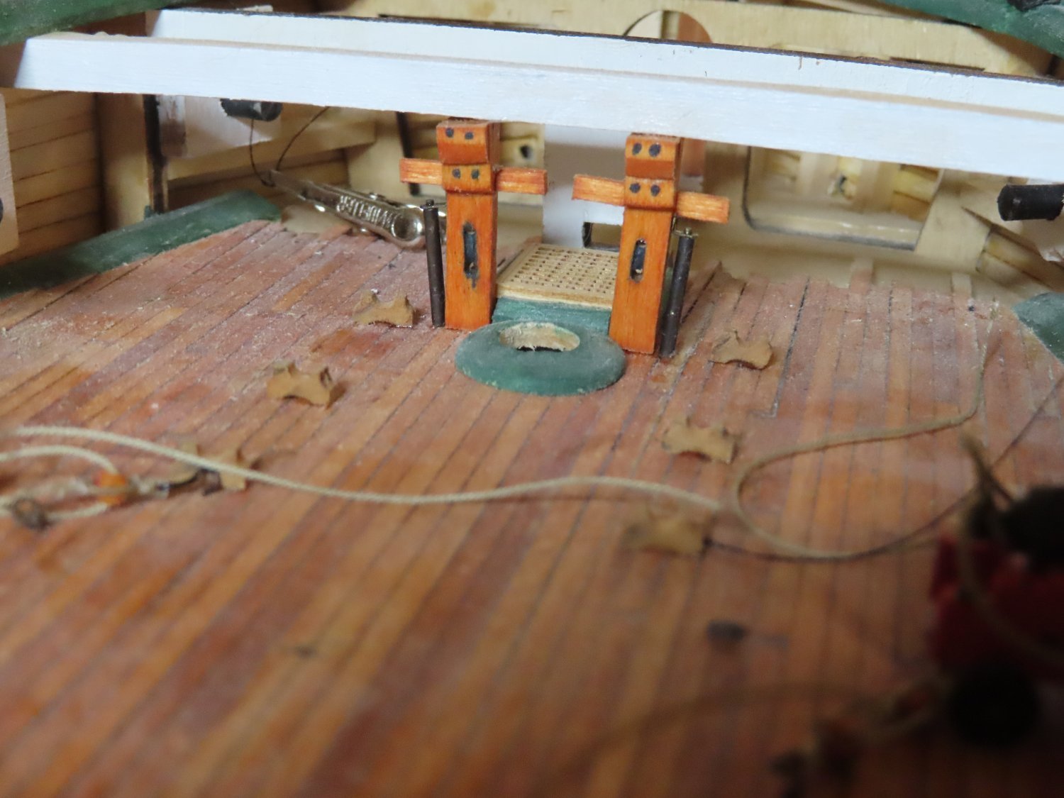
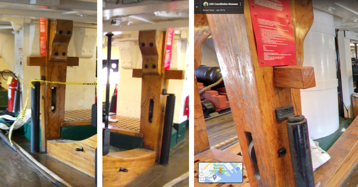
These bitts have a vertical sheave and a horizontal beam which passes through the vertical structural element. Based on the US Navy arrangement drawing, I determined the scale size of the vertical post as 3/16” width x 1/8” depth but did not find any other plans for these bitts. I had to use just my library of images to guesstimate the remainder of the dimensions. The height was easy, the space between the beam and deck. The braces were totally guesstimated. Each bitt was made from three pieces for ease of construction; two for the brace and one for the vertical post.
-
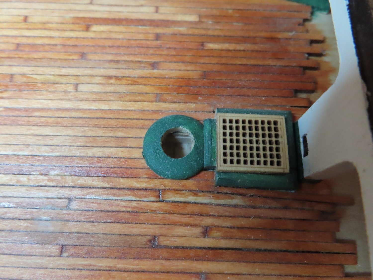
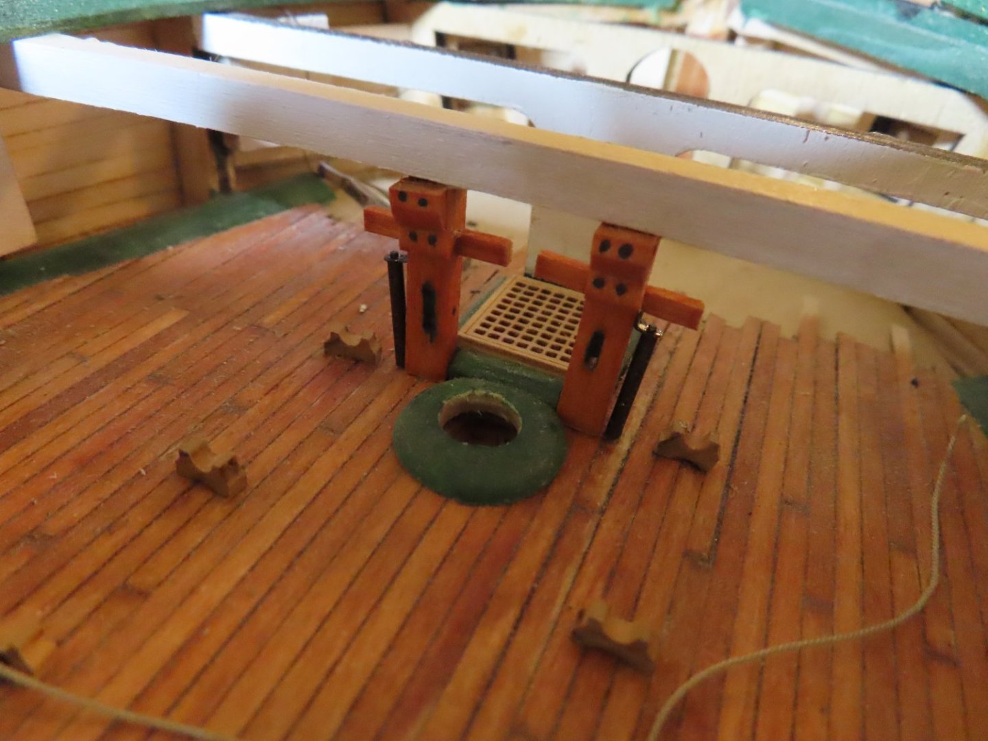
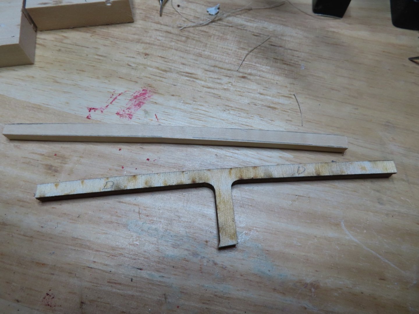
Forward Gun Deck Bitts As I started rigging the third gun and thought, I’m going to go nuts rigging the remaining 20 guns all at once. Not only that, where am I going to store them prior to installation as I will have a bunch of other items (as I’ve mentioned before) that will need to be fabricated and installed as well? So, I decided to put that aside and fabricate the forward gun deck bitts and work my way aft installing all the bits and pieces as I progress one gun port at a time. This way, there will be less loose pieces and it won’t get monotonous. First, I fabricated the ceiling beam between bulkhead C and D. When creating the gun deck so long ago, the spar deck beams, that were previously cut off the hull forming bulkheads, were saved. (These will be used later as the spar deck is fabricated.) Using the bulkhead C beam, a new beam shape between B and C was extrapolated, fabricated, and positioned directly over the aft end of the most forward grating. This grating was previously fabricated with aft notches for the bitts going from the gun deck to the ceiling beam.

-
USS Constitution by mtbediz - 1:76
JSGerson replied to mtbediz's topic in - Build logs for subjects built 1751 - 1800
I can appreciate the effort that went into creating the pintles and gudgeons. My method was slightly different then yours, but getting all those pieces aligned properly was tough. You did a nice clean job. Well done, Jon -
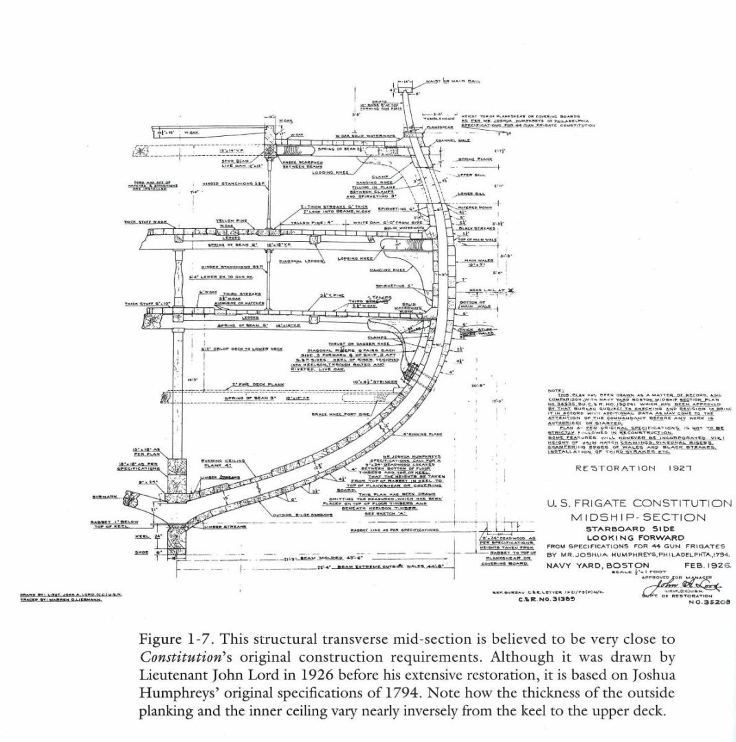
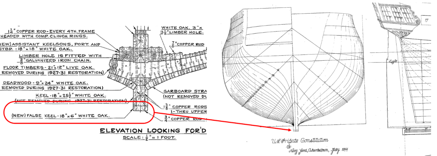
A ship has a keel is its structural backbone. A false keel is that piece of wood that actually sits under the keel to protect it and the heads of the bolts holding the main keel together. If a ship hits rocks or a reef or the damage from sea worms, the false keel takes the brunt of the abuse. It can be replaced so no harm comes to the main keel. For the USS Constitution, I have not seen model maker attach a false keel to their model, probably because it is only 6” thick full scale. At 1/96 scale that would be 0.0625” or 1/16” thick on your model and would be covered with copper plate. Jon
-
I got my Byrnes saw about ten years ago, and it still works as well now as the day I got it. However, getting a new Byrnes saw may be more difficult. It was just recently announced that Jim Byrnes, that wonderful man who made the saws, died a few weeks ago. Whether the shop will make more is not known. The shop has reopened, but at present, they they are only selling what's in stock. He will be missed. Jon
-
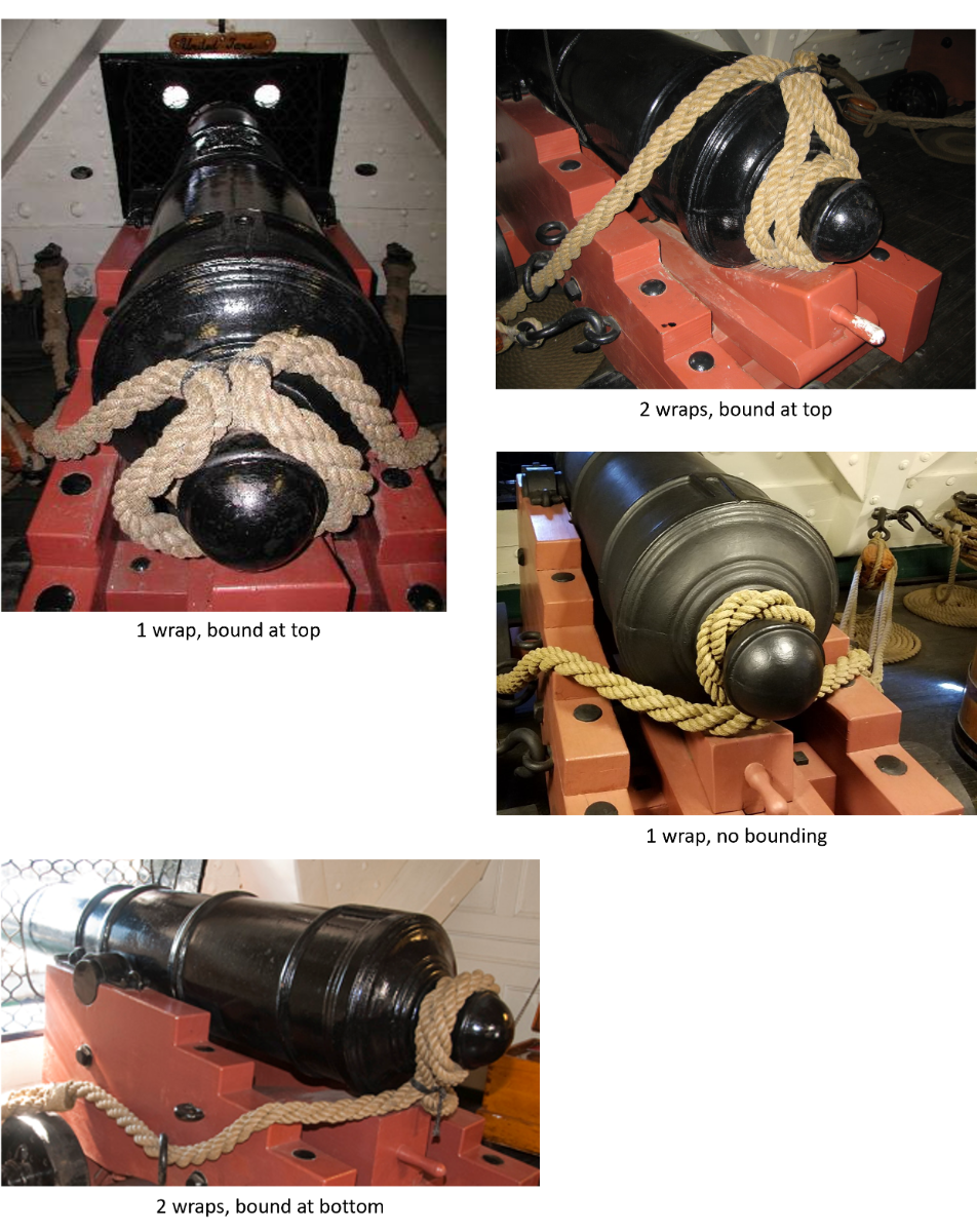
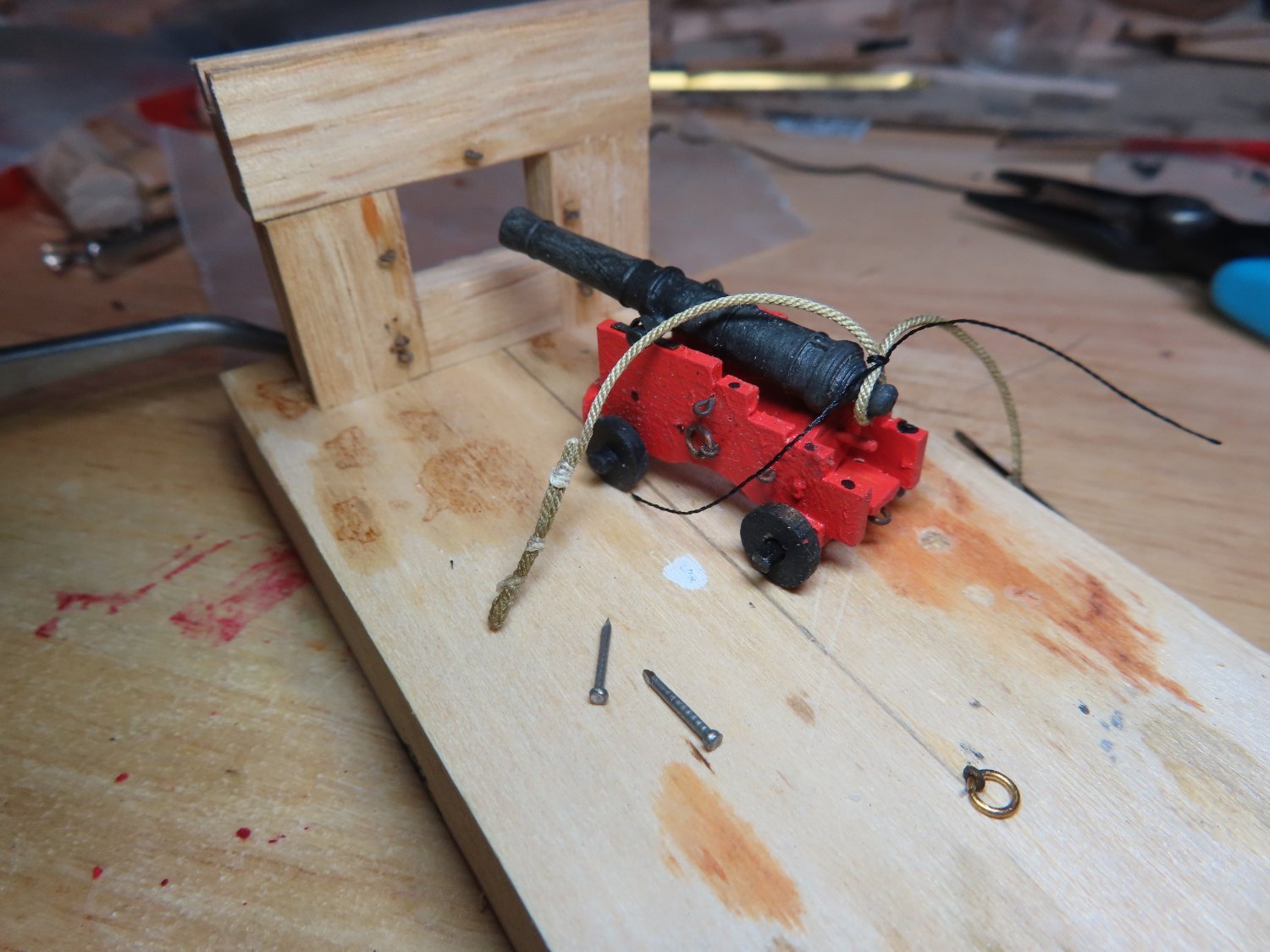
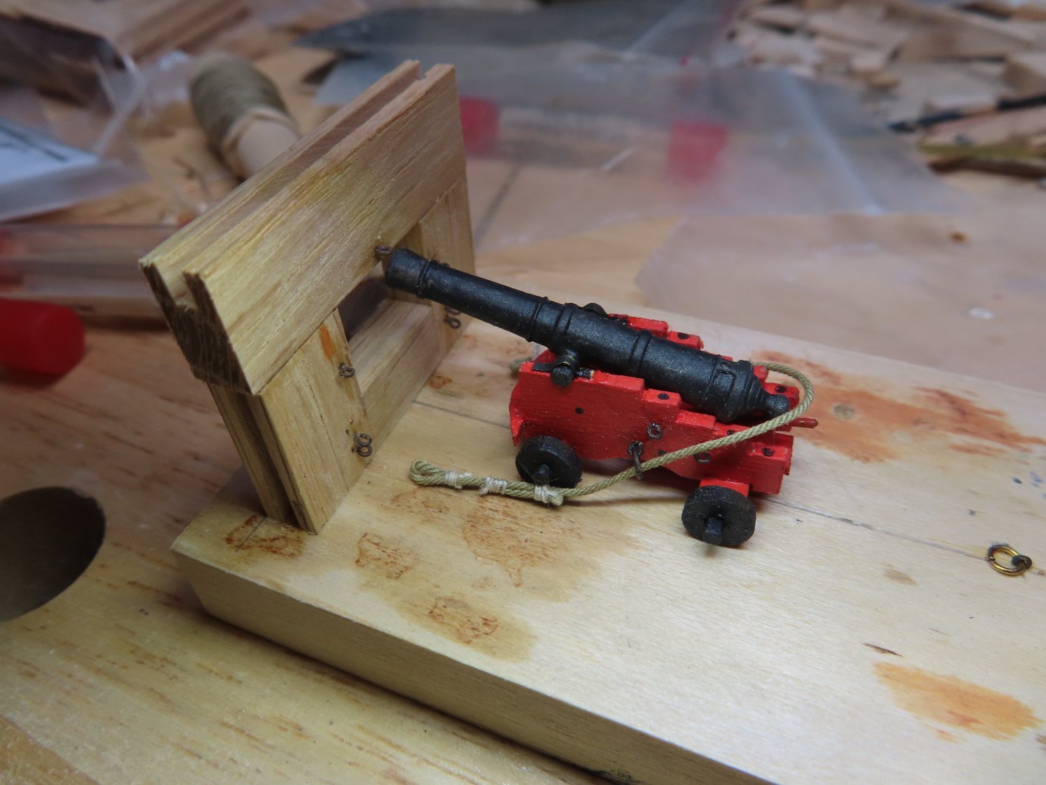
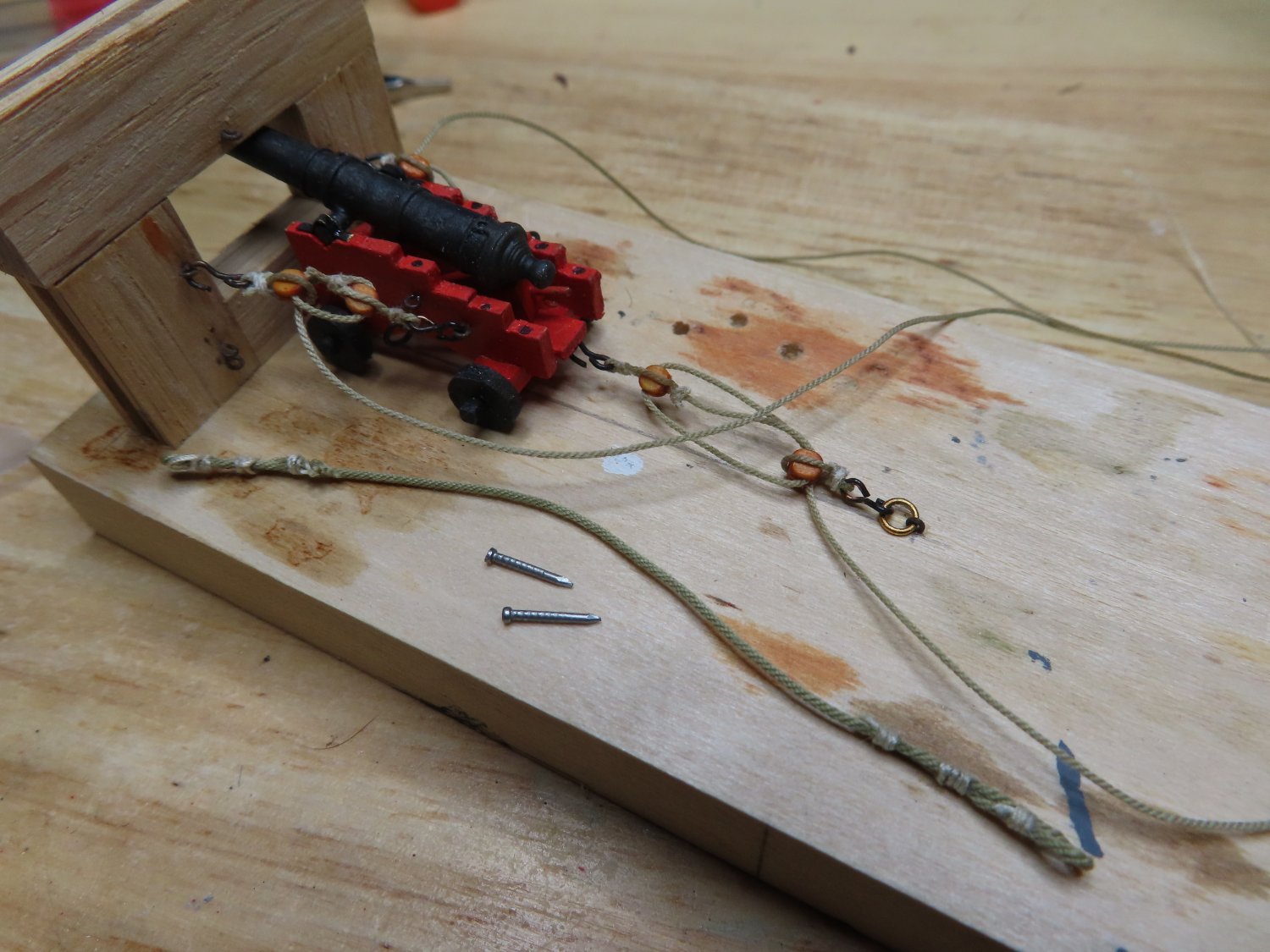
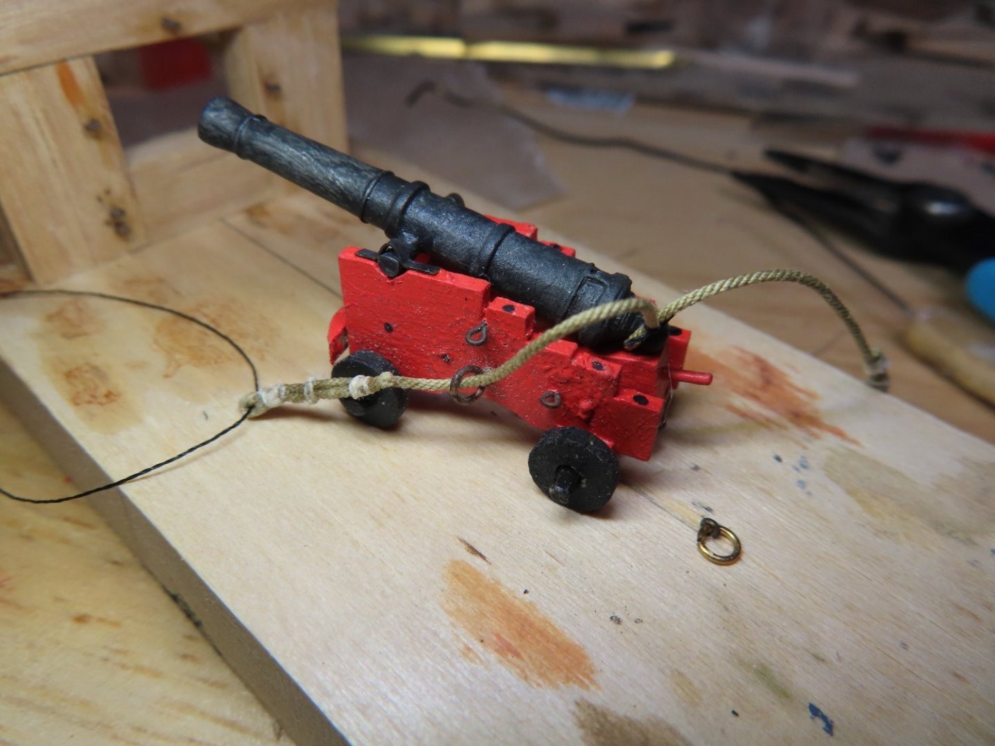
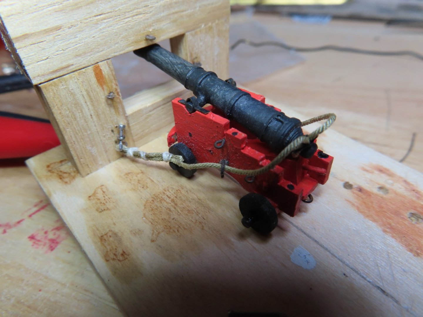
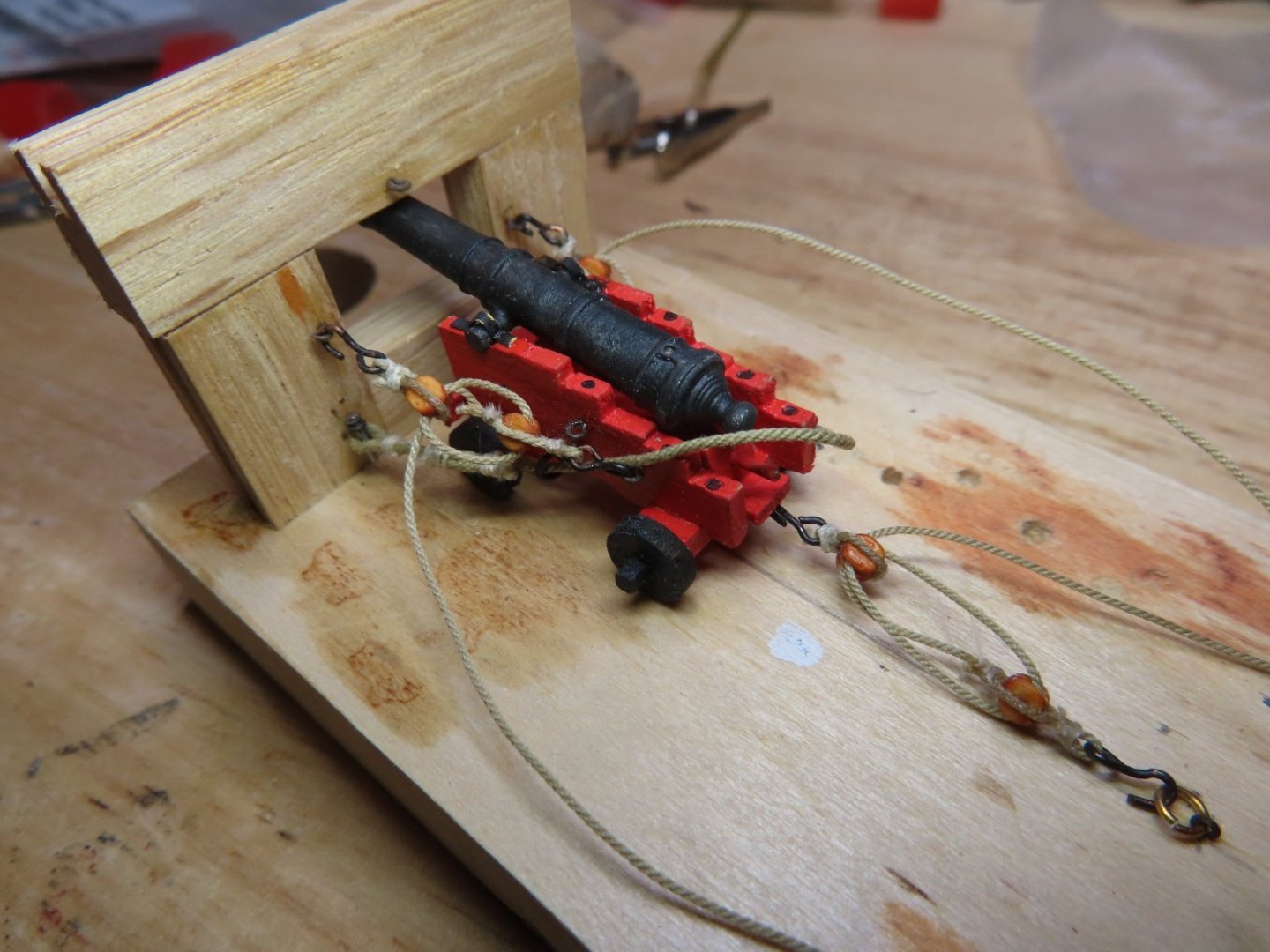
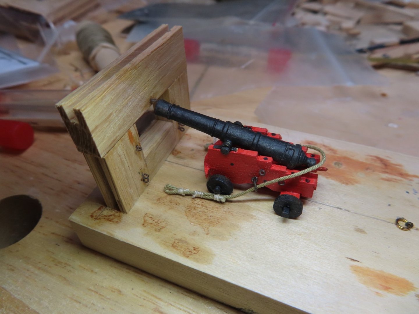
The recoil rope is wrapped around the spherical nob or button at the back of the gun, but there does not seem to be a consistent method used on the Constitution (see first image below). Once more I removed all the tackle because I should have done this before I threaded the rope through to gun’s rings. I chose the simplest method to attach the recoil rope on the gun button as seen below. This assures I could make each side of the rope equal length., Once more, the rope was threaded through the vertical ring and pinned to the bulwark. With the recoil rope now installed properly, the remainder of the tackle re-hooked once again. The gun jig proved its worth. I would have hated to have learned the sequence while trying to do this on the model. Now I’ve got two guns rigged and sitting on the model. The rope positions are not finalized nor is anything glued into their final position. I want these loose until I build the beams supporting the spar deck with its stations, not to mention the furniture I’ve already fabricated. There are a lot of moving parts that must fit, and I want the flexibility to adjust them if needed. Only 20 more to rig.


-
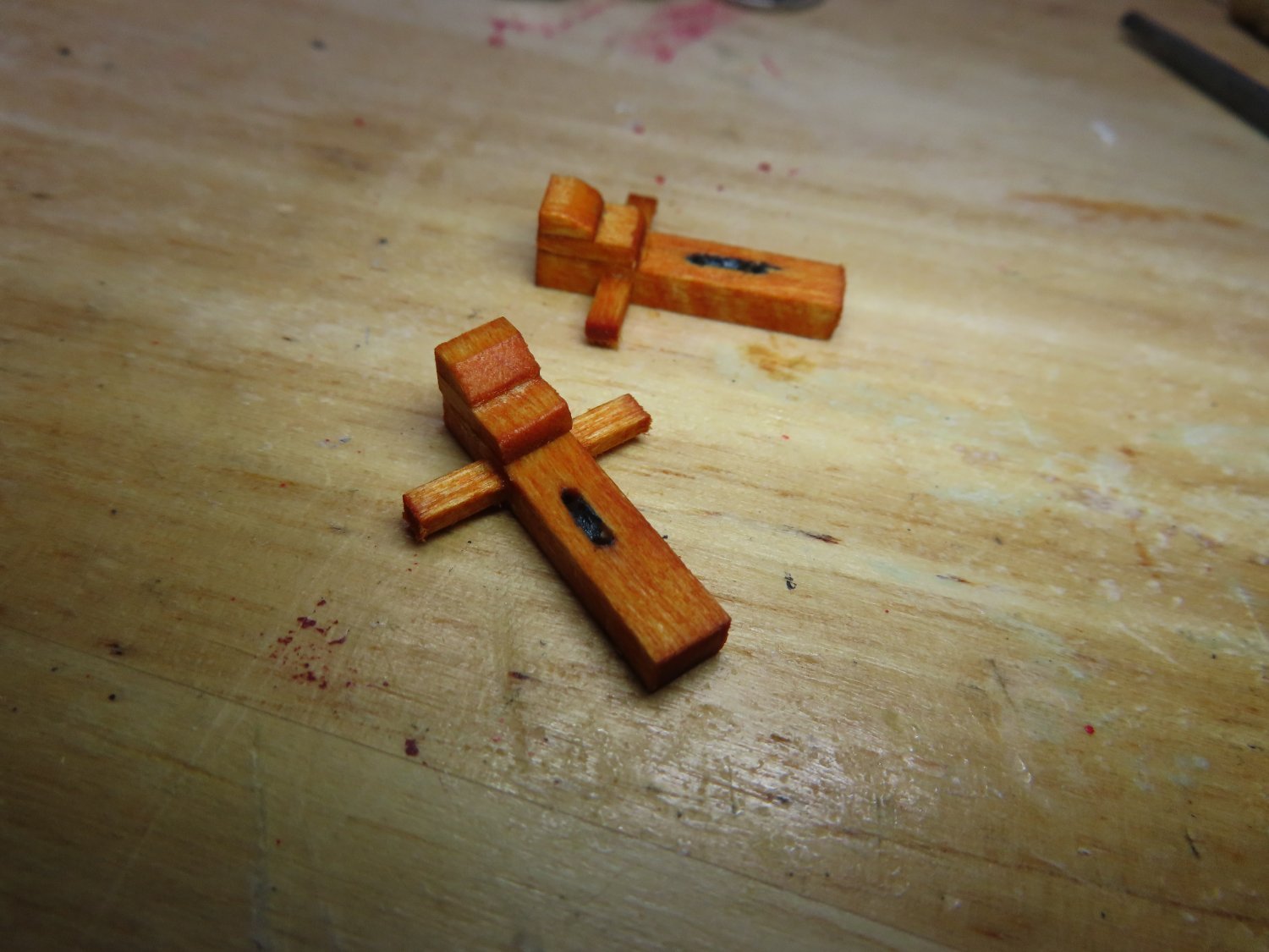
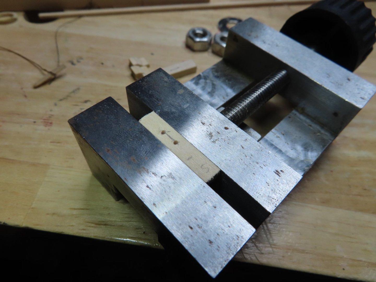
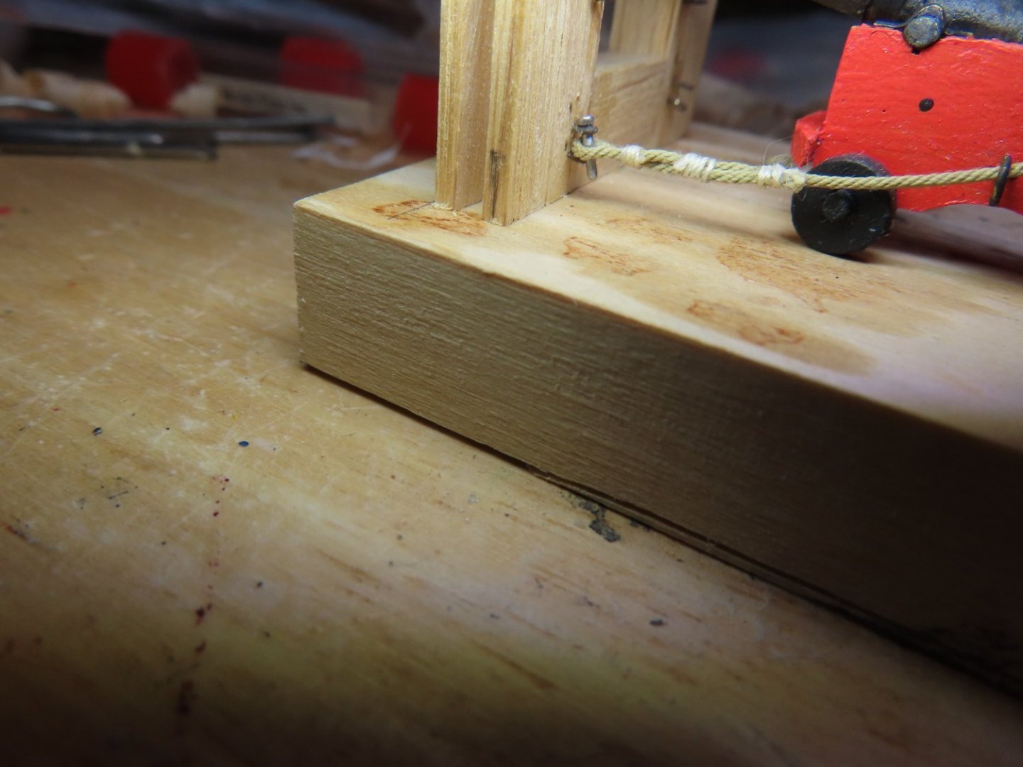
The triple seized looped ends of the recoil rope were attached to bulwark with pins that drop through two eyebolts attached to the bulwarks with the rope loop in between. The pins were created by shortening nails (typically used for nailing planking to bulkheads, seen in the above image). Nails were used because of their nail heads. A piece of rod would just fall through the eyebolts. Those nails had to be filed just a bit narrower for them to fit through the bulwark’s eyebolts. All of this work was done on the protype in the jig.
-
All the tackle was removed because I found it much easier to thread the recoil rope first when I could hold on to the flopping vertical ring for threading the recoil rope. After a little trial and error, I passed a piece of thread through the ring then through the rope end loop and back through the ring again. After a little coaxing, I was able to pull the loop through the ring with the thread. Rope just does not want to be pushed. Then the tackle lines were rebooked on.
-
When I tried to thread the recoil rope through the vertical rings on the carriage, it wasn’t as easy as it seemed. The triple seized looped ends of the rope didn’t fit through the vertical ring. Note, in the image below, the initial recoil rope was made too long and was subsequently trimmed down.