JSGerson
-
Posts
2,633 -
Joined
-
Last visited
Content Type
Profiles
Forums
Gallery
Events
Everything posted by JSGerson
-

USS Constitution by mtbediz - 1:76
JSGerson replied to mtbediz's topic in - Build logs for subjects built 1751 - 1800
She was deployed October 21 1797. -
USS Constitution by mtbediz - 1:76
JSGerson replied to mtbediz's topic in - Build logs for subjects built 1751 - 1800
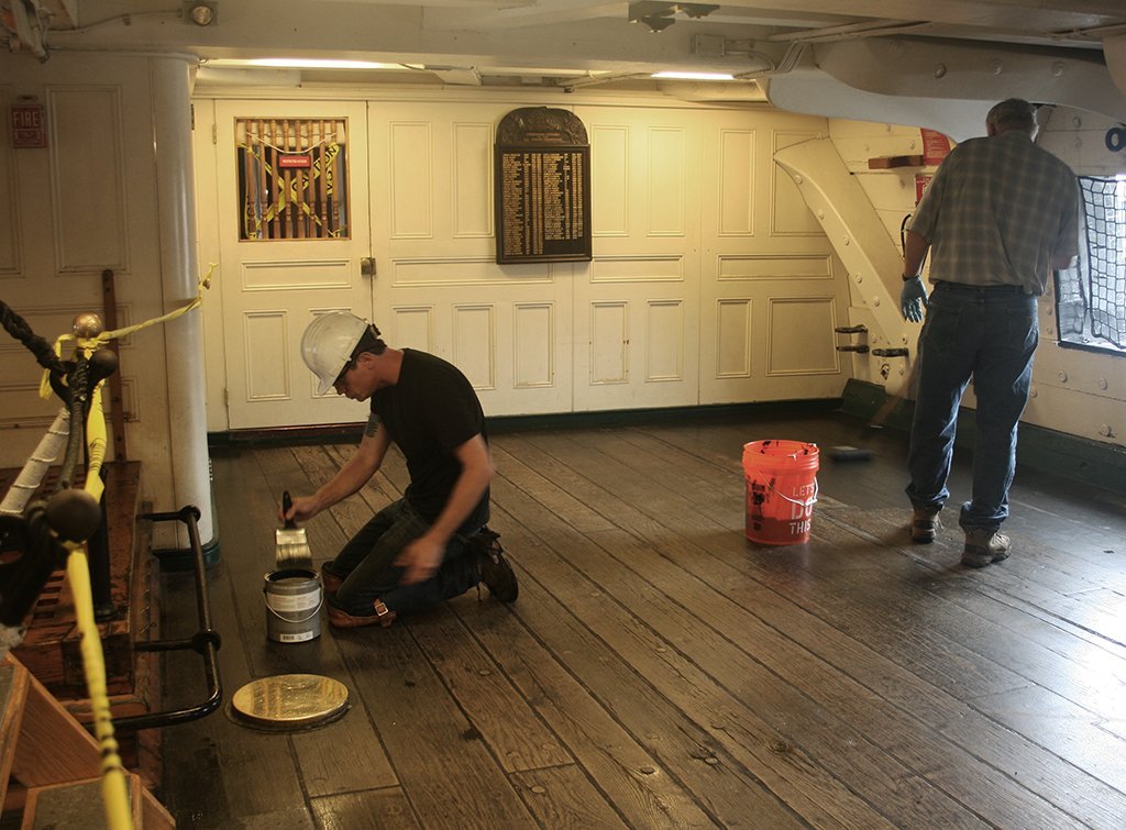
I'm not surprised those auxiliary beams inside the ship obscure the gun deck view. This war ship, although made of wood (obviously), was built to take punishment. If you look at the photo below from the 1873-77 restoration, you can't even see inside the ship with her hull planking removed. The hull frames were so close to each other, the ship looks solid. To take a phrase from an old Timex watch advertising slogan, "it takes a 'licken' and keeps on 'ticken,'" No wonder they called her "Old Ironsides." Jon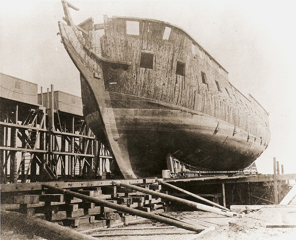
-
USS Constitution by mtbediz - 1:76
JSGerson replied to mtbediz's topic in - Build logs for subjects built 1751 - 1800
Glad you came to that conclusion although I love your beautiful workmanship on those beams. Jon -
Magnets or no magnets, your planking looks great! Jon
-
USS Constitution by mtbediz - 1:76
JSGerson replied to mtbediz's topic in - Build logs for subjects built 1751 - 1800
Looks like the real ship. Nice work! Jon -
USS Constitution by mtbediz - 1:76
JSGerson replied to mtbediz's topic in - Build logs for subjects built 1751 - 1800
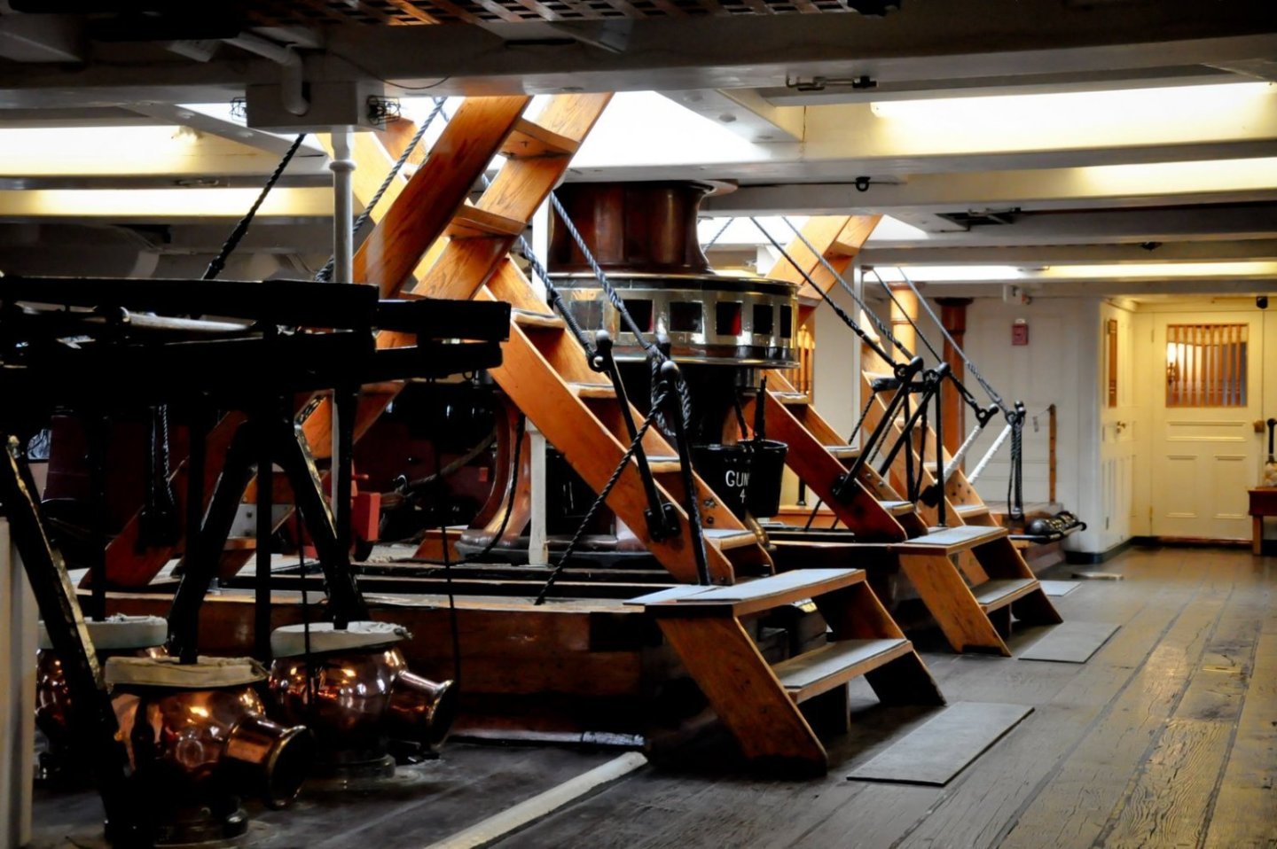
I initially added the hand ropes on the ladders going from the gun deck to the pseudo berth deck, or at least I tried. Over time they have all been knocked off due to the weak bond of the very limited gluing area surfaces. Because of the limited viewing and now inaccessible areas at the bottom of those ladders, I won't be replacing the hand ropes. I'll probably try again for the ladders going to the spar deck, We'll see what happens. Jon -
USS Constitution by mtbediz - 1:76
JSGerson replied to mtbediz's topic in - Build logs for subjects built 1751 - 1800
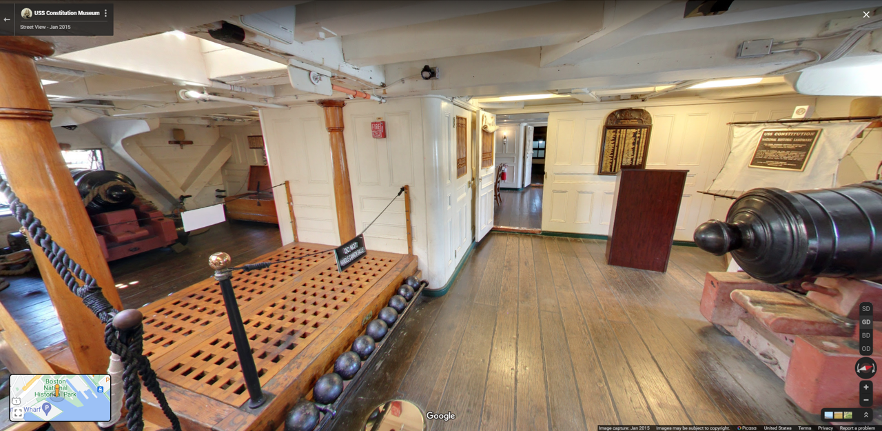
Now the question is, are the hand ropes for the tourists or were they part of the ladder the crew would have used in 1812? For example, the netting around the gun deck gun ports is to prevent idiot tourists from falling out of the ship. It is something I won't add to my model. Jon -
USS Constitution by mtbediz - 1:76
JSGerson replied to mtbediz's topic in - Build logs for subjects built 1751 - 1800
GGibson, well, let's see what I can do for you. Jon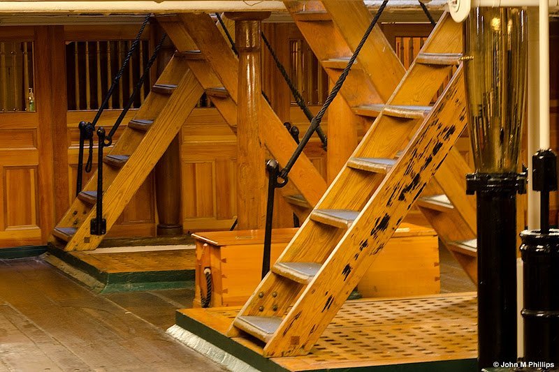

-
USS Constitution by mtbediz - 1:76
JSGerson replied to mtbediz's topic in - Build logs for subjects built 1751 - 1800
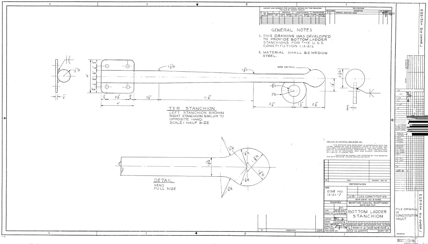
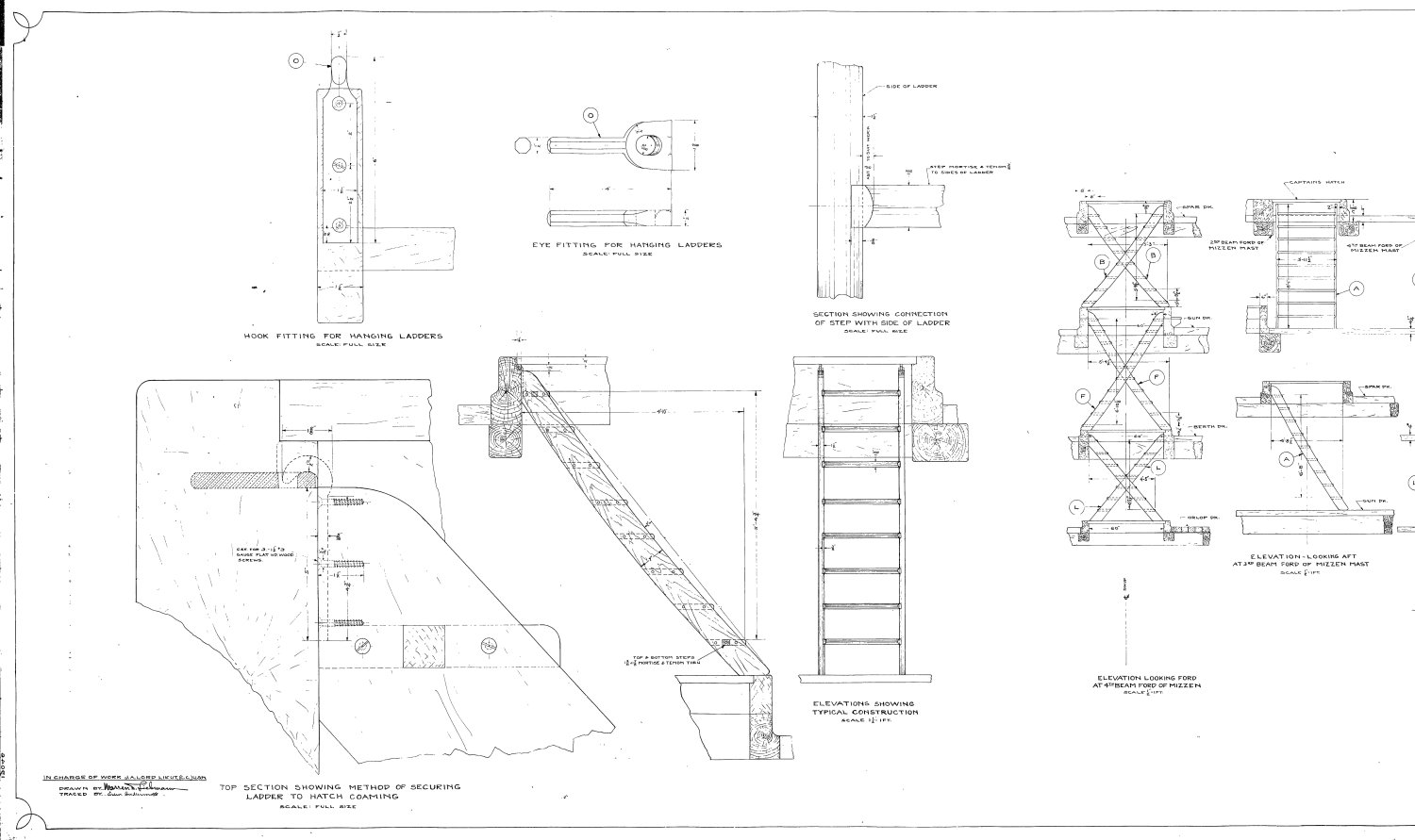
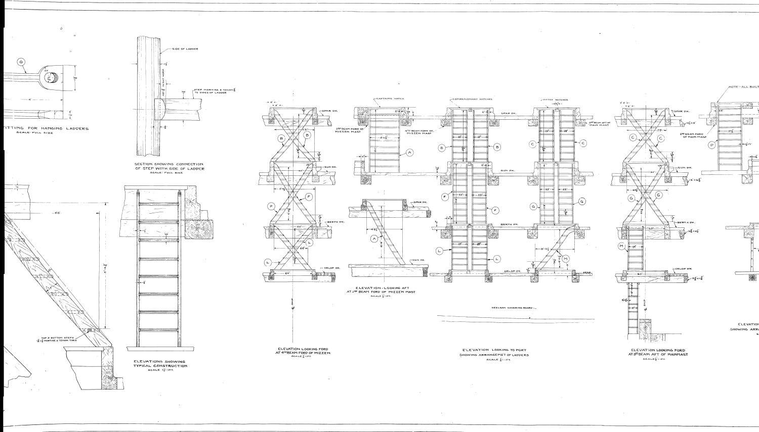
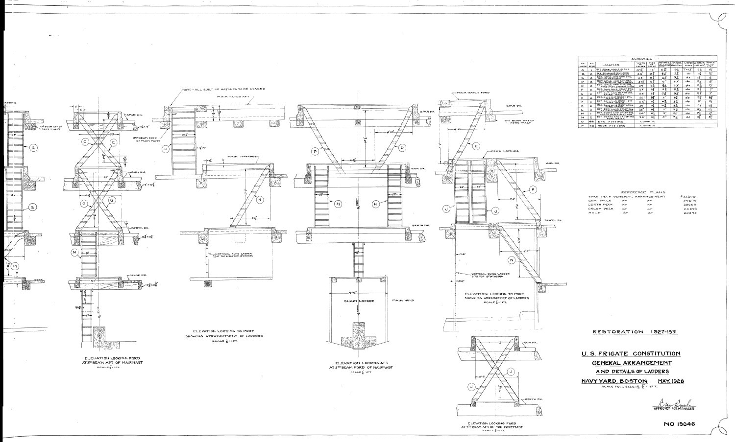
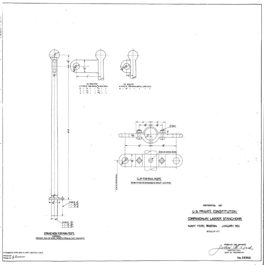
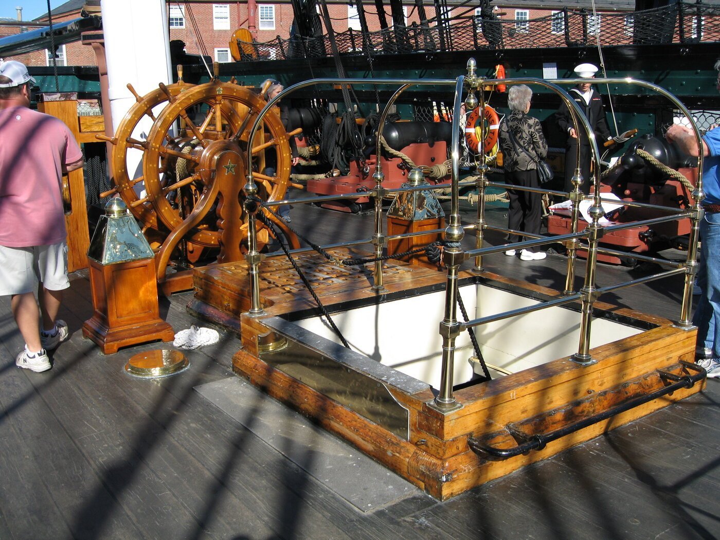
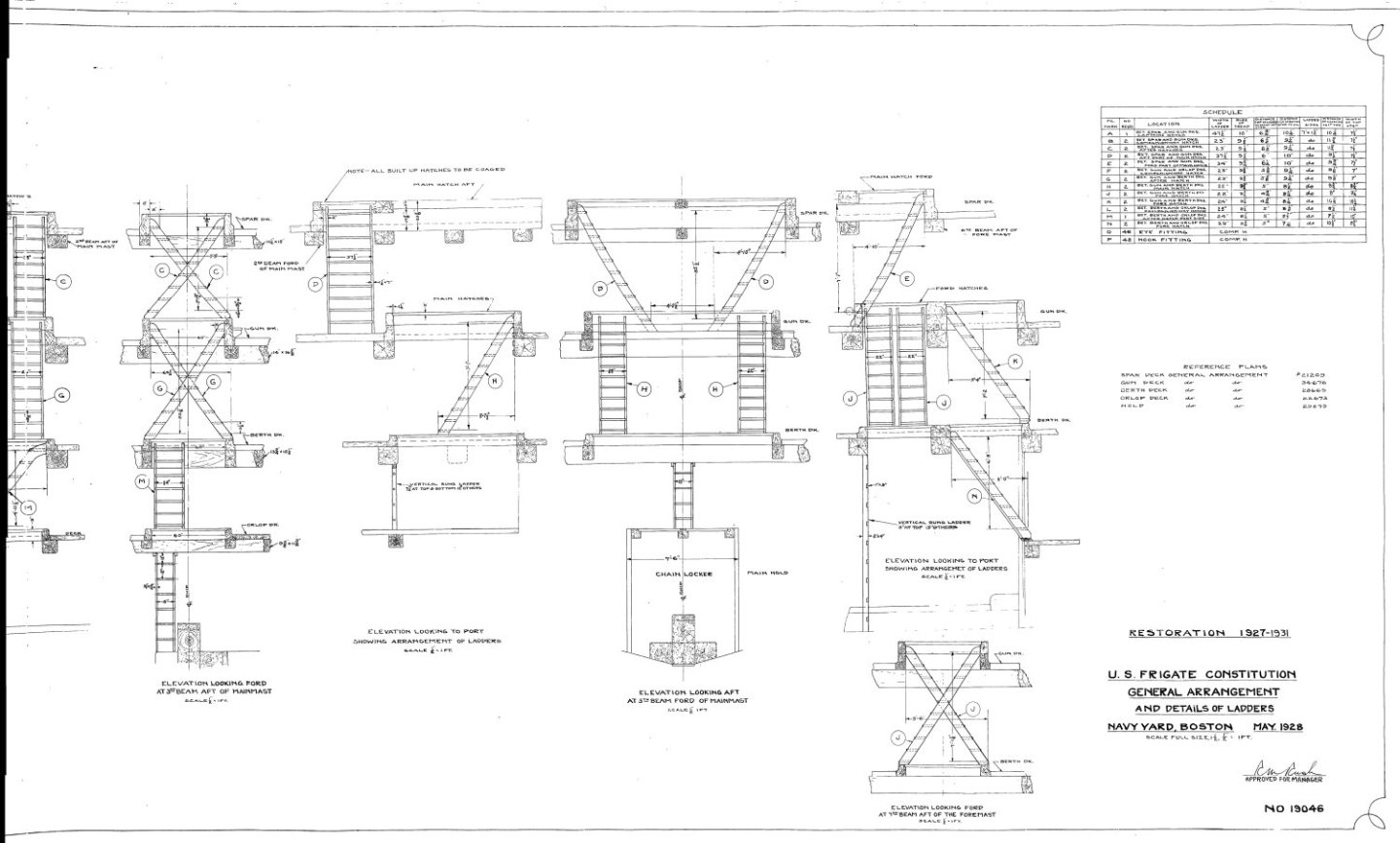
After studying your beautiful ladders, I think I may have discovered an unfortunate measuring error. Per the attached US Navy plans, the ladders extend into the grating which extends above the deck. Your ladders stop at the top of the floor beams. See attached plans. I really hate to mess up your fine wood work.🫤 Jon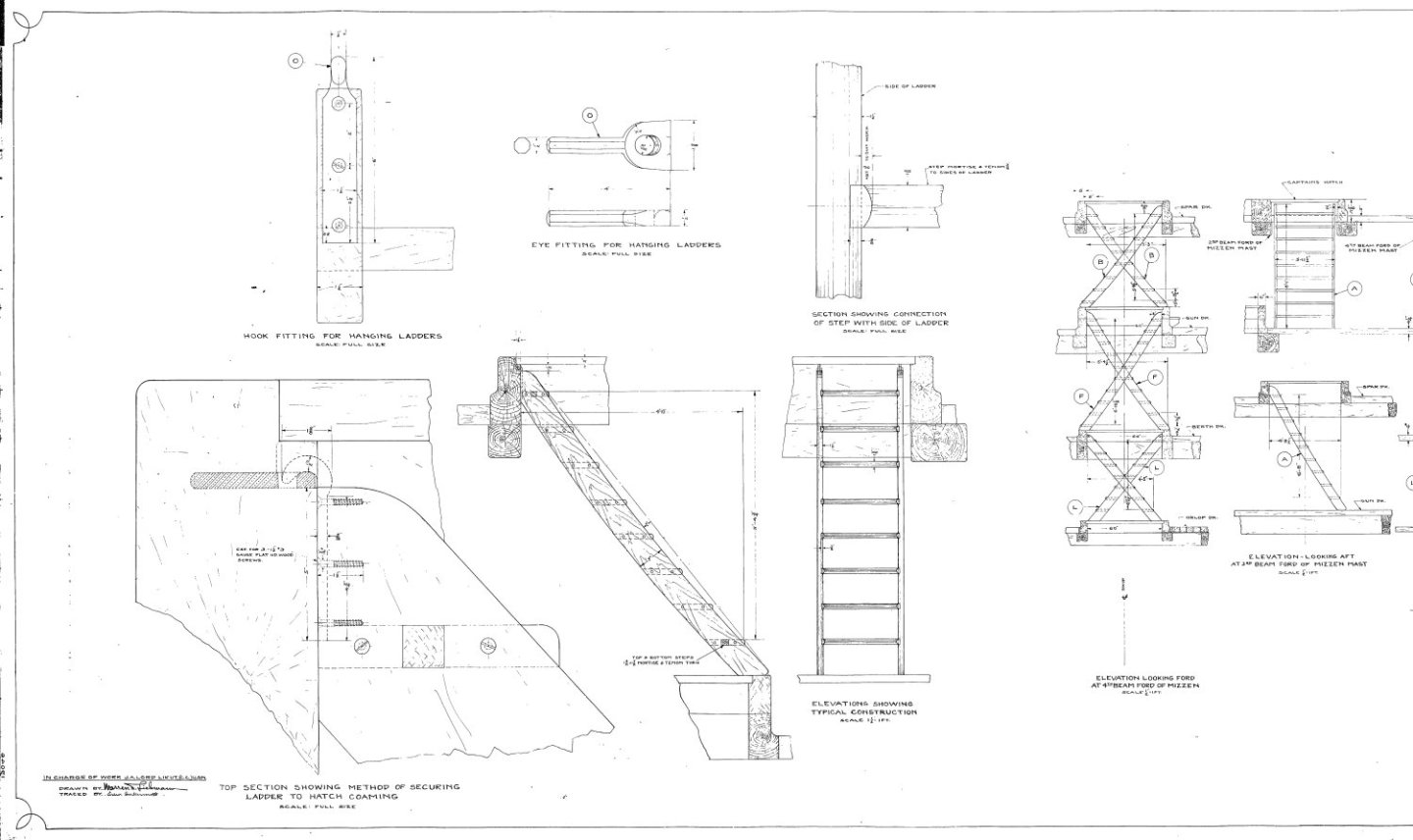

-
USS Constitution by mtbediz - 1:76
JSGerson replied to mtbediz's topic in - Build logs for subjects built 1751 - 1800
Very nice ladders. They have been one of the banes of my modeling experience. I've tried different methods, tools, and jigs and have been not been happy with any of my results. I'll have to give your obvious successful method a try when the time comes. Jon -
USS Constitution by mtbediz - 1:76
JSGerson replied to mtbediz's topic in - Build logs for subjects built 1751 - 1800
That chain worked out very nice for you. Jon -
Thanks all for the kudos!🤗 Greg, I got that clamp from Micro Mark. I've had for a number of years, but rarely had a chance to use it. I'll probably use it again once I get to fabricating the various ship's hold framings on the spar deck.
-
Mustafa. I think we are a mutual admiration society😁
-
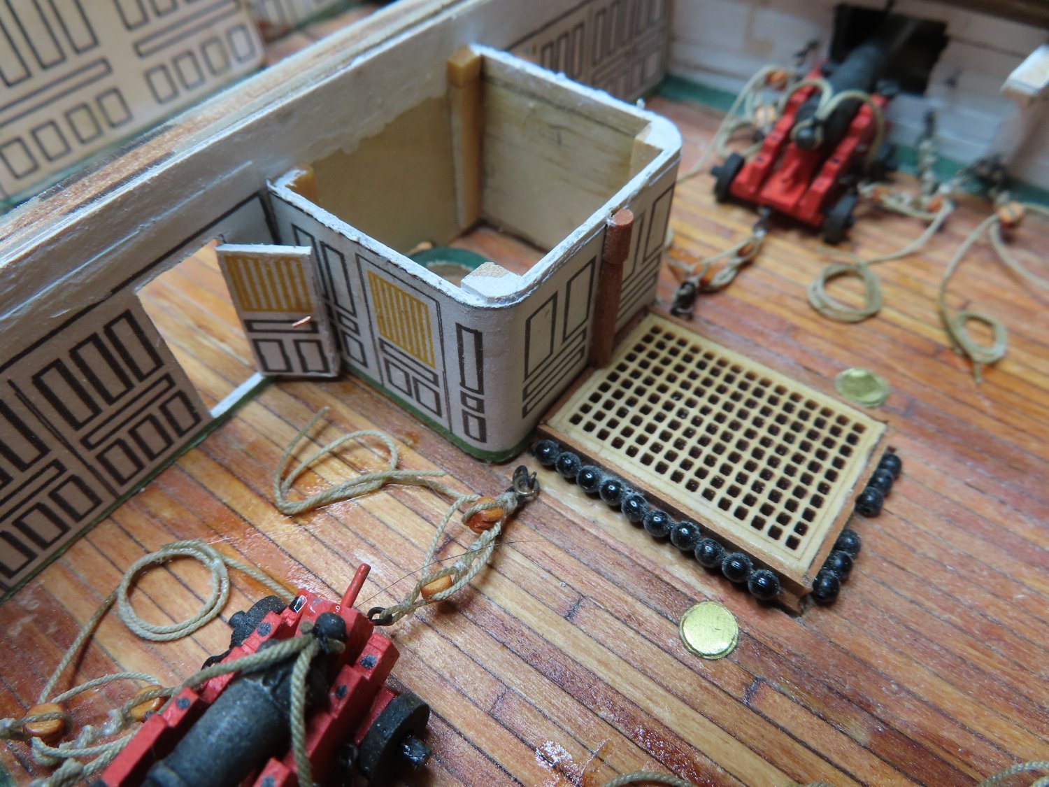
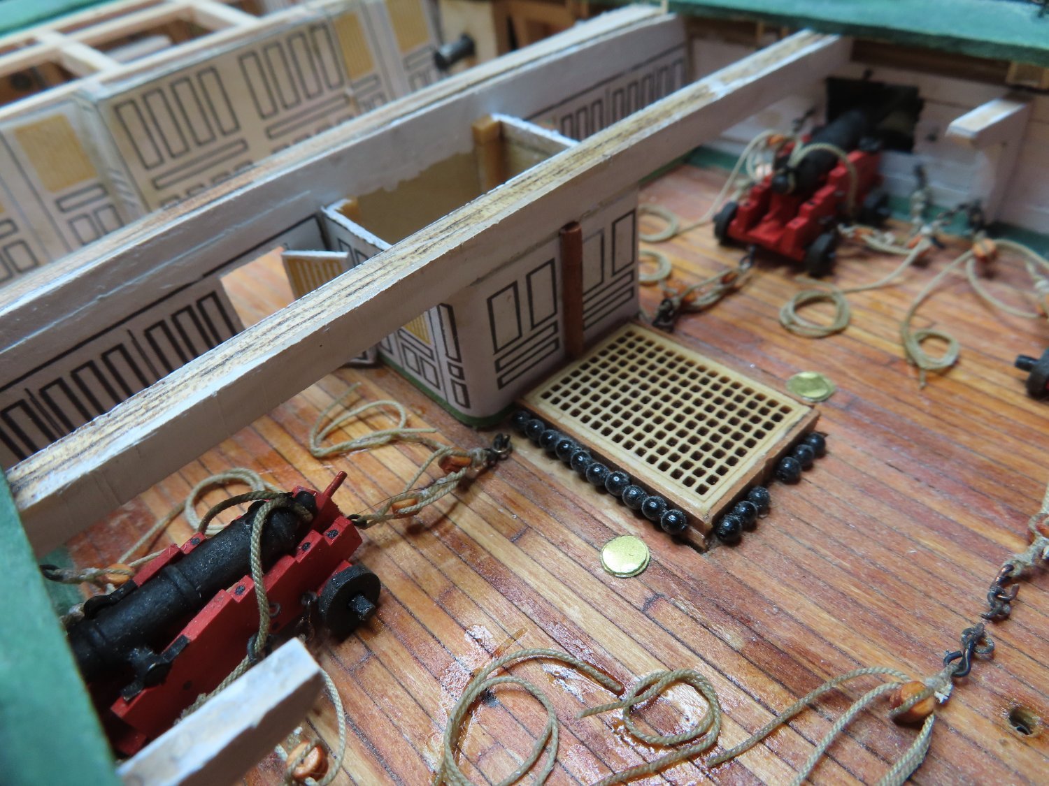
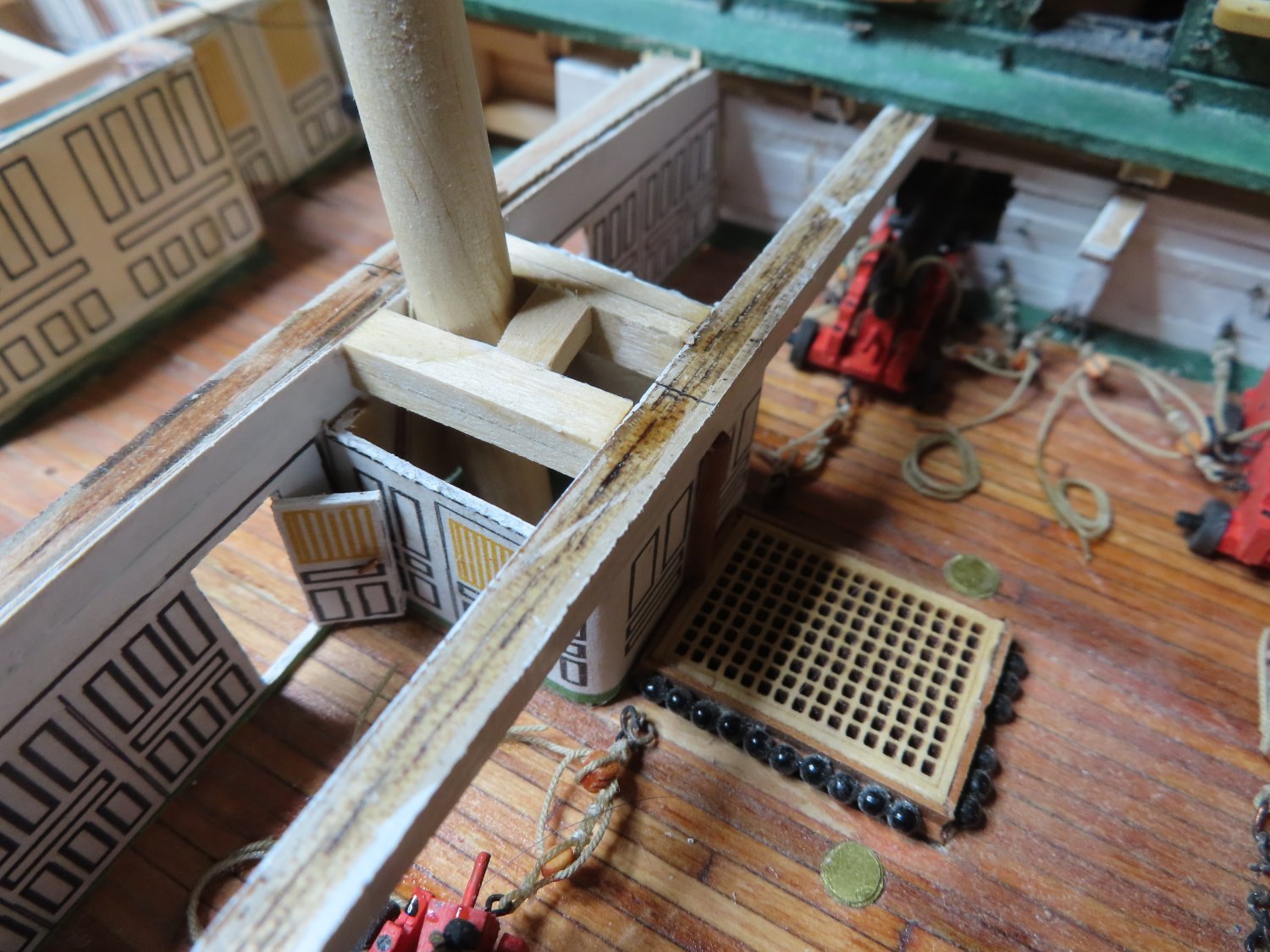
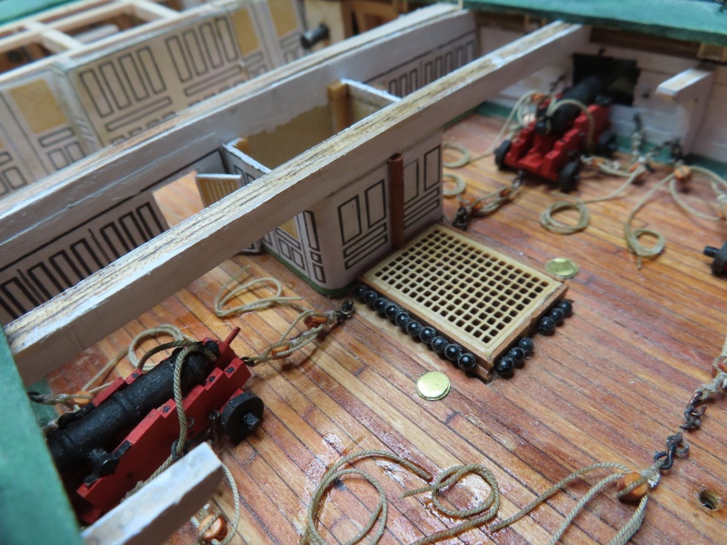
While all of this was going on, I was also busy rigging four more sets of guns to match pace with the gun deck construction. These had to be in position before I could glue into place the dining partition, the Commodore’s pantry, and the spar deck floor beams. The partition doors were then installed in an open configuration leading into the dining area. The last item was installing the mizzen mast supports giving the future mast a 5° rake.


-
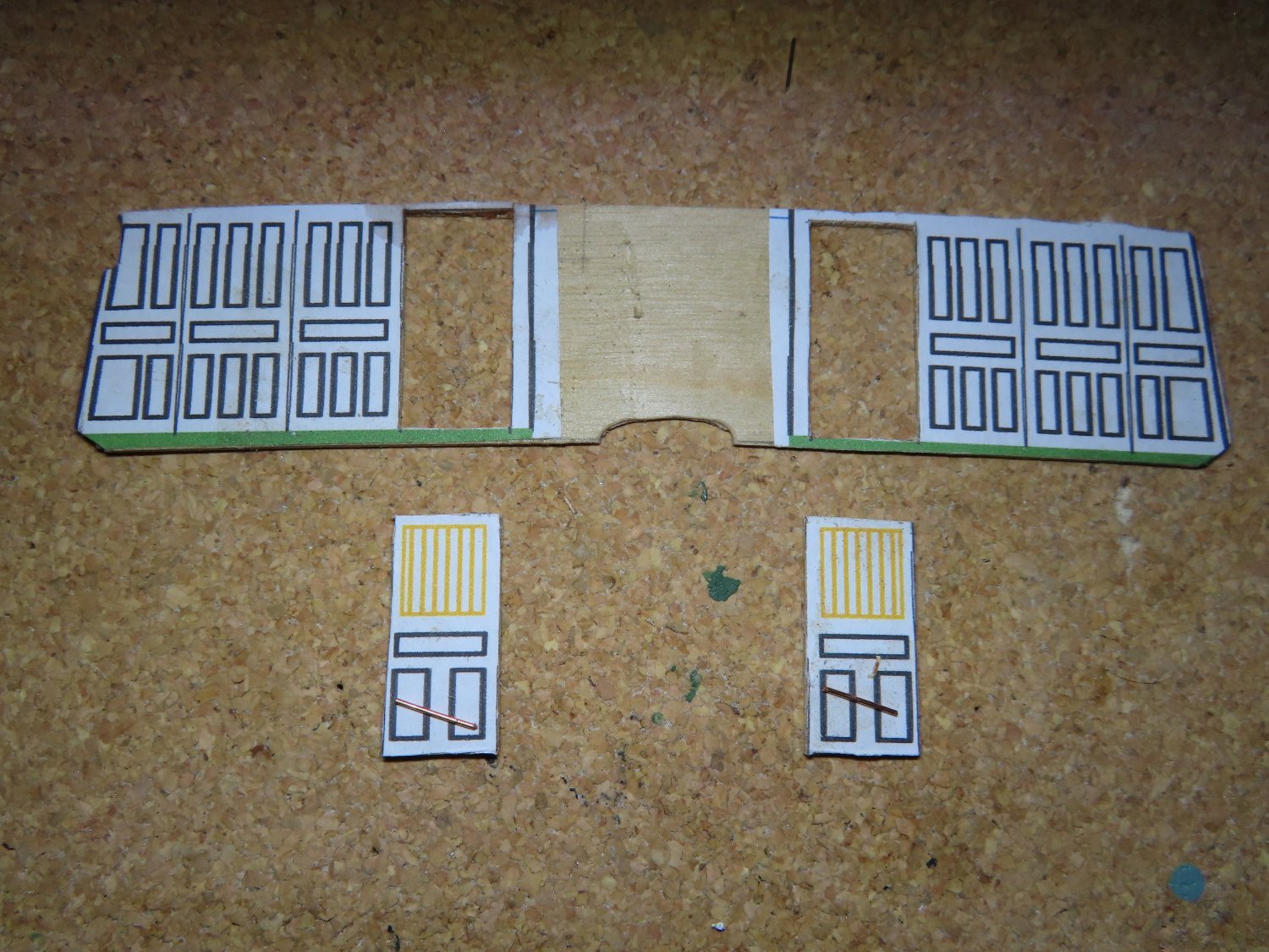
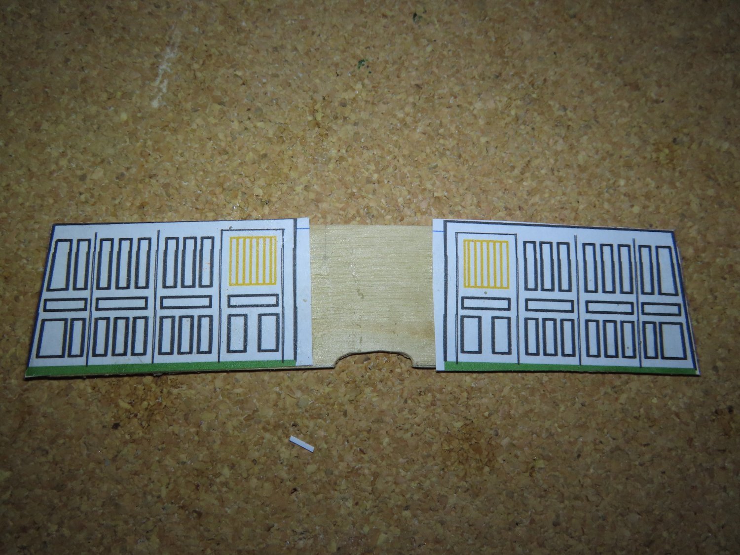
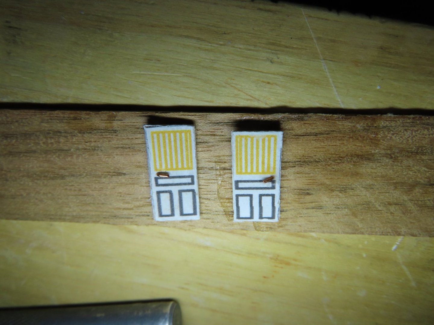
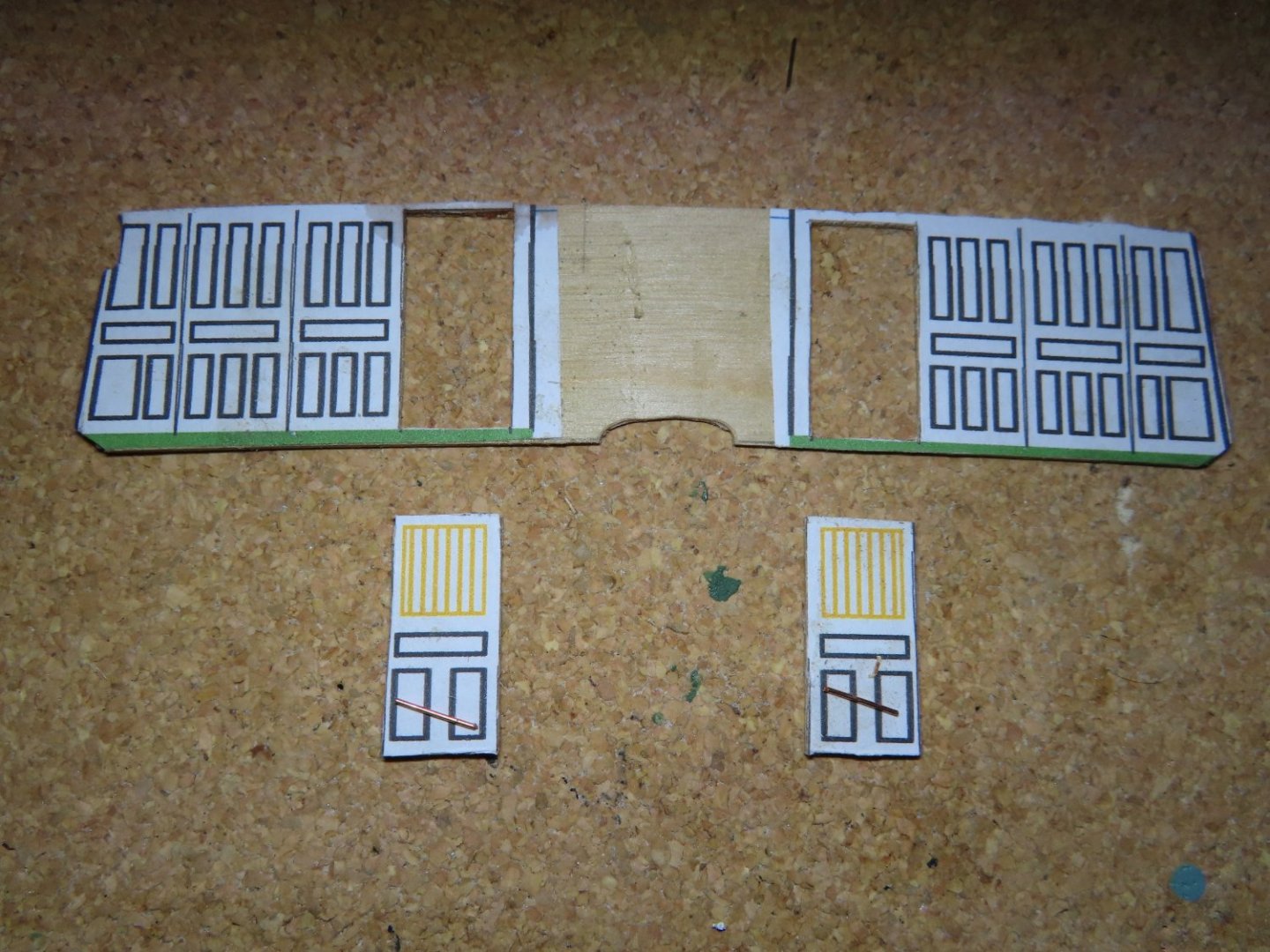
When I dry fitted the spar deck floor beam to the partition. I neglected to account for the effect it would have on the partition doors. I had drawn them too tall. Also, I noticed that the printed panels and doors were not to my liking, and the pasting work on the pantry front was not centered properly. So, all the printing and pasting had to be done over, as well as making new shorter doors.
-
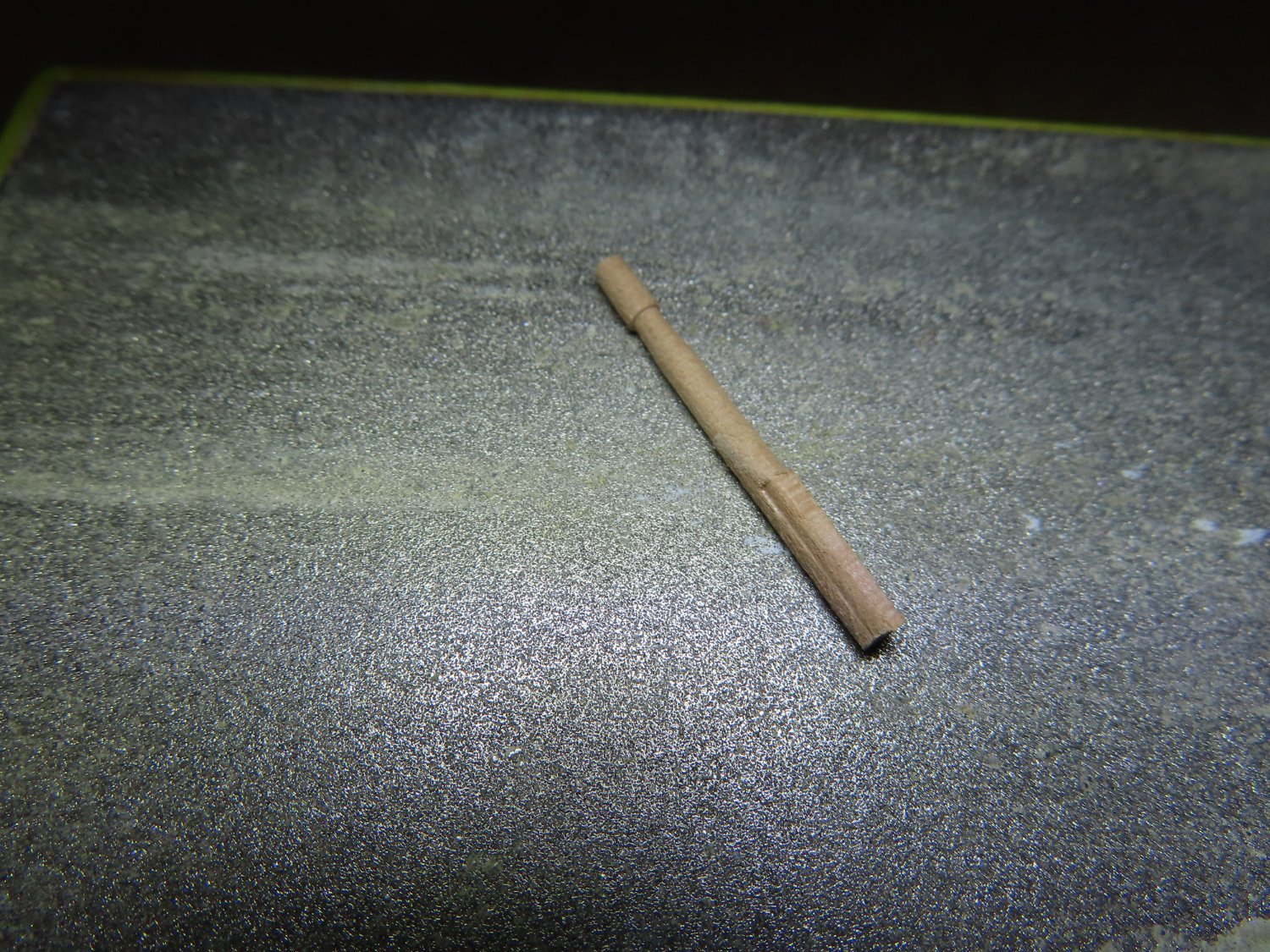
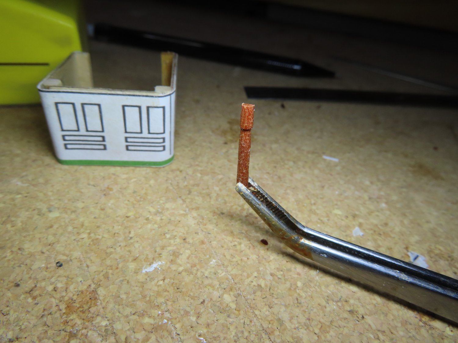
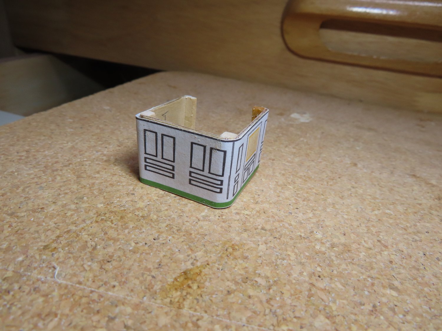
Half Column on Commodore’s Pantry The next component was the half column at the center of the forward end of the pantry. This was fabricated just like the column aft of the stove, however one side was flattened using a block sander until only a half column remained. The half column was then glued to the front of the pantry.
-
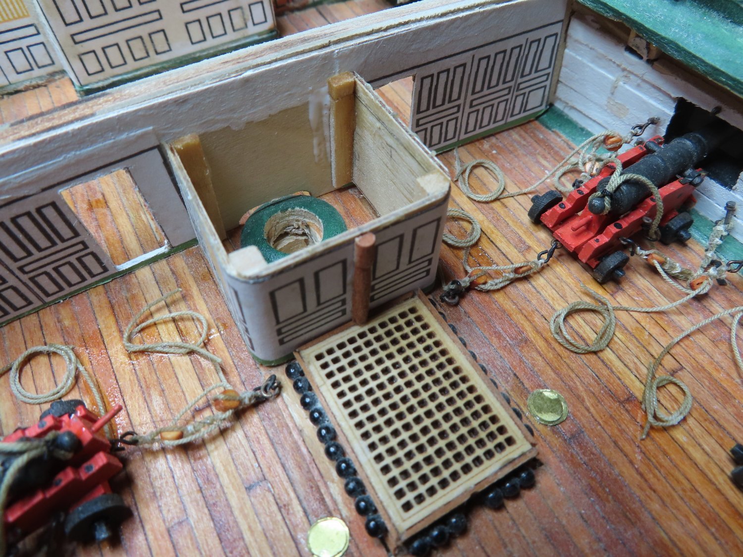
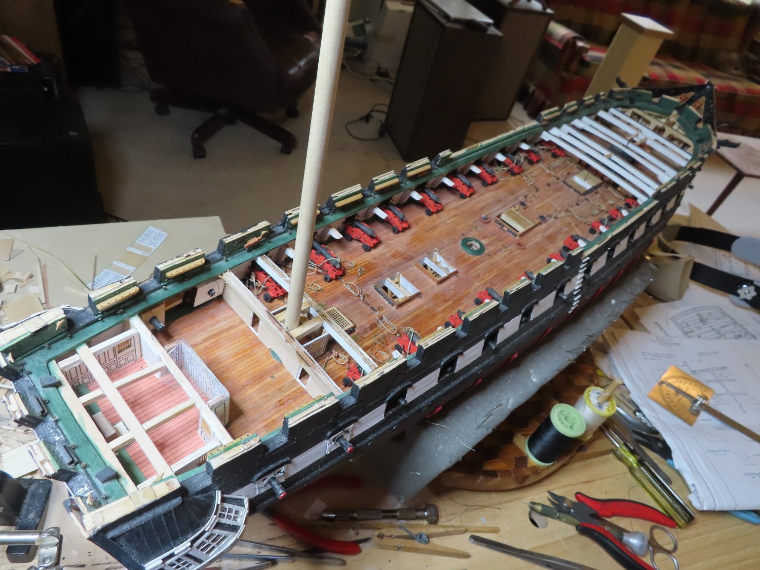
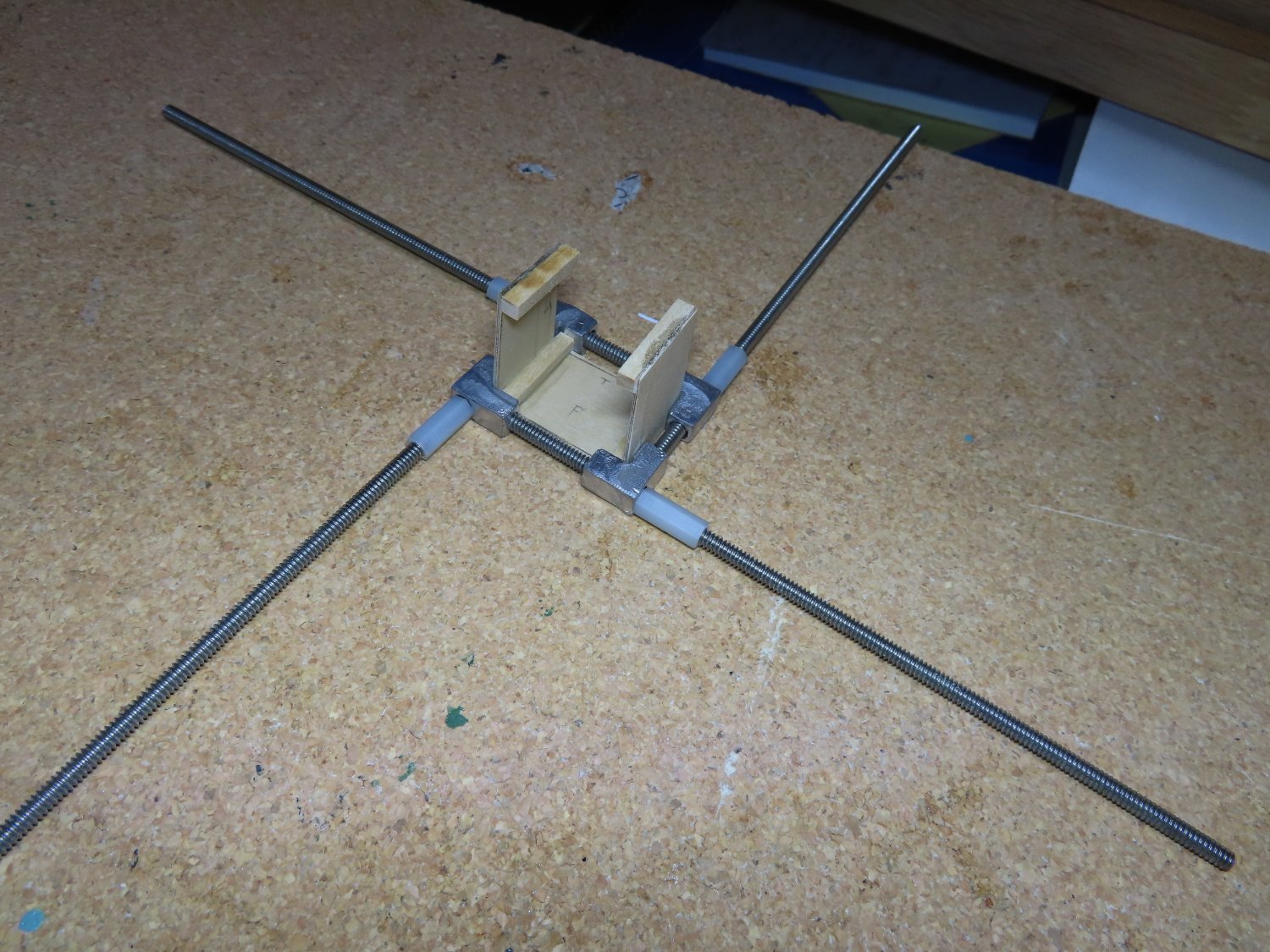
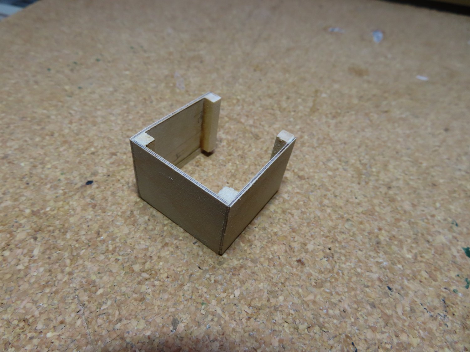
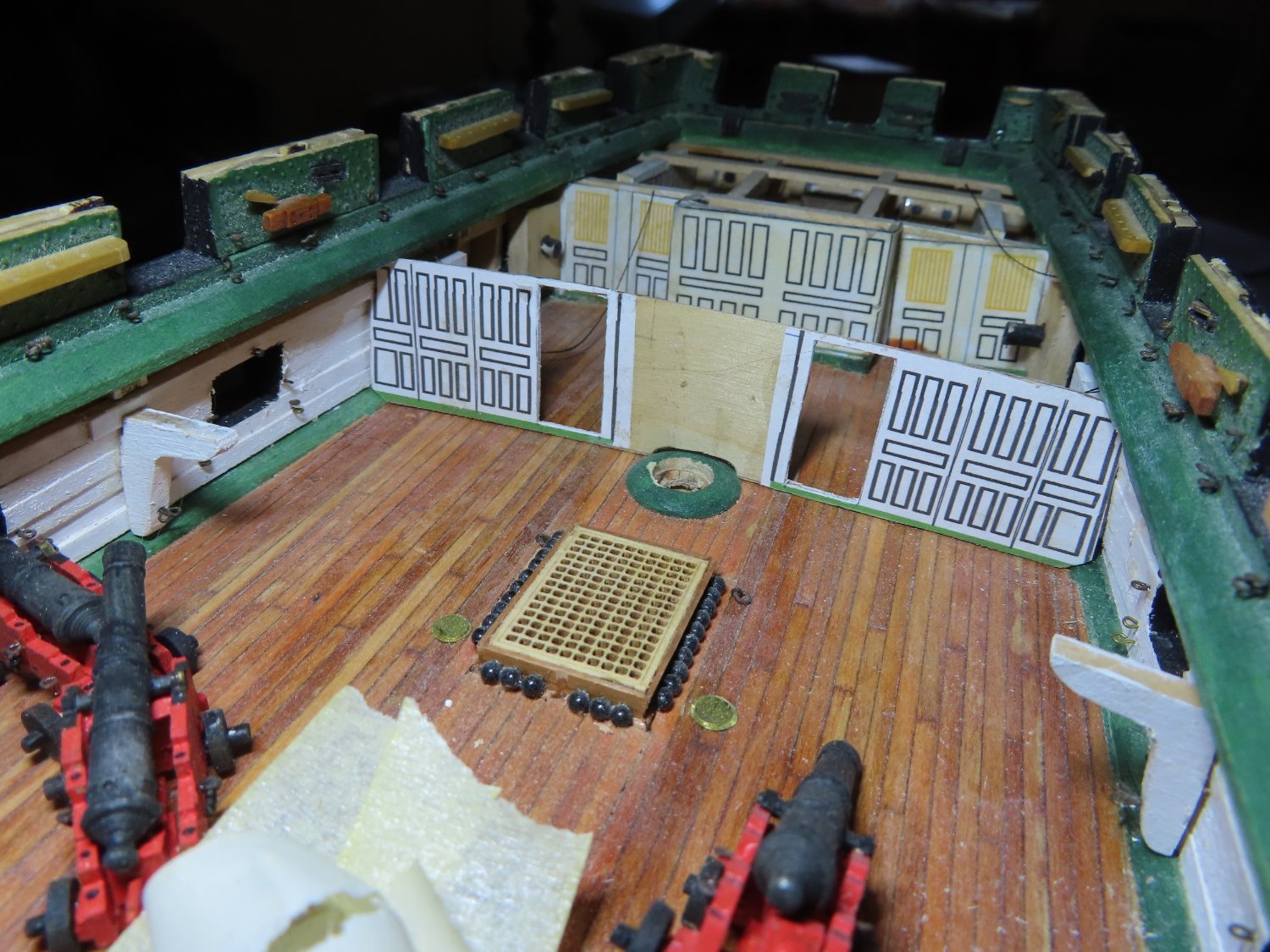
Construction of the Commodore’s pantry was made from three identical pieces of 1/32” plywood based on the US Navy plans and four vertical glueing surfaces. Using a four-way clamp, the three pantry walls were glued together. Next the two corners were filed to rounded them off. The partition was then dry fitted on the gun deck again for the image below.


-
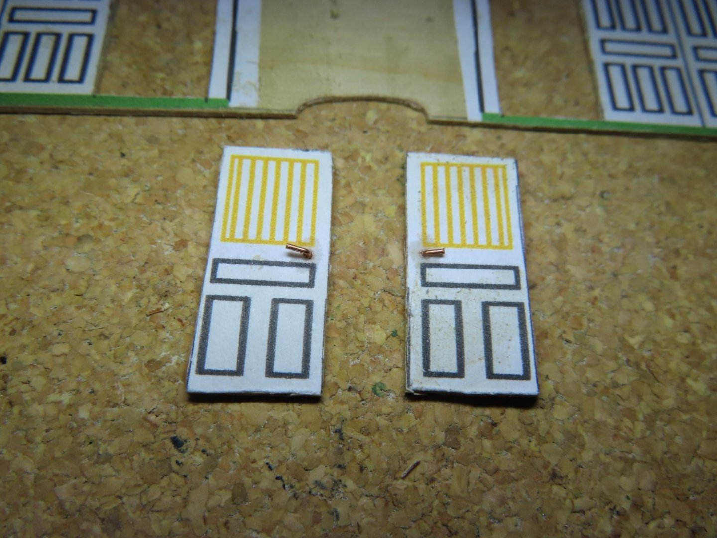
I cut the doors out of the plywood using an X-acto knife to add some depth in this space. Door handles were made from some bent wire to add some three dimensional detail. Should one be curious enough to look closely with a flashlight, the open doors will give a glimpse to the dining area. The open doors themselves will be added once the pantry is installed.

-
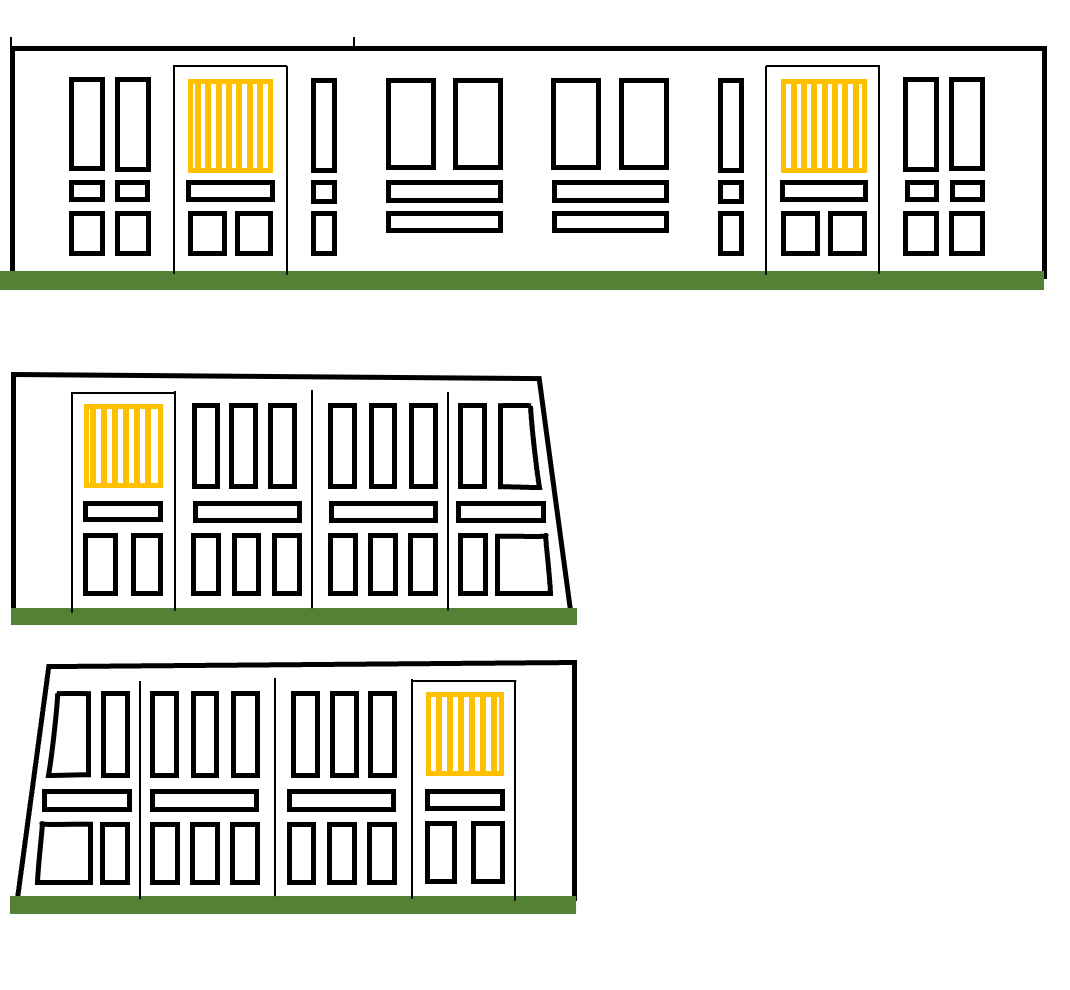
Using card stock, I made a template for the partition. Then, using 1/32” plywood, I fabricated the partition based on the template. Due to the expected confined viewing space and dark lighting inside the finished model, the partition and pantry walls details will not be seen clearly. Like I did for the captain’s cabin’s interior walls previously, I printed the details of the partition walls on paper using PowerPoint and pasted them onto 1/32” plywood.

-
Dining Area Partition and Commodore's Pantry Early in the build, I did not partition the dining room area from the main gun deck area; I was going to leave that open. Since the present configuration of the actual ship has the partition in place, I’ve decided to recreate that on my model. Additionally, I did not construct the Commodore’s Pantry which encompasses the mizzen mast on the gun deck. I thought at the time that I might need that area open to facilitate the seating the mizzen mast. If I sequence assembling the parts correctly, I don’t think that will be a problem. The partition and the pantry will connect to each other.
-
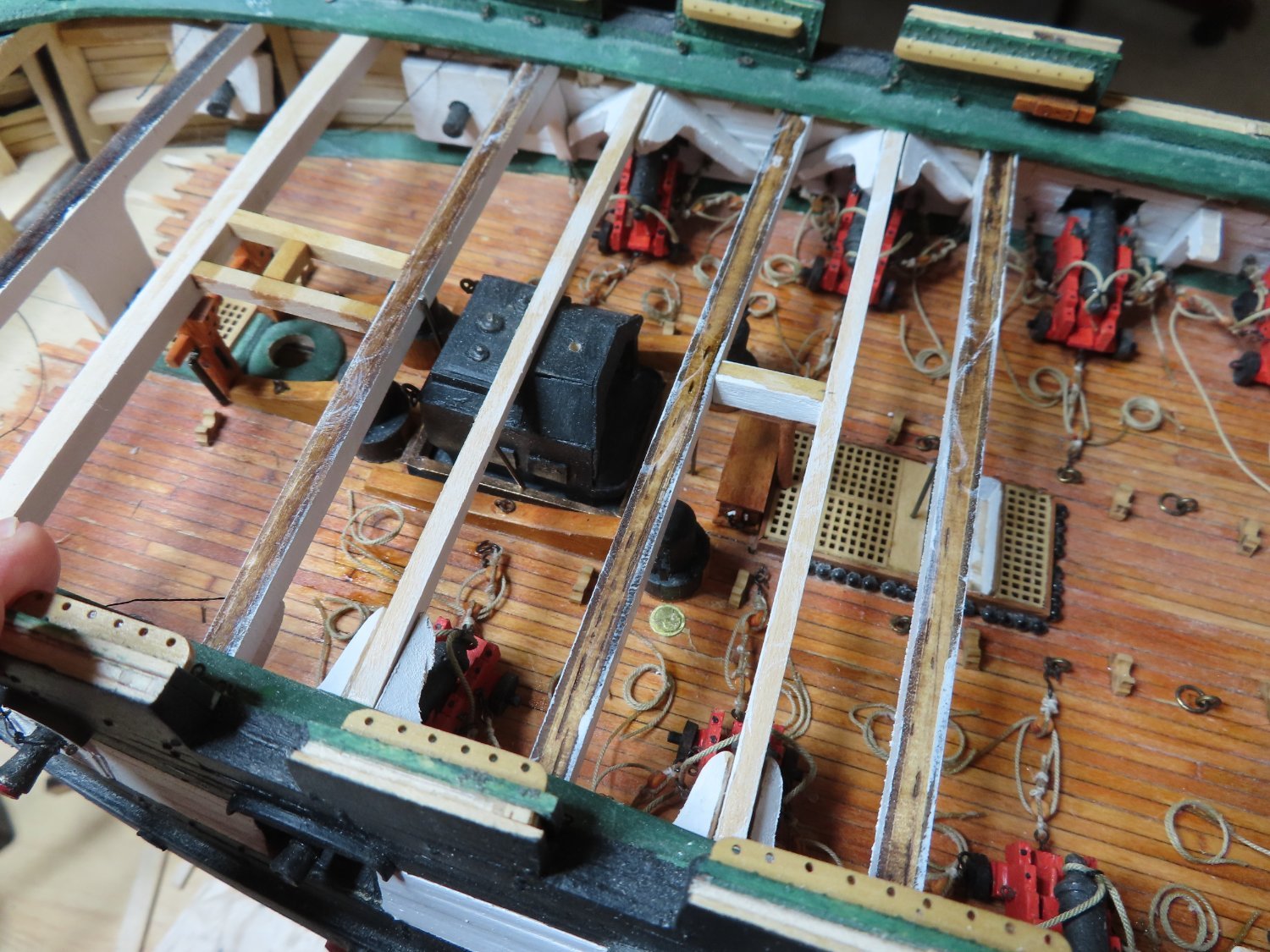
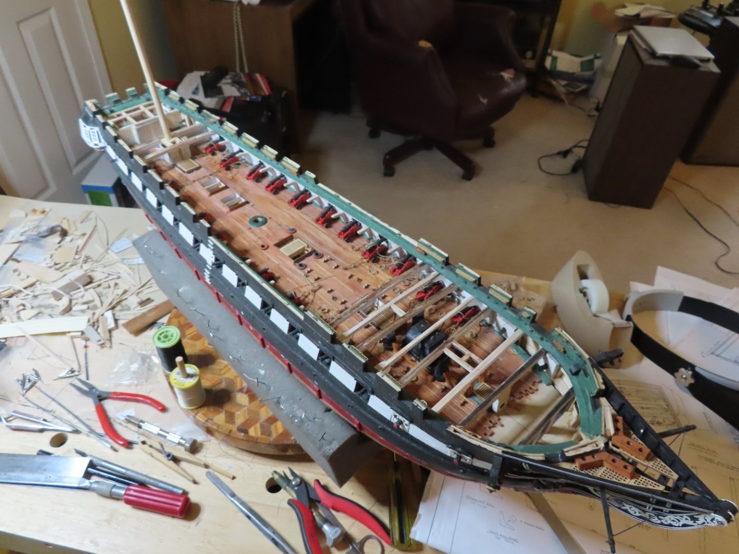
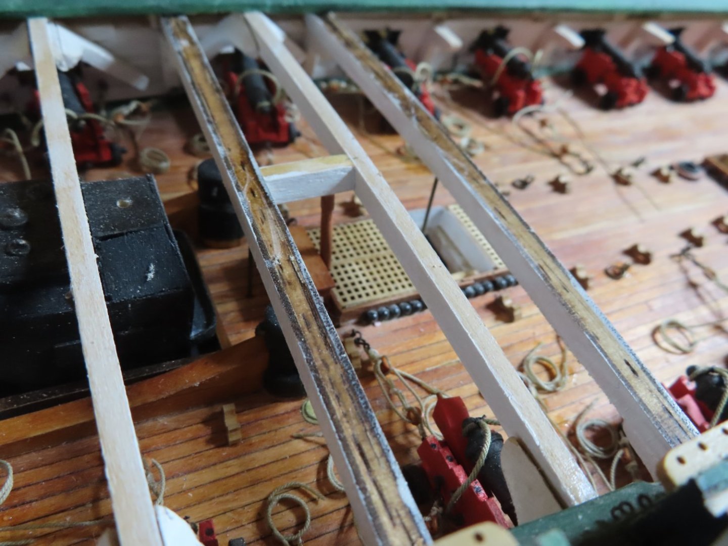
At this point, I’ve installed the main beams above the first two pairs of guns after the bow dummy guns. There are additional supplementary support beams between the main beams which I have not installed because this area will be mostly covered by the spar deck planking. However, as I progress aft, areas of the spar deck will be open to the gun deck for viewing. I haven’t decided whether to install some or none of these supplementary beams because they will substantially obscure the view of the gun deck. This last main beam (as you view the image) is just forward of the main hatch where the whale boat is to be stored on the spare deck. My original intension was to work aft from the bow adding the gun rigging, furniture, support stanchions and beams as I progressed. I have since decided to pause here and start work from the stern forward and pausing to construct the supports for the hatchways as I encounter them.

-
If you like creative uses of everyday items in model build, take a look this log devoted to just that: The Kit-Basher's Guide To The Galaxy Jon
-
USS Constitution by mtbediz - 1:76
JSGerson replied to mtbediz's topic in - Build logs for subjects built 1751 - 1800
Your chain looks very realistic. I didn't find that type of chain when I went looking a couple of years back. The chain I got is brass, so I will have to blacken it. Jon -
USS Constitution by mtbediz - 1:76
JSGerson replied to mtbediz's topic in - Build logs for subjects built 1751 - 1800
The kit provided a length of approximately 65cm of 10 links/cm plain chain. I purchased, some years ago, 90cm of 4 links/cm cross lug chain. The individual links are about 1 x 3 mm in size. I'm sorry, I didn't record where on the internet I got it from. Jon -
I have always stated that Mr. Hunt's practicums should be used as a GUIDE and not as the bible. The practicums are written as he is building his model, so not only do you see the problems he runs into, but more importantly, WHEN he realizes he has a problem and he has to fix it. If you follow him step by step, you will make the same mistake and have to fix it like he did. He did not go back to edit the practicum to warn the reader of the impending pitfall. You will also find that he does not always complete his model, but talks his way to the finish. That being said, I could not have started, let alone build, my Rattlesnake or presently, the USS Constitution with out his help. Jon