JSGerson
-
Posts
2,633 -
Joined
-
Last visited
Content Type
Profiles
Forums
Gallery
Events
Everything posted by JSGerson
-
 All 22 carriages are painted, now awaiting metal accoutrements such as eyebolts and rings.
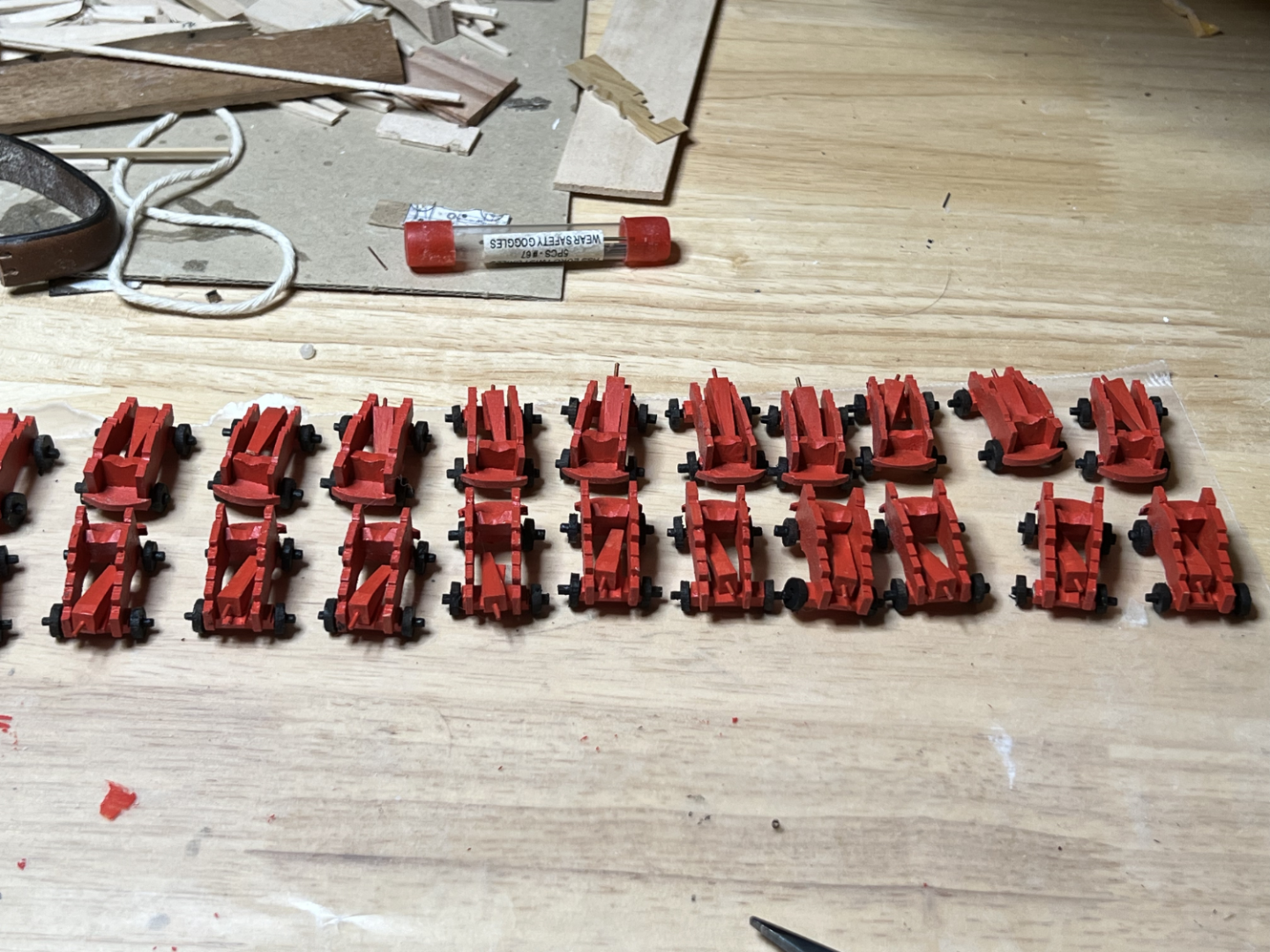


-
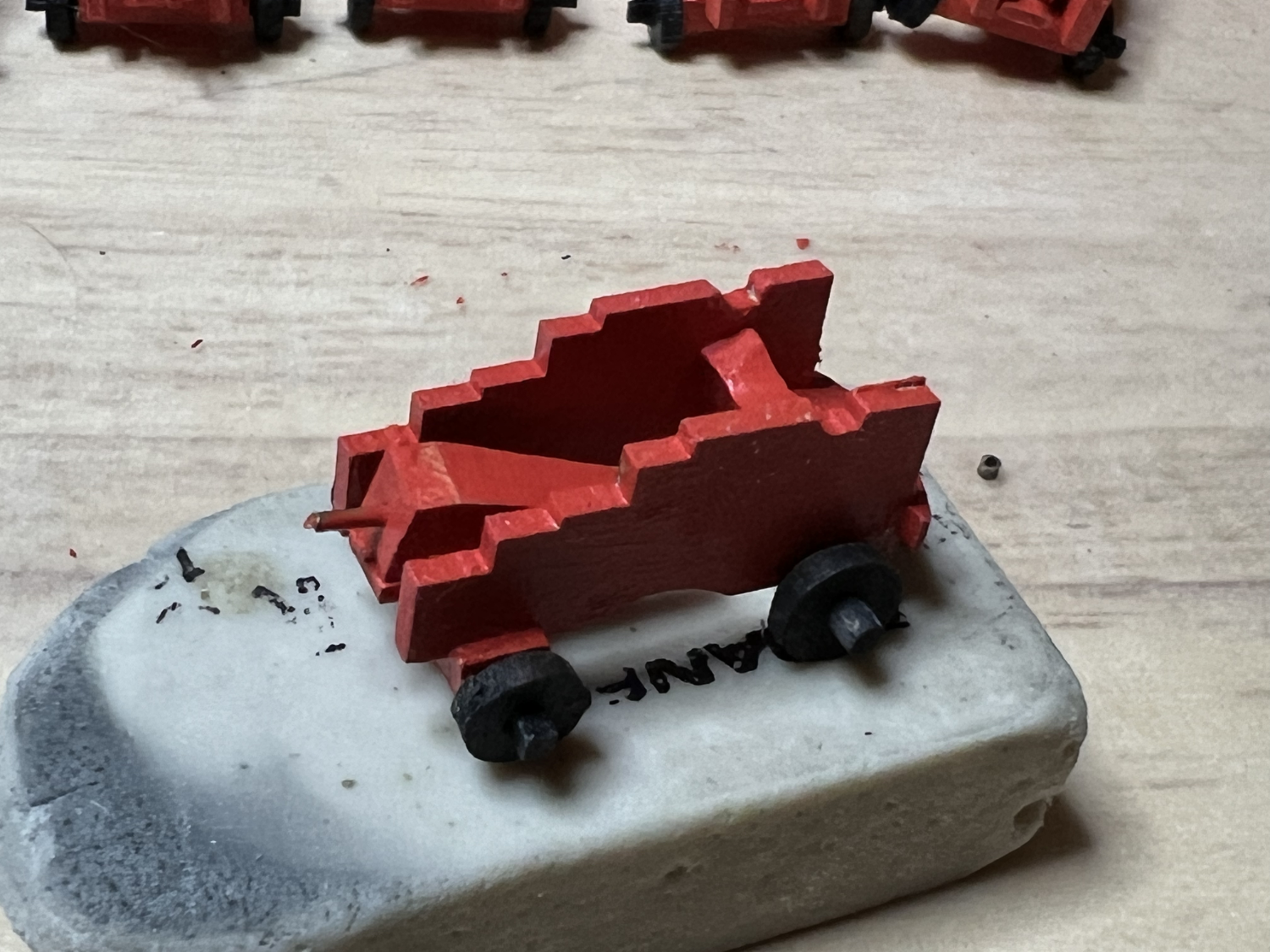
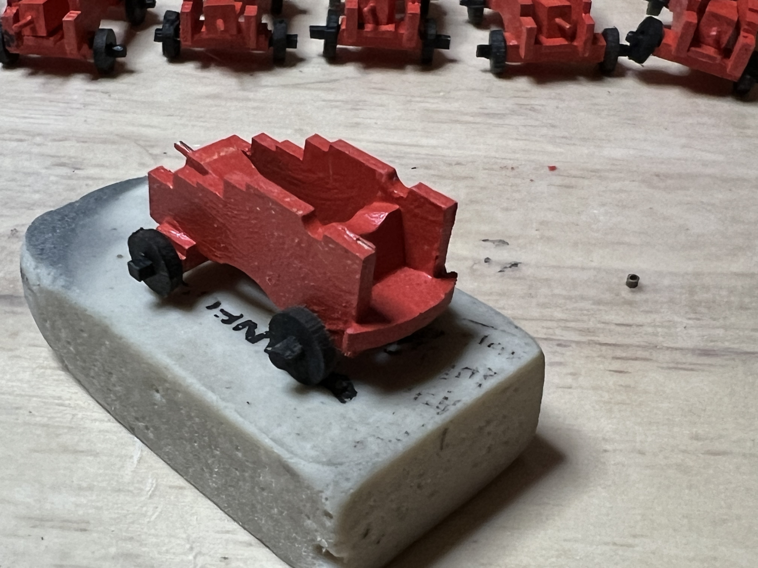
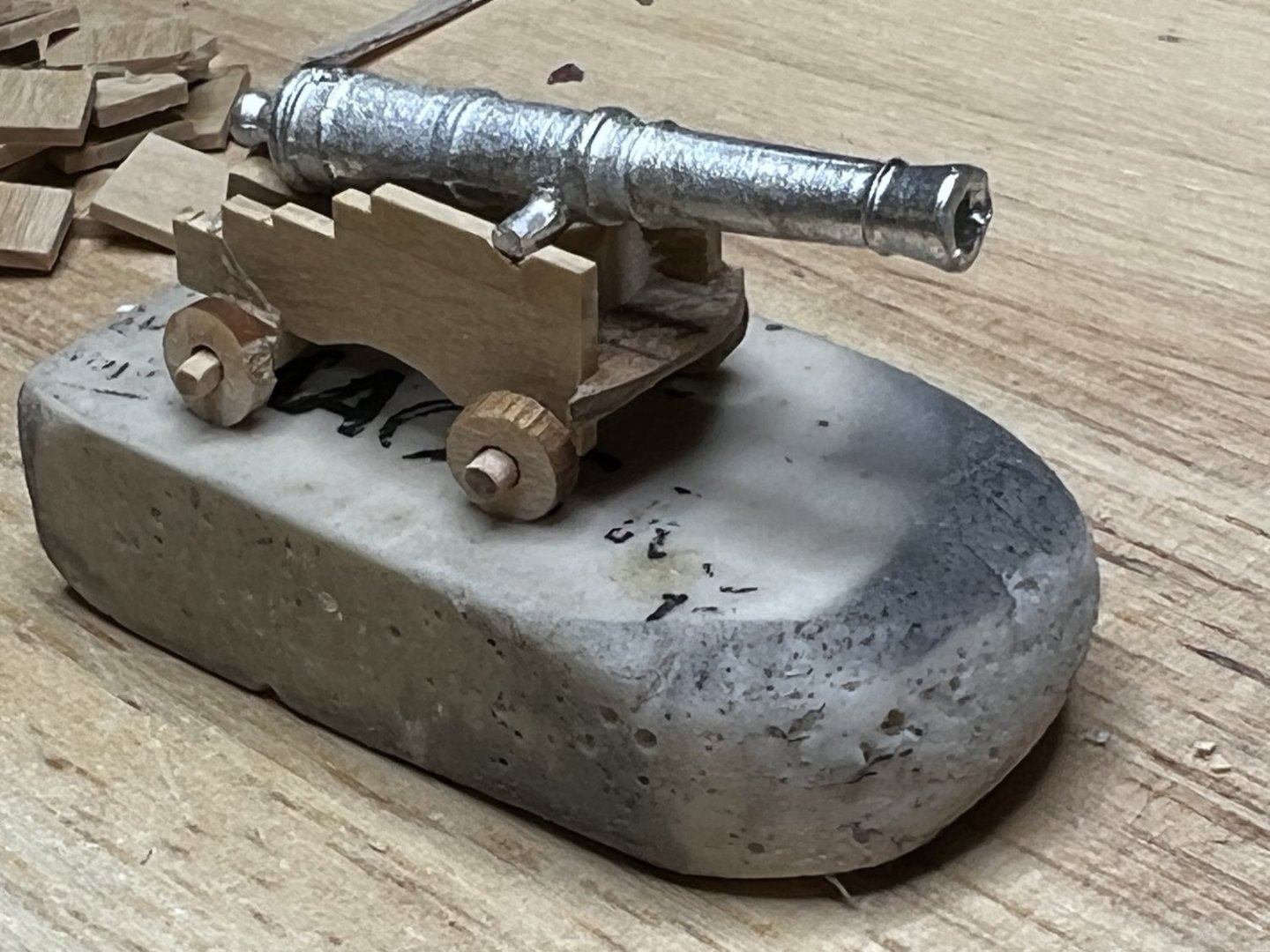
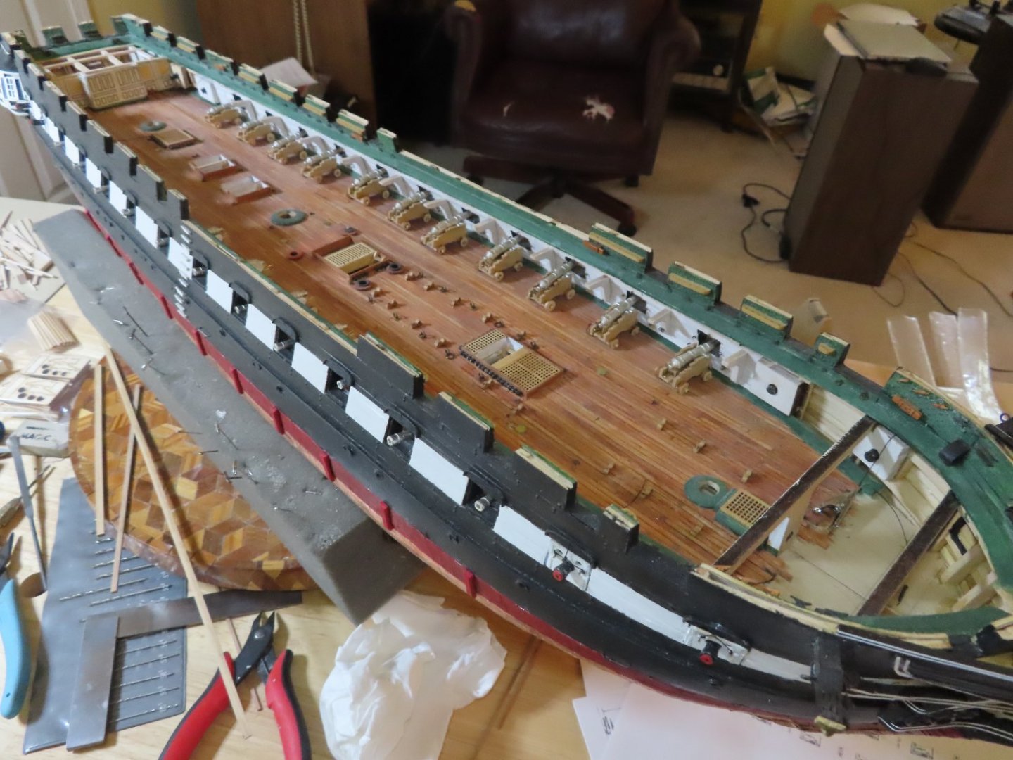
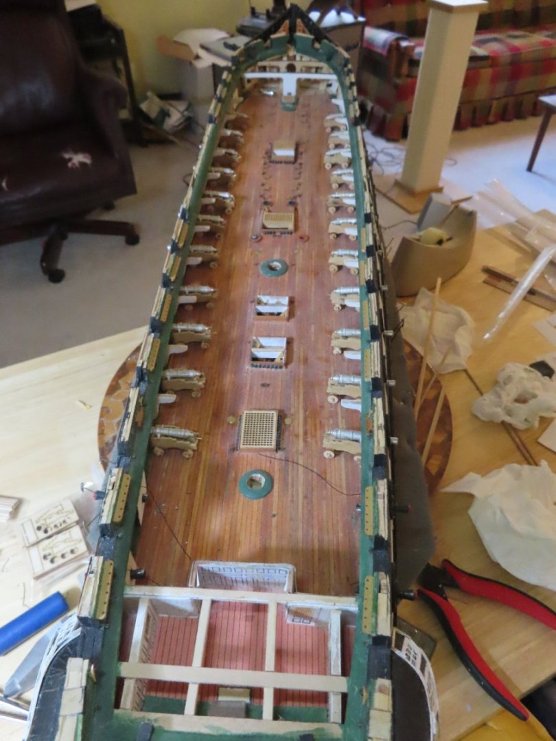
Well, I’ve finally completed fabricating the gun carriages and glued together all the wooden parts save for the quoins. BTW, the quoins shown in the photos below did not have their handles installed at the time of the photo shoot. They were made from 0.032” brass rod. I’ll glue those down for the final adjustment of the gun barrels, after the carriages are completed. Next up, is painting the carriage bodies red and the axials and wheels black. Still to come are the addition of the metal hardware and rigging. To give myself a preview, I’ve temporarily placed the gun assemblies in their positions on the gun deck.
-
Without seeing your situation, I would use CA glue provided you have enough surface area to glue and that the surfaces to be glued are clean. Jon
-
Peter, at the bottom of MS webpage, there is a button for "parts request." Also I have listed their phone number as (800) 222-3876. I don't know if this number is still viable as I haven't had a need to use it for quite some time. BTW, if you ever buy just one hobby power tool, The Byrnes saw is worth every penny. Jon
-
I looked at Rich's log and his cathead sculpture looks a little oversized. The sculpture edges should be flush to the cathead. Therefore, the 1:87 Constructo sculpture might be just the right size for the larger scale 1:76.8 MS kit. Luckily, only a knowledgeable viewer would be aware that the Rich's and my sculptures are not the same as the actual ship. When you think about it, I'm really surprise the MS kit does not supply a precast sculpture. Jon
-
Those cannons are coming in very handy right now. Thanks again for making them available. Jon
-
I thought I would bring the conversation of the cathead carvings back to your log instead of continuing on Unegawahya's log. I was getting a bit confusing as to who I was commenting to. How to create the cathead sculpture: As I mentioned on Unegawahya's log, there are only two ways. Either carve them yourself, or purchase a similar one online which I did. If you are going to attempt a carving, you might want to look at xKen's (Ken Forman) completed log starting at Post # 756. He's a professional model maker and it worth looking at his complete log. His is a true carving out of wood. An alternative to that method, is to use Scuptey, a clay like substance that is baked once the sculpture is made. I saw this done, but can't remember who did it that way. Jon
-
As you have discovered, the Model Shipway kit does NOT provide a cathead carving. Either you carve your own like I think Unegawahya did, or "cheat" like I did using something similar that will work at this scale. This is what I used from, AliExpress. Unless your nose is 6" away, the viewer can't tell the difference.
-
Just discovered your build today and I feel honored that you took some inspiration from my build log. The USS Constitution model is not for the faint of heart. You need strong wooden boat building experience for this project. And you had enough confidence that you could build this with one hand tied behind your back. I am humbled and my hat is off to you sir. I look forward to your future posts. Jon
-
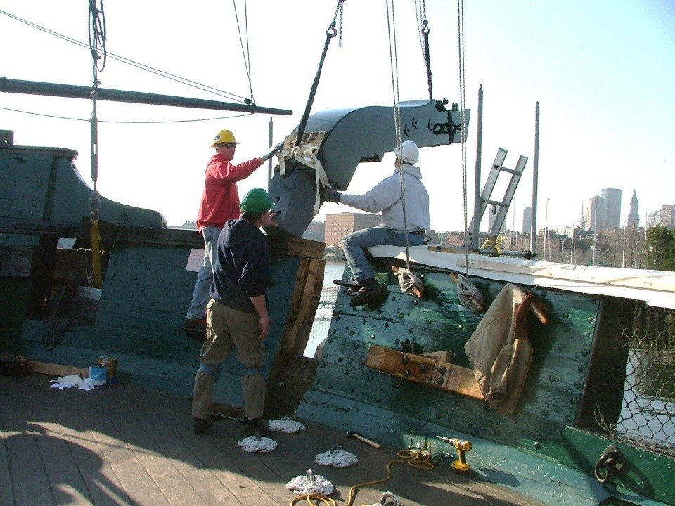
Here is a picture of the cathead being installed on the actual ship. Hopefully this will answer any lingering questions on how it is suppose to be done. In my case, the cathead was glued flush to the waterway and not into it. I felt cutting the already installed waterway would be too messy and could possible damage it. The resulting visual effect was the same. Jon
-
Here is what I did. I did not follow the Practicum. Jon
-
I suppose that is good and bad. It was not my intent to instigate a "do over," but if it does provide you the satisfaction of a job well done in the end, then I'm happy. I know how it feels because I've been down this road before. Jon
-
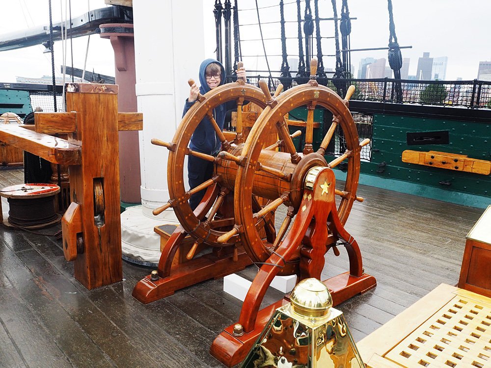
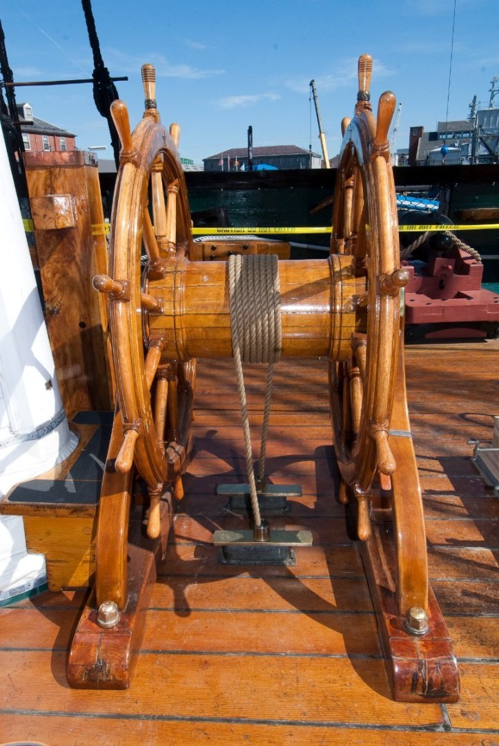
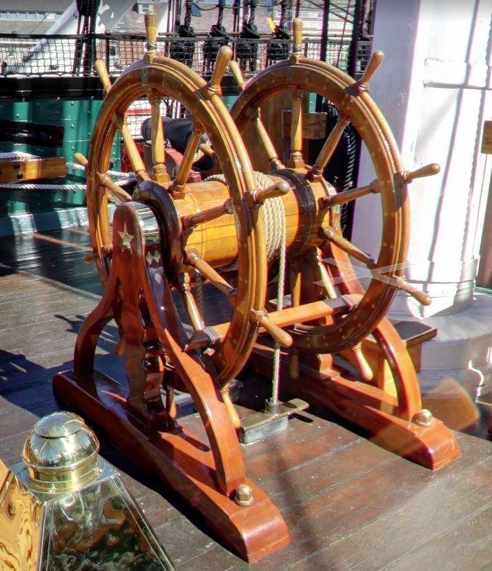
I checked the practicum for you and Bob used the kit's metal wheels but fabricated the the stand and "barrel" (the spindle in between the two wheels out of styrene because the laser cut wood that came with the kit was too fragile. Not what I wanted to do. I did some digging in my own library which you can see in the photos below and a CAD drawing of the wheels (don't remembers where I found it). Should you need something, just ask. Jon Constitution Double Ships Wheel.pdf
-
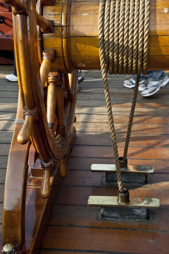
I'm fascinated by your ship's wheel fabrication as you can tell from my comments, so continuing on this theme, how did you fabricate the section between the wheels? It appears that the dowel between the wheels is built up somehow in the image. I haven't looked at the plans or the practicum at this point as to how they wanted this done so I don't know if you are following them or you did something else. Jon
-
Magnificent work! I was however, confused by your statement: "To form the wheel I layered two more layers on the first. Each layer was offset by one third of the wheel." Offset how? I'm not sure what you mean. As for not having a lathe, I don't think you need one for this delicate work. I use my cordless Dremel variable speed rotary tool for the small delicate stuff,. With just a file on the spinning material, you can produce some amazing things. It's how I made the cleats from a nail I used in the seat of ease area. Jon
-
Wonderful. I thought we may have had another incomplete build. Good to hear you'll back. Jon
-
I'm impressed with your ship's wheel. How long did you have to soak in (I assume water) the basswood to get it flexible enough to wrap it around the 3/4" socket? How did you drill the holes for the spokes without breaking the narrow rings and so precisely? I repeat, very impressive. I too plan on substituting wooden wheels for the kit supplied cast metal one, but instead of a total scratch build which I wasn't sure I could pull off, I bought a couple of ship wheel kits from Syren Ship Model Co. last year or so which are substantially more complicated that your elegant method. We'll see what happens. Jon
-
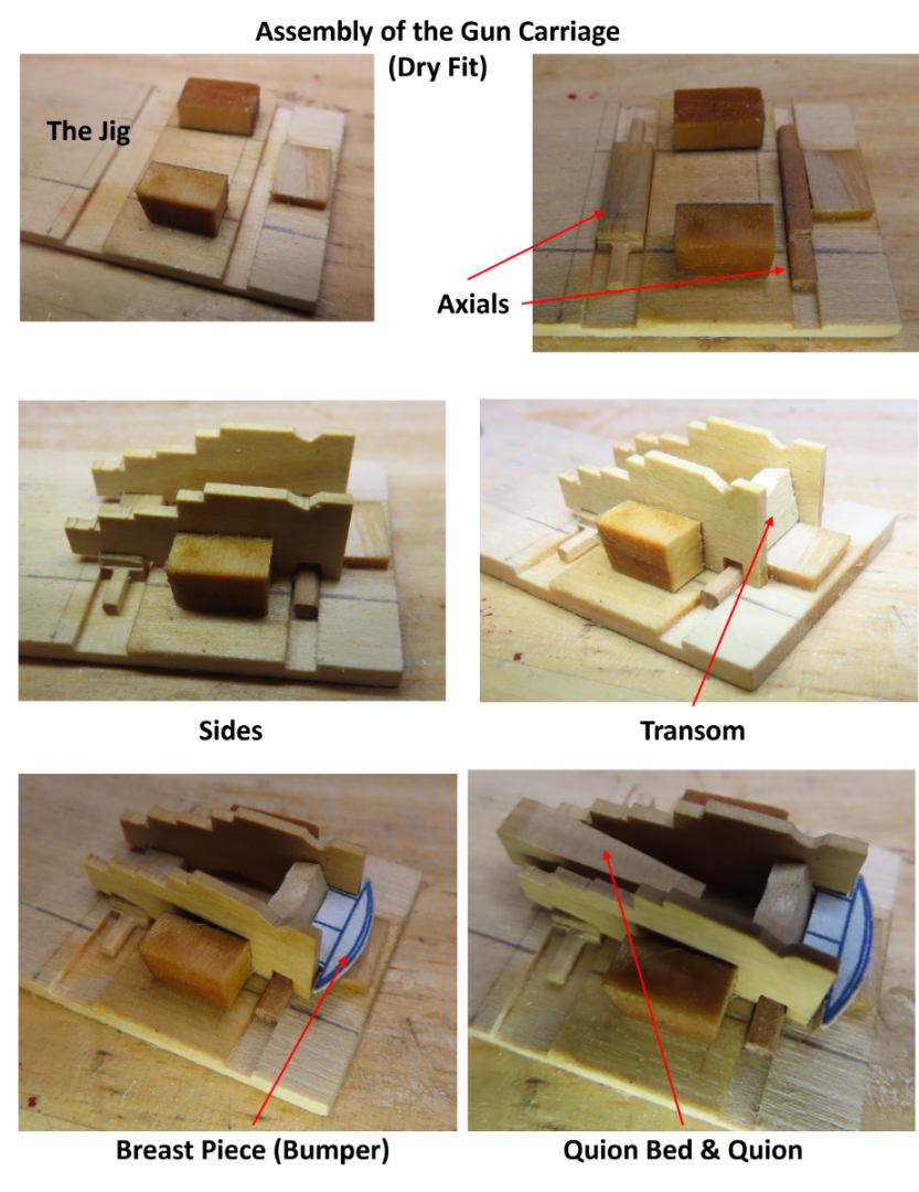
Thanks for looking in. The jig actual builds itself, just look at all three of us. You, me, and bthoe have virtually the same jig due to the the logic of the carriage assembly. It's just good engineering. I thought about the canopy glue, but just didn't have any on hand. I keep forgetting to get some. I'll get it done at some point. Jon
-
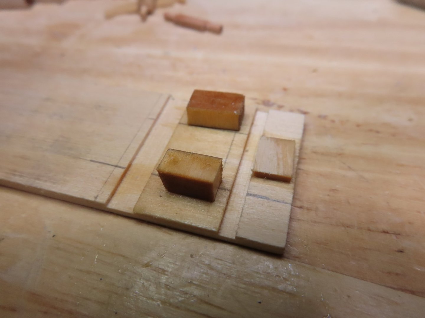
To put together 22 gun carriages simply and consistently, a simple jig was made that held the various pieces in their proper positions. Shown below is my first attempt at a dry fit. Now I must assemble and glue all 22 carriages.
-
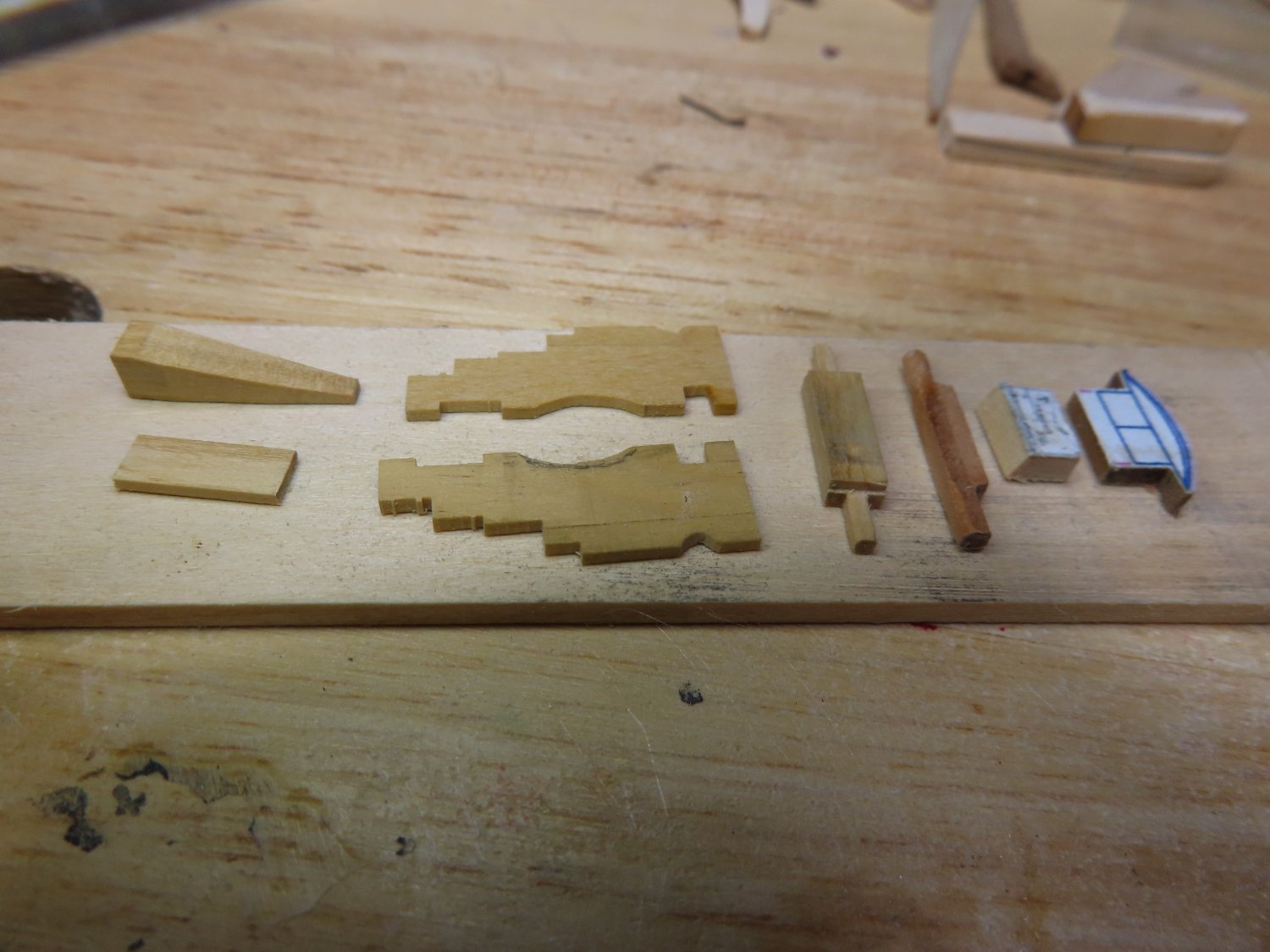
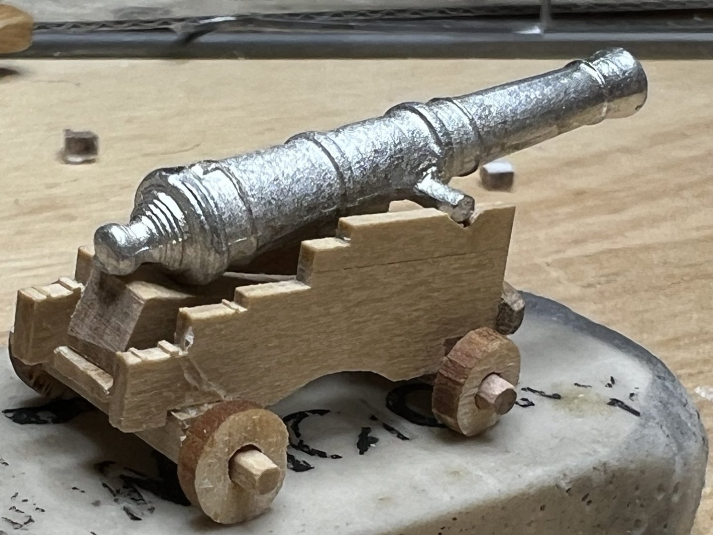
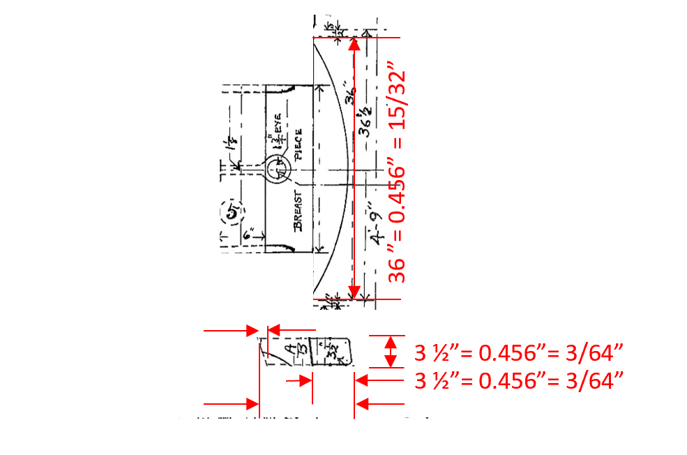
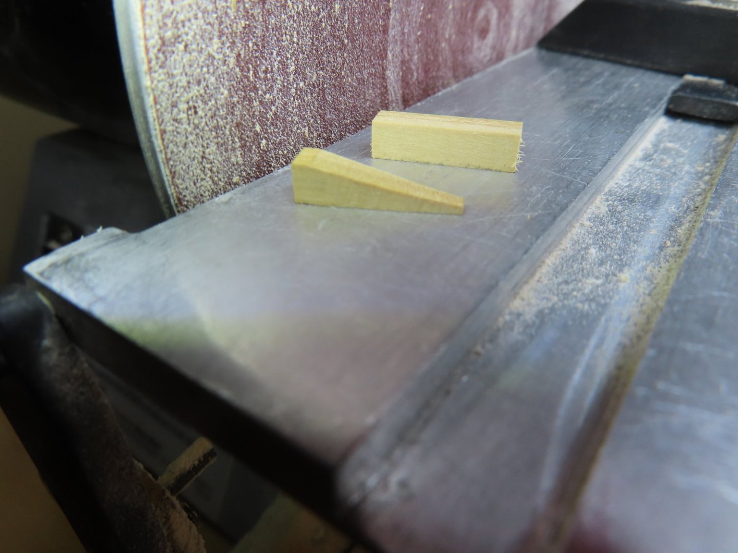
The remainder of the gun carriage pieces were much simpler to fabricate. Pretty much just slicing pieces of wood to length or cutting out the pieces using templates made from the US Navy plan. To create the Quion, a disk sander was used. Note: The US Navy plan uses the term “Coin” for Quion.


-
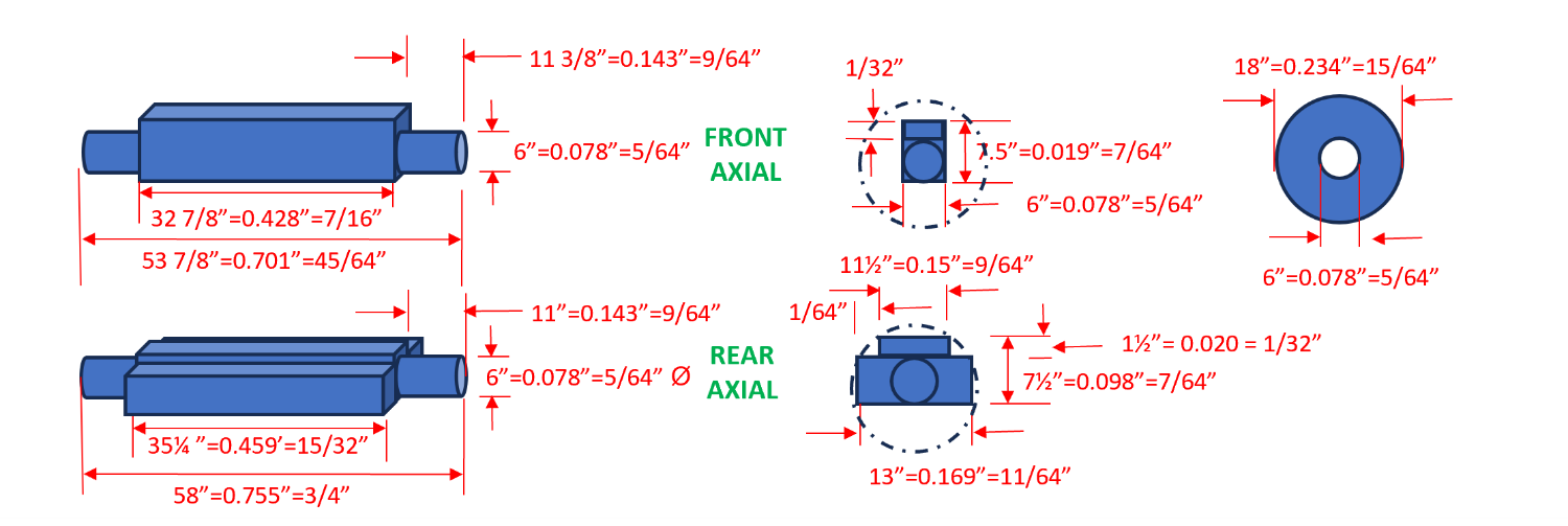
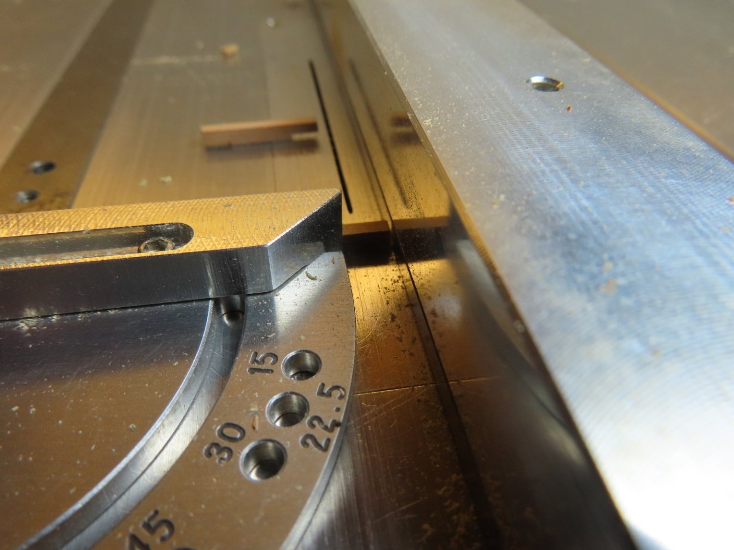
Continuing, the axials were the next carriage parts fabricated. The axials act both as the wheel support with the typical circle cross section at the ends and as the support for the carriage sides which rests directly on the square or rectangular cross sections interior portions. It appears that the fore and aft axials are fabricated out of single pieces of lumber. Due to the small scale, the resulting shapes have been simplified slightly from my original design sketches. As I was trying to wrap my head on the fabrication process, I ran across bthoe’s wonderful build in which he did the exact same thing for his carriages. I had forgotten about his build as he hasn’t posted since November 2022. For the most part, he and I basically came up with the same carriage pieces dimensions within 1/64” of each other. Stock boxwood was properly sized to the desired profile for the fore and aft axials on the Byrnes saw. Then 22 pieces of boxwood for each axial were cut from the applicable axial boxwood. Utilizing the fine 1/32” width slicing blade, each axial piece was trimmed at the ends to create the truck wheel portion of the axial.


-
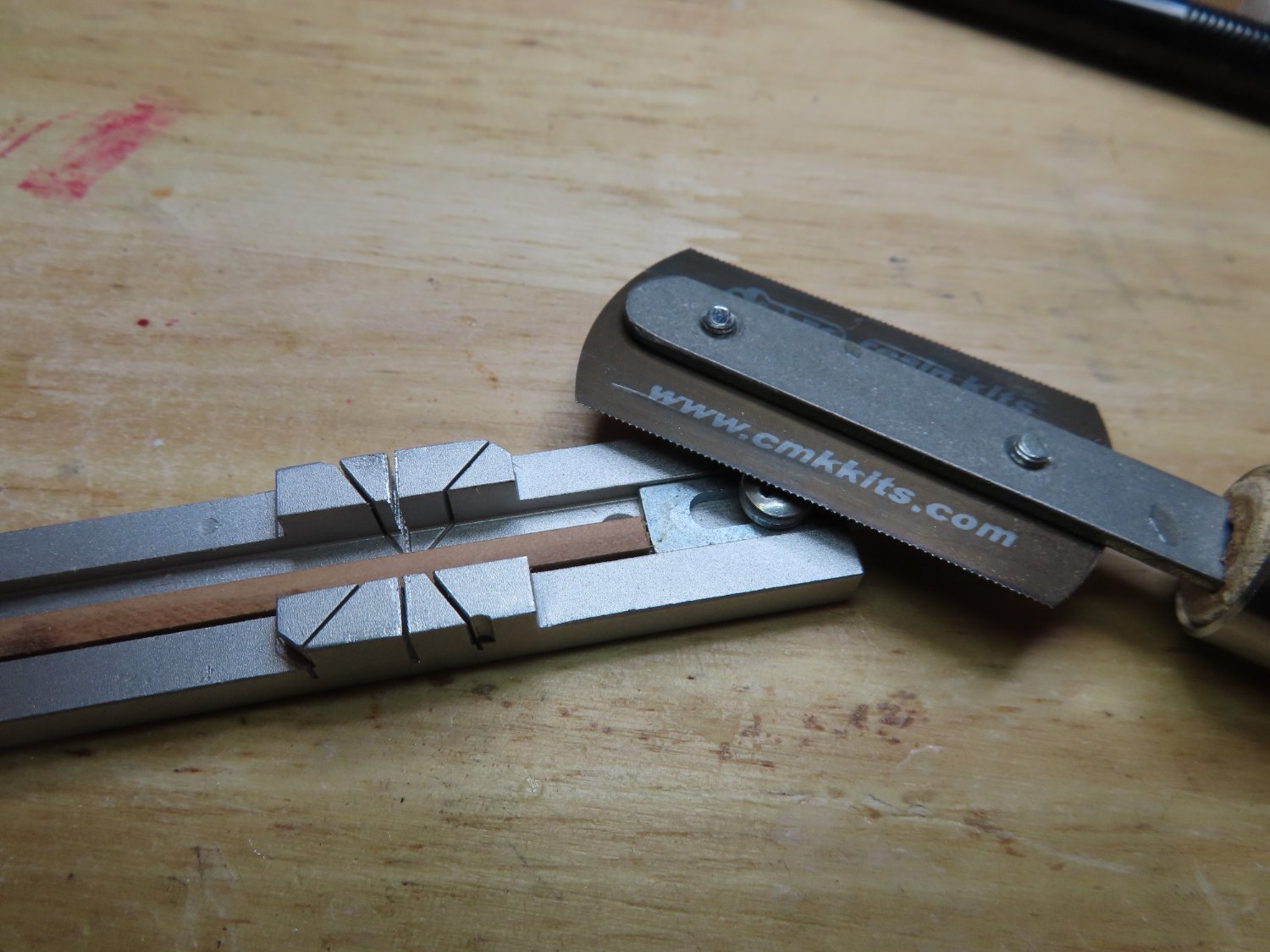
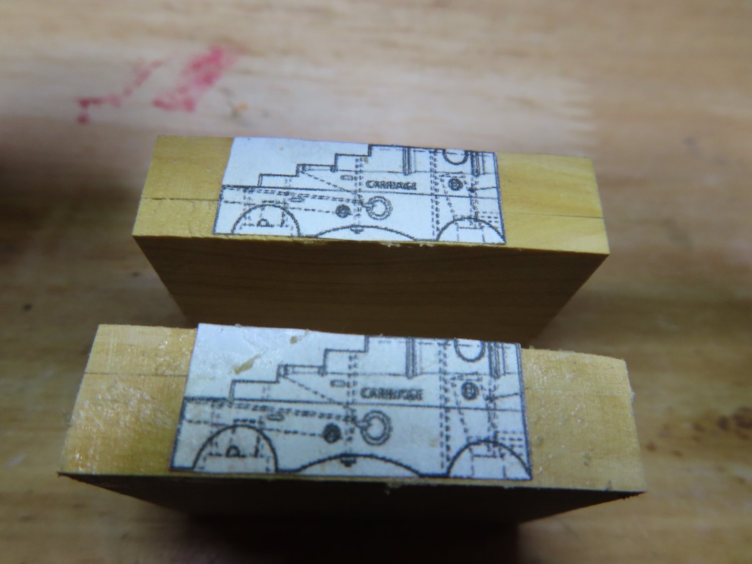
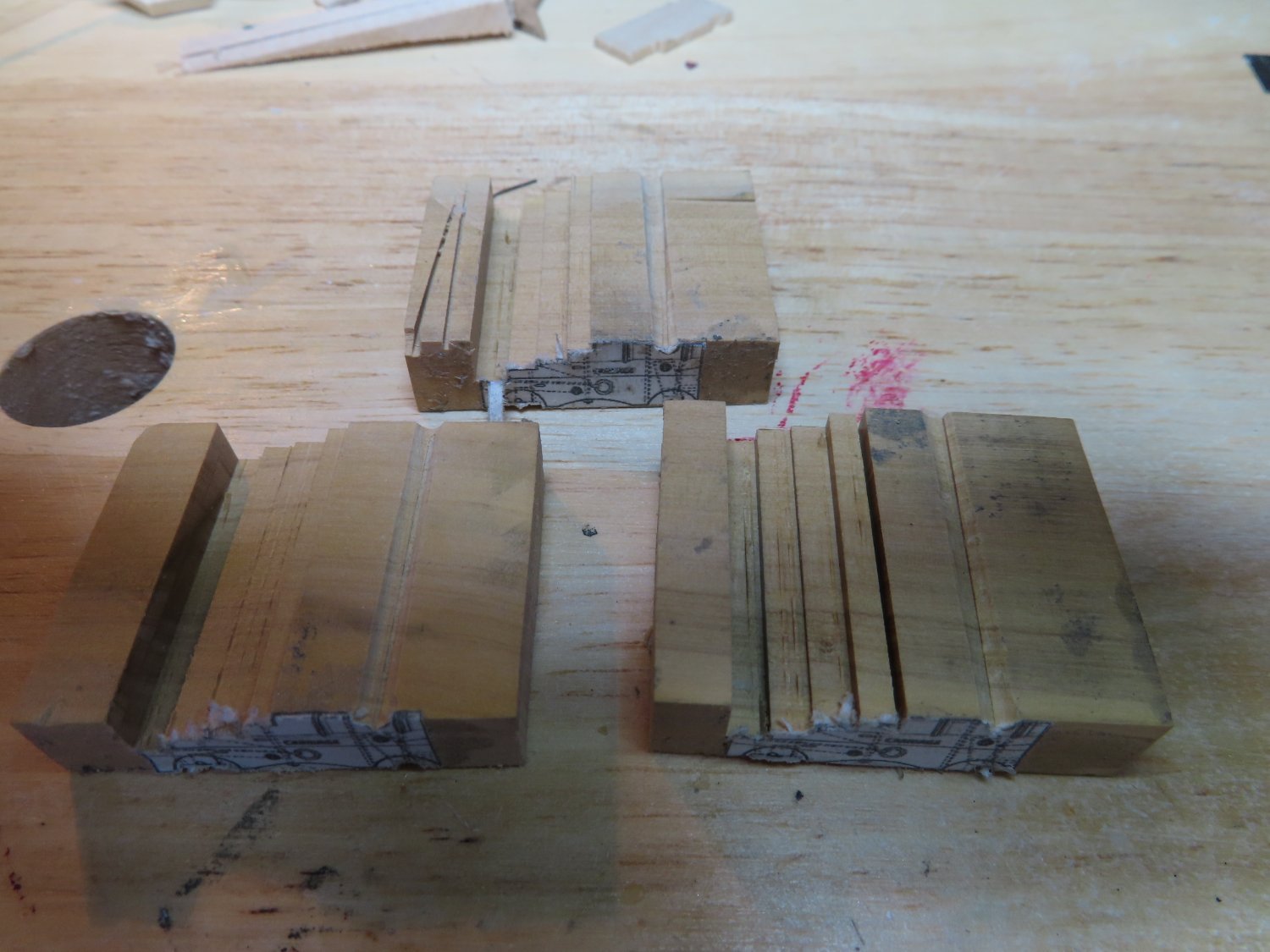
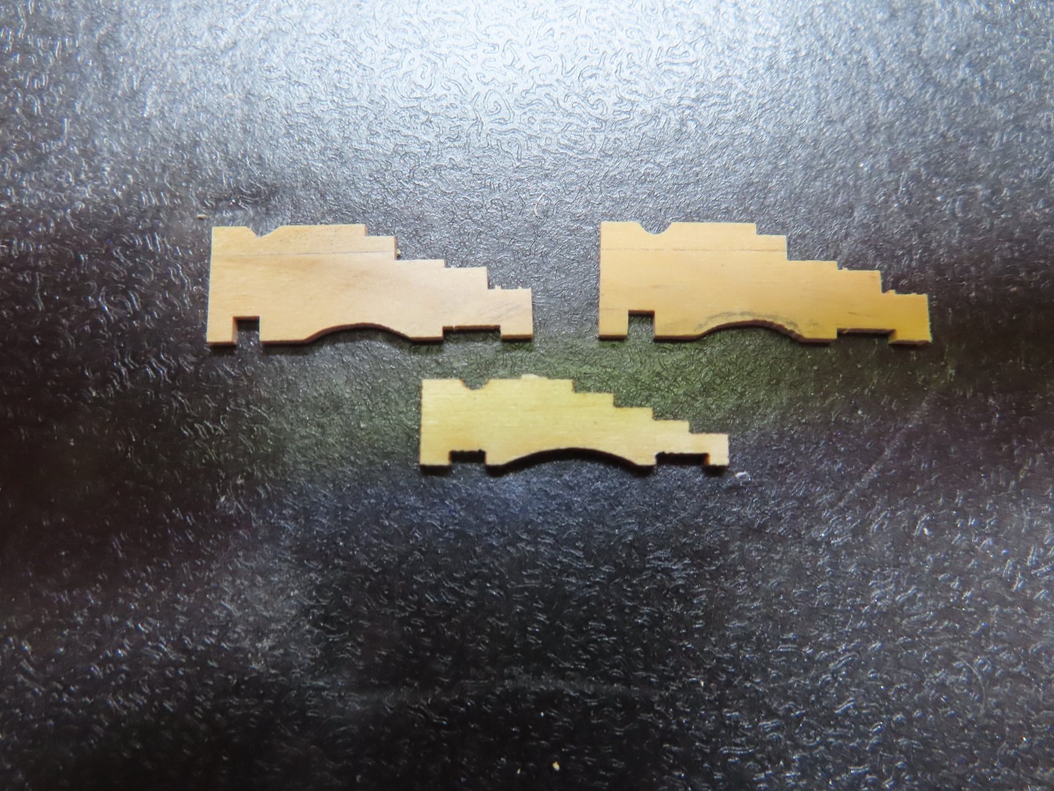
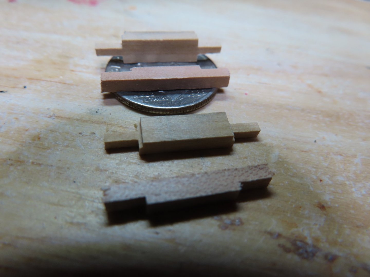
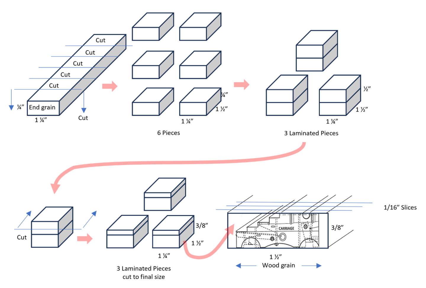
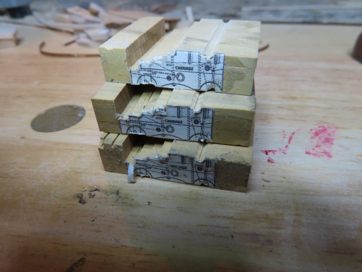
Gun Deck Gun Carriage Fabrication First, I did some research with the 1907 US Navy plan No 14939 (sheet No.:3103) 24 Pdr Gun and Gun Carriage to determine the proper carriage dimensions. This revealed that I needed as a minimum a piece of wood 15/16” wide x 5/16” tall to create the carriage sides. The plan was to cut the carriage profile into the wood block such that I could cut 1/16” slices from it like a loaf of bread creating the sides of the carriage. 44 sides at 1/16” thick required a length of wood almost 3” long. I chose boxwood for this task because it will hold a clean-cut edge and is not as fragile as basswood. However, because I did not have a piece of boxwood of those dimensions, I had to laminate two pieces of 1¼” wide x ¼” thick wood together to get the required height. I could have cut the wood stock 3” in length to make one laminate block, but that would have meant that the resulting carriage sides were cut cross grain. I wanted the side made with the wood grain requiring rip cuts. From the 1¼” x ¼” wood stock, I cut six 1½” length pieces to make three laminated stacks a ½” thick. Then this was cut down to 3/8” thick. The scale size image of the gun carriage was rubber cemented to the 1½” face (with the grain) resulting in excess wood on either side of the image. That was left for support when cutting the profile with the Byrnes saw. The process worked as indicated in the schematic and photo below. Shown are two sides that were sliced off with the excess support material removed in comparison to the original gun carriage kit.

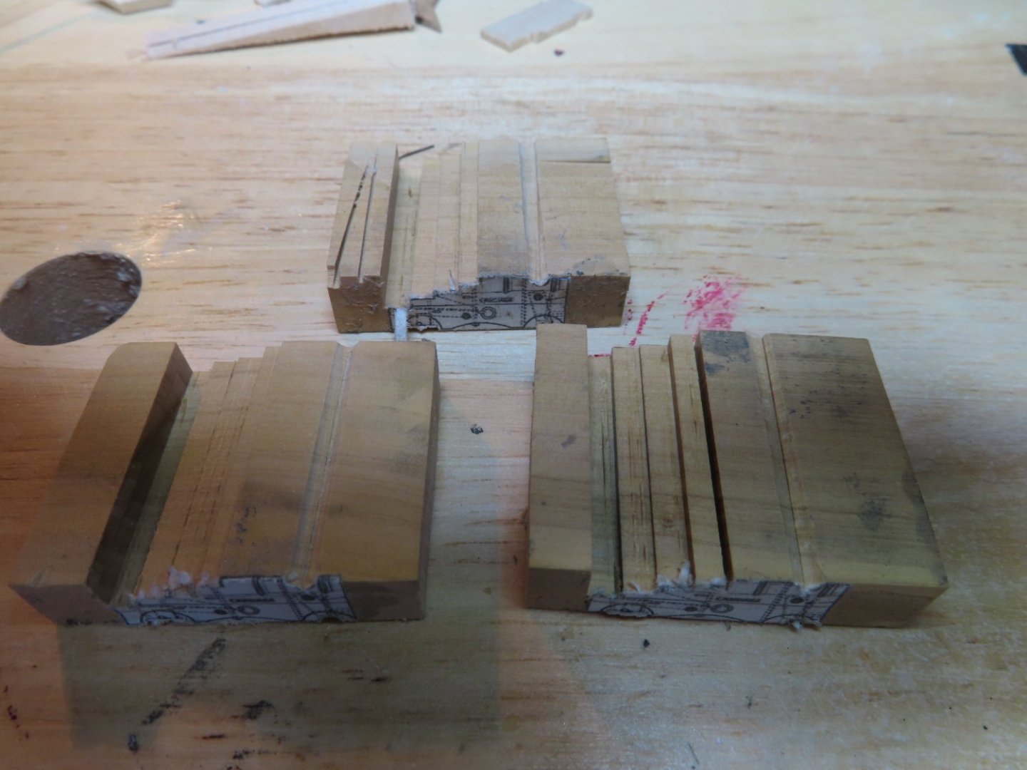

-
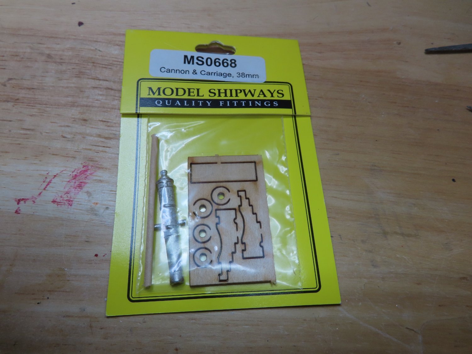
Gun Deck Fully Rigged Guns With trepidation, I have finally arrived at the gun deck to fabricate and install all of its armament, rigging, and structural deck elements. Like its furniture I fabricated previously, (but not installed yet), all of it will have to be scratch built, save for the gun barrels. There are 22 gun ports remaining waiting for their guns. Some years ago, I was far sighted enough to buy from a fellow Constitution builder, his excess Model Shipway cast metal guns he purchased from Model Expo for his build. I forget why they were available, but he sold them to me much cheaper than what I would have to pay for at Model Expo. I believe at the time when he bought these, Model Expo was selling them at a discount rate if they were bought in bulk. Today, Model Expo sells the gun and carriage package (MS 0668) singularly for $7.00/pkg. No bulk discounts. That’s $210.00 for all 30 guns, a tidy sum. The laser cut carriage kit pieces that came with the guns were useless to me as they did not match the US Navy plans (too short in height), and all you got were the two sides, a simplistic unrealistic bottom, four wheels and a dowel to make some bare unsupported axials. There was no front transom or breast (bumper) piece and forget about any hardware. Still, it’s cheaper than Syren Ship Mode Co.’s offerings. Their guns are of course much better quality (either black resin or turned brass) so obviously you pay even more for them. The carriage kits are better too and are sold separately, an additional cost should you want them. Luckily, Mr. Hunt’s practicum for the Rattlesnake, my previous build, had his followers scratch build the gun carriages, so I have some experience doing this.

-
USS Constitution by mtbediz - 1:76
JSGerson replied to mtbediz's topic in - Build logs for subjects built 1751 - 1800
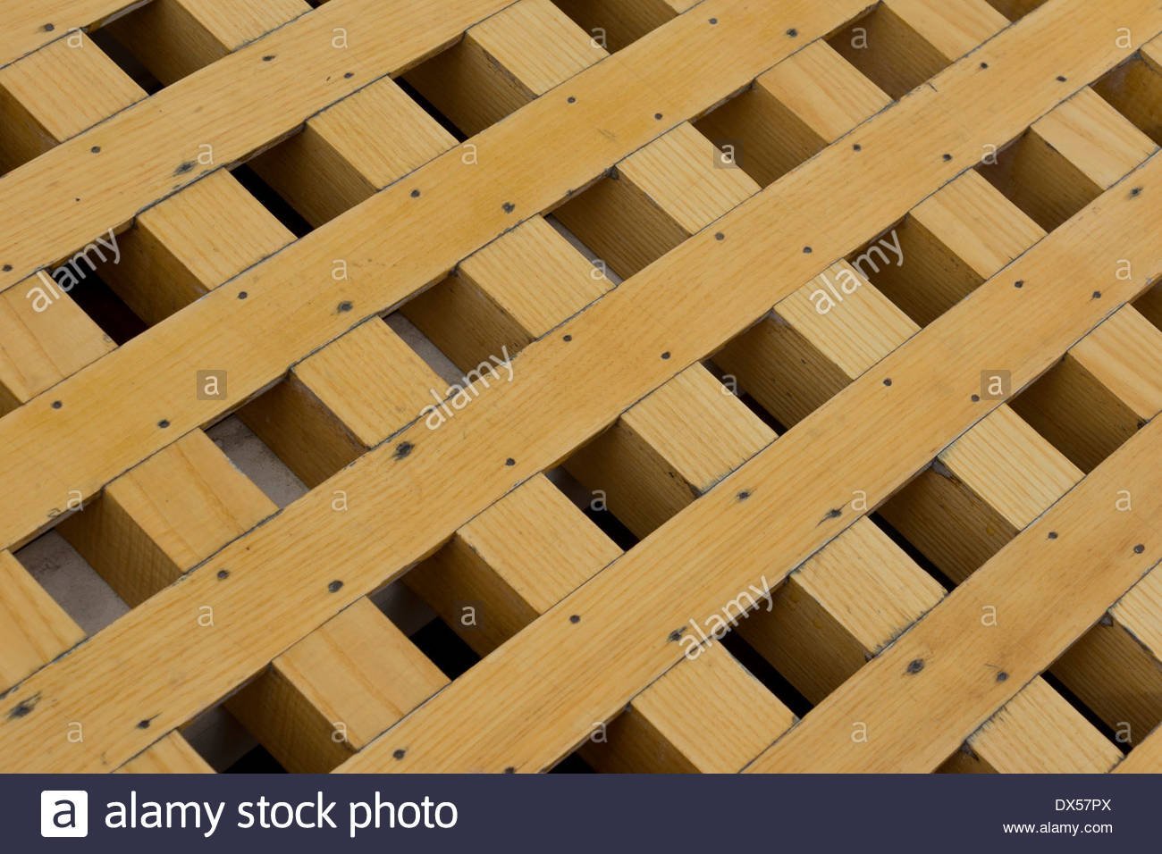
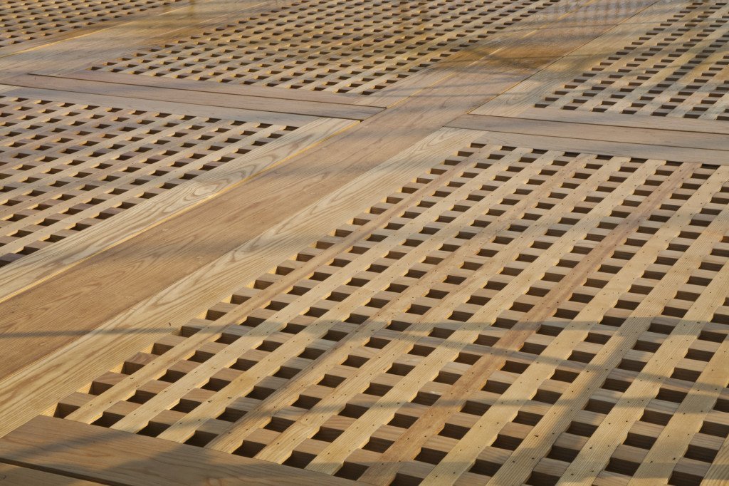
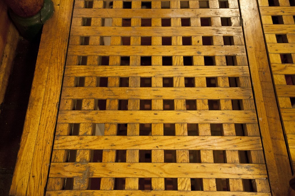
Beautifully done gratings. They look exactly like the real thing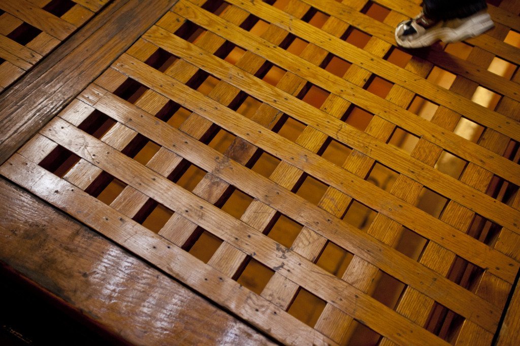
-
Like you. I did a lot of research and as you read my log, you will find that I rely a lot on the US Navy plans which you can still download for free from the US Constitution Museum. The collection of plans is not complete and range in dates from the 1800s to recent times. The MS kit is based on the 1927 restoration so if you follow the kit faithfully, it won't look exactly like it is today after the 2017 restoration, which what I'm making. Also I've built up an extensive library of images (approx. 4,000) so if you need a view or a "better" view of something, there is a good chance I may be able to help. I write my log in Word as well, but crop, group, and annotate images in PowerPoint. I group the final picture if there are multiple images, then "save as picture" as a png file. The text is simply copy and paste straight from Word into the online log. Mr. Hunt is an excellent builder but he has his quirks. I followed him fatefully for my first square rigger, the Rattlesnake and found that as I progressed into the practicum, he started to cut corners or did not address certain details. He stated that he is the first to admit that his way may or may not be the best way to do something. His practicums are like a diary written in real time, so if he makes a mistake, you will make the same mistake until he tells you oops, have to do this over later in his instructions. If something is not clear, check other builds to see how well they handled the problem. I am using him as a suggested guide for my Conny. As you read my log, I inform the reader when I'm deviating from the practicum and why. Two big deviations are I am adding the gun deck interior (scratch built) and have removed the topgallant rail (the one above the top rail) which was added in1927 but found to be not accurate to the ship so it was removed in the 1970s I think. The ship is a chameleon and changes its look over time, so if you haven't decided what era your model is representing, now is the time to choose. Jonathan