JSGerson
-
Posts
2,641 -
Joined
-
Last visited
Content Type
Profiles
Forums
Gallery
Events
Everything posted by JSGerson
-
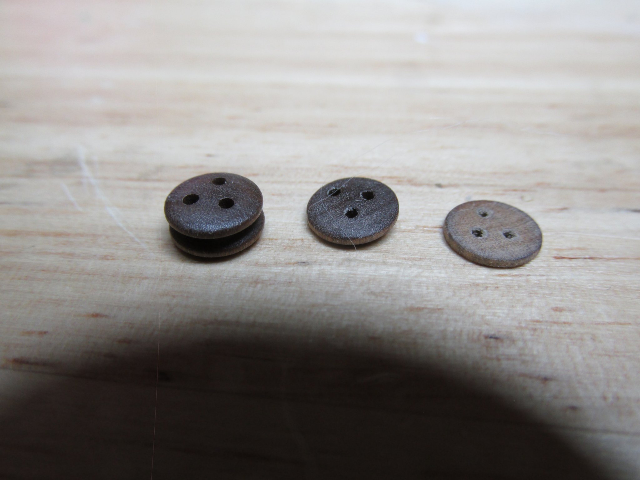
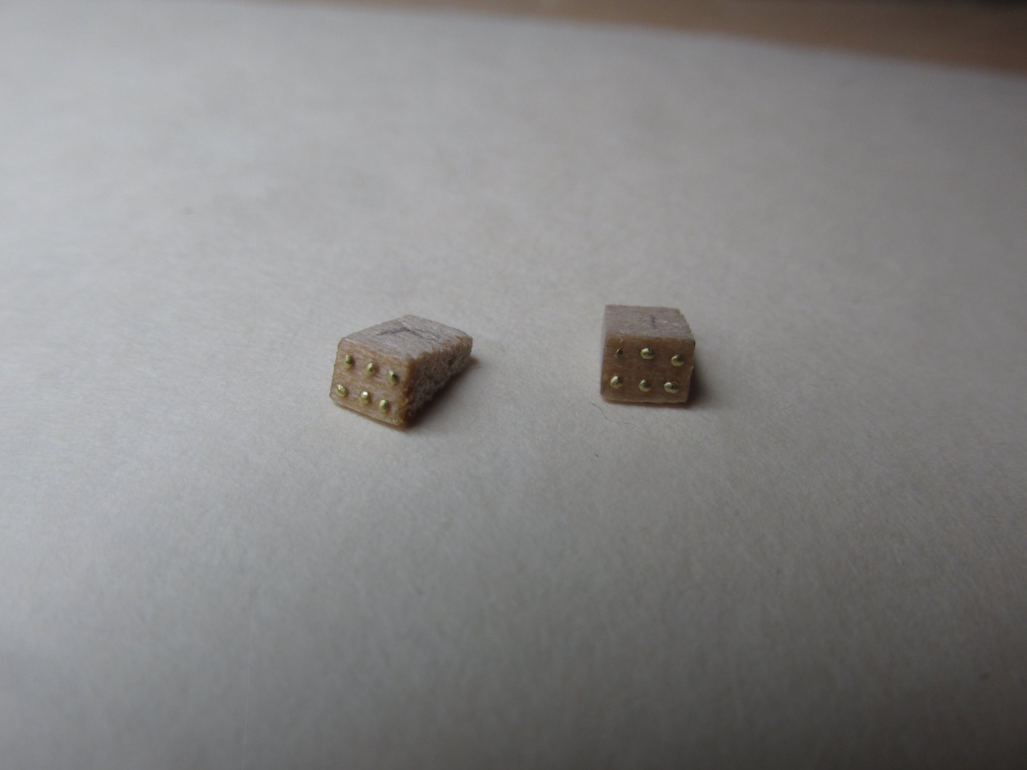
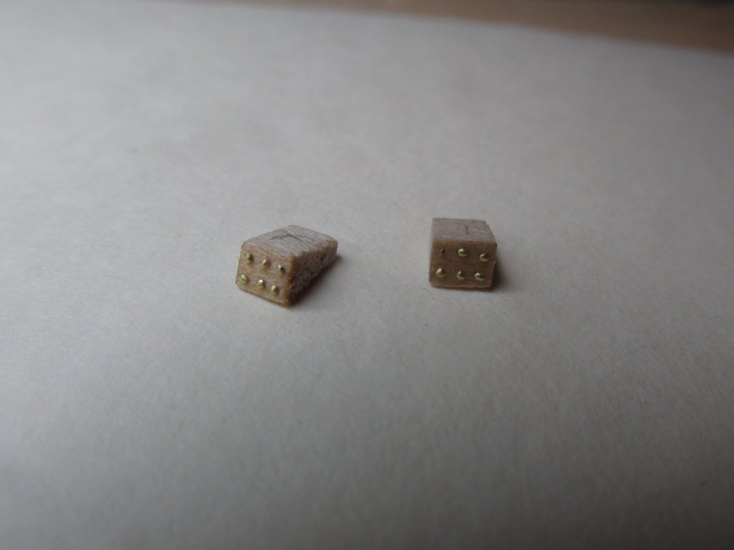
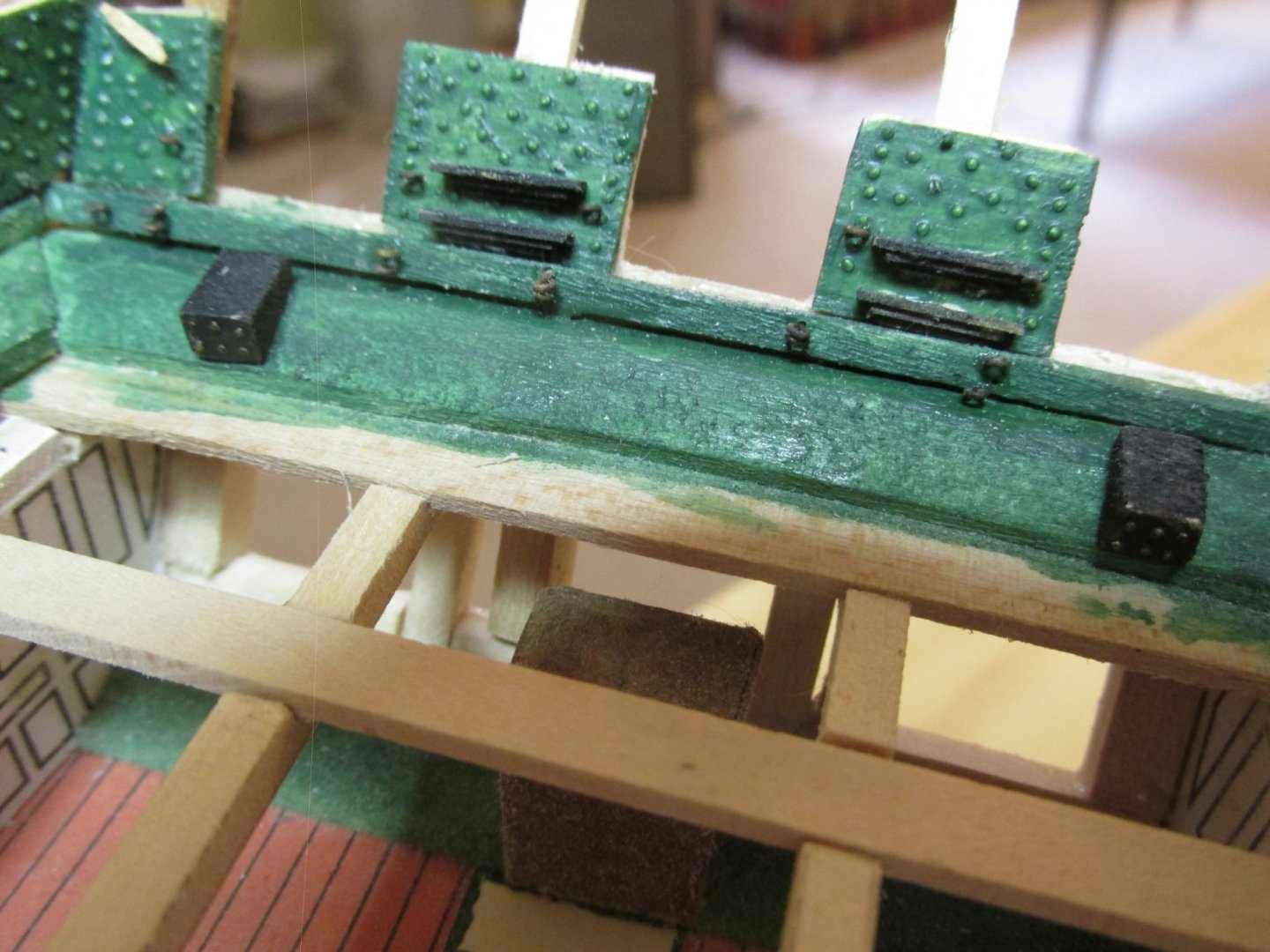
 You are right that a lot of modelers have gotten the representation of the fasteners of the copper plates wrong. They look like boiler plate rivets sticking out off the plates. As you can see from the image below, the plates are attached with copper nails which results in fine dimples on the plates. I am going to attempt to simulate the effect on my build using a stamp with fine needle points embedded in it. I managed to simulate the bolt heads on the bulwarks somewhat successfully (using 0.6 mm rivets I made using a fine punch) although I still feel the scale is off.
- 55 replies
-
- 4
-

-
- constitution
- model shipways
- (and 1 more)
-
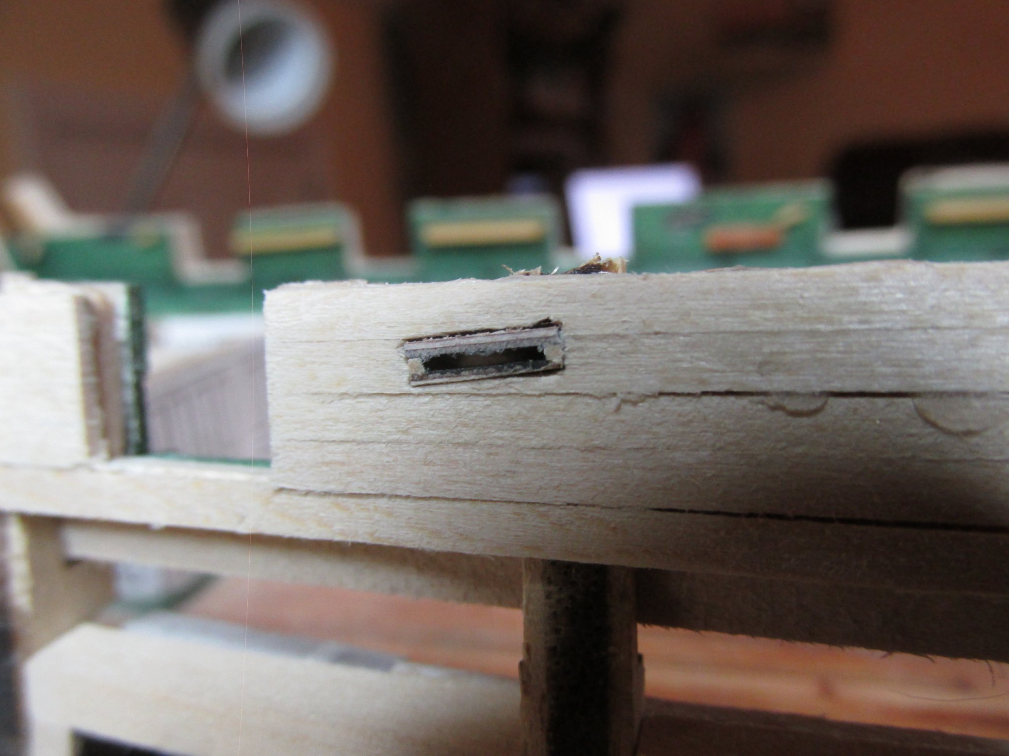
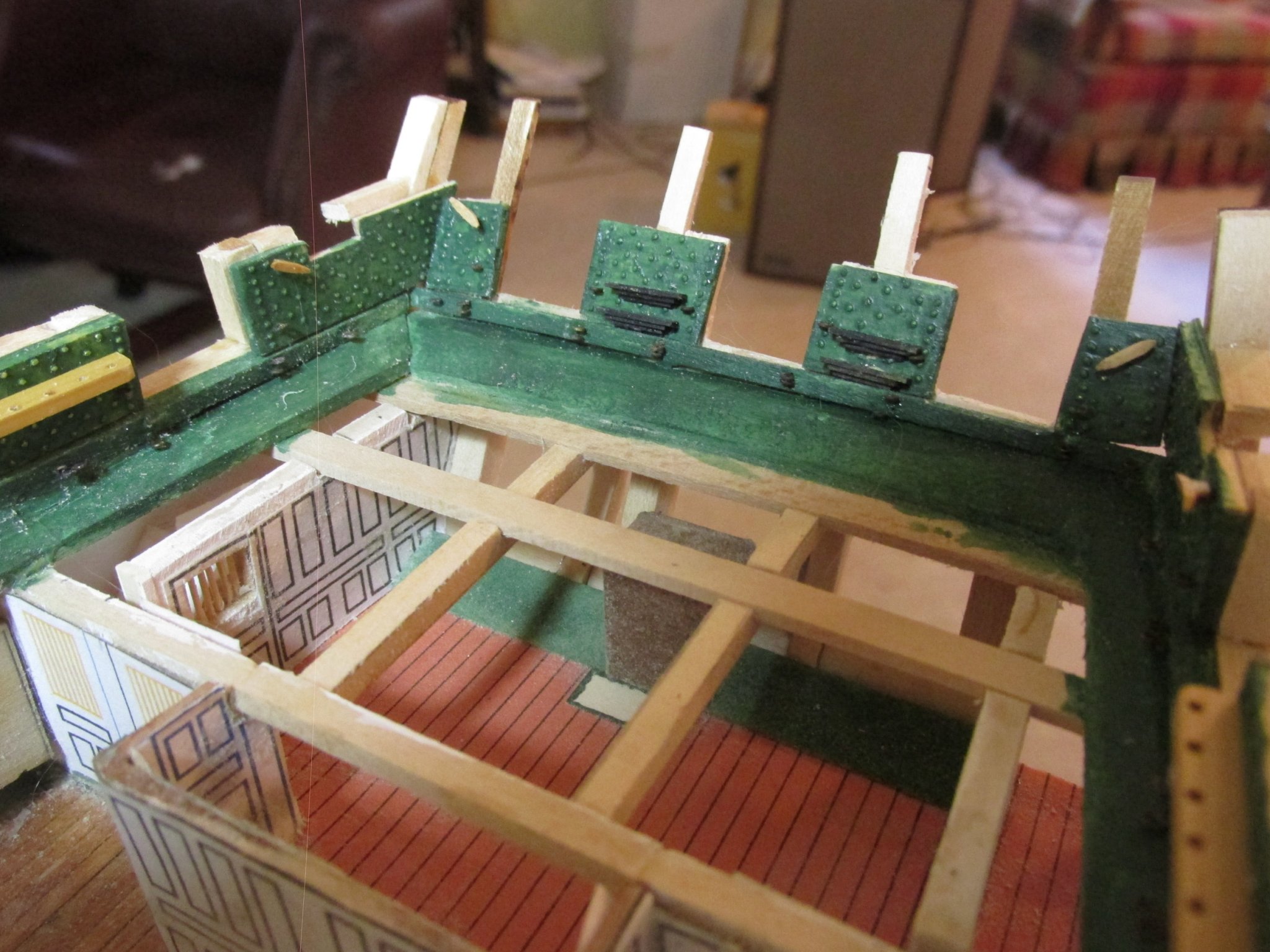
After detail filing each sheave and hull sheave openings so the sheaves would easily slide into place, they were glued in flush to the interior bulwark wall. On the hull side, they were filed flush.

-
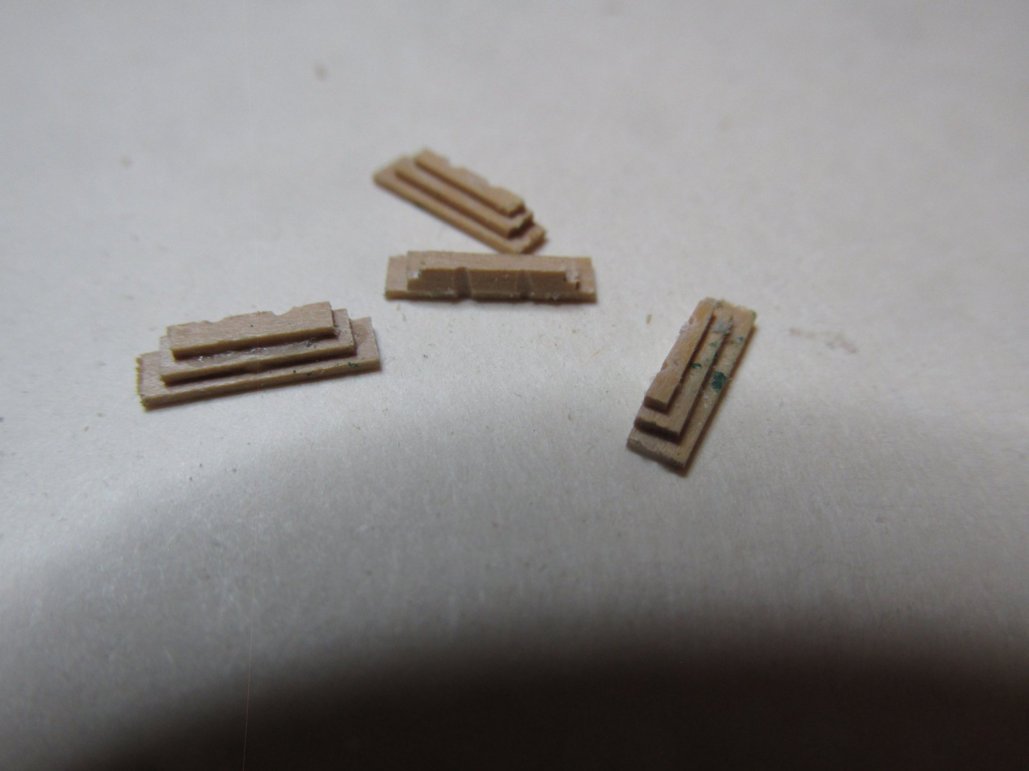
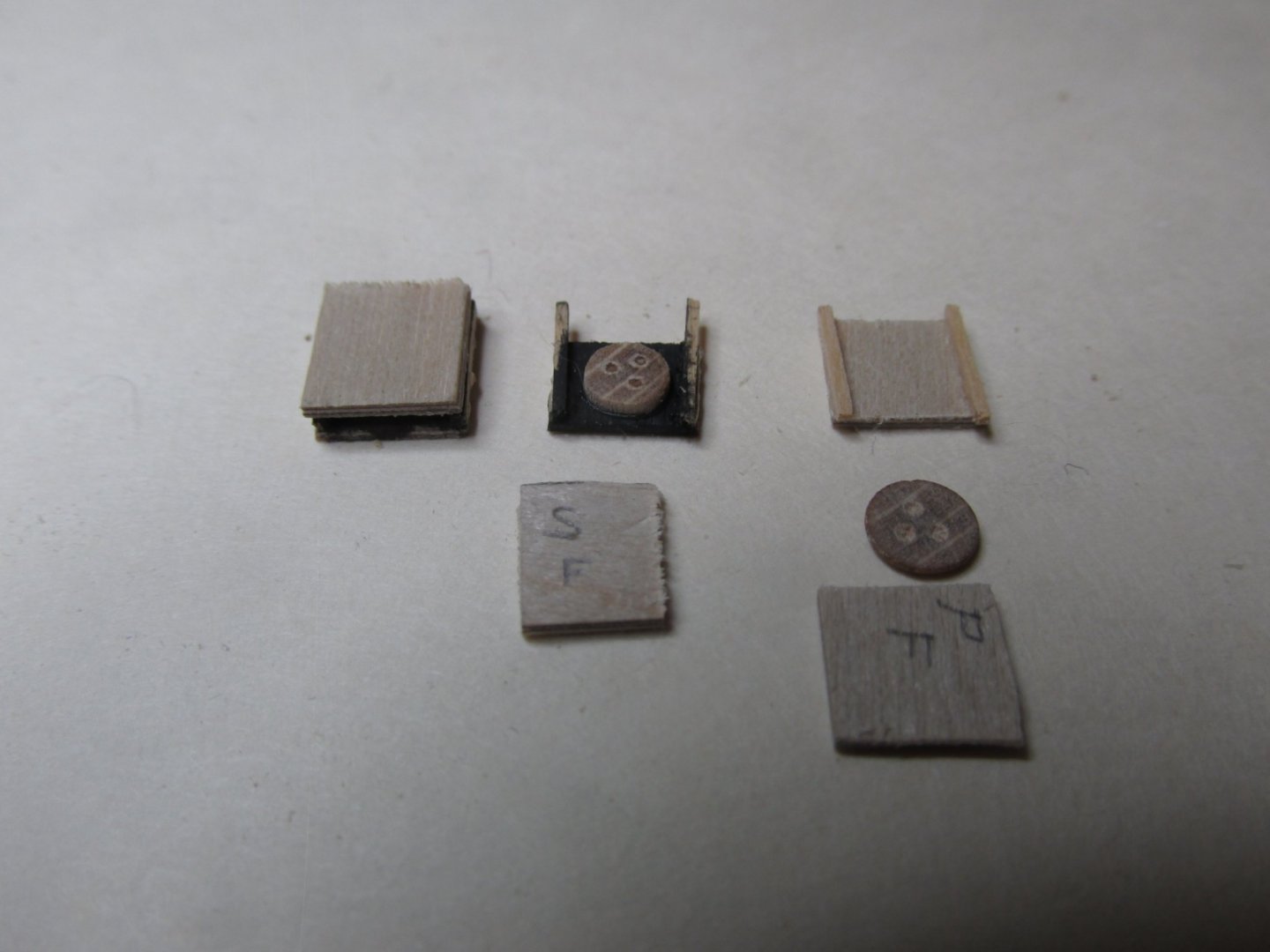
I had read on someone’s blog (I’m sorry I forgot where) about different uses for miscellaneous deadeyes. I had been given a bunch of odd fittings including some deadeyes from a model train hobbyist friend of mine who had no use for them, so I tried to see if I could use a couple. Using two 5mm Mantua deadeyes, I sliced them into halves and sanded both sides of each of the four slices till they were 1/32” thick. Then using 1/32” plywood, two rectangular pieces were cut for each of the four deadeye slices. These were to become a sandwich 3/32” thick. The plywood was used because it was convenient and only the edges would be visible, and these would be painted. Two pieces of 1/32” x 1/32” stock were used for the sides of each sheave completed the housing. The housing interior and the edge facing the deck were painted black, and the parts glued together. There was no effort made for the pulleys to rotate because they didn’t need to.

-
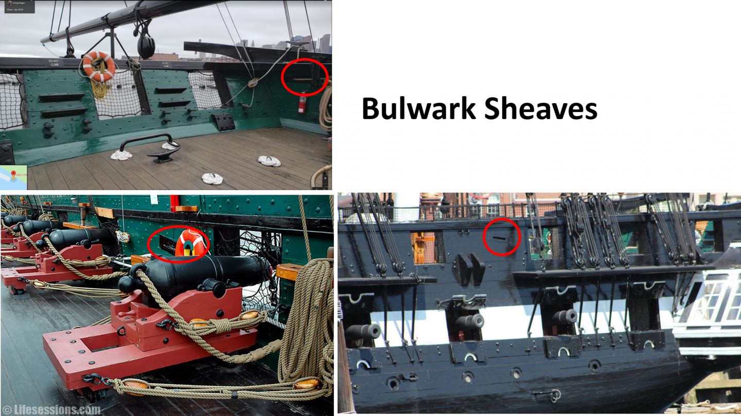
Continuing with the spar deck bulwarks, it was time to install the four bulwark sheaves at the aft end of the model.
-
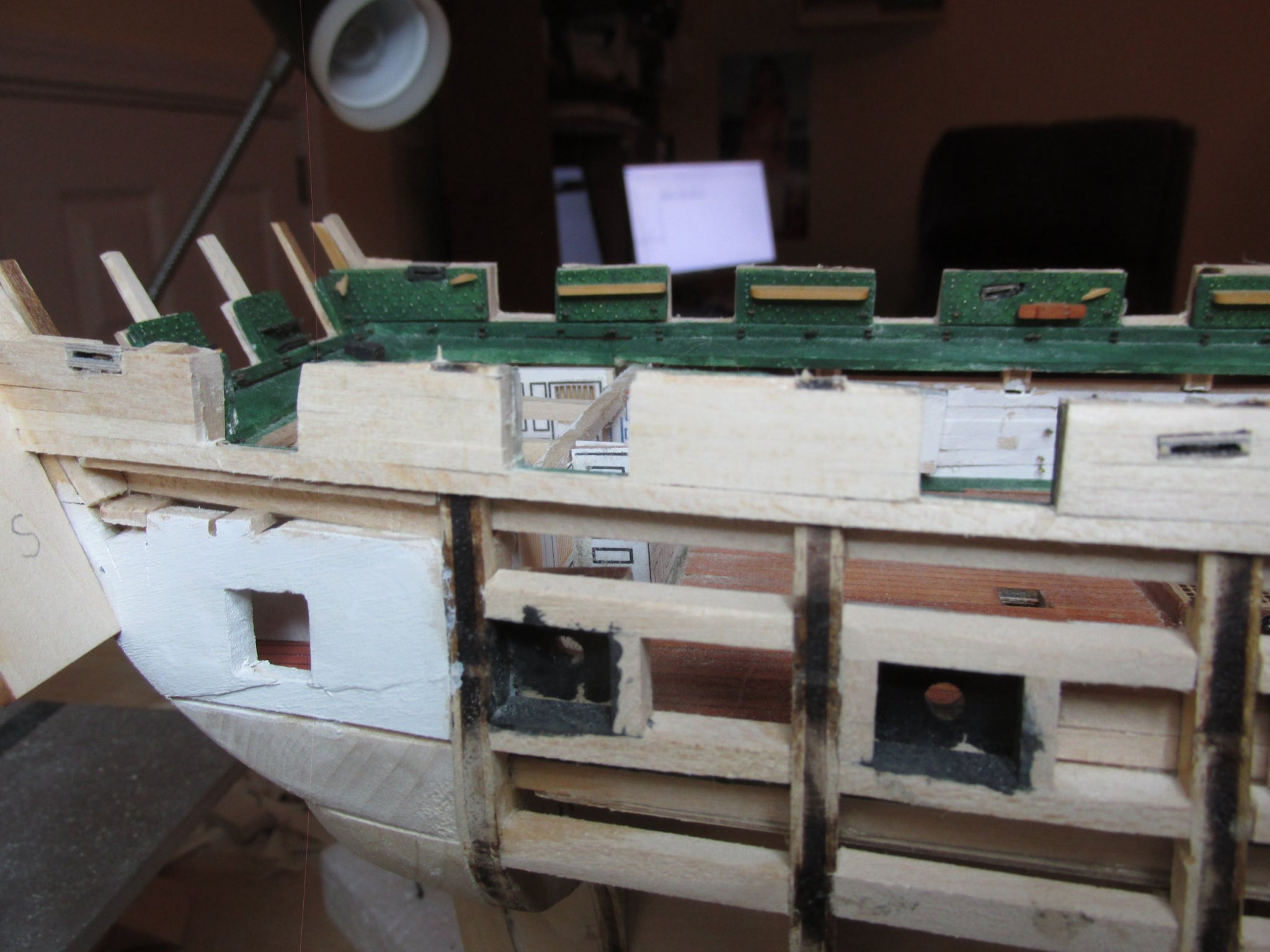
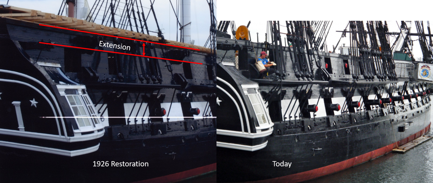
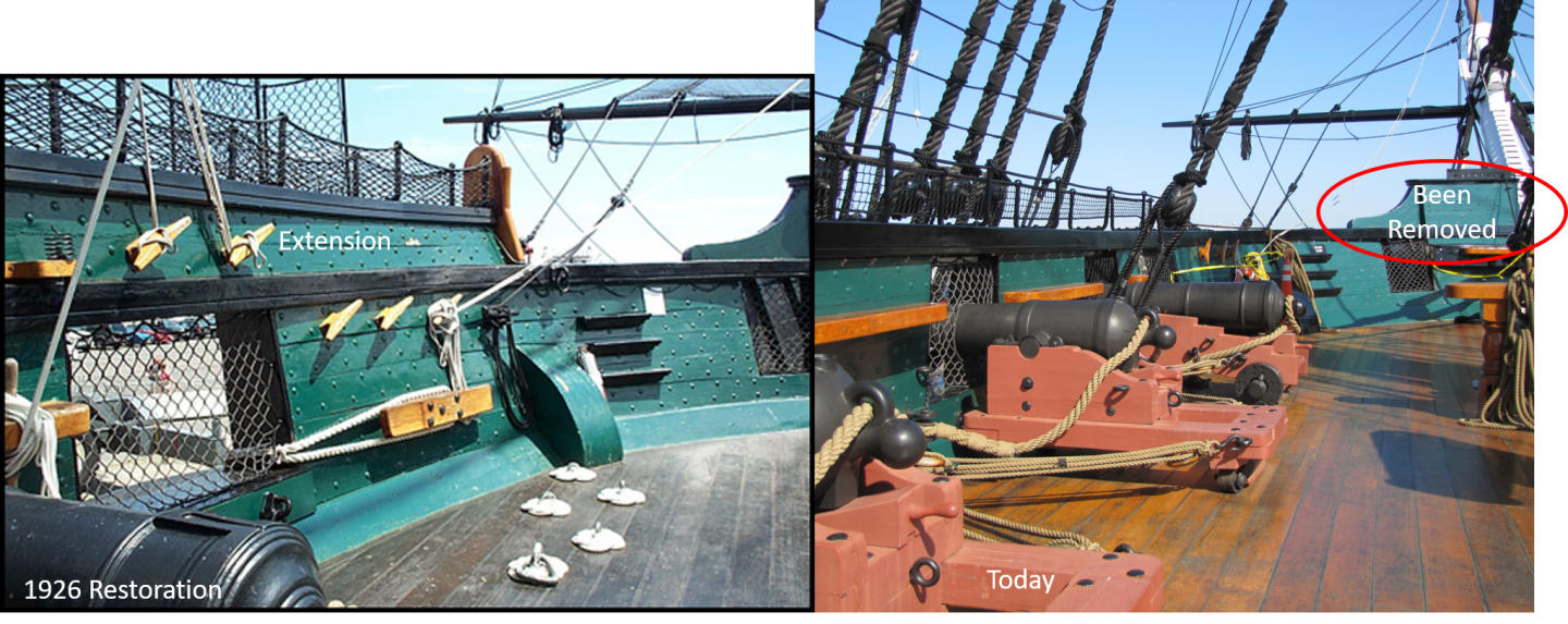
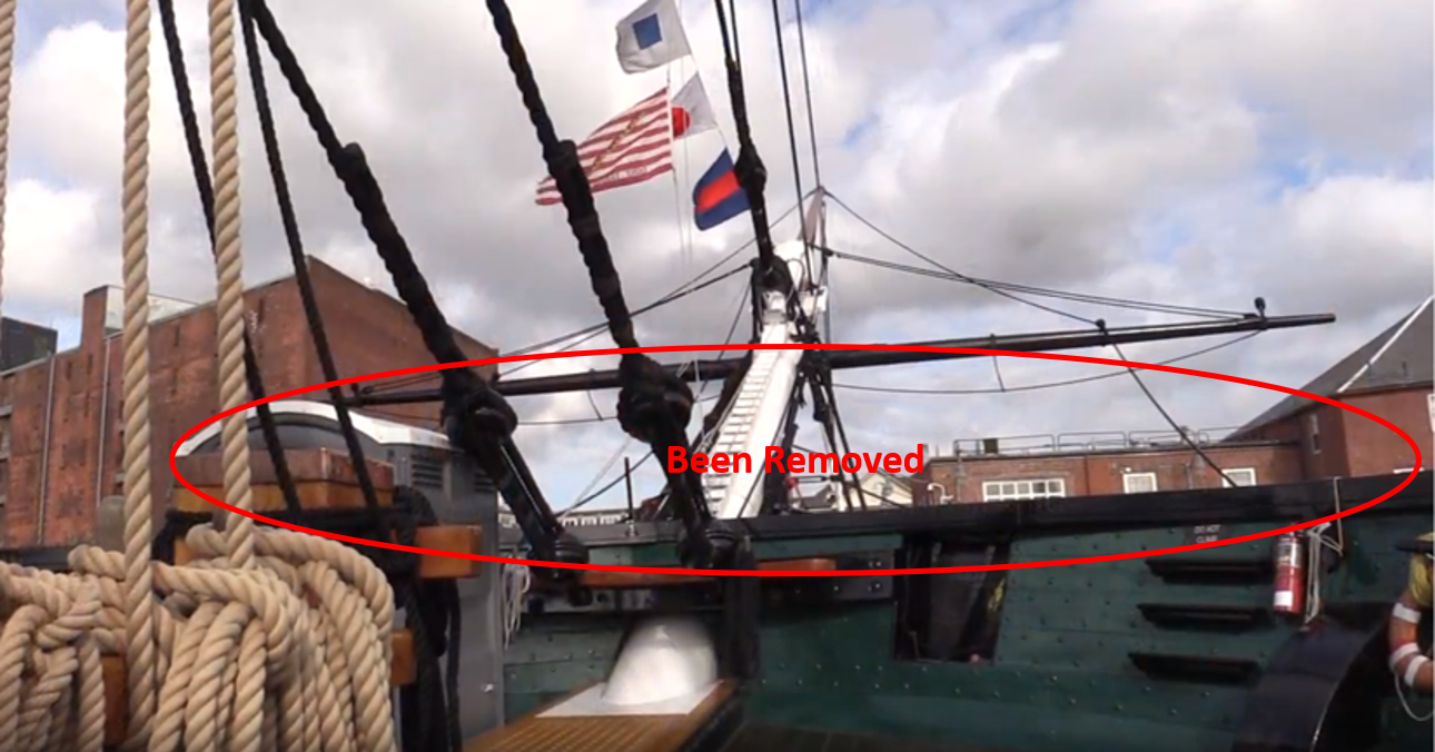
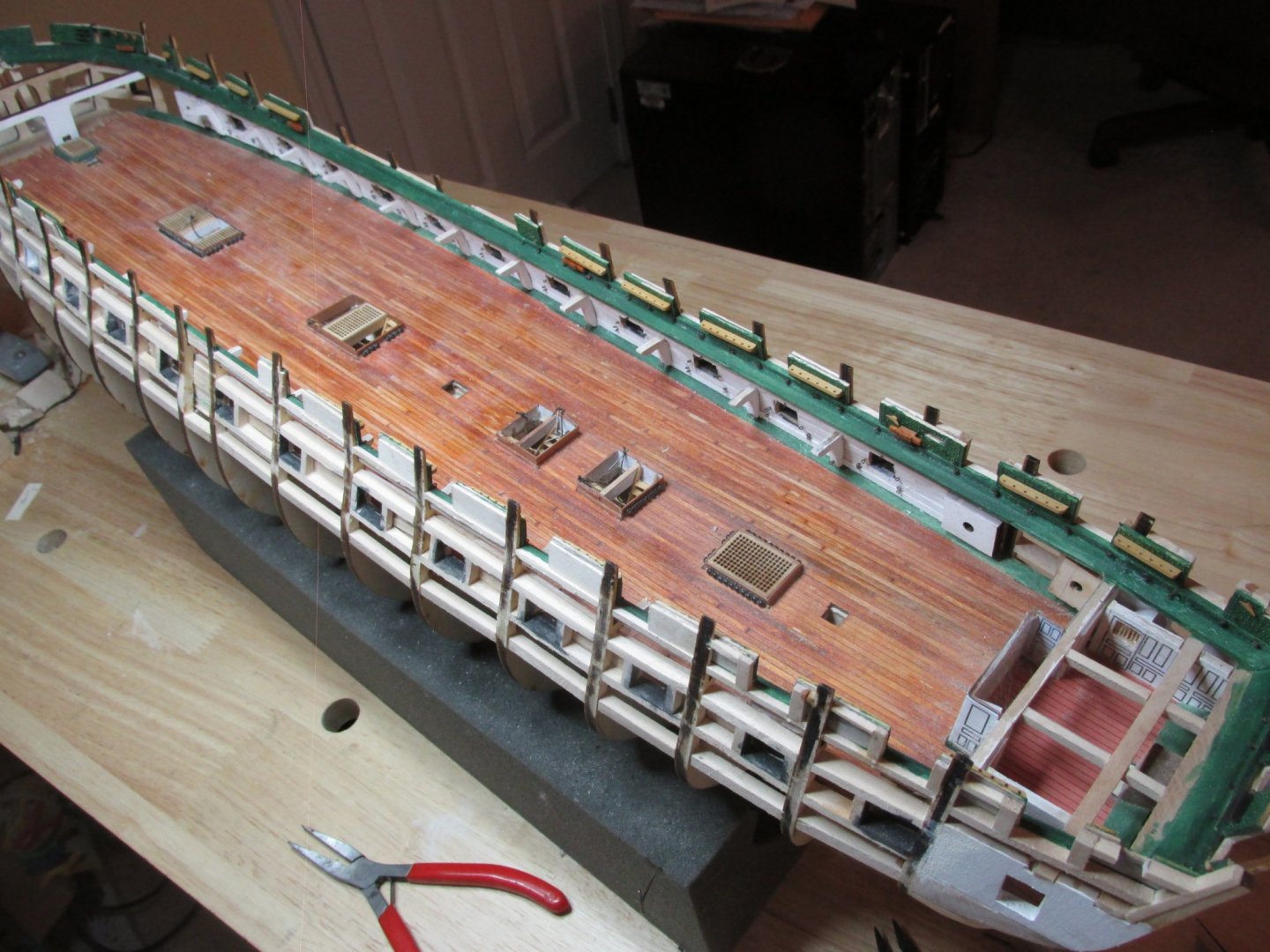
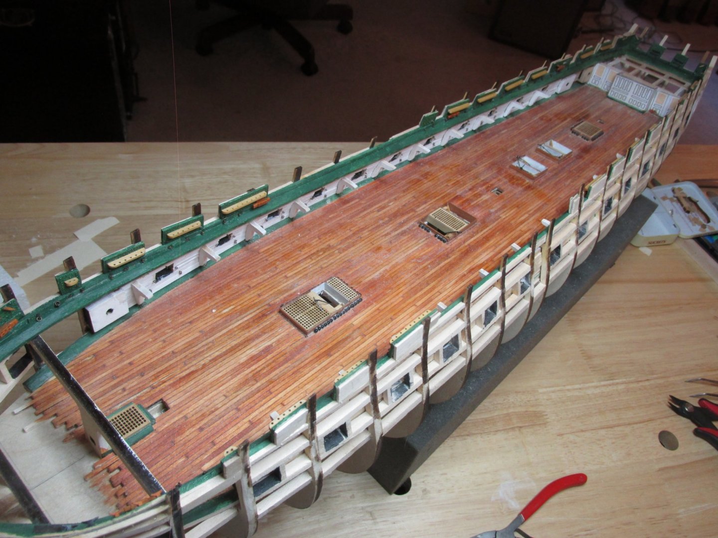
It’s been about a month since my last post; I have had some highs and lows in that time. I’m still struggling with my left eye although I got the remainder of the stiches removed today– four in total. It’s slowly improving but up till today, I was just using my right eye. Now there is a marked improvement. We’ll “see” what the Doc says in two weeks. I made the effort to go to the NRG Conference in New Bedford MA (Oct 23-27), where I met old friends and generally had a good time despite some travel headaches, but that’s another story. However, on Nov 2, my Mom died at 101yrs. It was not unexpected but still it was a shock when it happened. My time was spent with my family and doing the things that needed to be done when there is a death in the family. Weeks later, things are slowly getting back to normal, but there are things that still need to be done, Thanksgiving is coming, and I’ll be with my sister for the holiday week. On the bright side I was able to get my mind on an even keel as it were, by working on the model. It puts my mind at ease. I was able plank the remainder of the hull between the side spar deck gun ports. You may also notice that I have trimmed the bulkhead extensions that stick up above where the cap rail will go. They extended to support the Topgallant Rail. This was the “Cap Rail” of the added hull and bulwarks on top of the actual Cap Rail. This extension was added in 1926 and subsequently removed in later restorations. Since my model is trying to reflect what the ship looks like today, it will not be built as shown in the kit plans which is based on the 1926 restoration.


-
My left eye still is not up to par although I’ve improved a bit. My eyesight went from 20-400 to 20-200. But the call of the shipyard was strong so I’m at it again albeit proceeding with caution. I still have 4 stitches to be removed after I get back from NRG Conference. I’ve managed to install the planksheer without too much effort and added the first transom extensions for the quarter galleys’


-
Thanks Tom. So far, my eye doesn't itch and I do use three kinds of eye drops 4 times a day. Right now its like looking through a very dirty window. I'll be back at the doctor office in 4 days.
-
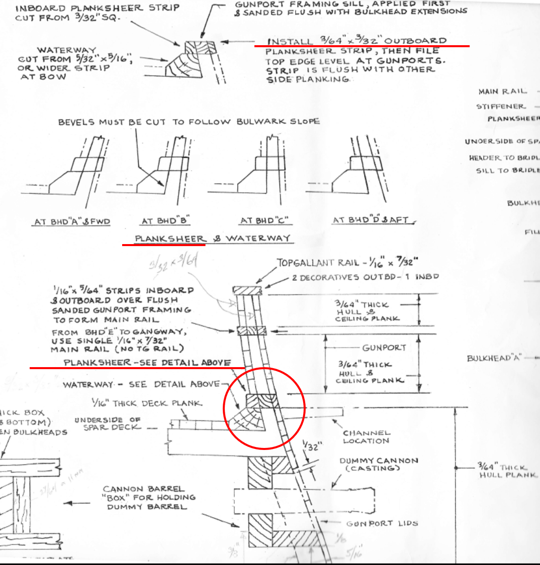
Well I wasn’t “shown otherwise” but a comment made by another builder made me realize I interpreted Mr. Hunt’s terminology wrong. When he stated “the planksheer on the outside to be thicker than the other planking” I interpreted the term “thicker” to mean thickness of the plank, expecting the planksheer to be proud of the hull like the wale. He was using the term to mean the width of the plank which, after I realized that, was definitely shown on the plans as wider. Still no actual work on the model as my left eye still does not see well after cataract surgery which it definitely needed. A day after the surgery (Oct 1) I could barely make out the big letter “E” on the eye chart. My cornea clouded up due to the non-routine procedure that was required. It might be a month before the eye settles down.
-
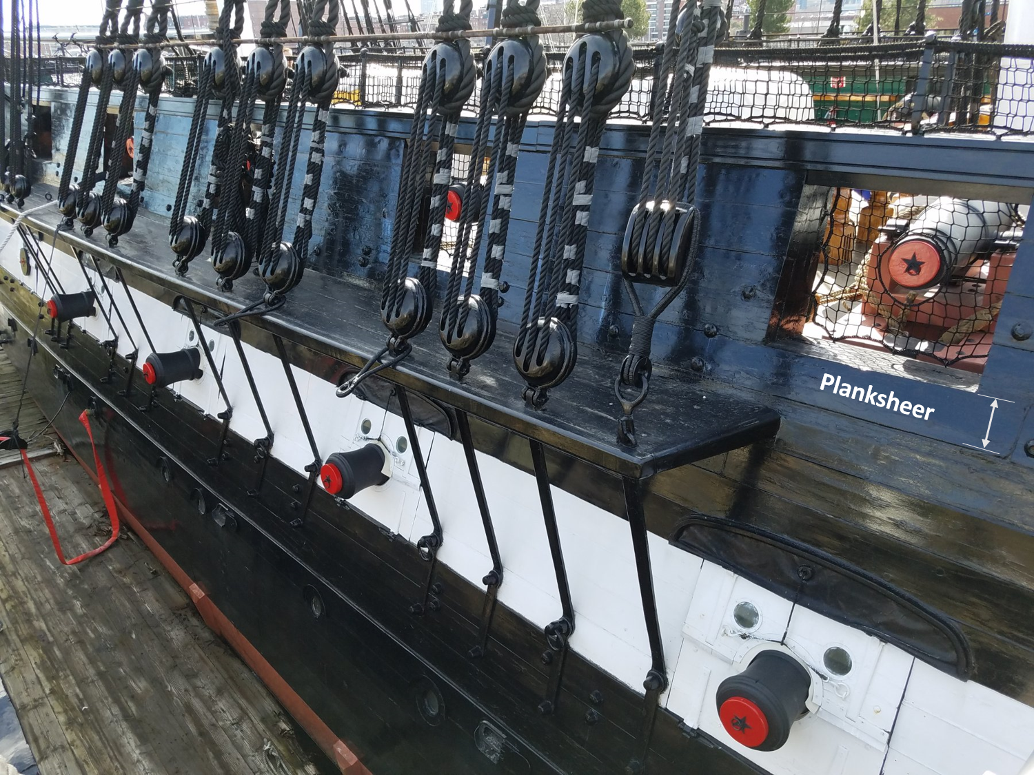
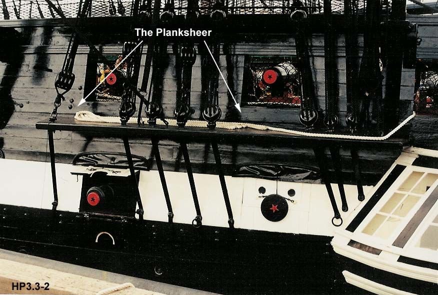
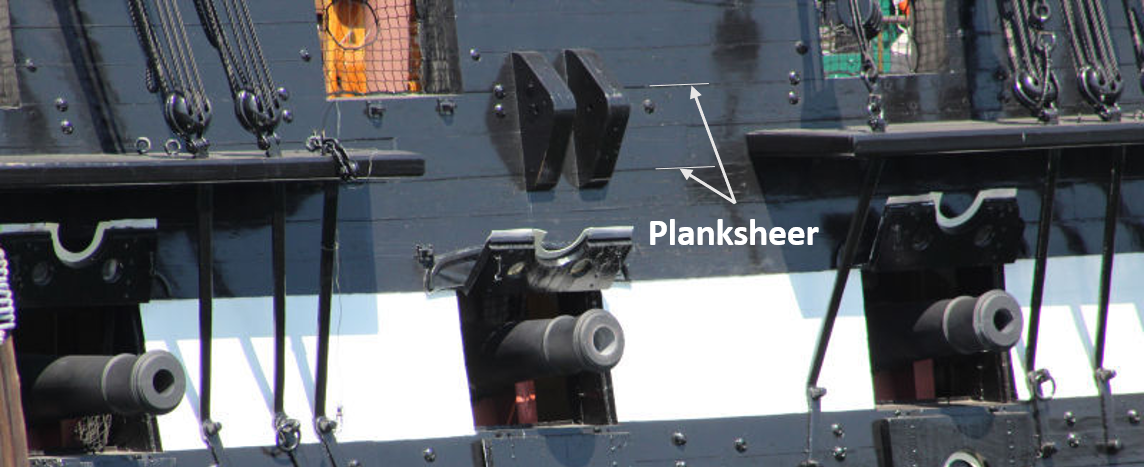
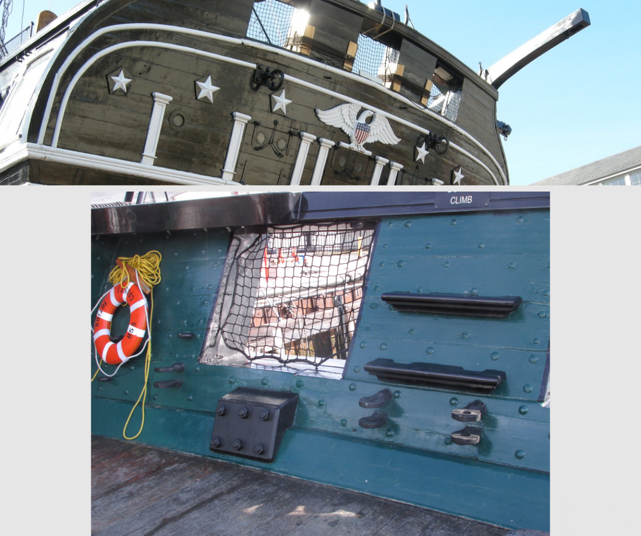
Planksheer I thought it might be a good time to finish up the gun ports. This meant that I would now have to plank the hull from the gun deck to the cap rail, so I went back to the Robert Hunt practicum for some guidance. He started with the planksheer. First thing he stated was that the planksheer was “slightly thicker than the planks above” the planksheer. He also stated “…if you look at sheet 3 of your plans, Hull Planking Layout, it also clearly shows the planksheer on the outside to be thicker than the other planking.” He provided a photograph to illustrated it. Now I may need cataract surgery, but I’m not blind…yet. For the life of me, I could not find on the plans where the planksheer is shown or indicated as being thicker. The image he provided (HP3.3-2), as near as I could determine, did not provide proof of the extra thickness at least to me. I even checked all my reference images and rechecked the images online. They all confirmed my observations, the planksheer is no thicker than the other planks. Shown below is the referenced plan, Mr. Hunt’s photo, and my two photos.


-
Nice clean look
-
One of the odds and ends I mentioned earlier are the two “backing plates” for the “towing bridle ring bolts” located just below the two outer port openings in the transom. The other item I decided to wait on are the four hull sheaves. Those will be done once the hull planking installed around the gun ports. As a matter of note, I had planned to have cataract surgery this coming January, but my left eye got bad very quickly, and by quickly, changing daily. So, I will be having the surgery for the left eye Oct 1 and the other eye hopefully two weeks later. This of course will slow me down juusssst a bit (not that you will notice from my normal lightning pace) in my build.
-
Just discovered your build and it looks great. I too am using Mr. Hunt's practicum, as it is a valuable resource. I could not have built my first square rigged ship, Rattlesnake without it. Just be aware that he is not infallible, he makes mistakes, and he does simplify some of the detail which may or may not be to your liking. In my Connie build, I am using his practicum as a guide and not the bible as I did with the Rattlesnake. That's partially because I am adding as much detail as I can to the gun deck which he, and the Shipway instructions covered up with a fully planked spar deck. I use a lot of reference photos of the actual ship to guide me and I assume you will too. The Shipway kit is based on the 1926 restoration which NOT how the ship looks today. So make sure when you are looking at a photo, it is reflecting the proper time frame of your model. A good example of this is the topgallant rail. It was installed in 1926 but has been subsequently removed. I look forward to seeing future installments of your build log. Jon
-
Well for the most part, the bulwarks are done…finally. They bulwark panels were glued into place and the eyebolts were installed. There still are some odds and ends that still needed to be fabricated and installed, but the most tedious part is completed.

-
Once that was completed, the transom bulwark panels were constructed, and the pseudo bolt heads were added. At this point, all the bulwark panels were painted green like those forward. Finally, I fabricated two small wooden transom cleats and four transom bulwark steps. Once I painted all the bulwark panels green and the transom steps black, the remaining cleats and steps were installed. This left the cannonade rigging eyebolts to be installed. Those eyebolts which I could install onto the bulwark panels was done, which left 66 or so odd eyebolts need to be stalled just below the gun port openings on the planks just above the waterways, plus about 14 double eyebots.


-
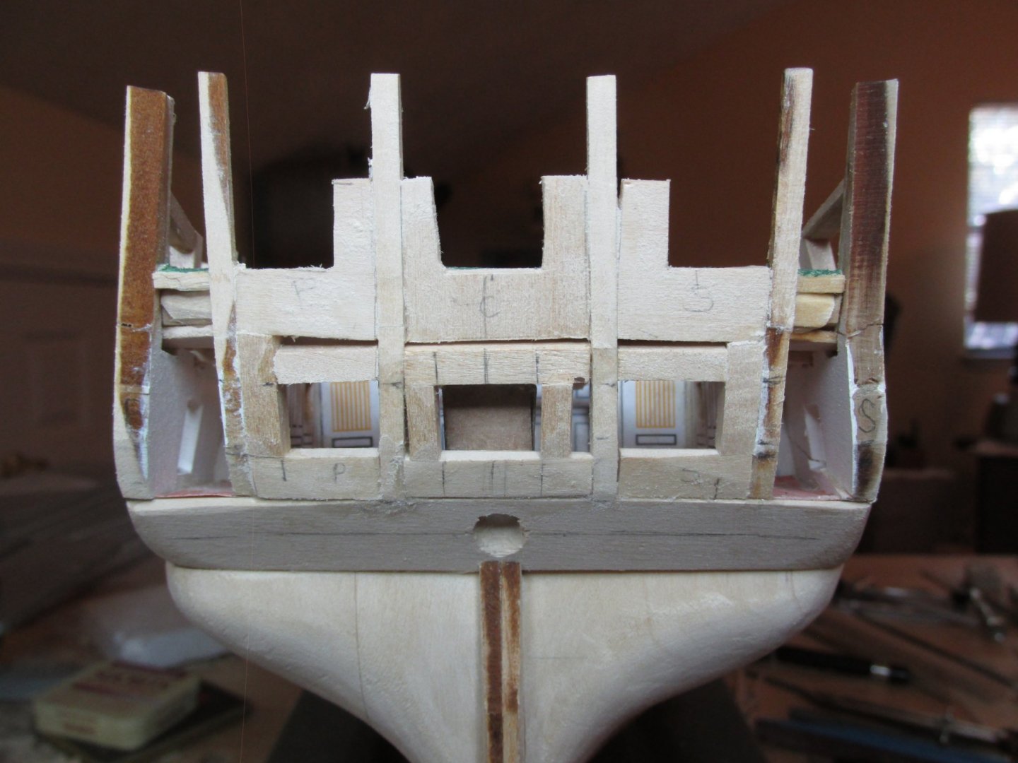
After a few personal activities including another trip to Florida with my sister to visit Mom for two weeks, the shipyard finally opened again. I swear, my Mom saves all the “honey do’s” to happen when we arrive. We weren’t inside her condo for more than 5 minutes when the land line phone went dead as well as the internet (both supplied by AT&T). {Note: because she is 101, we wanted to ensure that we could communicate with her should the power go out. The landline is the simple analog type which supplies its own power. Cell phones need power to recharge. So, the irony is obvious.] That took a couple of days to fix as they had to dig up the line and replace it. Other things like simply changing a fluorescent tube in the kitchen got more complicated when I discovered that I had to replace the ballast unit as well. Just a typical trip. Then there was the worry about her while Hurricane Dorian park over the Bahamas. The initial forecast had the storm track going right over her home. Luckily that didn’t happen; she didn’t even lose power. Back to the shipyard, I wanted to finally add the bolt heads to the transom bulwarks. This required that I first build the framework for the stern windows and ports for the gun and spar decks. This took a couple of tries as it required critical precise measurements. It may not look precise, but the ports and windows are measured from the center line. All the structural elements will be covered by the bulwarks and planking.
-
All sound reasons, not that you need any when picking a model. If it's something you like, build it. I've thought about maybe a Lobster boat or a tug boat in the far distant future when my USS Constitution is completed. As for a display case build log, that would be of general interest to many, A number of builders include this as part of the main build log. I did with mine even though most of it was purchased.
- 57 replies
-
- 1
-
-
- rattlesnake
- model shipways
- (and 1 more)
-
A nice change of pace. Any particular reason for the PT choice? Are you going to make your display case or go the route I took, buying the case and table? My choice was easy, I have no woodworking tools (hand or power), save for my modeling tools, and I have absolutely no experience in making furniture.
-
It took me 7 years to build the Rattlesnake. I didn't think anyone would take longer to build this model than me, but you did at 8 years and it was well worth the wait. Congratulations!! Since you have invested so much time in creating this beauty, how are you going to display and protect her? And, are you going to take a breather?...build another model?...or what? If, and when you plan your next project. I look forward to your next build log. Well Done!! Jon
- 57 replies
-
- 1
-
-
- rattlesnake
- model shipways
- (and 1 more)
-
Thanks for the complements albeit a bit undeserved. To paraphrase an old saying, I'm standing on the shoulders of some might great builders. As for video recording, I build so slow that by the time I finish, today's video type, standard, method, etc. would be obsolete and YouTube would probable go the way of MySpace 8-). I've 2 1/2 years so far into this project and I'm 72 years of age. It's a race to see who finishes first!!!
-
First off, let me give ArthurN and mtdoramike kudos for completing their versions of the Conny. I hope to join those fellow builders who have accomplished that feat no matter what they think of their skills. A lot of people start a model, and never finish. This is only my second wooden square-rigged ship model so hopefully I haven’t bitten off more than I can chew. The MS model presently being sold is based on the 1926 restoration. That restoration has come under some criticism for some historical inaccuracies like the replicated cannons and the top gallant bulwark extensions. I am, for the most part, basing my build on the last restoration started in 2015 which is continuing to bring the ship back closer to its 1812 configuration. In addition, I decided to add detail to the gun deck as well. This has resulted in a large amount of scratch building, something I learned constructing the Rattlesnake following Robert Hunt’s practicum. This time I’m using Mr. Hunt’s USS Constitution practicum as a guide, not an absolute “how to” as before. I’m using a lot of other builder’s build logs as a guide as well. I also purchased the Mamoli plans from a fellow builder to be used as a cross reference and I also have numerous reference books on the Conny. From what I can tell and based on my limited experience, very few people follow kit instructions completely. Like you mtdoramike, my model also has wood from the actual ship which I was able to purchase mail order through the gift shop back in 2016. I got what I got; I had no choice in size or shape. I would have thought there would be a whole new supply during this last restoration, however, I have not seen any for sale lately. I’ve already incorporated some of that wood in the keel. Per your suggestions, I’ll try and incorporate more as the build progresses.
-
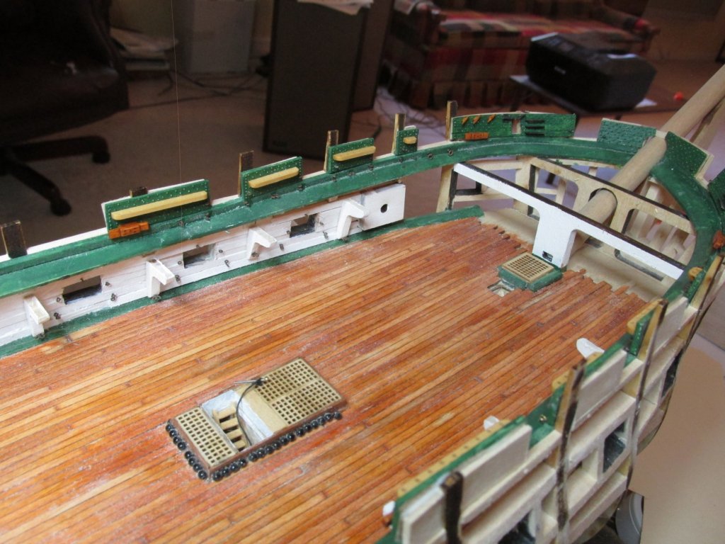
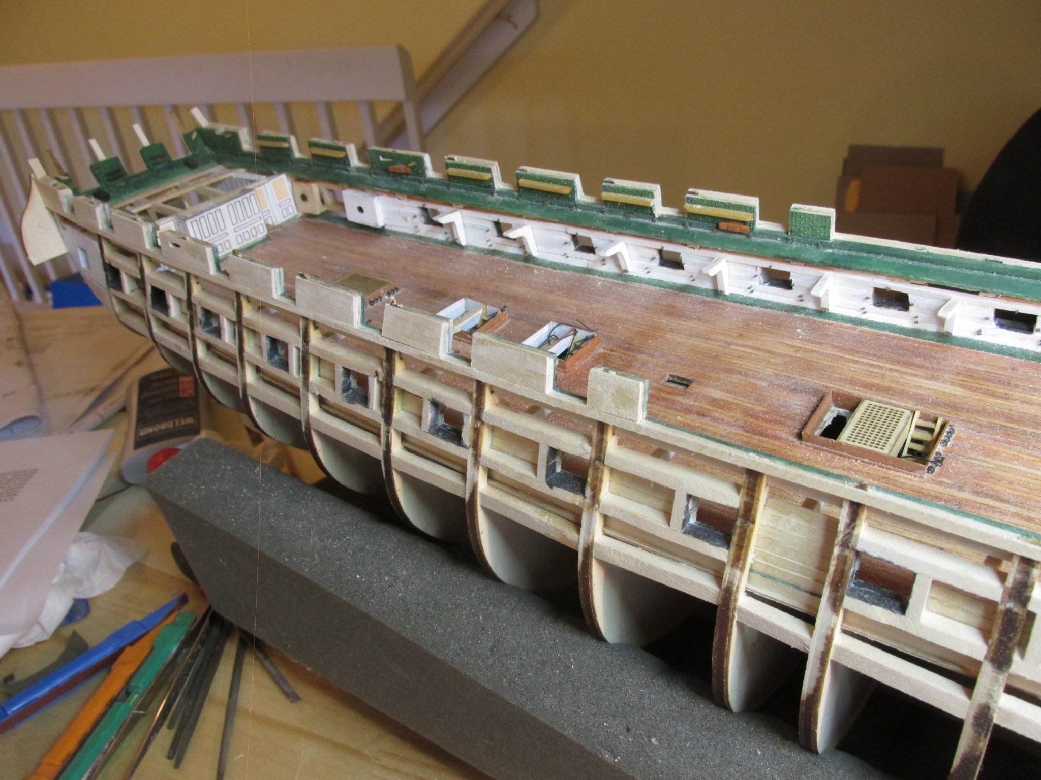
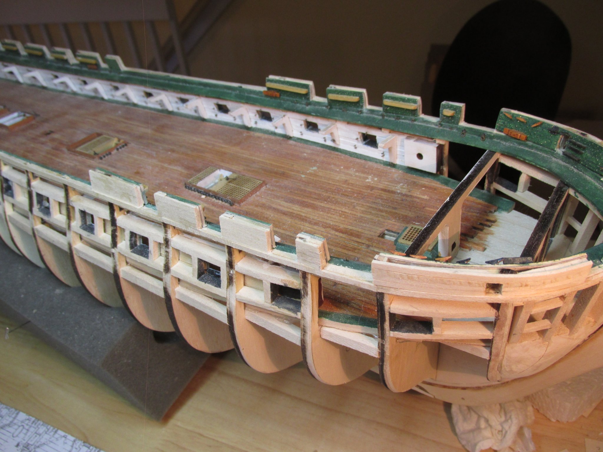
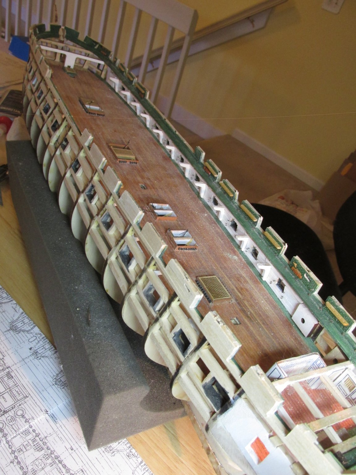
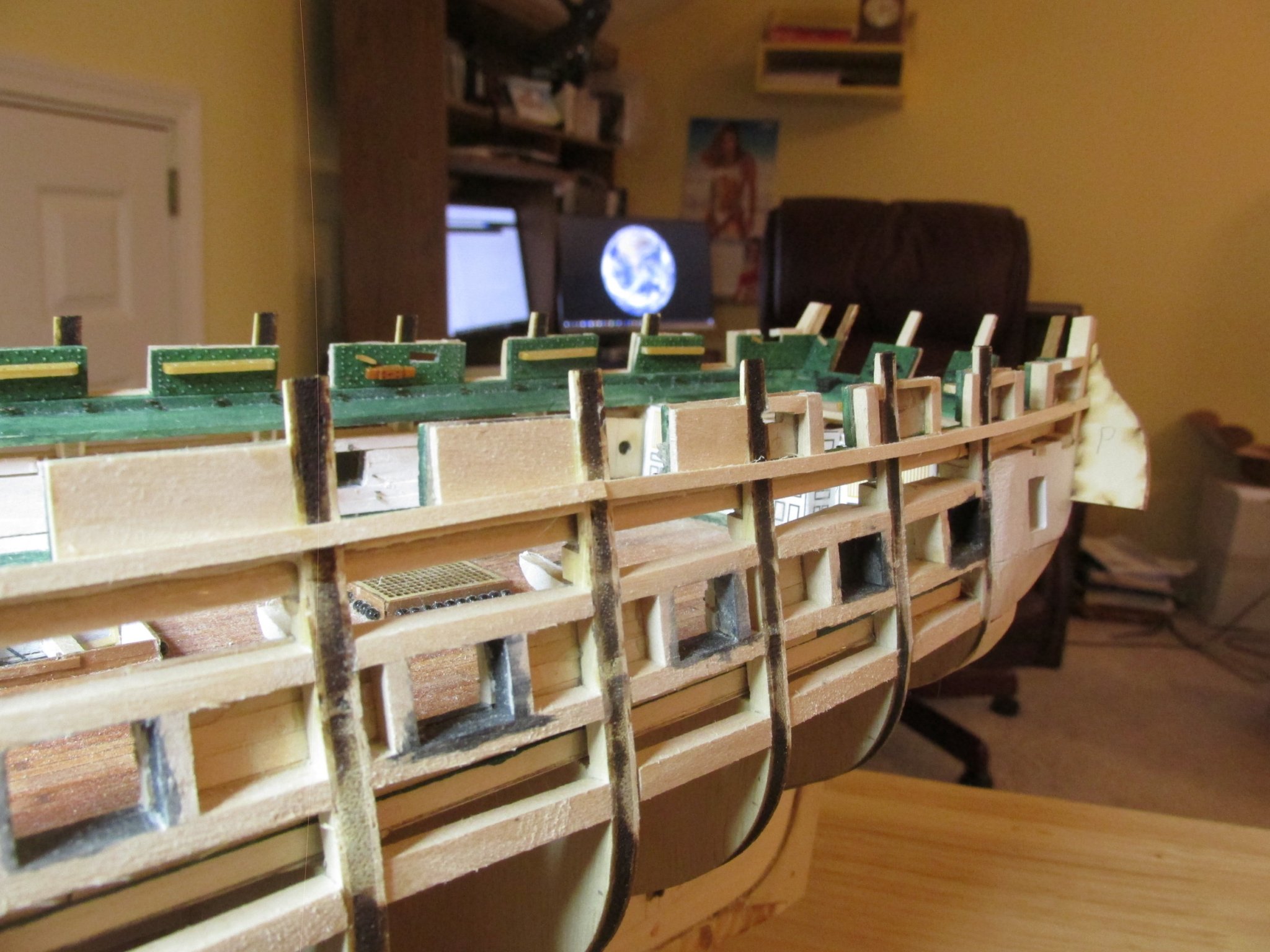
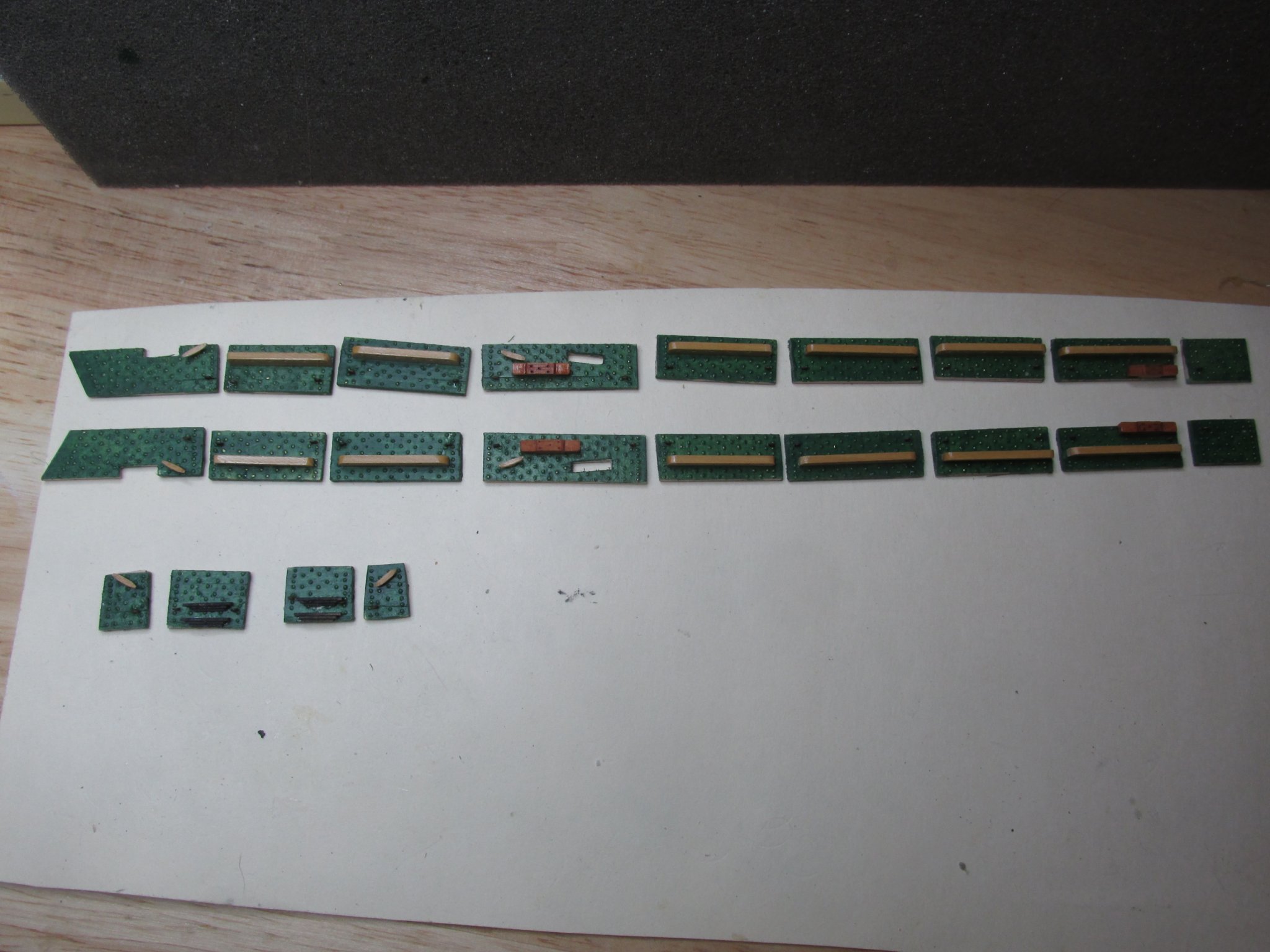
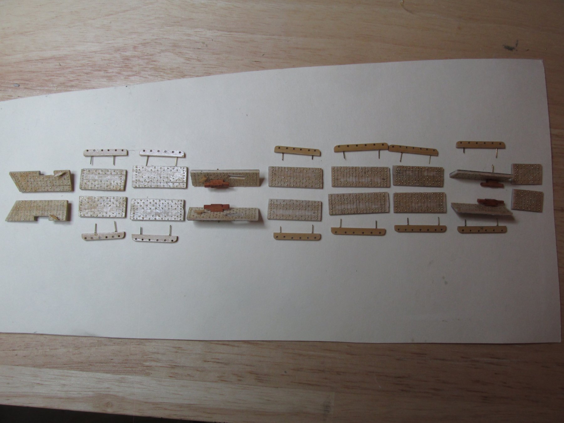
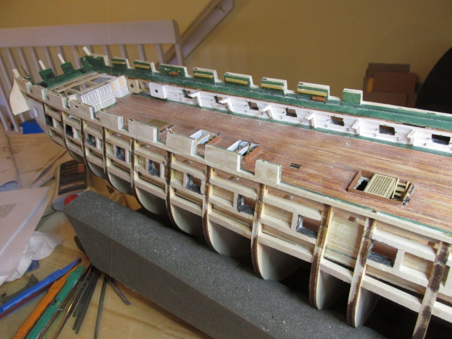
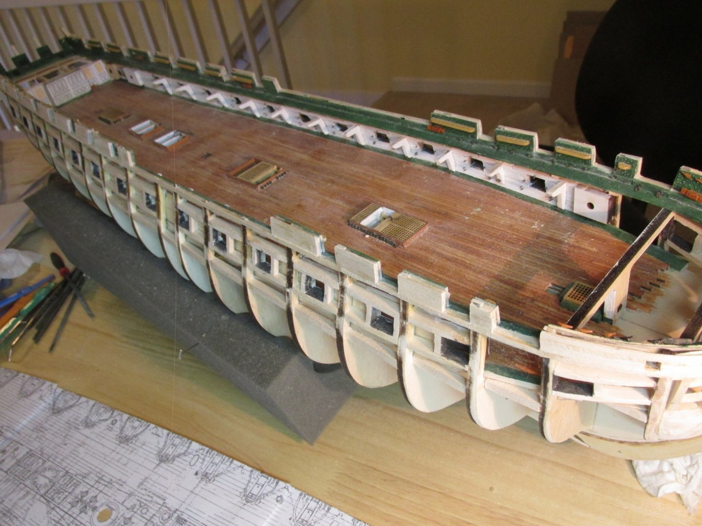
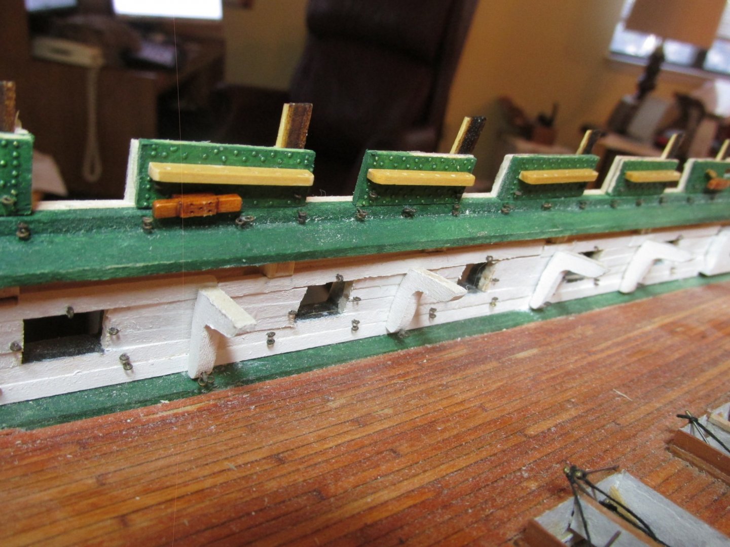
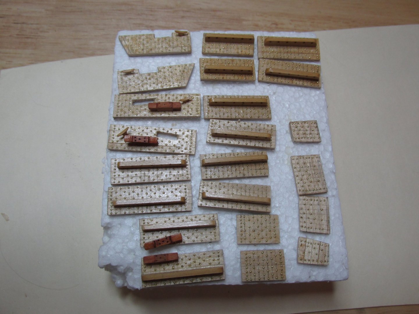
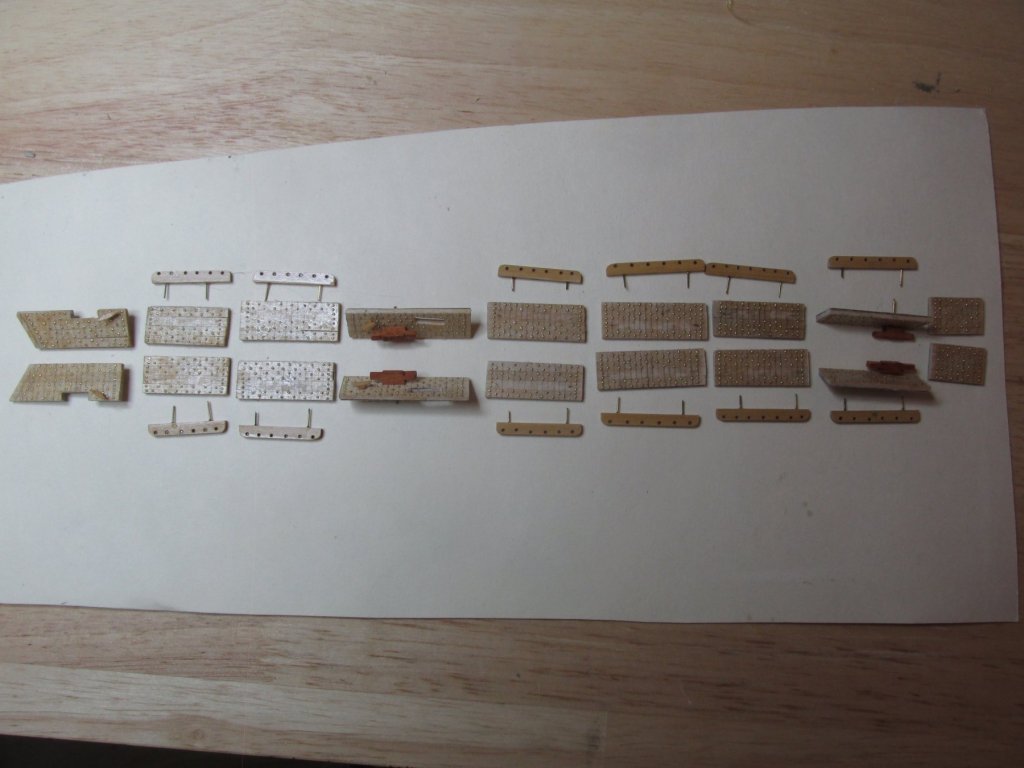
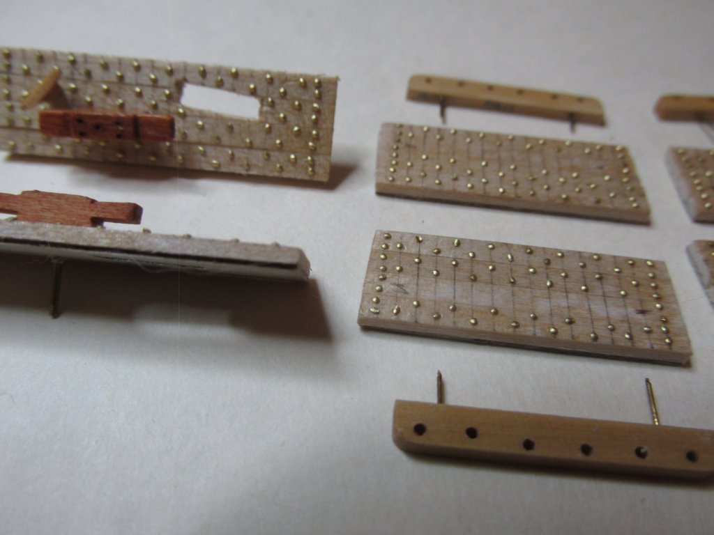
Almost a month has gone by. Where does the time fly???!!! I’ve completed adding the simulated bolt heads to the remaining starboard and port bulwarks. On average, each panel takes at most two hours of intense concentration due to the itsy-bitsy teeny weeny (that’s a technical term) size of the brass punched elements to punch, position, and attach them to the bulwarks. I still need to make the panels for the stern. I must have made about a thousand of them due including mis-shaped or lost pieces. I also wore out another punch, but because I got two replacement punches (no cost) for the one that broke earlier, I had a spare. In the images below, you will notice that I have dry fitted the large and small cleats. Their mounting pins have yet to be trimmed. You will also notice that four bulwark panels have a rectangular hole cut into them. These will become the bulwark sheaves. There is still a bit of work left such as fitting the pin rails, painting the bulwarks green and mounting them onto the model. Then of course there is the work on the stern bulwarks. All this will have to wait as I will be closing the shipyard for a couple of weeks for other personal activities.

-
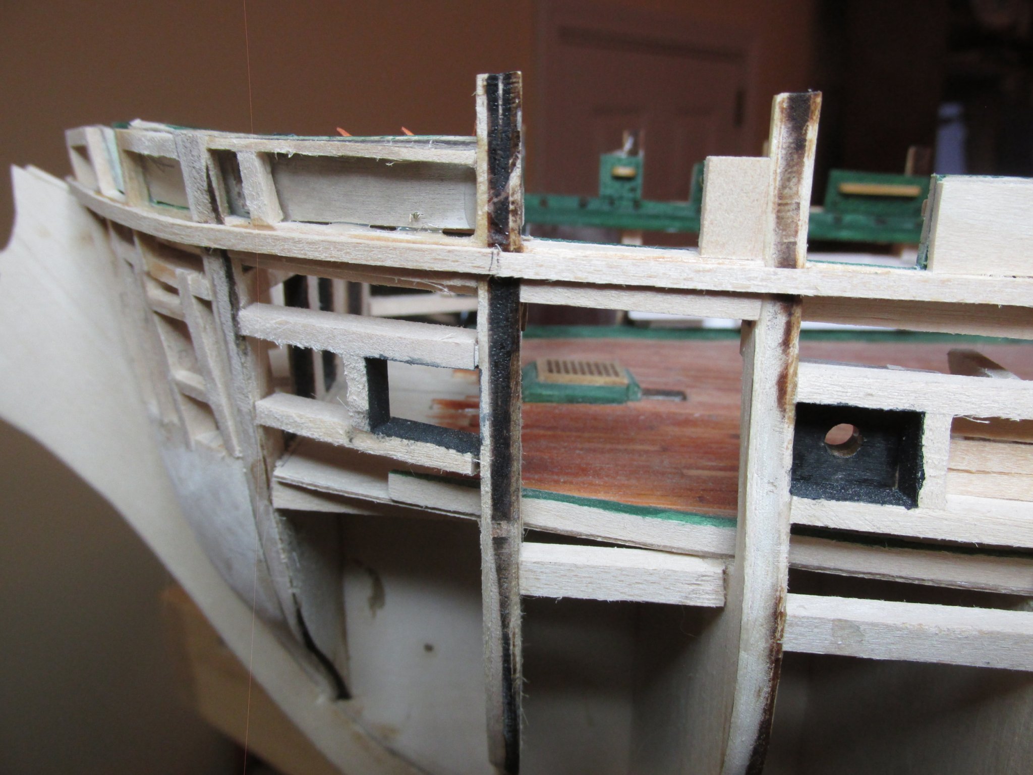
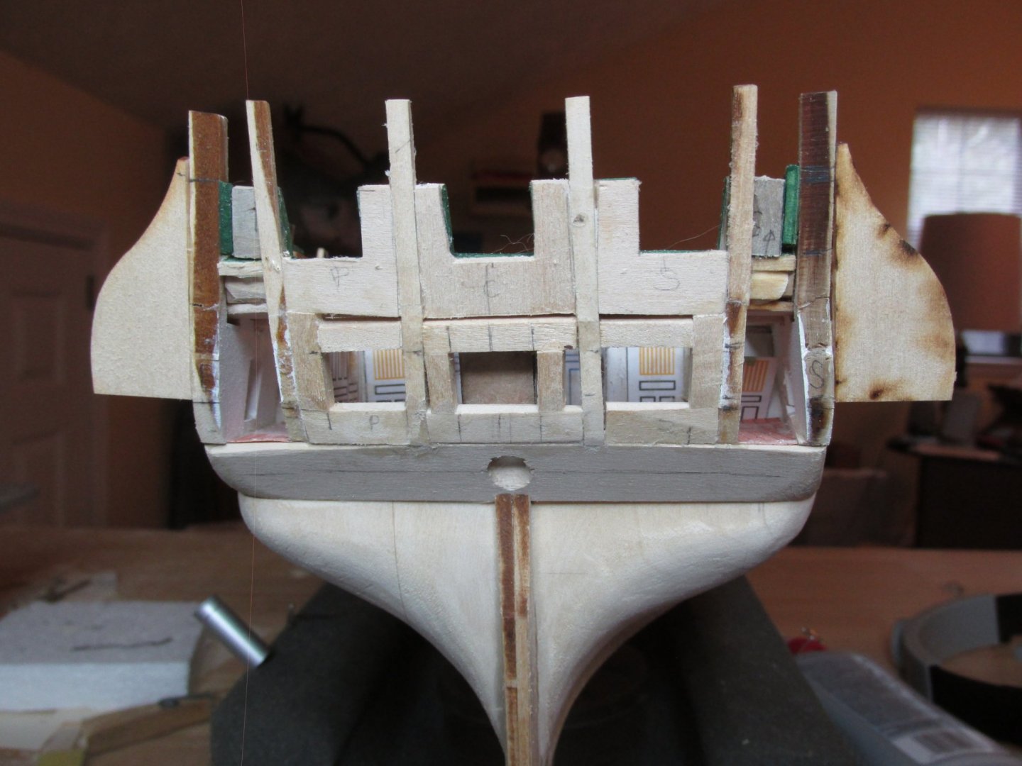
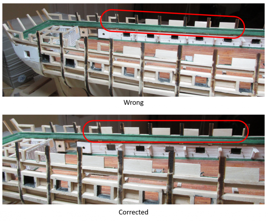
Luckily the fix wasn’t too hard at all. Due to the thin gluing surfaces, removing one frame and the solid wood pieces from each side was fairly quick and simple. A few delicate “wiggles” and the PVC glued parts came off. As rule, I’ve been using PVC glue on the framing so far to allow me the luxury of being able to fine tune the positioning before the glue set. That gave the joint a little flexibility which led to its ease of removal. The only part I had to remake was the first piece to the far left inside the red elongated circle of the “corrected” image below. The others came off the model so cleanly I was able to reuse them with a little fine tuning with a file. All I had to do was shift them aft. Note, I only circled the far side as it is easier to see. I now have to check all the plywood backed planking dimensions before I can proceed.
-
Well, I hit a near disastrous “oops.” If you go back into my log where I’m framing the spar deck gun ports, you will remember I switched from creating post and header frames to using solid pieces of wood. Unfortunately, On the last port before I made the switch, I got confused as to which side of the vertical post was to be the gun port and placed the horizontal header on the wrong side of the post. This moved the port to the wrong position. Then I created the remaining ports with the solid wood based on that last port. So, all the ports forward of the third gun port from the transom were wrong and those must be re-positioned. Since I was working both sides of the model at the same time, both sides were affected. I say a “near disaster” because I hadn’t finished the creating the bulwarks. I only made the plywood pieces with the glued-on planks. I could have punched out all the hundreds of bolt heads, applied them to the bulwark surface, painted them and glued them into position on the model. Or I could have been planking the hull wale like other builders at this stage. Hey, you have to look at the bright side. This error was discovered when I was trying to figure which bulwarks required the bulwark sheaves. The plans showed a wide bulwark and my model indicated it was a relatively narrow one. I’ll show the before and after images once I fix and make the “after.”
-
Lovely work Jeff. Out of curiosity, how did you anchor the guns to deck to achieve the taught rigging?
-
Finally, before I would fasten the bulwarks to the hull, I needed to add the cannon rigging eye bolts to both the bulwarks and the planking just above the waterway. I thought doing that now would be easier rather do doing it later. The blackened eyebolt openings are 3/32” dia. So, they may be difficult to see. Here are all the bulwarks so far (about 1/3) glued into place. The construct continues.