JSGerson
-
Posts
2,652 -
Joined
-
Last visited
Content Type
Profiles
Forums
Gallery
Events
Everything posted by JSGerson
-
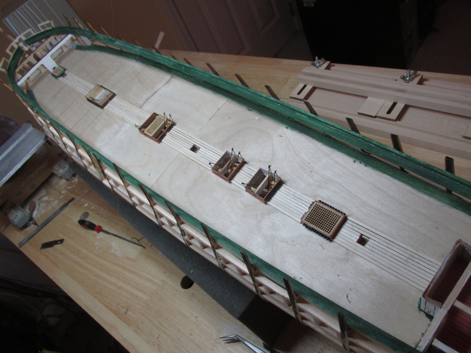
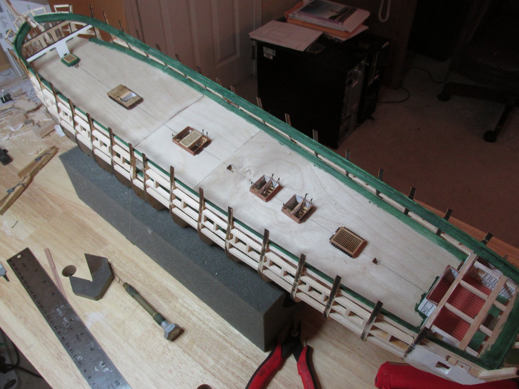
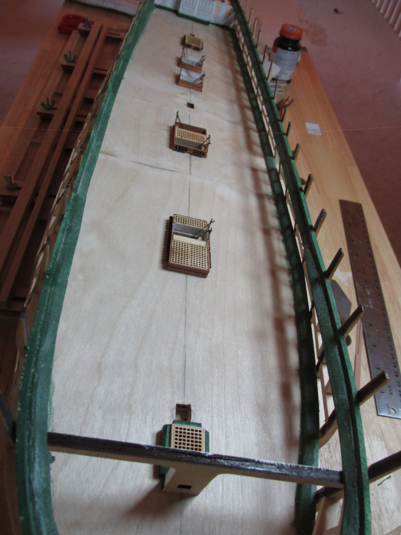
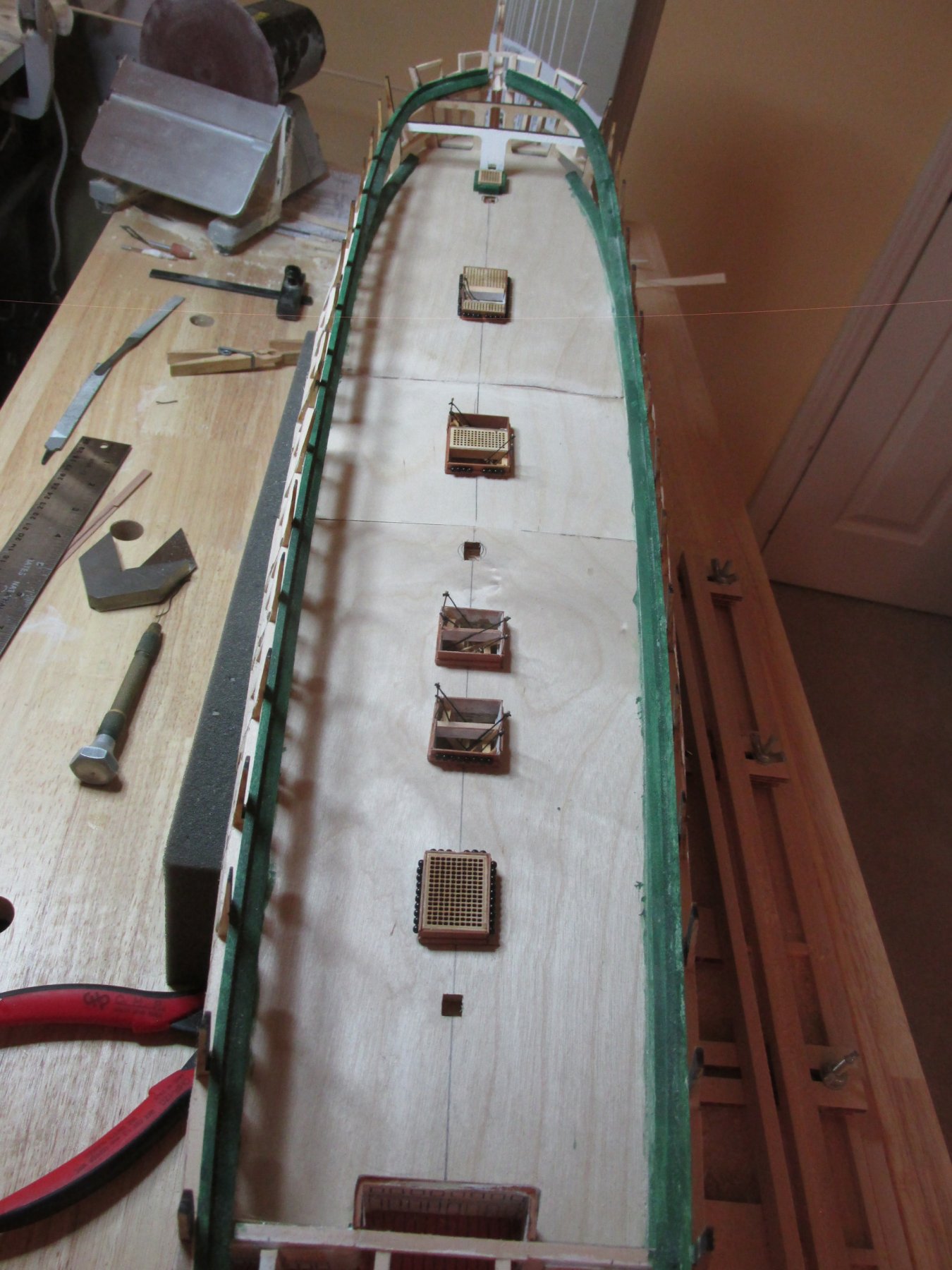
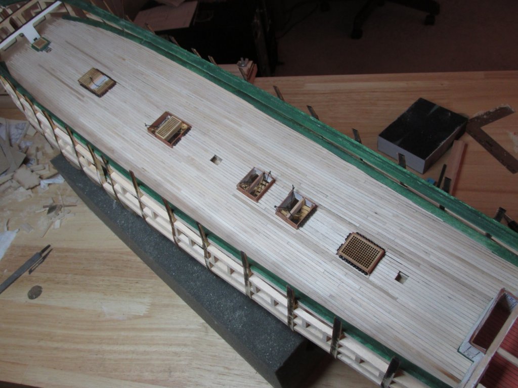
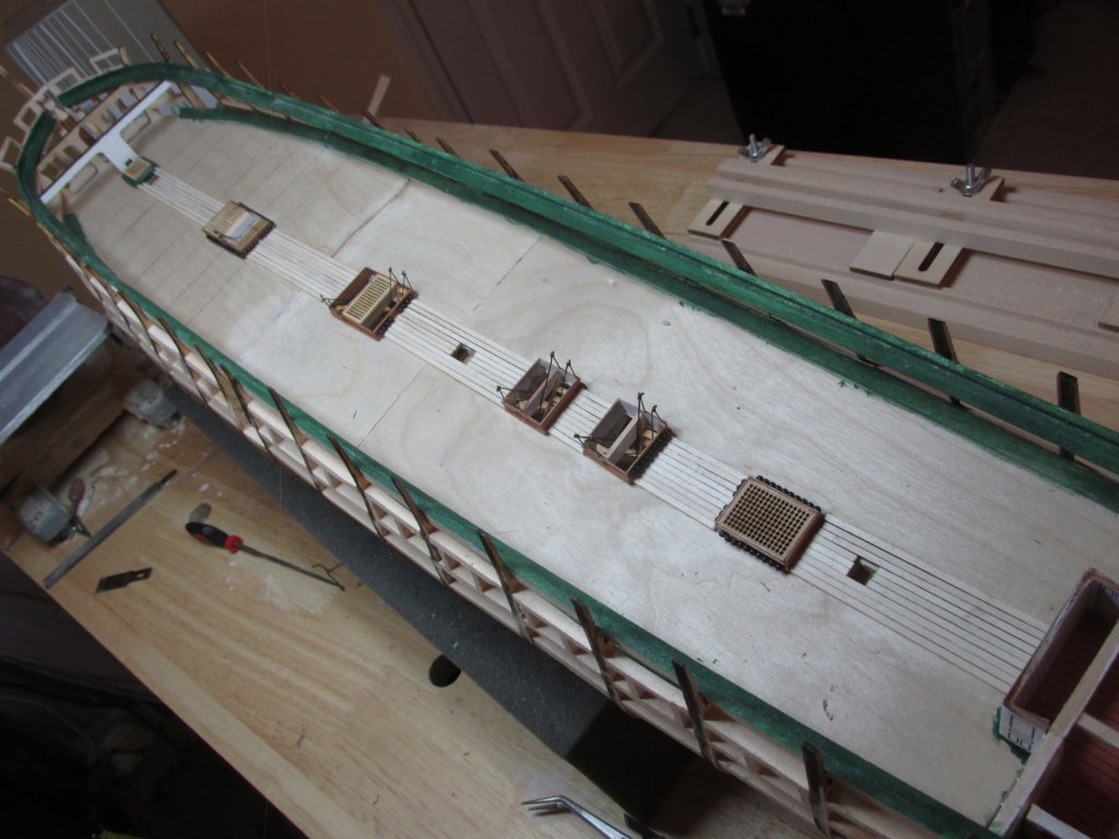
 Wow, a month has past by already. In between doctor’s appointments, hurricane Florence, and the what-nots, some progress has been made. I’ve completed planking the gun deck, but there is still work to be done on it before I can move on. The deck required about 45 sticks of 3/32” x 1/16” x 24” basswood. Surprisingly, I had very little waste, about 6” combined. As you will see from the images below, I managed to knock down almost every ladder stanchion so those will have to be repaired. The planks still need more sanding and then will need to be stained and sealed.
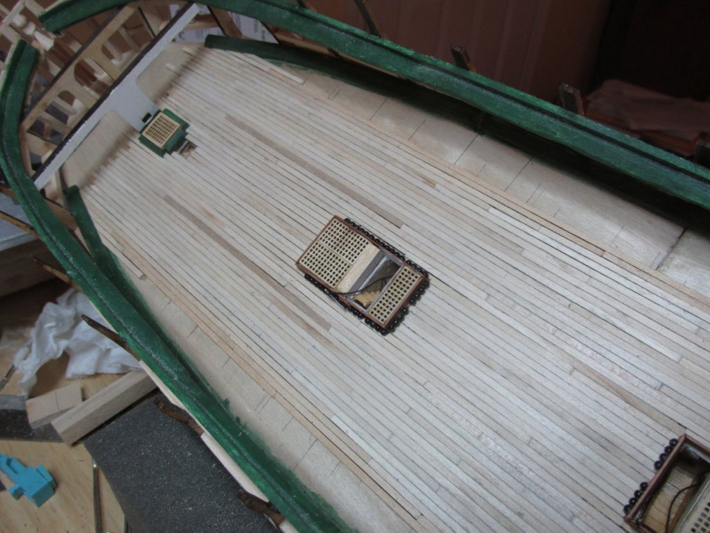

-
I don't know much about fishing line. You wouldn't happen to know, or point me in the direction of, the diameters of those lines you use? As you know, in our world of model building, scale is everything. Fishing line is about strength and the nomenclature of the line depends on what type of fishing is involved. Somewhere, somebody must have made a conversion chart of line strength to diameter. Even sewing thread is marked differently even among themselves depending on its application It's very confusing. I just want to know what the thickness is. Jon
- 742 replies
-
- 3
-

-
- constitution
- frigate
- (and 1 more)
-
Very neat and pretty. Out of curiosity, what miniature rope are you using. Typically I use Chuck's rope from Syren Ship Model Company, the kit's rope, and sewing thread but usually have a problem with very fine line for example flag halyards or ratlines. You have an advantage with your slightly larger scale build which makes even normal sewing thread seem relatively fine. The lines shown on your bowsprit are beautifully delicate. What did you use? Jon
- 742 replies
-
- 3
-
-
- constitution
- frigate
- (and 1 more)
-
I feel very relieved you were spared. Living in the western part of South Carolina, I too was lucky; I barely even recognized that there was a storm going on to the east of me. I hope the relief effort for the rest of your community moves swiftly and all will be back to normal soon. Looking forward to your progress pictures. Jon
- 742 replies
-
- 7
-
-
- constitution
- frigate
- (and 1 more)
-
I'm just a couple a three hour hours away from you, and you would think I was on the other side of the country; blue sky, puffy white clouds, with just a few gusts of wind. I'll probably have more weather this weekend. Take care and keep safe. Jon
- 742 replies
-
- 6
-
-
- constitution
- frigate
- (and 1 more)
-
Thanks Ken for the "look in." Your build will be one of the main build logs I'll be using as a guide as my build syncs up with yours.
-
Well, that sucks. I was looking forward to more posts. I assume it was the transom that took its toll on you...plus the lights...plus the 1812 modifications...plus... plus... plus... Sorry to see it end this way. I look forward to your next endeavor. Jon
-
The way I belayed the preventer lines into deck eye bolts on my Rattlesnake was to pre-drill the eye bolt holes early on. When the time came, the eye bolts were then rigged to the preventer lines. The whole rigged eye bolt was then inserted into the pre-drilled deck hole. This eliminated trying to thread through the eye bolt and seizing the lines while the eye bolt was attached to the deck. I know it's too late now, but maybe this tip will help someone else or you on a later build. Nice work on the ratlines by the way. Jon
- 742 replies
-
- 4
-
-
- constitution
- frigate
- (and 1 more)
-
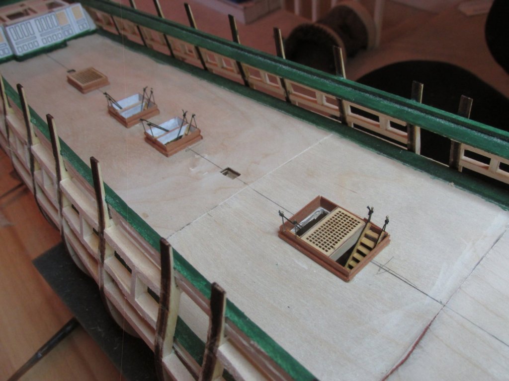
Gun Deck Planking Now that the gun deck hatches and ladders have been installed, it was time to install the gun deck planking. After a little research, I’ve determined that the deck plank length vary from about 16’ – 30’. The distance between the various hatchways and scuttles is well within those limits. Therefore, there would be no planking joints when planking in those areas. Robert Hunt’s practicum also reached that conclusion although he was only dealing with the spar deck. Using artist’s charcoal, I colored just one side of each plank which worked well. I had originally thought to use CA glue to fasten down the planks, but I found the CA glue soak too quickly into the plywood subdeck. Making the glue bead thicker just made it messier with no time to adjust plank positions. I resorted to wood glue (Wellbond) and had no problems. I added lines perpendicular to the beam on the subdeck to represent the underlying gun deck support beams. This is where plank joints will appear and line up as necessary.

-
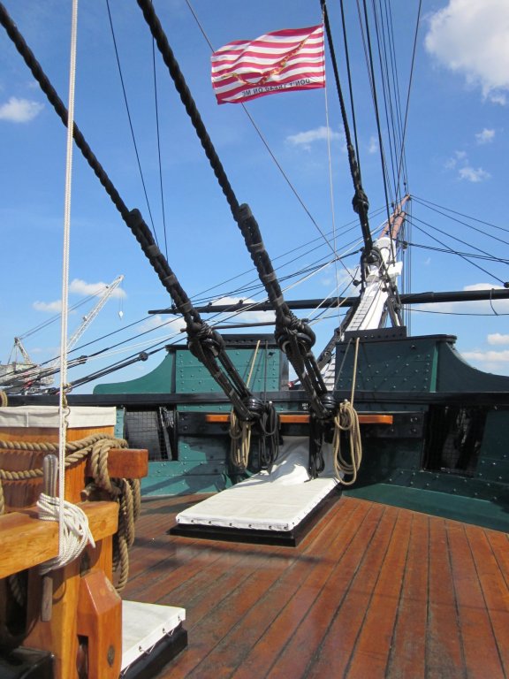
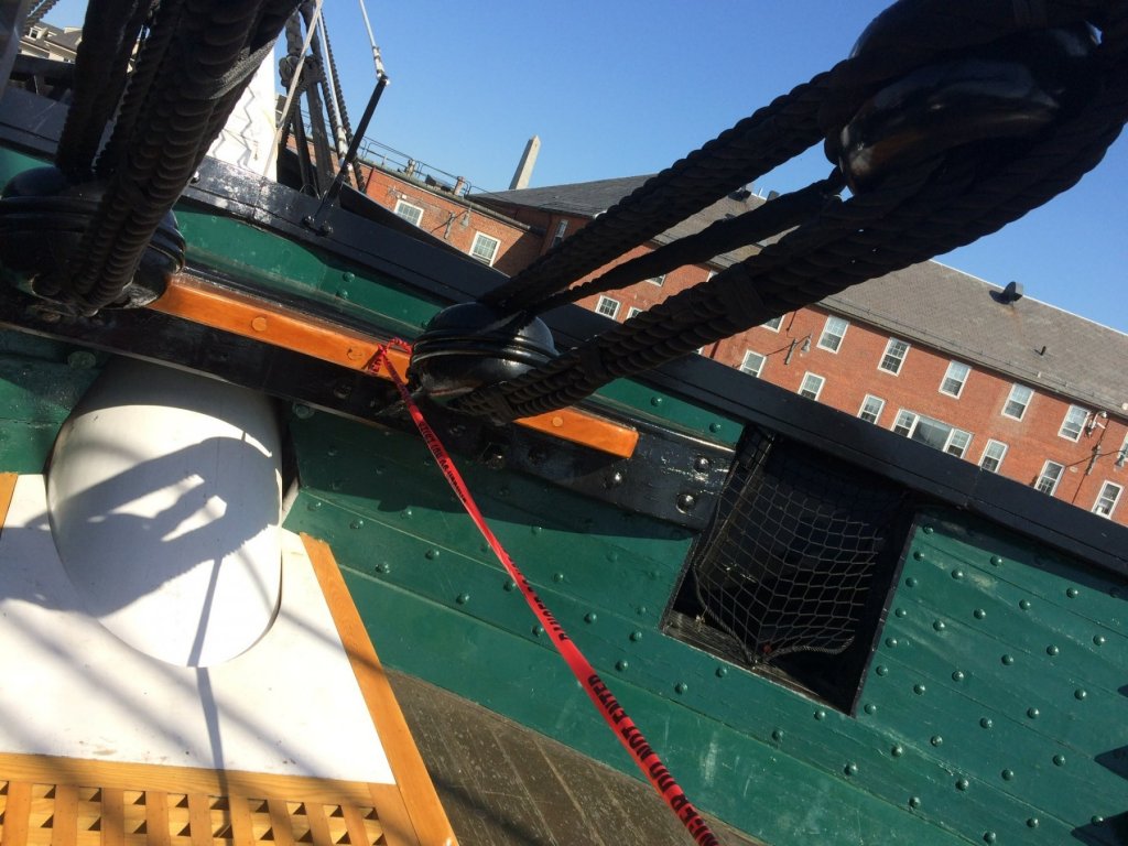
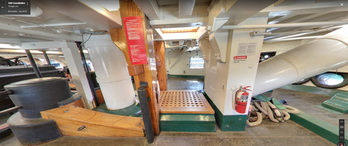
I have a question about the recent overhaul the USS Constitution just completed. I was poking around various build logs and sites looking for detail images that I could use in constructing my model of the Conny. On JerseyCity Frankie's log U.S.S. Constitution Turn Around Cruise 6/8/18, he had an image of the bow looking forward where the bowsprit starts. The structure atop of the railing which looks like a wave breaker (my term) has been removed. JerseyCity Franklie only provided the one image which leaves a lot detail to be desired.
I've included a before image and JerseyCity Franklie's "after" image.
I am curious as to why the change was made and if you could provide any more images. I would like to incorporate this latest modification into my model.
-

The origins of the topgallant rail and bulwarks on the Constituion are some time around the 1927 refit, I believe. At that time the Navy decided that the bulwarks all around the ship should be raised and to have bulwarks at the waist installed to the same height. You do not see them, obviously, in this photo but they were done completely around the ship.
I forget which year it was, but during the refit before this last one the decision was made to bring the ship more in line with her 1812 configuration. To that end, the bulwarks in the waist and the topgallant rails were again removed, as you see in your second photo. Also at this time the proper camber was built into the deck, the thick planks (or king planks) were put into the deck, and the diagonal riders were installed in the orlop.
Regards,
Henry
-
I knew the bulwarks at the waist were removed to conform more like 1812 but did not know about the top gallant rail. All the images I've seen except the second one, show the rail. Any chance getting more images without the rail?
I assume that the lines that use to go through the holes at the top of the rail terminated at the belay pins below it; so that now they go directly to the belay pins. Is that correct?
Thanks for your help.
Jon
-
-
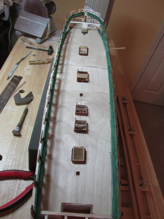
So, as it stands, this is what 8 months of work on the hull has accomplished so far. Just cruising along 8-)


-
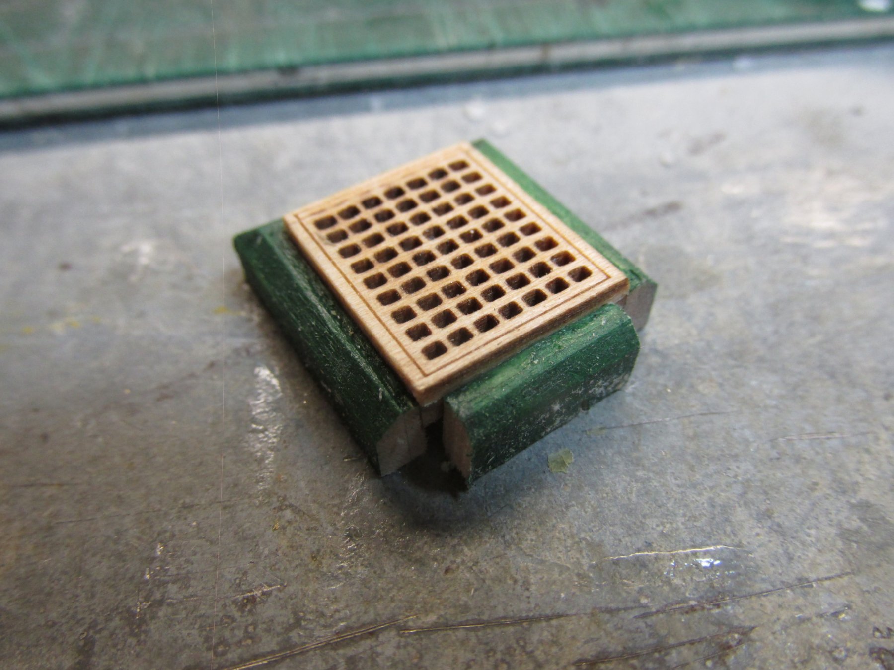
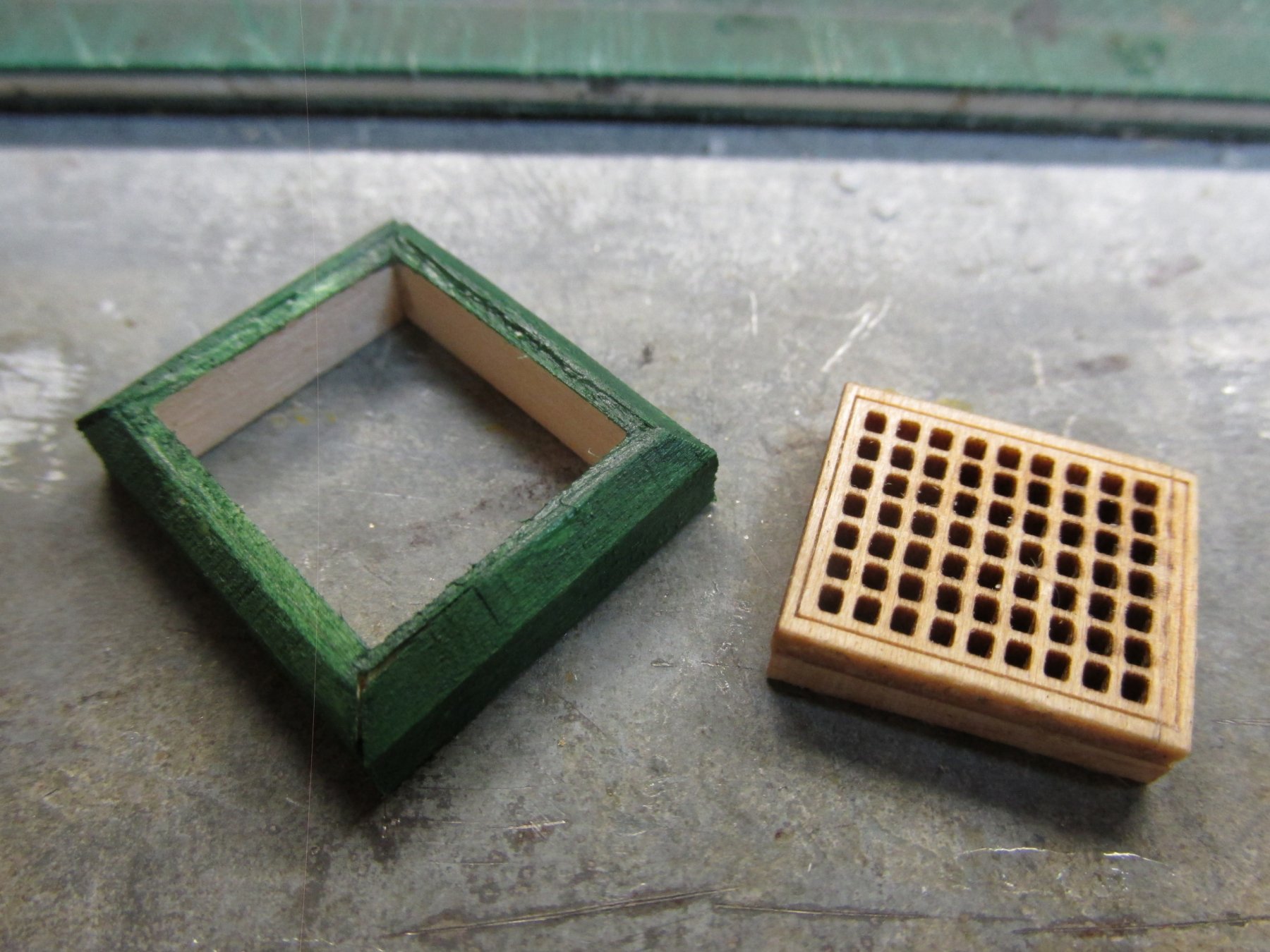
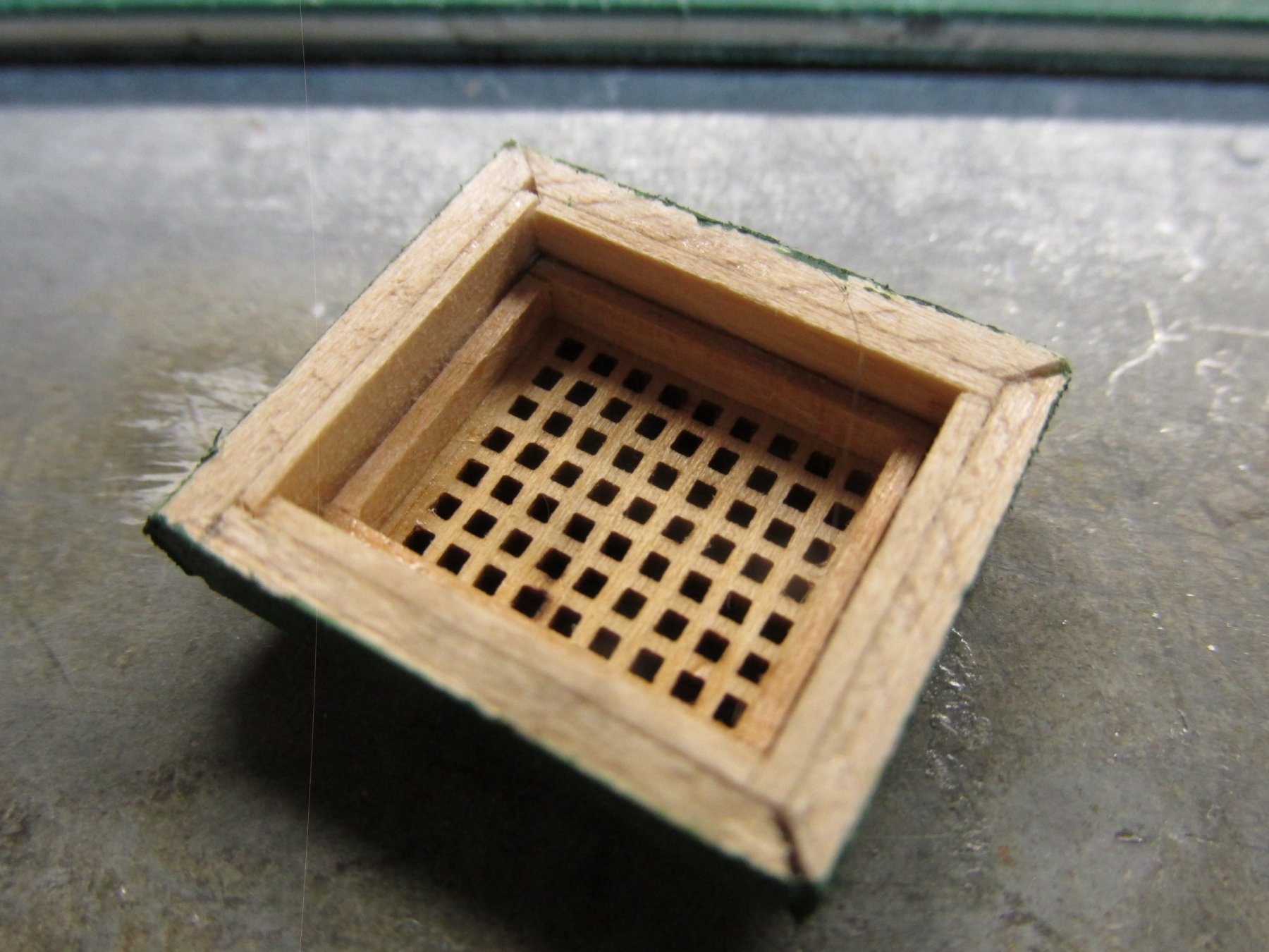
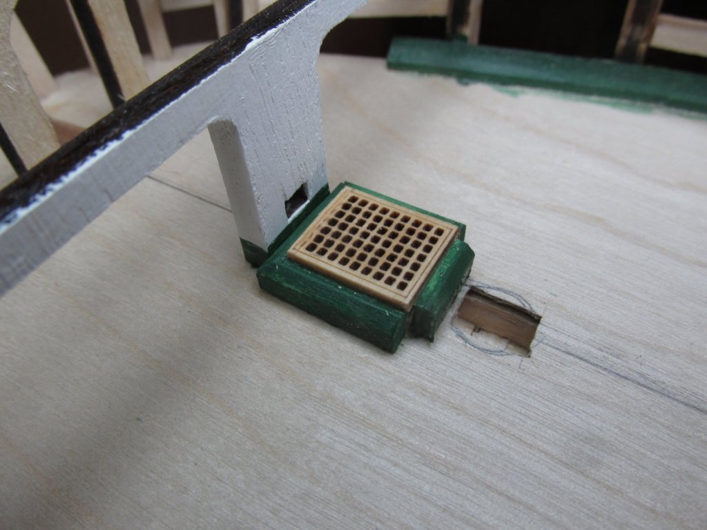
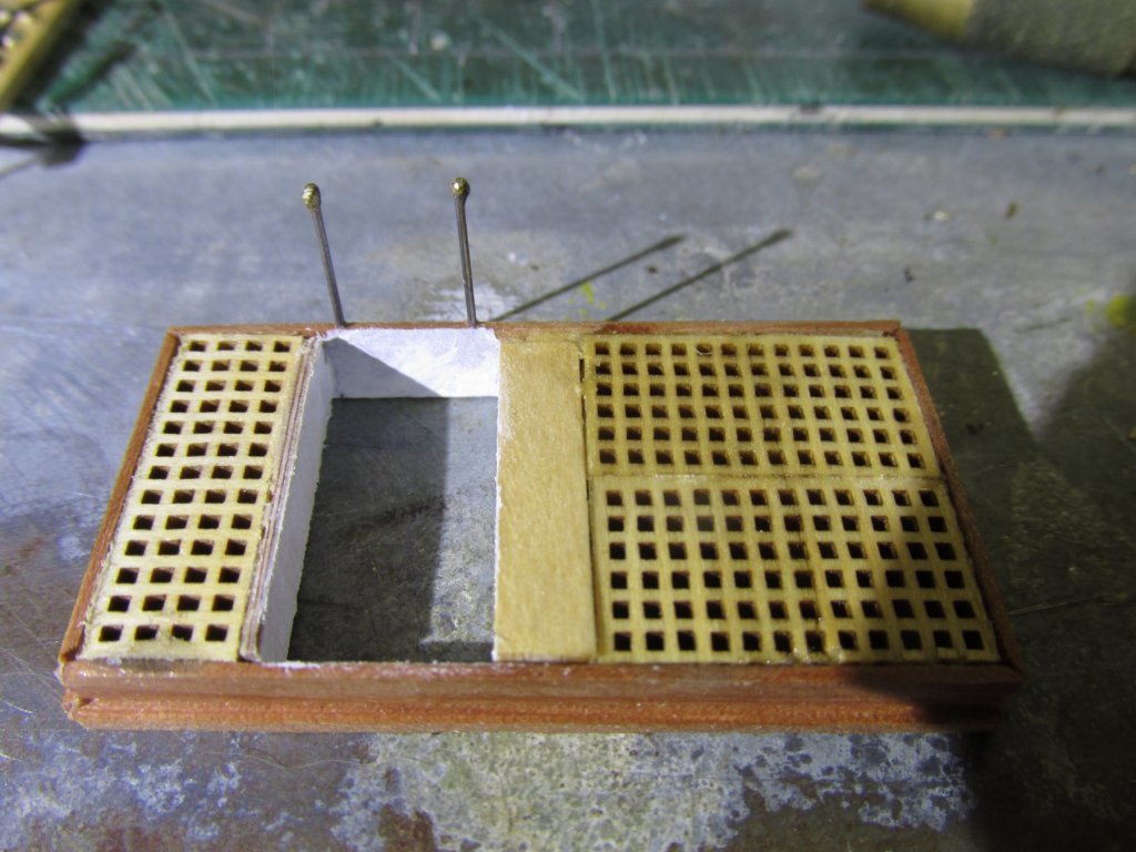
At this point I thought I was done, but then realized I needed to do one more thing. If you look at the picture of the actual scuttle (above), you will notice there is a post on either side of the scuttle where vertical posts are. They notched into the scuttle frame Using my Byrne’s saw, I very delicately cut out the notches and painted them. The bow sprint support was painted, and the scuttle was set into place. The kit’s bow sprit support brace is the furthest forward I plan to add details on the gun deck.

-
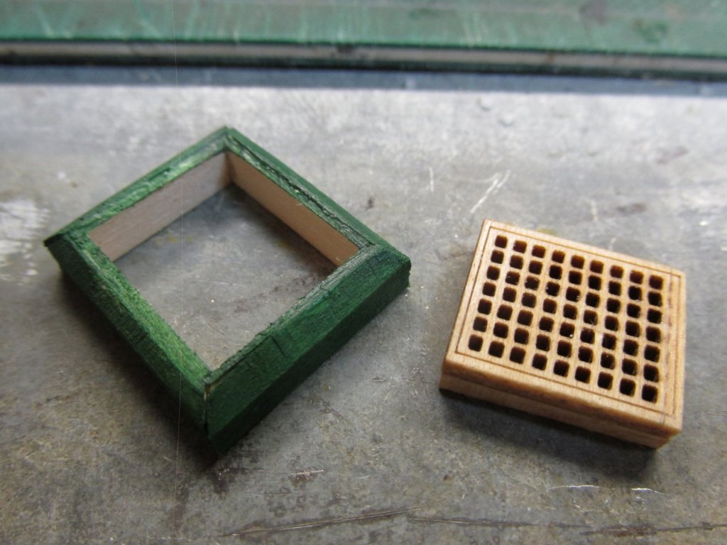
The frame was then painted green. I’ve flipped the structure over so that you can see the underside construction.

-
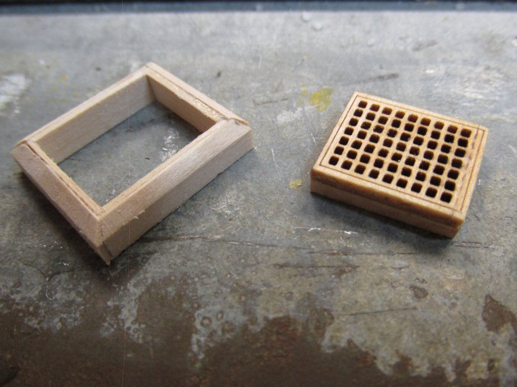
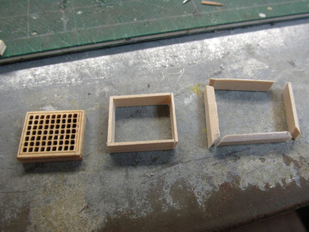
The beveled frame pieces were glued individually to the inner frame. I know this could have been done with four pieces of stock instead of eight, but my problem was the bevel. I don’t have a proper tool to cut a bevel along the length of a piece of wood accurately. I was able the cut the bevel on the outer frame with my disk sander.
-
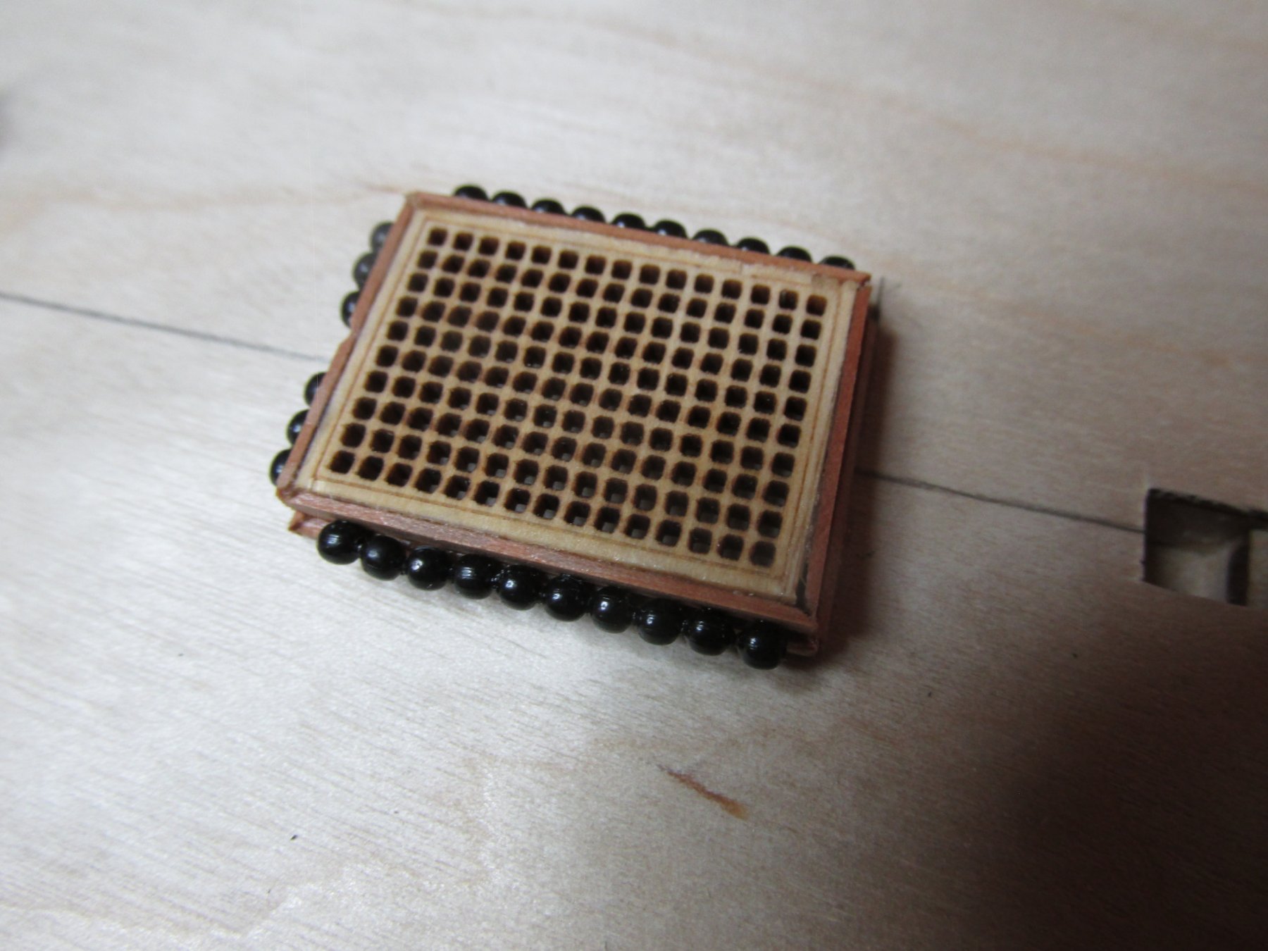
As with the previous gun deck hatch gratings, I used the grating stock I bought earlier. After creating the size I wanted, I extended the side walls by 1/32” to eventually raise it above the grating frame. Then I created a frame to go around the grating. Finally, I created another frame that was beveled on the top edge
-
I thought I was done with the gun deck gratings, but upon checking the Navy plans, it seems I missed one. This was labeled “scuttle” on the plans and it is just aft of the bowsprit support. This one’s a little different from the hatchway gratings as its grating is raised above the scuttle side walls and is painted.
-
As I noted above, I did consider it. The gun deck is going to be only visible through the open areas in the spar deck planking and deck floor support beams. Therefore, the lighting will dim on the gun deck as well as relatively distant from the viewer. So considering the amount of effort required to make those racks, for something that won't be seen unless you have a keen eye and a probe light, I elected not to make them. I will however attempt to make them for the gun deck.
-
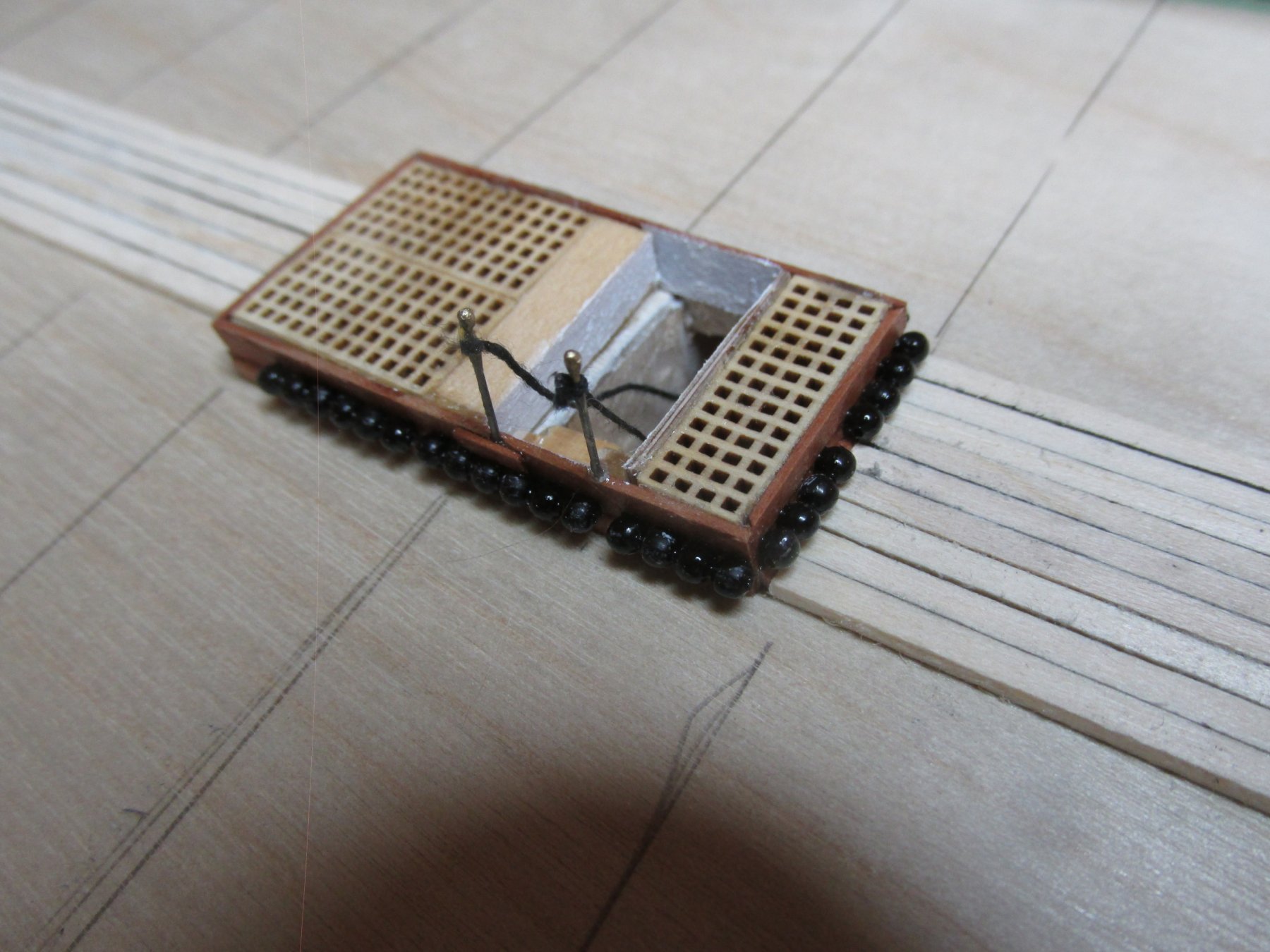
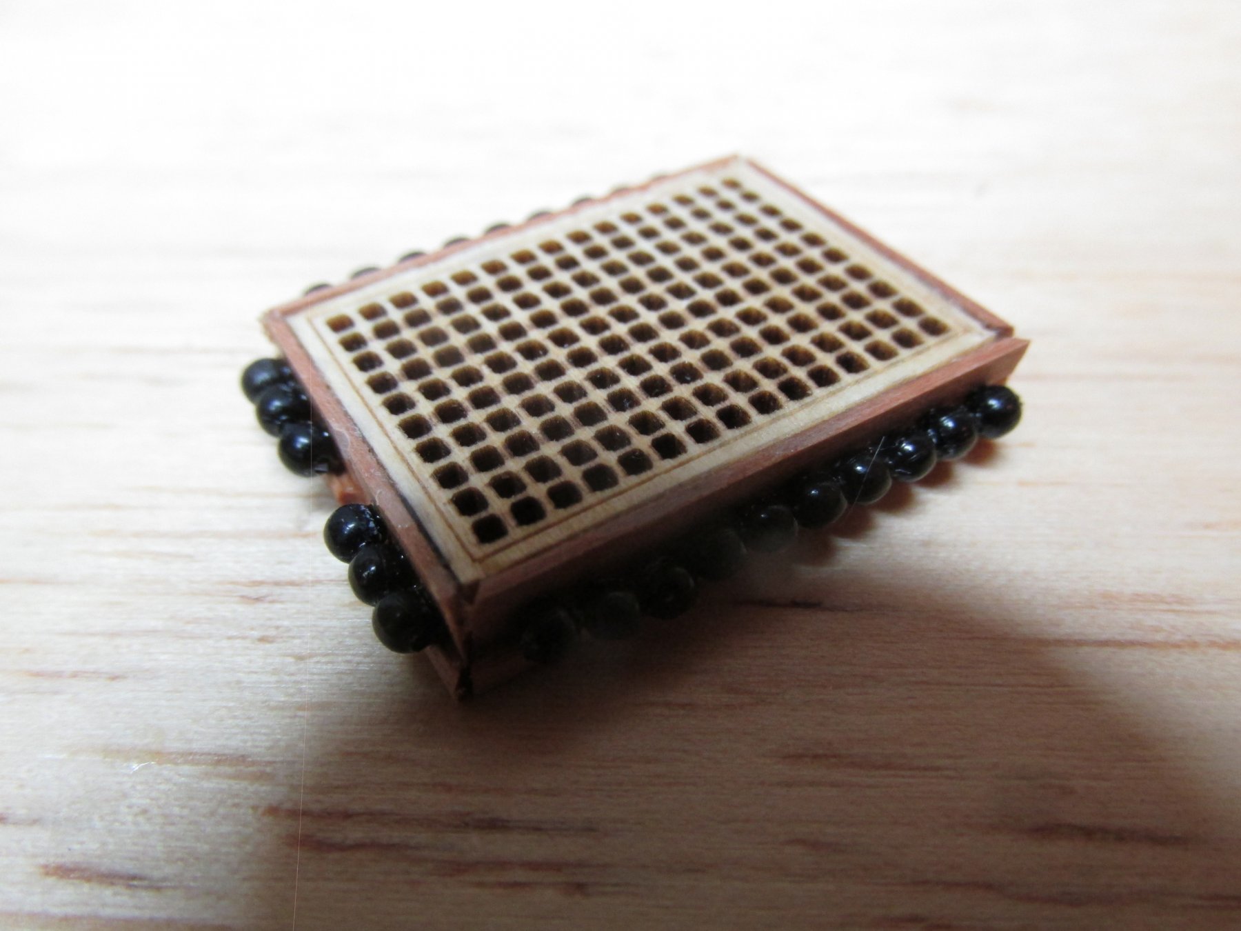
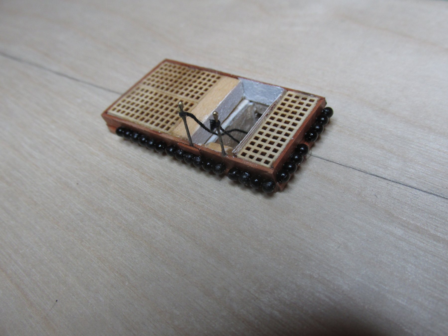
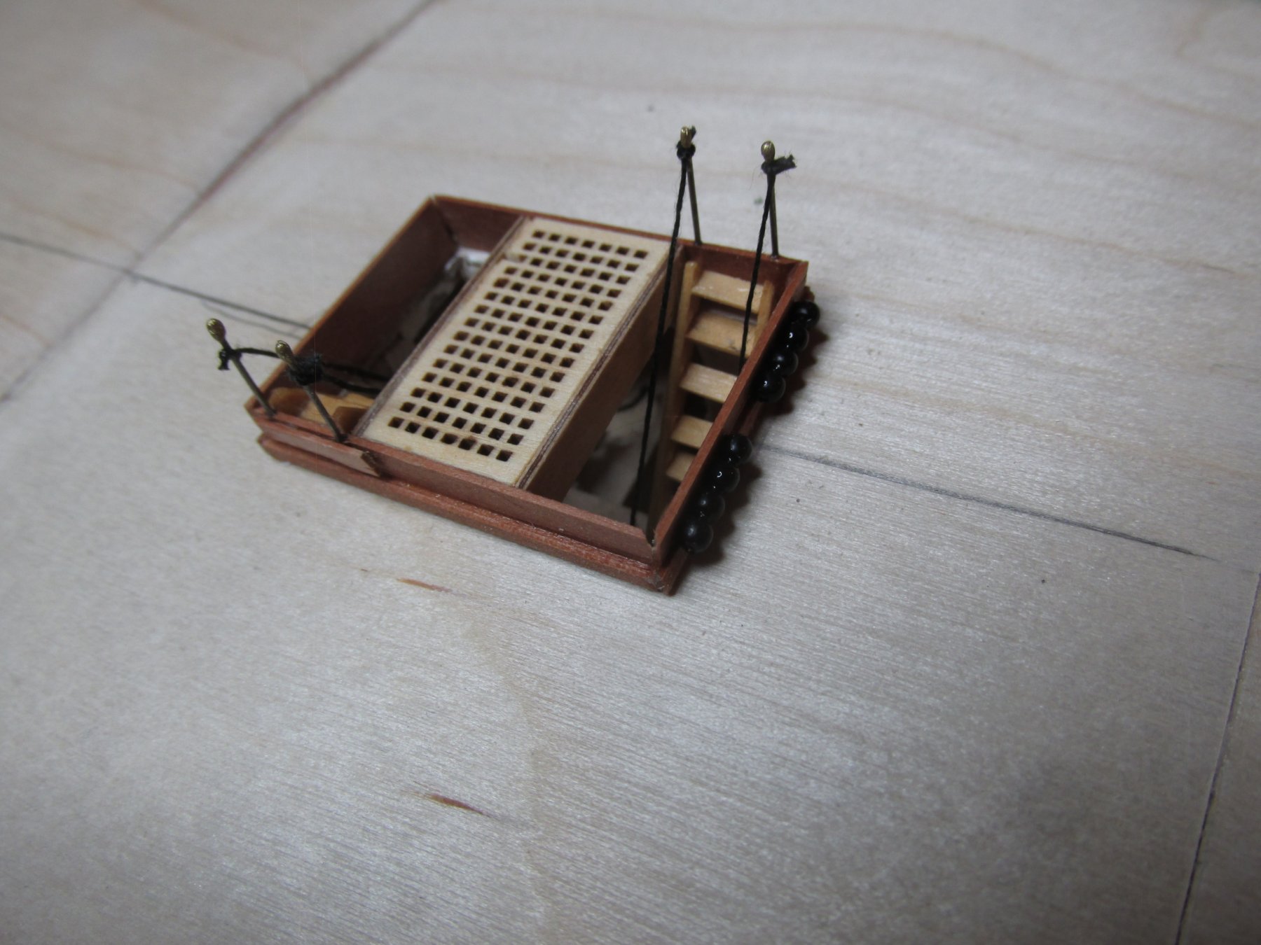
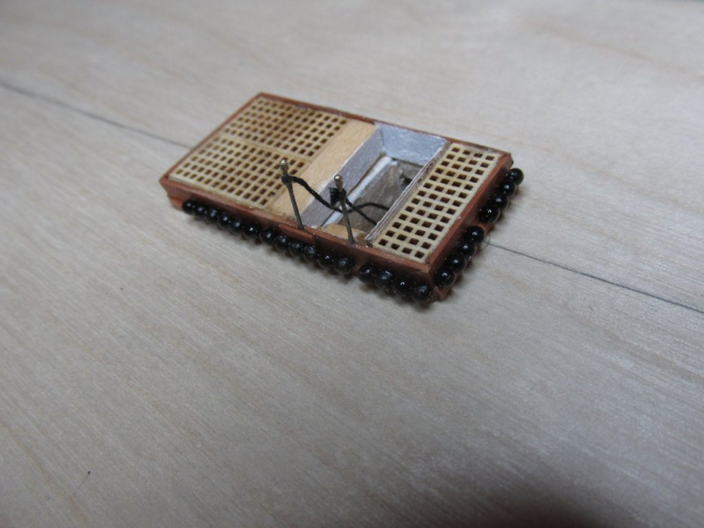
Since the chain was already colored black, no color preparation was required. All that was needed was to cut the appropriate length of chain. When laid down on the side of the skylight, the chain was push together so that the links were not visible. In fact, the links made handling quite easy. At this point I had a decision to make: add the ball racks or not. My modeler’s gut reaction was to at least attempt to make them. The practical side said no, no one will see them due to the awkward viewing angle and lighting, not to mention how difficult and delicate they would be to make; at least not on the gun deck, maybe on the spar deck. That was all fine and good for the skylight, but if the cannon balls are to be installed there, I should also install them on the other appropriate hatches. They, however, would be a bit more difficult since they were already installed on the gun deck. By tipping the hull frame on its sides I was able to place and glue the balls into position with CA glue. For those balls which had to be installed on the for and aft sides of the hatches, the hull frame was supported on its transom and stem


-
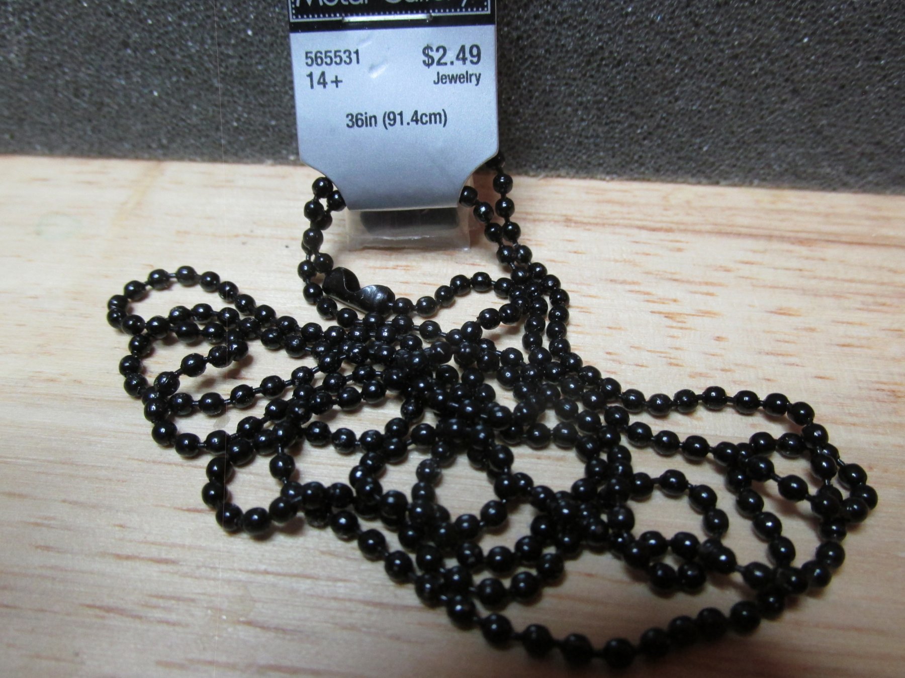
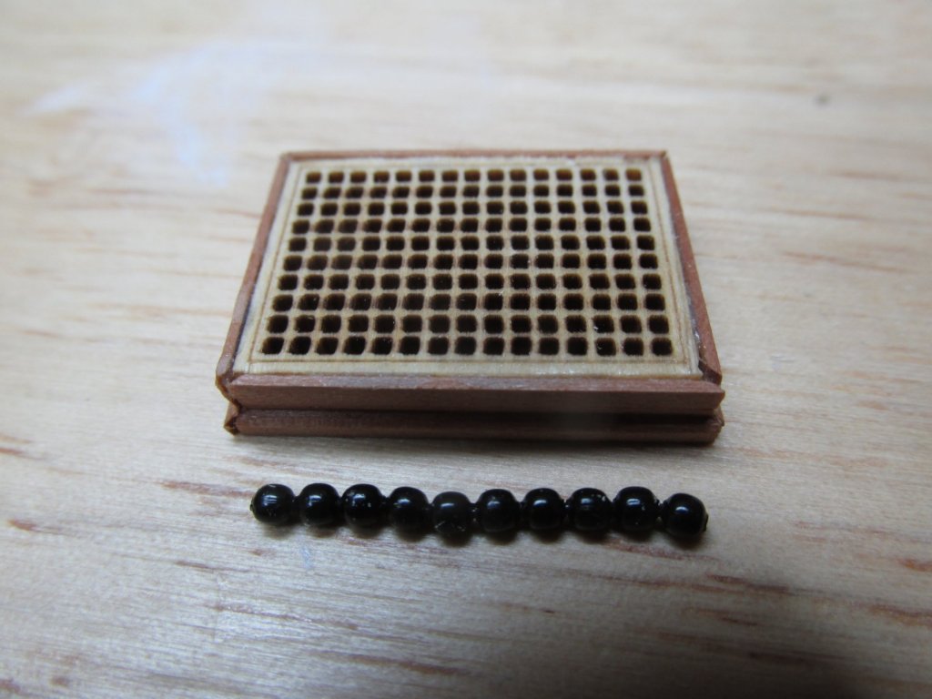
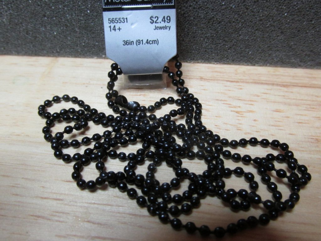
Cannonball Racks After I added the printed detail on the Captain’s cabin complex, I realized I hadn’t installed the Wardroom skylight grating. I then realized that now would be the most opportune time to add the cannonball racks to the skylight. Because the kit did not provide anything to construct the gun deck, I needed something to represent the cannonballs. Taking a cue from xKen’s (a.k.a. Ken Forman) build, I purchased some black 2 mm ball ball-chain from the jewelry section of Hobby Lobby. The ball size is close enough for this scale.
-
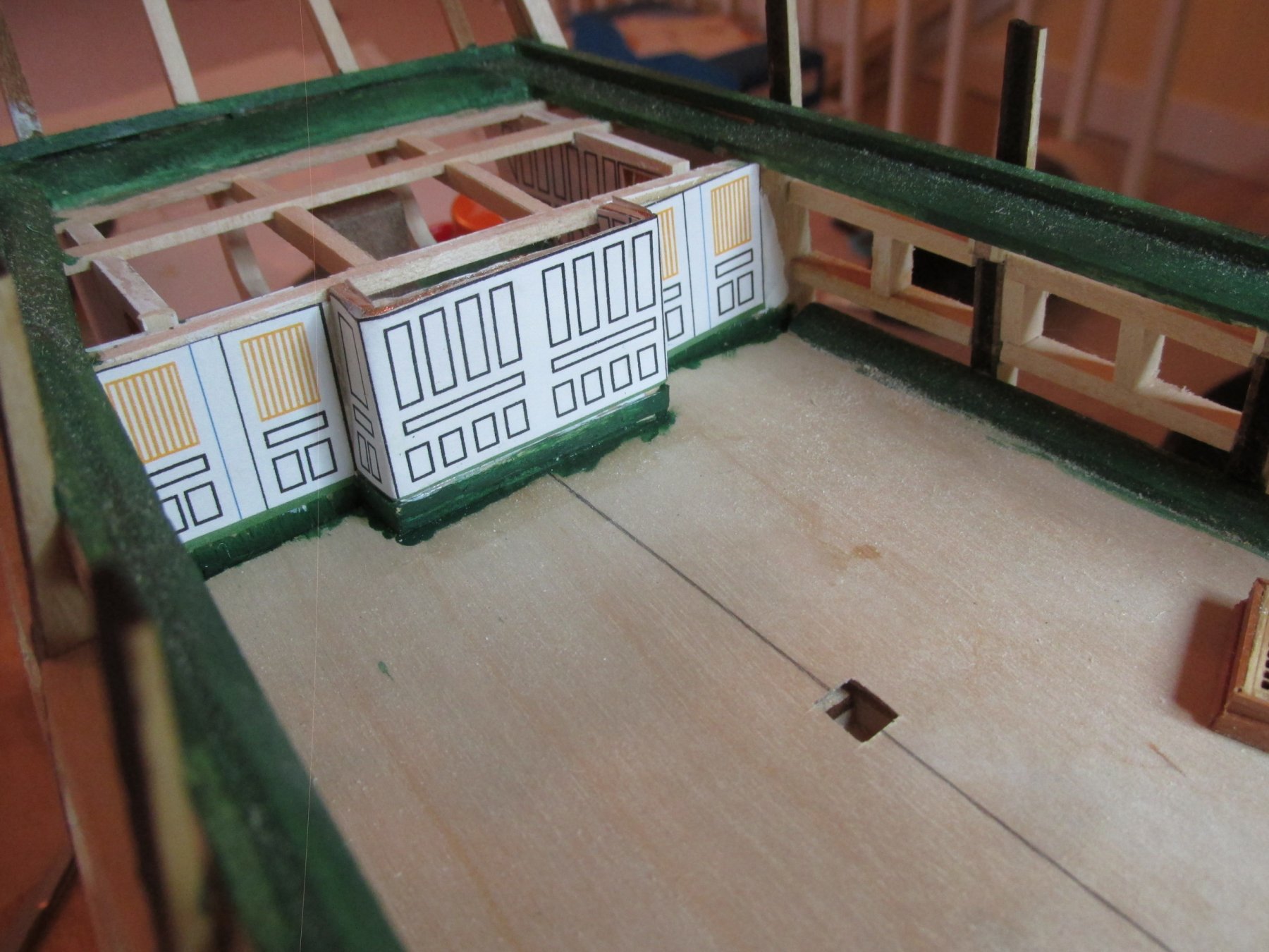
It’s been over a month since my last post. My life has been turned a little topsy-turvy due to my back issue. I’ve been diagnosed with a curvature of the lumbar region of my spine with degenerative disc disease and at least one herniated disc so now I walk with a slight hunch and a bit of pain (sometimes more, sometimes less). The CAT scans and X-rays were not pretty. The good news is that the physical therapy has helped reduce the pain, so I can stand and walk for longer periods of time. Thankfully I get almost total relief when I sit. I was told that if surgery is in my future, it will be complicated and very risky. Oh joy. That being said, I did manage to move forward with build by completing all the stairs going to the berth deck. For something most viewers won’t even see unless they look really close, Still, I had to put in a fair amount of detail. I even prepared the forward-facing wall of the Captain’s cabin complex. It is like the transom cabin with printed detail due to its inaccessibility to the viewer.

-
Very impressive. I too am planning to add bulwark "rivets" But as small as these plastic rivets are, to my eyes (and I use that term lightly as I am blind as a bat without my trifocals), they still seem too large for the scale, especially the height above the surface. I have yet to reach the point in my build where I need to install them so I haven't done any experimentation with various methods I've seen. It may very well be I'll end up doing exactly as you did. If so, I hope to attain the beautiful craftsmanship you achieved. Jon
-
Doc, I had a laminectomy (no fusion) in 1979 and I was pain free until this year. I have no idea yet if the culprit is at the same location or elsewhere. I should know in a few weeks. I am truly sorry about your condition. So far no epidural injections or MRI's (can't have those, I have a pacemaker) and I guess I have not had any EMG's because I don't know what they are. I hope whatever procedure you do end up with works because the alternative is not pretty.
-
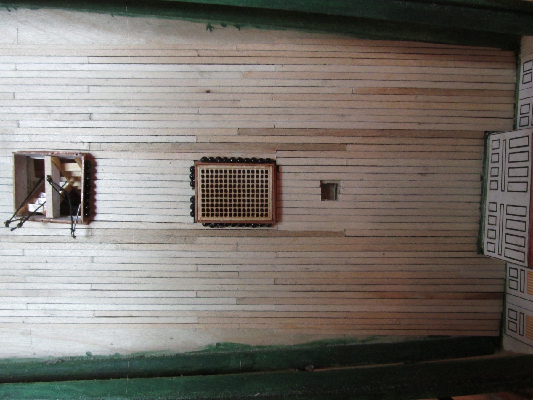
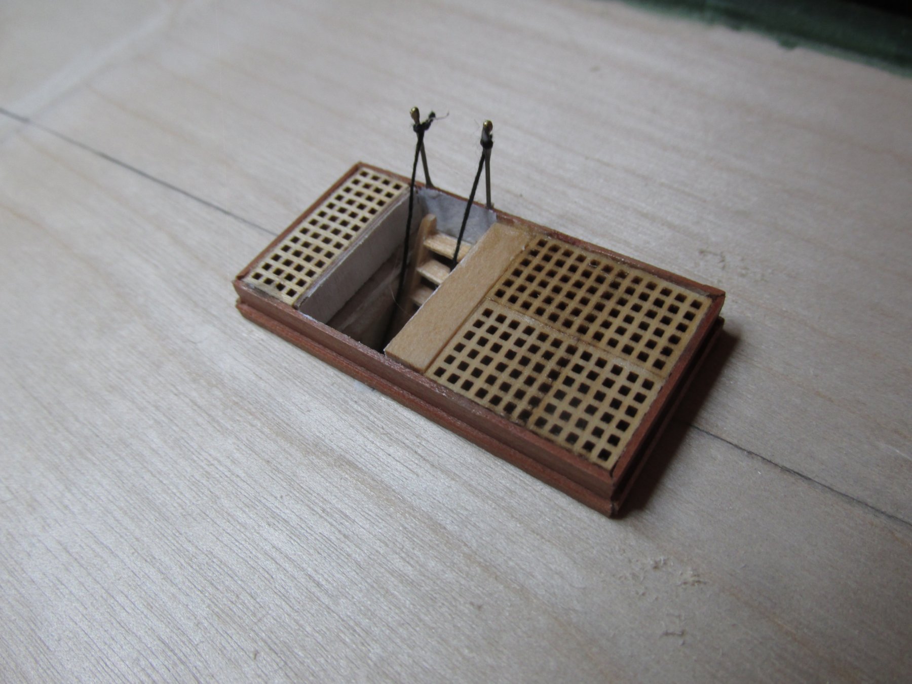
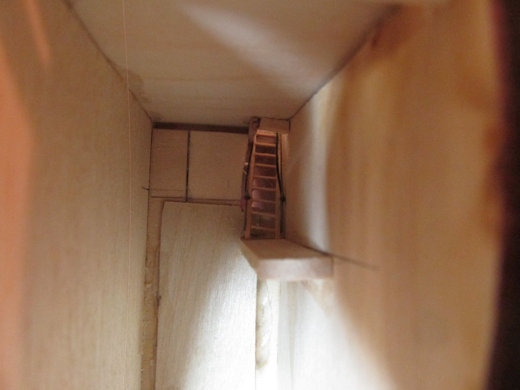
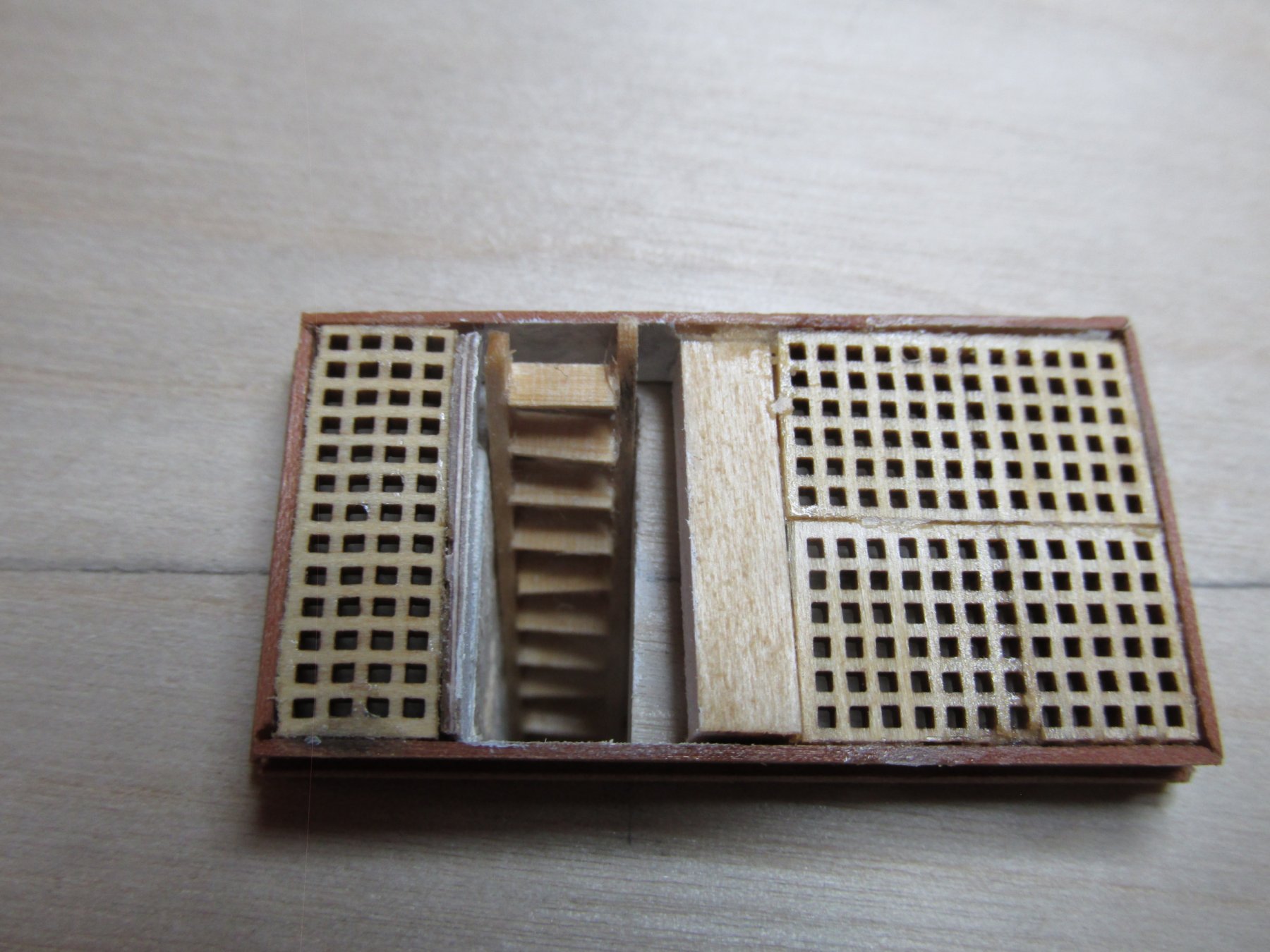
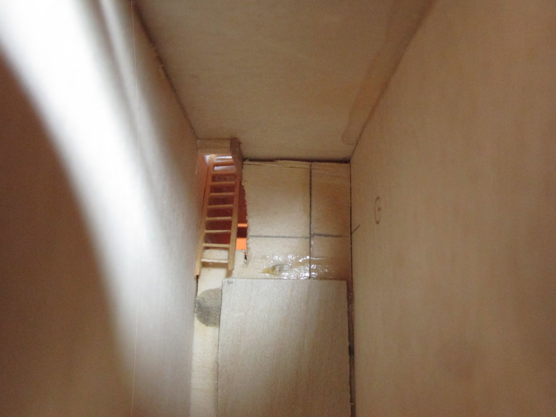
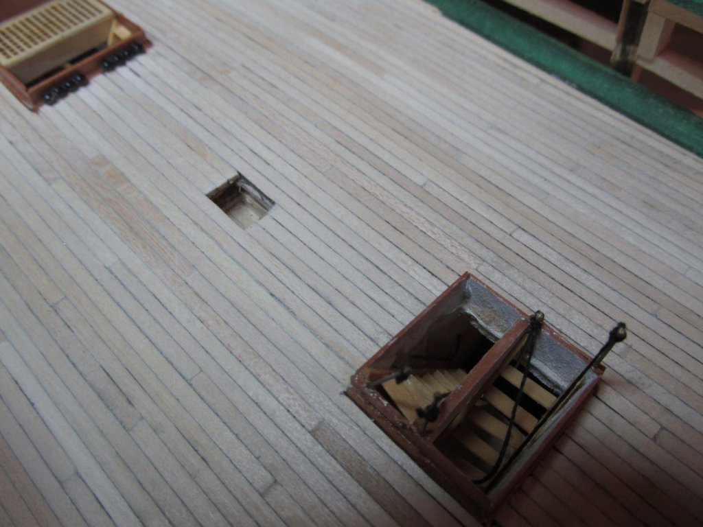
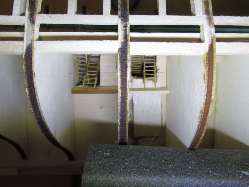
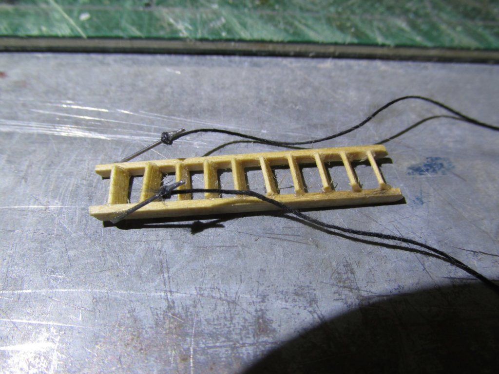
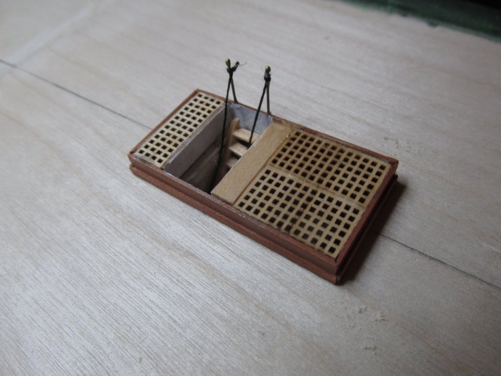
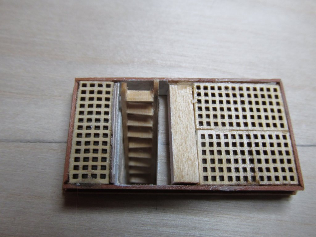
I’ve glued a piece of wood to act as a support for the first ladder and I’ve completed all the remaining ladders that go from the gun deck to the berth deck. To install the ladders, the hatches must be glued in, but before I can do that, I had to add the two hatch stanchions that hold the hand ropes. Two more stanchions were added to the base of the ladder and tied with a length of 0.3mm “rope.” The stanchions were made from 0.02” music wire. For the hatch stanchions, I added a tiny blob of PVC glue and painted it with brass paint. I doubt that anyone will notice. The bottom ones are not visible, so they weren’t done. The actual stanchions have rope rings through which the rope is attached, but at these scales and locations, I made it easier for myself and left them off. Finally, I glued the first hatch in place, then the ladder, and finally tied off the ropes to the top stanchion. My back is quickly going down the toilet. I’ve started physical therapy, which has helped some, but I can remain on my feet only a short period of time before I start walking with a limp due to pain. Seems I got some rust on my golden years. I’ve got X-rays, CAT scans scheduled, and an appointment with an Orthopedic doctor. So, we’ll see what happens.

-
For a dry fit, I placed the hatch onto the gun deck to see how it would look. As you can see from the last image, the ladder is hanging out into space. I’ll need to add a small landing for physical support as well as stanchions and the hand rope. One down, four to go. Yes, I know, no one but me will know they are even there.

-
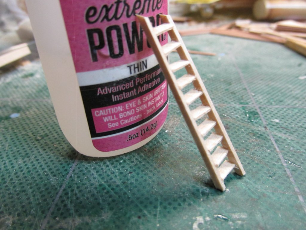
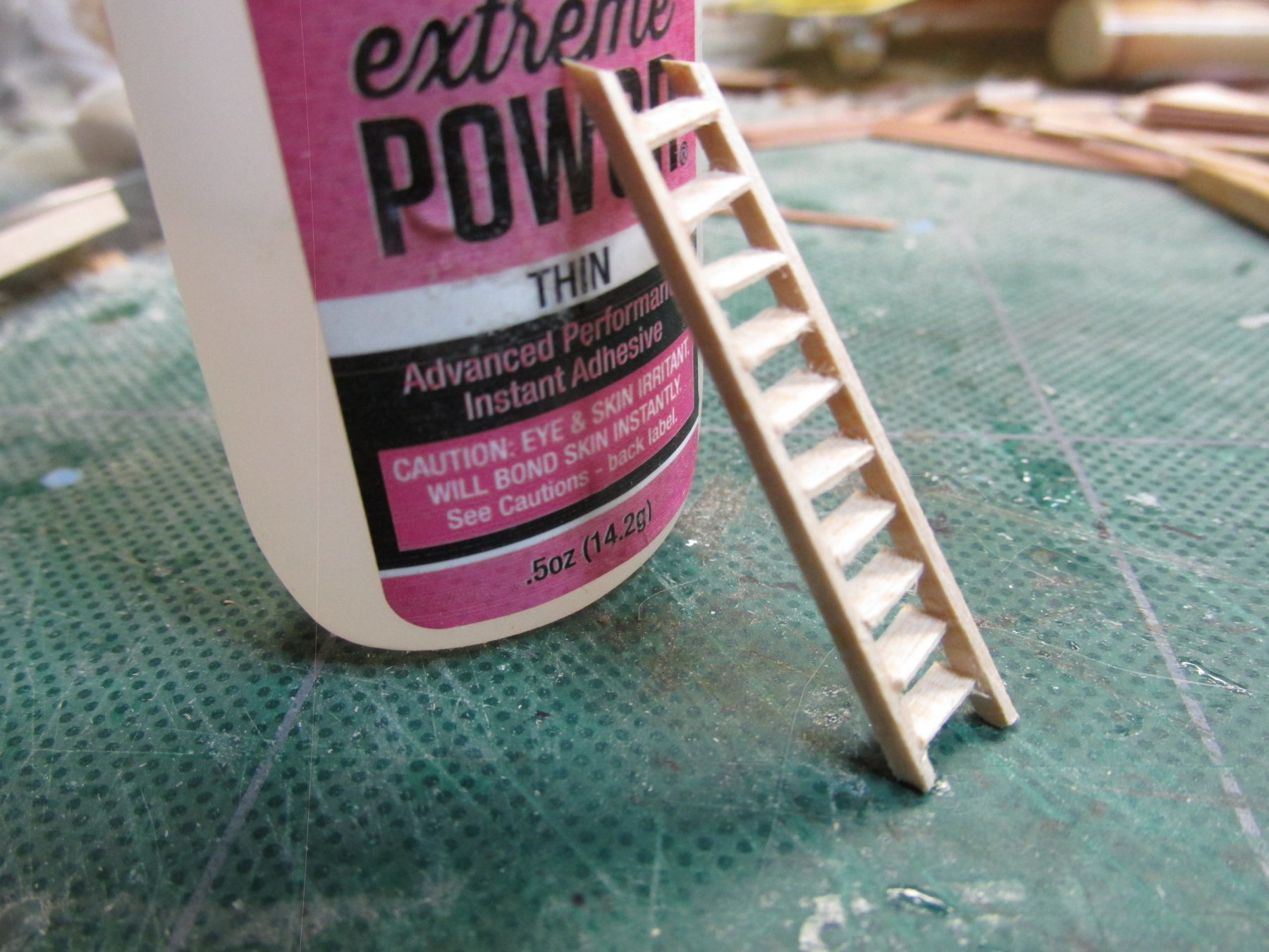
Finally, after waiting about two hours more, I very gingerly slid the ladder out of the jig. The ladder wasn’t perfect. during the gluing process, one of the legs shifted about a millimeter, so the ladder very slightly skewed. It was then given a coat of Wipe-On Poly. This won’t matter much because it will difficult to see. Had this been on the spar deck, I’d do it over. For a first attempt, not too bad.