JSGerson
-
Posts
2,641 -
Joined
-
Last visited
Content Type
Profiles
Forums
Gallery
Events
Everything posted by JSGerson
-
 Following the kit plans, the gunport sides were added. They were cut using my miter saw to create parallelogram shaped pieces to conform to the tumblehome of the hull.
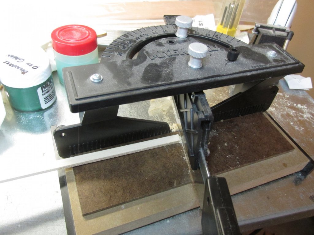
-
Since my last post, I’ve been to Florida to visit Mom for a week and will do so again in June for her 100th birthday. A little celebration, you know the usual stuff: skydiving, a bit of scuba in the Atlantic, a spin in a race car at Daytona, and a wild party in the evening…….Riiiigggght!!! Wishful thinking. Friends and family will drop by to bestow their good wishes, maybe some cake and ice cream. Back at the shipyard, I’ve added the gunport header using the same spacer method.

-
Jim Lad posted April 8, 2013 on Modeller12's Constitution build log, the following: BANYAN added in the same post: I hope this helps Jon
- 742 replies
-
- 6
-

-
- constitution
- frigate
- (and 1 more)
-
I did not mean to burst your bubble. We all make compromises as we construct our builds. We are making models, not necessarily miniature duplicates of the real thing. As you have acknowledged, a model can be as simple or as complicated as we choose to make it. I provided the information to you for your knowledge, not for the observer of the model. You do with it as you see fit. I have yet to see two models of the same ship that are duplicates of each other. That prototype cannonade is a little masterpiece, as you should be proud of it. Keep up the good work. Jon
-
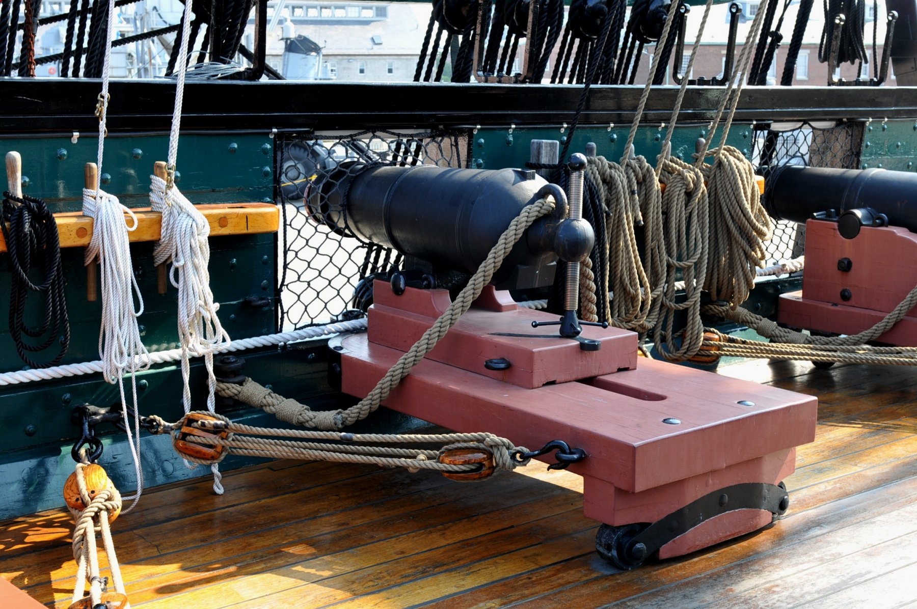
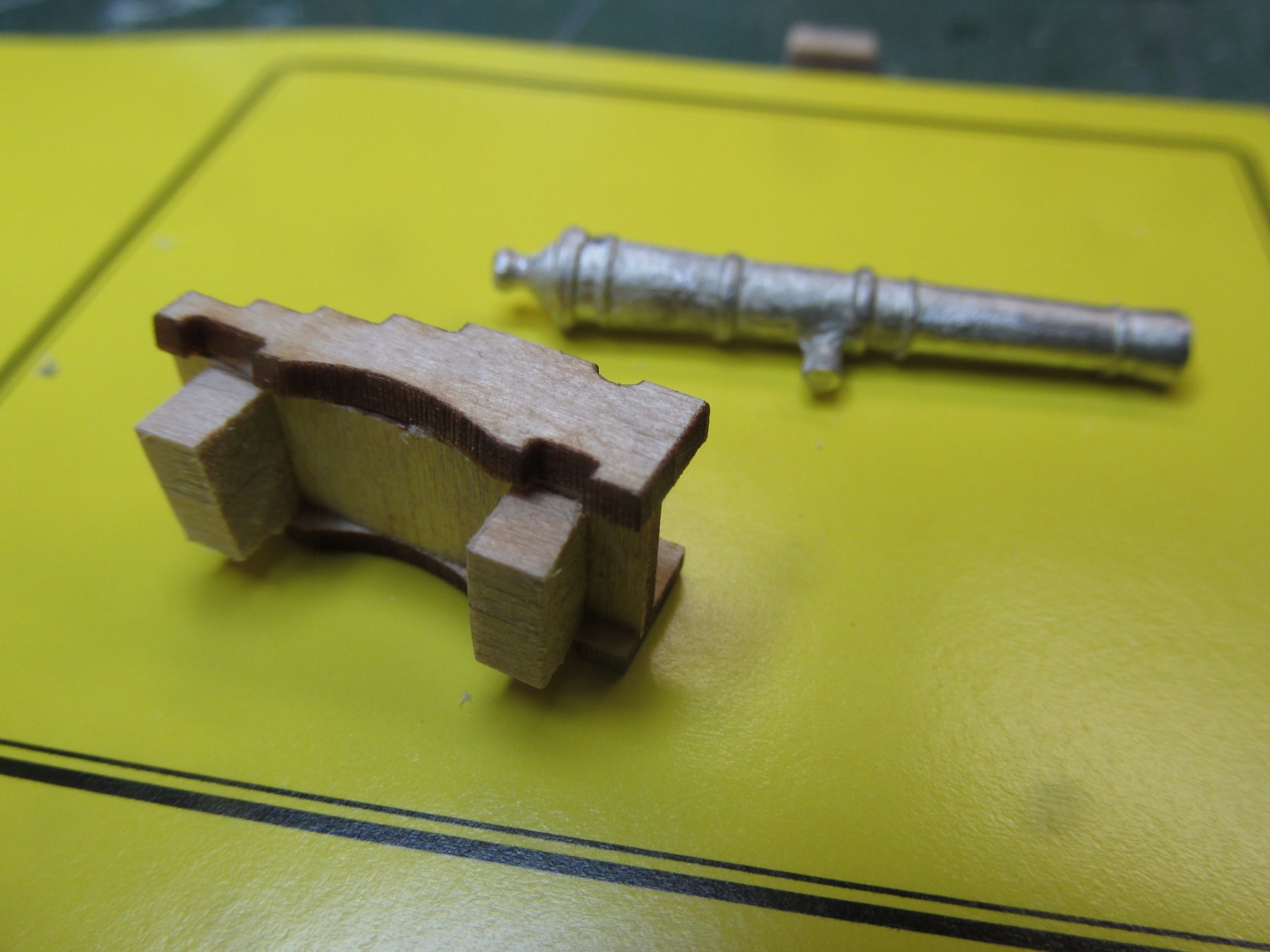
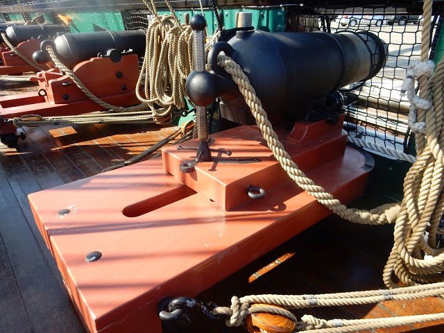
That's a pretty good prototype you built, but if you want to get picky technical, both the image you show of the actual cannonade and thus your prototype, are wrong. I posted this on SawdustDave's build log: Per the USS Constitution Museum’s Restoration Log, “Constitution’s Modern Armament,”: Her first 20th century restoration in 1906-1907 saw fifty-five replica guns made for the ship. All of the present guns were cast for the 1927-1931 restoration with the exception of two 1812-era replica carronades on the after quarter deck. Cast in 1981, these carronades are closer to Constitution‘s 1812 spar deck armament. The gun deck guns were cast in the Charlestown Navy Yard in 1929. The pattern of these guns was based on a British siege gun that was abandoned in Boston during the American Revolution and is currently displayed near Harvard University. The decision to cast “British” guns was made by Lieutenant John A. Lord, Supervisor of the 1927-1931 restoration. He based his decision upon inaccurate research that led the Navy to mistakenly believe that Constitution was outfitted with British guns in 1812. So, thel cannonade with the elevation screw (shown below) is the more accurate version. The choice is yours as the model maker…and mine too when the time comes for me to make the choice.

-
Congratulations! A job well done. Of now you have make a display box, yes?
- 108 replies
-
- 3
-
-
- mamoli
- constitution
- (and 2 more)
-
Never fear, you can never have too many tools. Period. Jon
- 1,354 replies
-
- 4
-
-
- constitution
- model shipways
- (and 1 more)
-
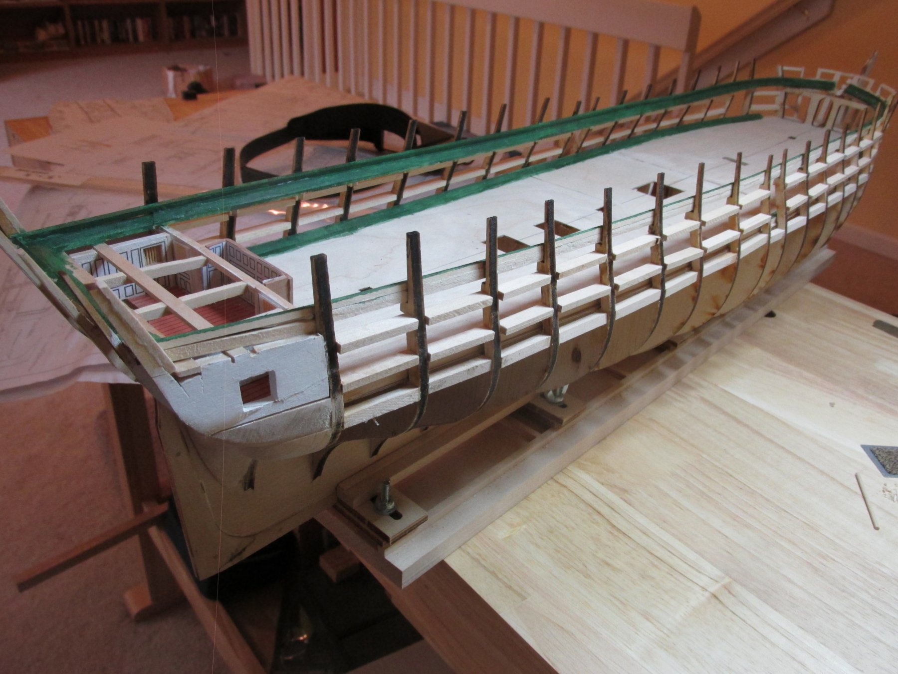
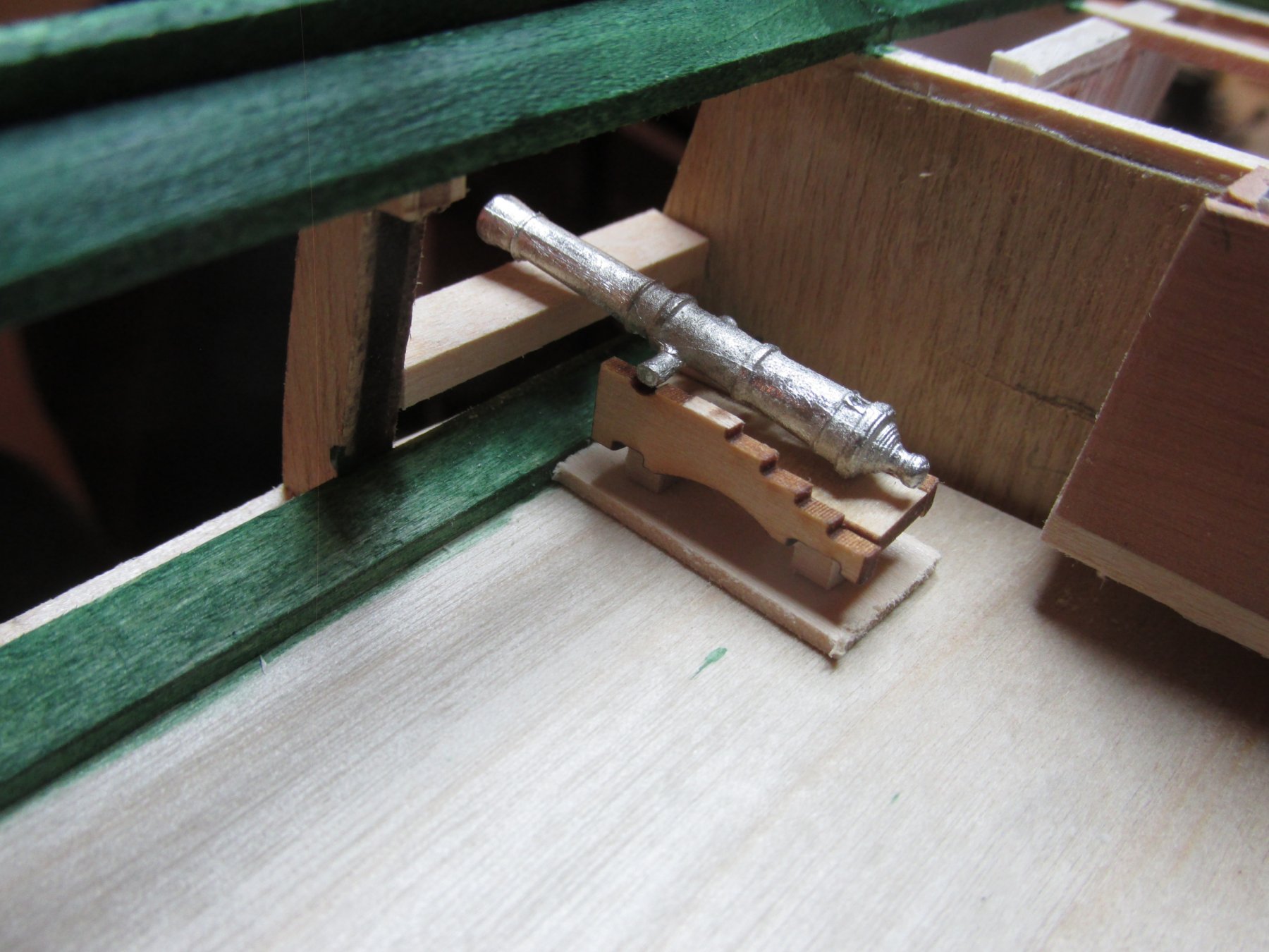
kmart - I thought it was just me, but I think you confirmed it - The guns are too low. After all that measuring, I screwed up again (remember the stern cabin). Thanks for reminding me to look at Usedtosail's build log again. I think he has a good solution - split the gun carriage lengthwise and add a filler piece to raise the height. That's 24 carriages or 48 side pieces plus all the filler strips. There is of course the other possibility of making completely new carriage sides from scratch the way I did for my Rattlesnake. It's a lot of work, but it has to done. Since I can't make the final height measurements until the top header is in place, I think I'll finish the gunport framing. So, based on my "lightening" speed of construction and my planned time off for some other activities next week, it will be a while before I get to those gun carriages. Thanks again Kmart
-
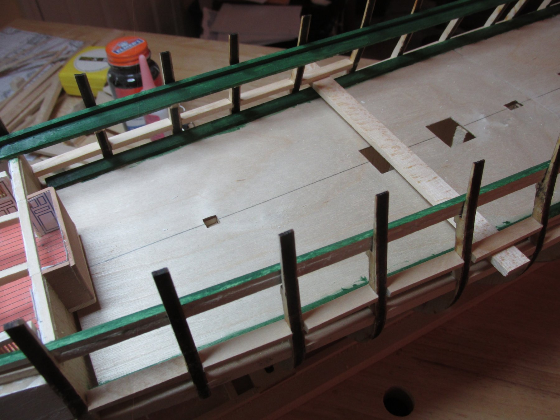
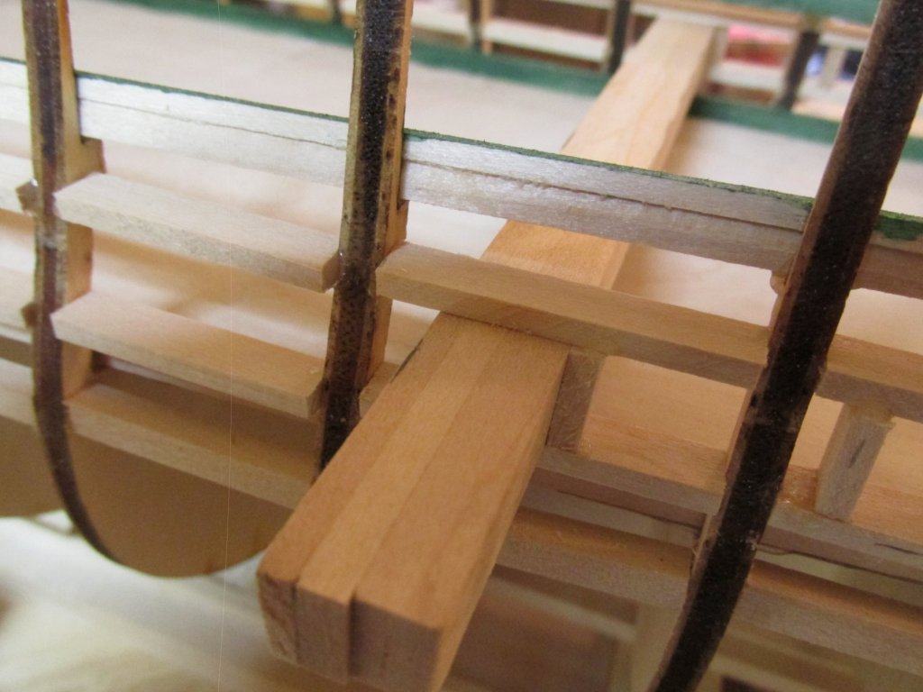
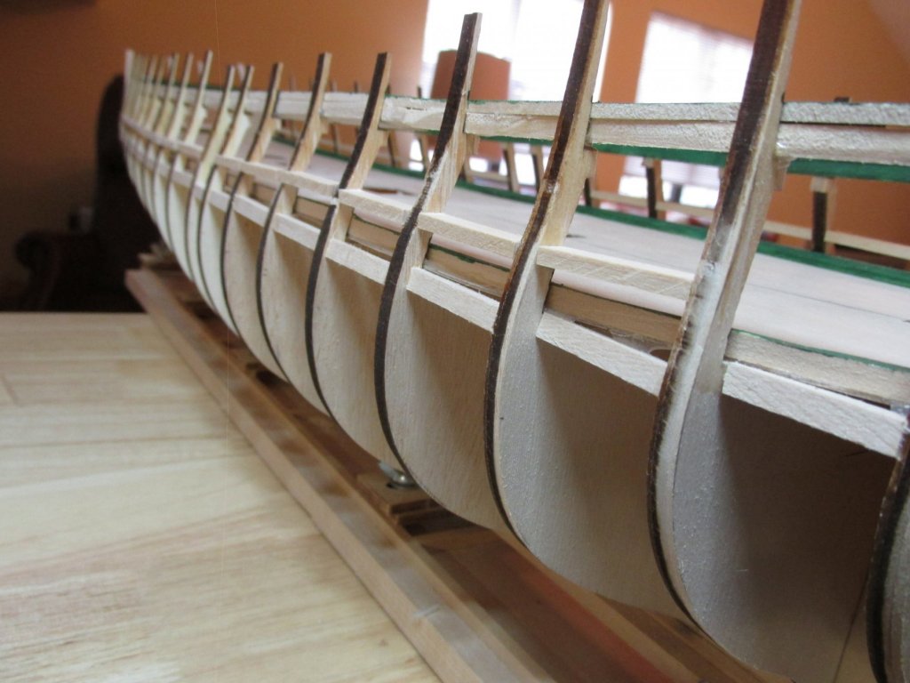
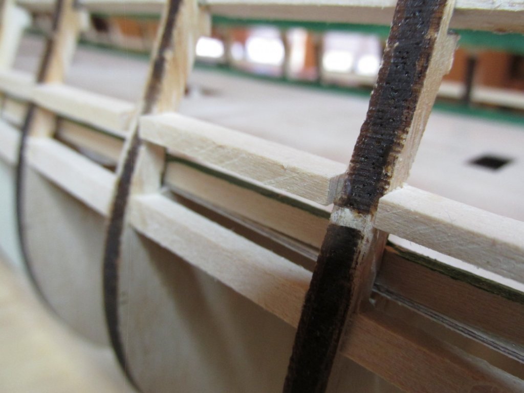
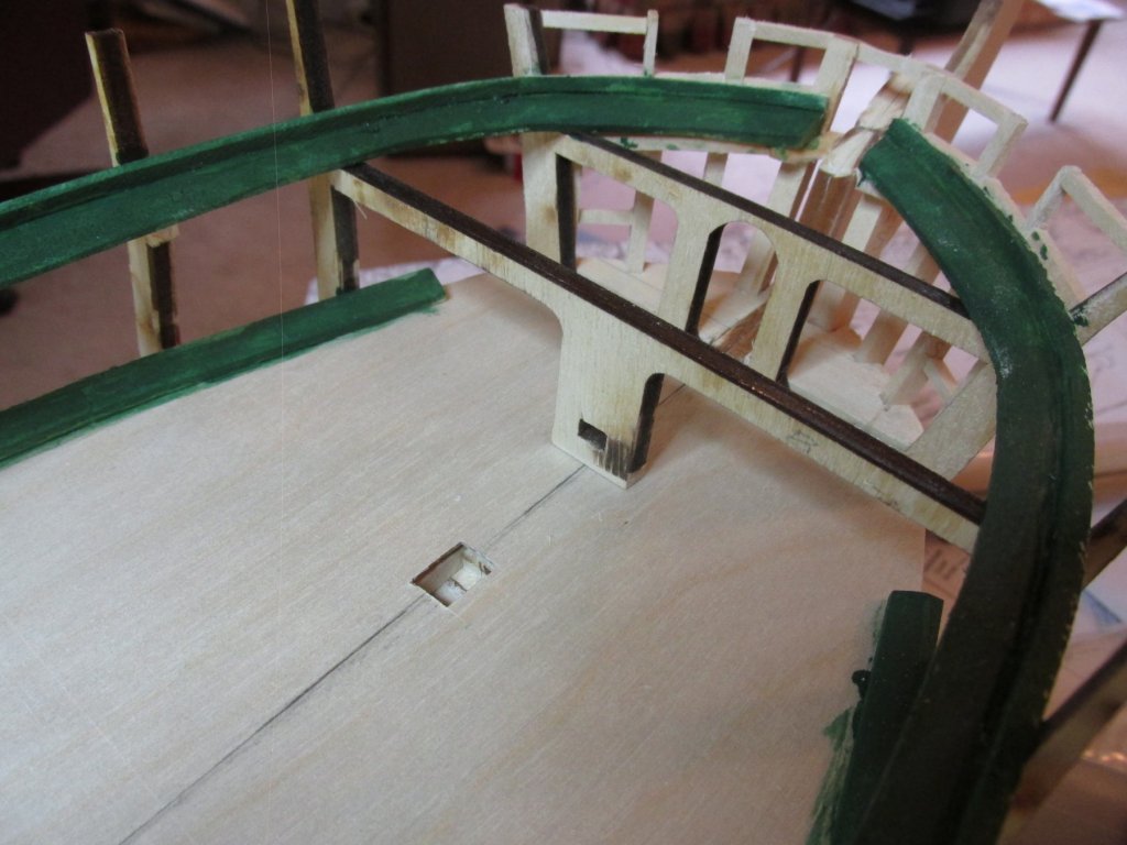
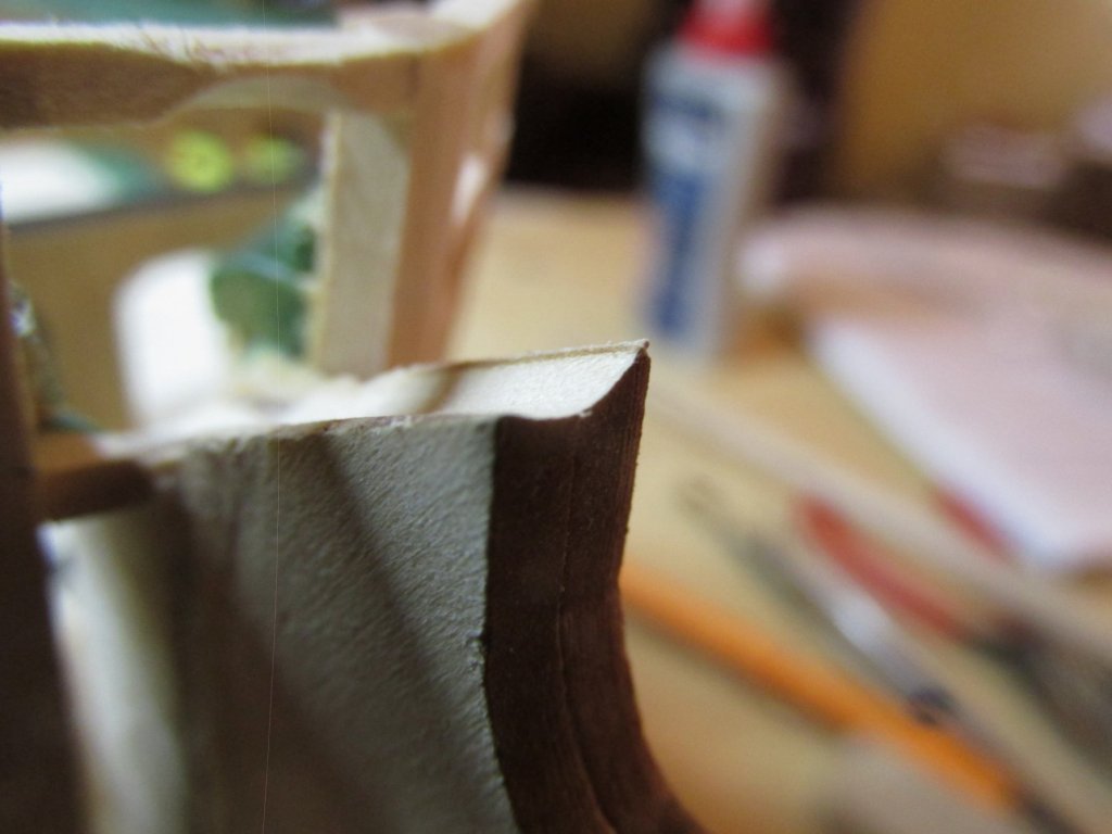
Using the 5/32” thick spacer, which passes through both sides of the model, per kmart, the remaining sills were inserted. As seen looking along the side of the model, the sills correctly follow the curve of the deck. As also seen in the closeup image, excess wood must be trimmed off to bring the sills flush with the hull. I’ve now determined that the first two gunports from the stern and from the stem will use the dummy cannons that came with the kit. That is because I don’t expect these guns to be seen by the observer, plus it will allow me to close those gun port lids so that the observer can see what they look like closed. That’s eight carriage rigs I won’t have to make plus $40 I can keep in my pocket because Model Expo charges $5/cannon & carriage should anyone want to add that gundeck detail. There is one other point I should mention – the sills for those dummy cannons will probably need their width adjusted to accommodate the dummy gun box the kit plans show. Because I plan to close the gunport lids, the muzzle of the cannons will be pulled back, so it only protrudes through the round opening in the closed lids. The kit plans show only the guns in their extended firing position. I don’t know what those measurements will be yet.

-
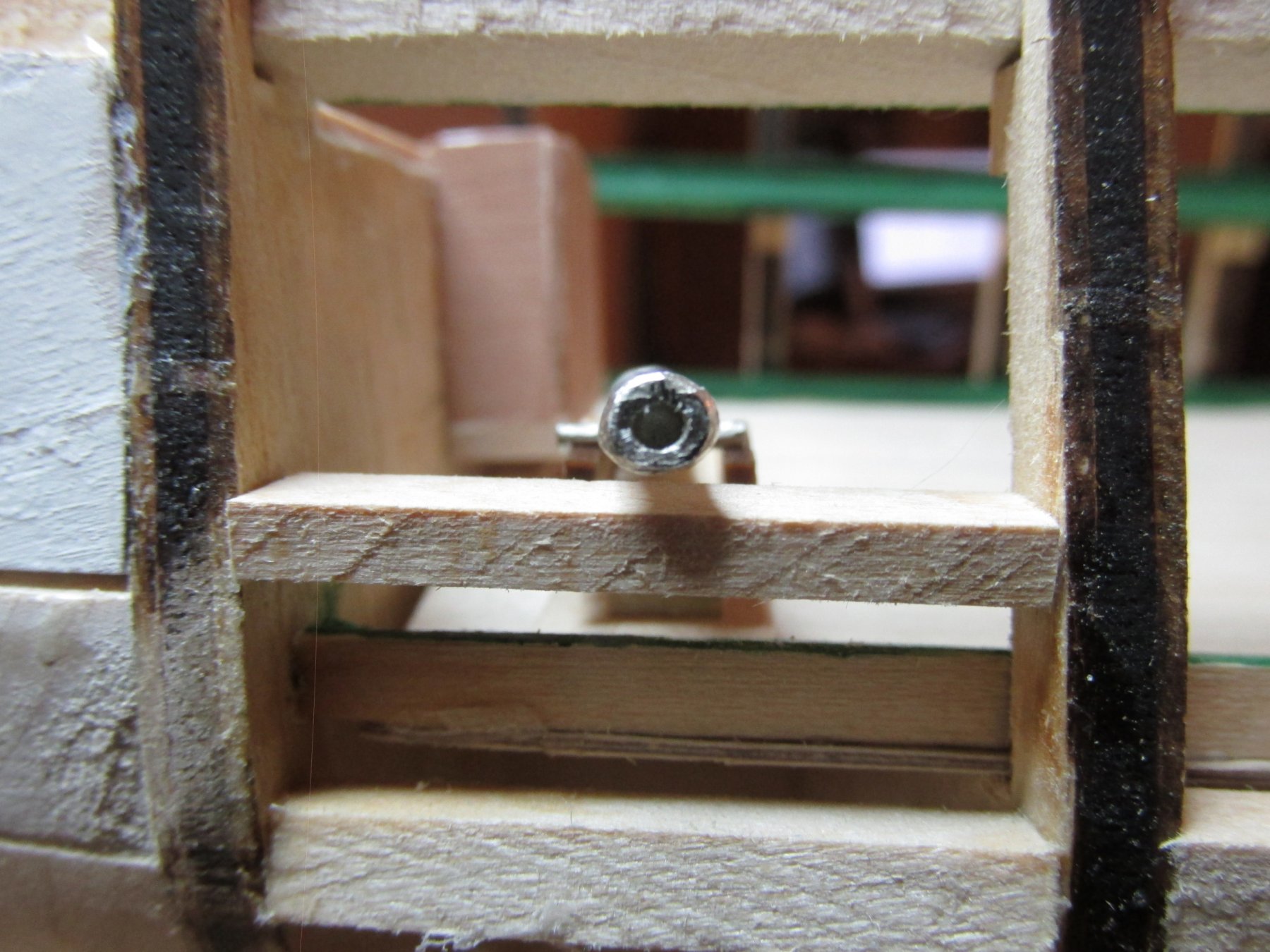
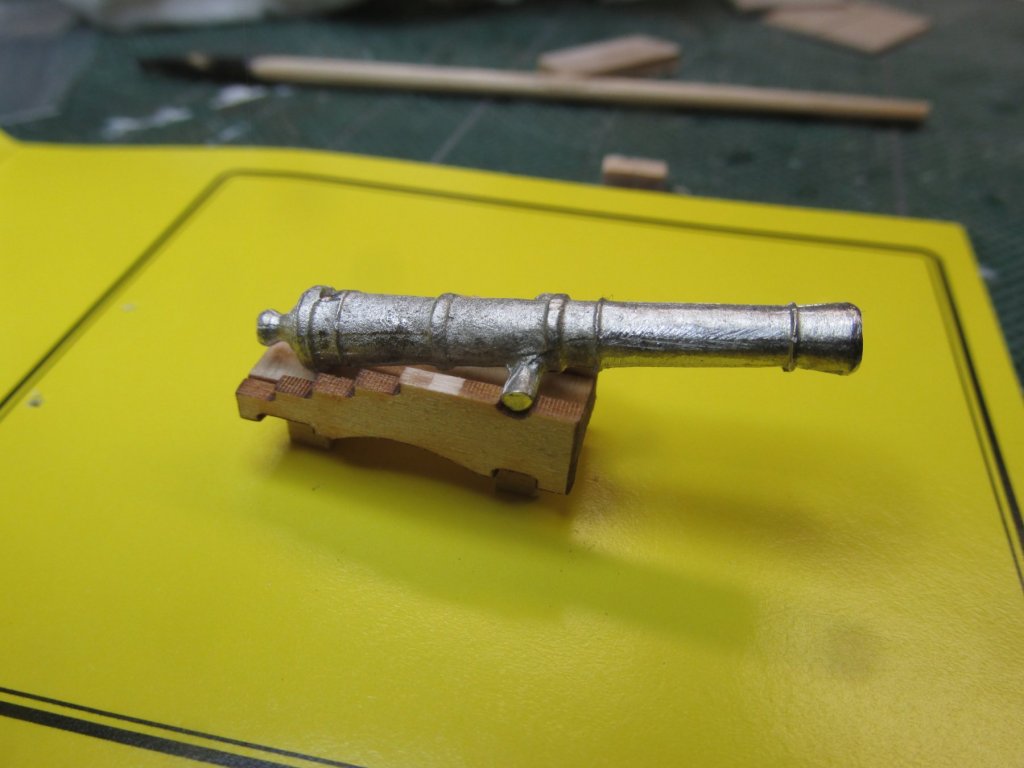
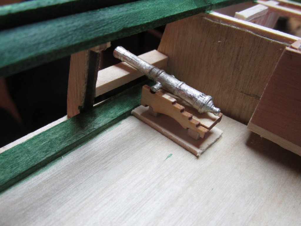
Based on my calculations above, I proceeded to install the first sill using 1/8” x ¼” stock basswood. To verify that those calculations were correct, I put together one long muzzle cannon to act as a gage as briefly mentioned by Darrell earlier. Instead of assembling the axis and wheels for the carriage, I simply used some blocks of equivalent height per kmart’s idea. It’s quick and dirty but does the trick. The mock-up cannon then was placed on a piece of 1/16” thick wood to represent the future planking and then onto the plywood support deck. I think I got it right.


-
She's going to be a beauty when done. I hope you have a place to properly display this "puppy" in your new home because I'm just beginning to realize how big this model is. I have no clue yet where I will display mine. But, I have lots of time to figure that one out at the rate I'm building mine. 8-) Jon
- 1,354 replies
-
- 2
-
-
- constitution
- model shipways
- (and 1 more)
-
Thanks for looking in Darrell. I do plan on making a mock gun assembly as well as a gun port block to frame around. You just be me to the punch in describing them. I was going to talk about those when I got to them. If you go to my Rattlesnake build, you can see my mock gun was made from card stock with an image of the gun pasted on it. Jon
-
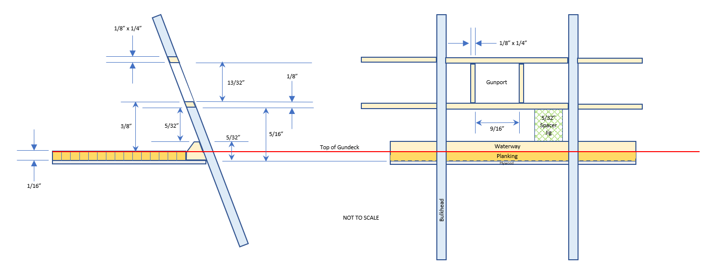
Gundeck Gunport Framing The gundeck gunport framing is more complicated than I thought. At this point I am not following the nice detailed instructions in the practicum because he is not kitbashing the model, so I am constantly second guessing myself. The consistent benchmark from which all measurements originate is “top of gundeck.” However, my “top of gundeck” has not been completely rebuilt yet as the 1/16” decking has not been installed on top of the 1/32” plywood support. The kit plans show that the top edge of the gun port sills is 3/8” from the top of the gundeck. I want to use a spacer block as a jig to ensure all the sills are installed at the same height be having the sills resting on top of the spacer. But because I have installed the gundeck waterway, the spacer must rest on it rather than the plywood. The top of the waterway is 5/32” from the top of the plywood. The top of the spacer goes to the bottom of the sill. Confused yet? I was getting myself lost, so being a visual person, I made a dimensional plan. Now I know (I think) that if I lay a 5/32” thick spacer block on top of the waterway, the sills lieing on top of the spacer, should be at the proper height.

-
You make it look easy...OK, easier than it actually is. I'm just starting the gundeck gun ports myself and I'm glad I have your build log to help guide me. Jon
-
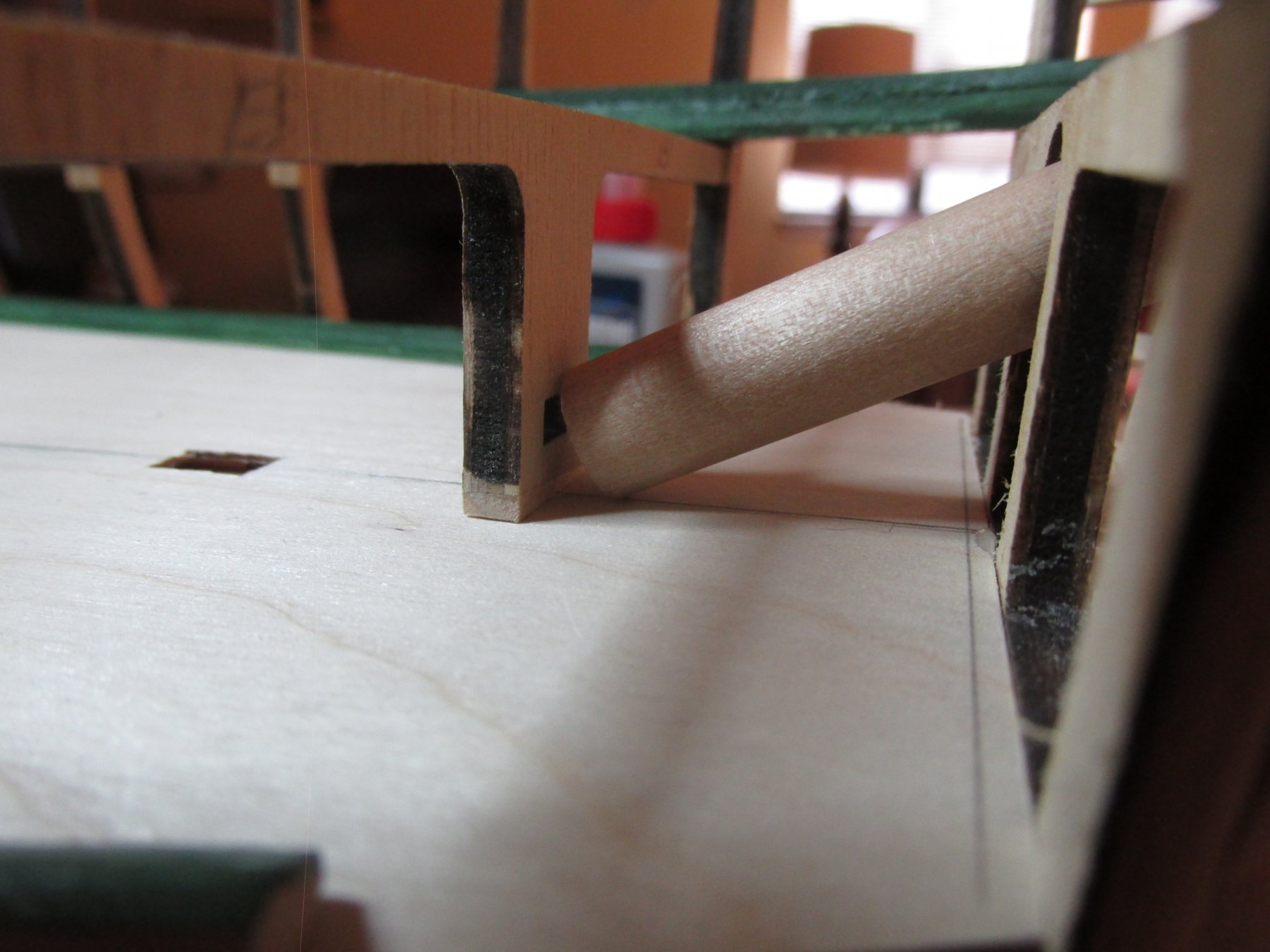
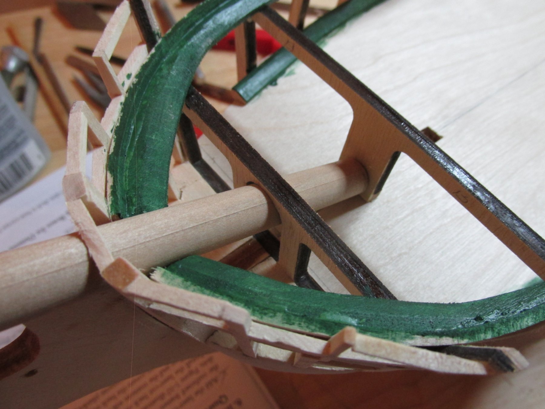
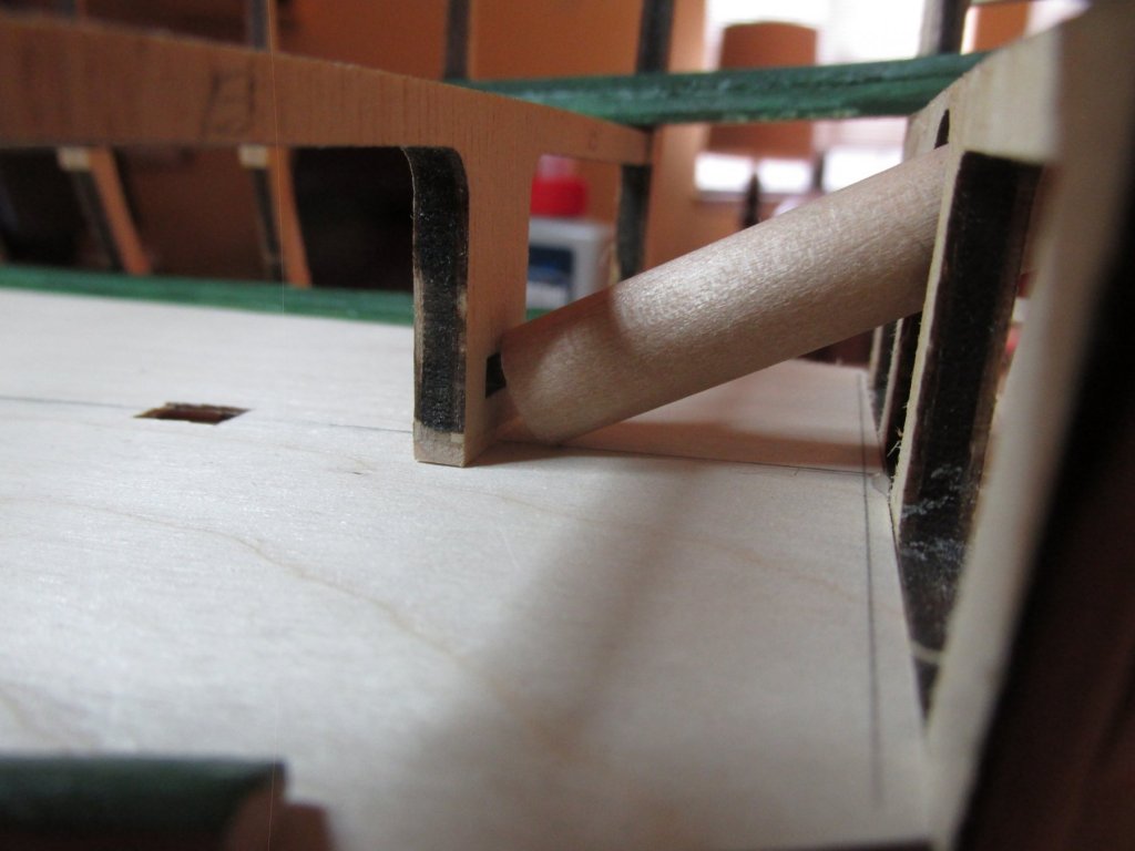
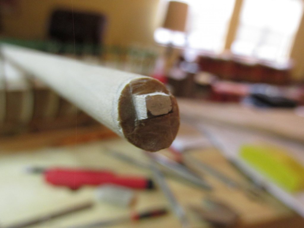
According to the kit plans, the bowsprit rests at angle of 25.5 to the deck°. To my delight, so it is on my model. As you can barely see from my photo below, the dowel that is to become the bowsprit needs to be beveled so it fits flush to the face of bulkhead “B” as well as have a tenon carved into it to fit into the bulkhead “keyhole.” Using my disk sander, I made the bevel. The dowel was then inserted into the bowsprit slot to verify proper fit. Then, with a fine paint brush with a small dab of white paint, a mark was made on the face of the dowel by painting it through the “keyhole” while on the model. The tenon was made with an X-acto knife. And as stated above, because this part of the bulkhead was removable, fitting the parts was relatively easy.

-
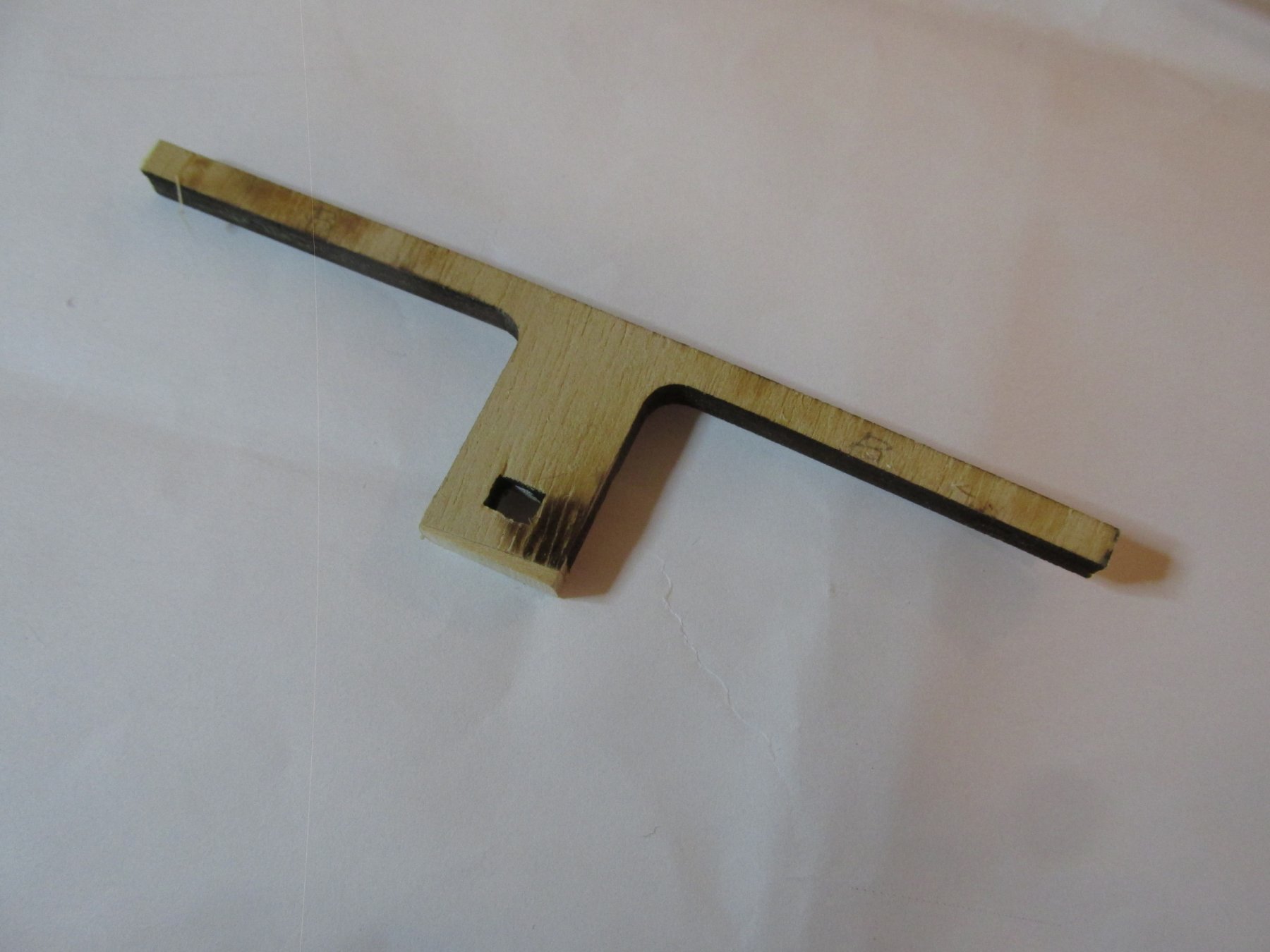
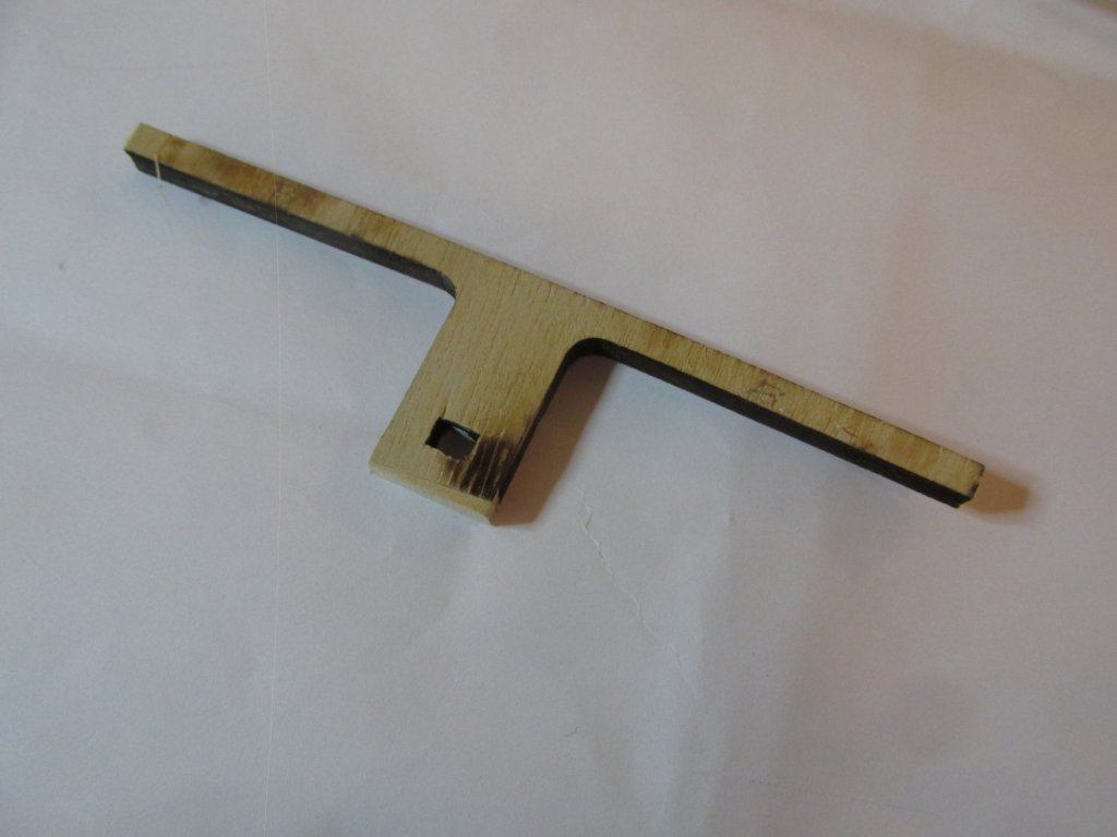
When I did the lobotomy on the bulkheads and keel to create the gun deck, I spliced off that part of bulkhead “B” which had the “keyhole” for the bowsprit to lock into. When I did that at that time, I thought, “Oops, I should not have done that;” but I did not throw that piece away. (If the truth be known, I don’t throw away anything that I think I could use sometime in the future. Luckily(?), I don’t have a significant other, or she would have toss me out 8-). It was fortuitous that I did. It made it a lot easier to fit the bowsprit into it during the carving process. If you look closely at the base of the “T,” there is a wedge of wood I used to level off the part. I had cut the bulkhead off at a slight angle. In addition, due to the waste from the cutting process and the addition of the plywood, the part no longer fit. The wedge corrected both problems. Note, I haven’t decided yet whether to glue the bulkhead back on now or wait till the deck planking is finished. If I wait, the planking will be easier, but I will have trim down the bulkhead again for the 1/16” planks.
-
Fitting the Bowsprit If I were strictly following the practicum, Mr. Hunt would have me plank the spar deck bulwarks “without concern for the locations of the gunports.”The reason for this was as he stated, “Later, when we have framed the gunports out, we will cut the openings through these strips.” I will have to check out the wisdom of this method before I commit to it. So, skipping that section brought me to the last section of Chapter 2 of the practicum, fitting the bowsprit. The first thing that needed to be done was to create a concave surface on the stem for the bowsprit to rest on. A curved file did the trick.
-
On a Side Note… In anticipation of constructing gratings for the gundeck, I contacted Model Expo, the manufacturers of Model Shipways models. They have a guarantee replacement policy for lost, missing, broken, or even builder screwed-up installation parts. My situation was different, I wanted to buy an additional laser cut “Part S” to use for the gundeck. This is the part with all the gratings. I was trying to be honest. I called them on the phone and finally got a hold of “John.” He sounds like a really busy guy because some days he doesn’t answer the phone and you have leave a voice message. He will get back to you…most of the time. I told him I wanted a special order. I wanted to buy a USS Constitution kit part. I guess this was unusual because he had to email someone in order to get a price and would contact me later with it. Three weeks later, after 3 follow-up calls, it turns out that at present, their computer system cannot handle this type of special order. They were in the process of upgrading their system so in the future they could do special orders, but not just now. He then told me to request the part as a free replacement instead, which I did. I offered to buy the part and pay shipping which they couldn’t do (?), but a free replacement, no problem, go figure. It’s been 3 days since I requested the “replacement” part…we’ll see what happens.
-
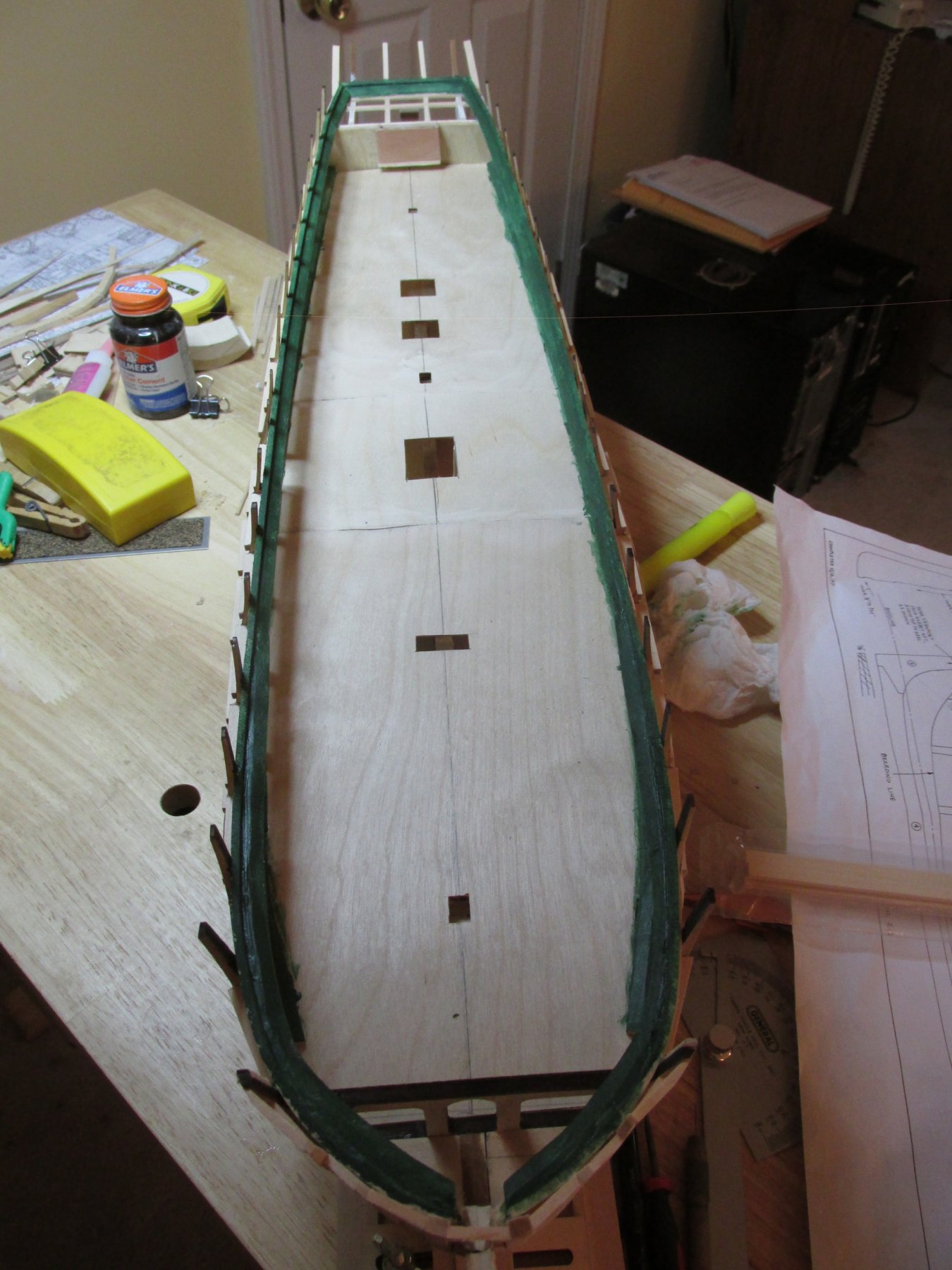
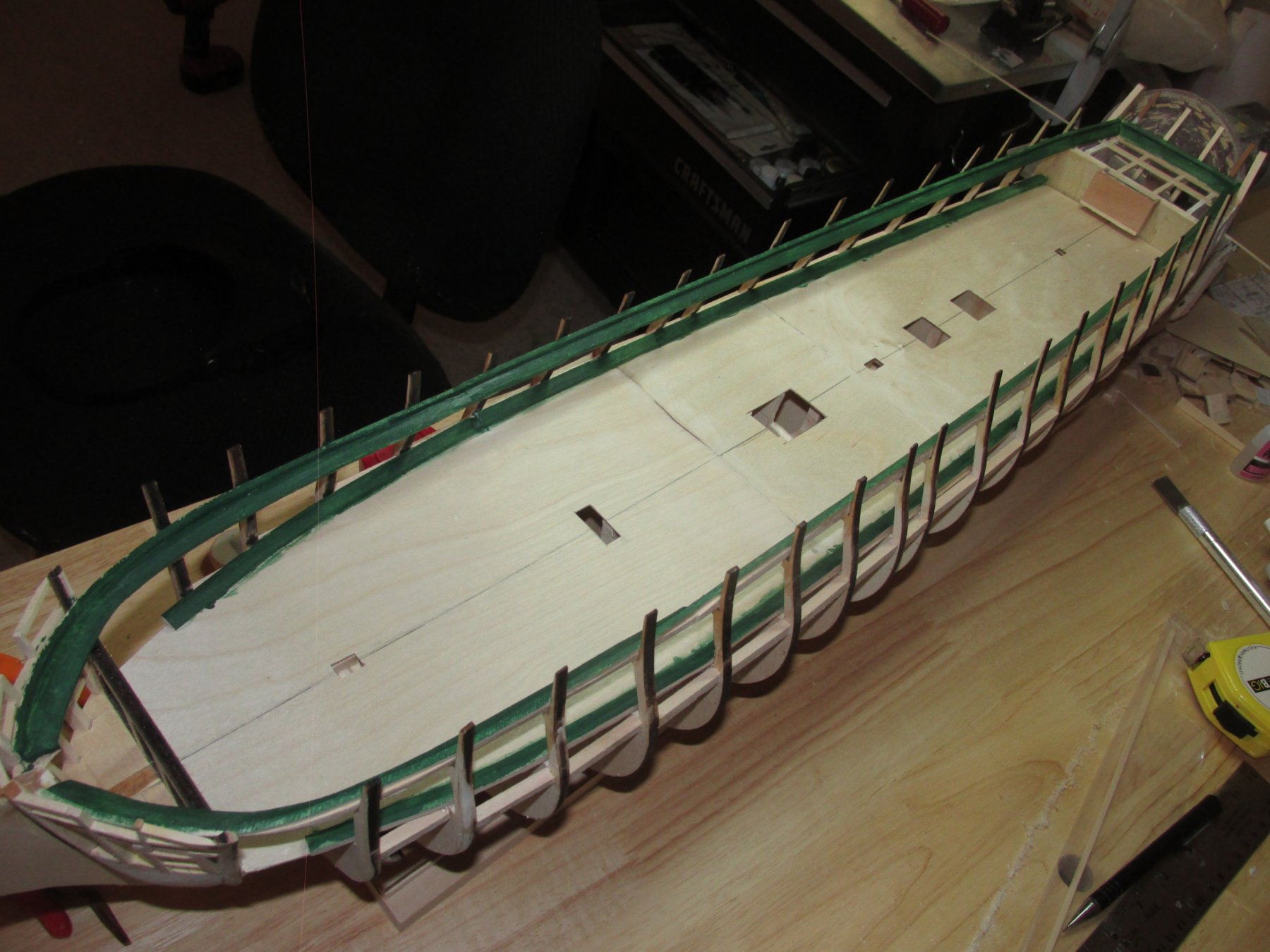
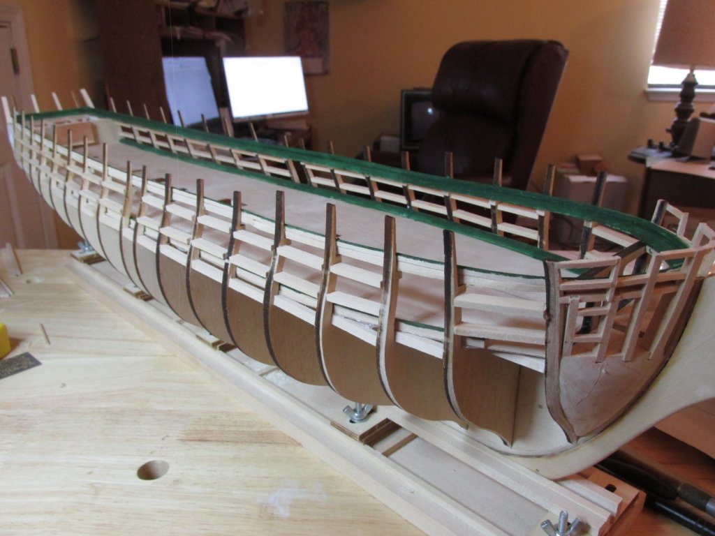
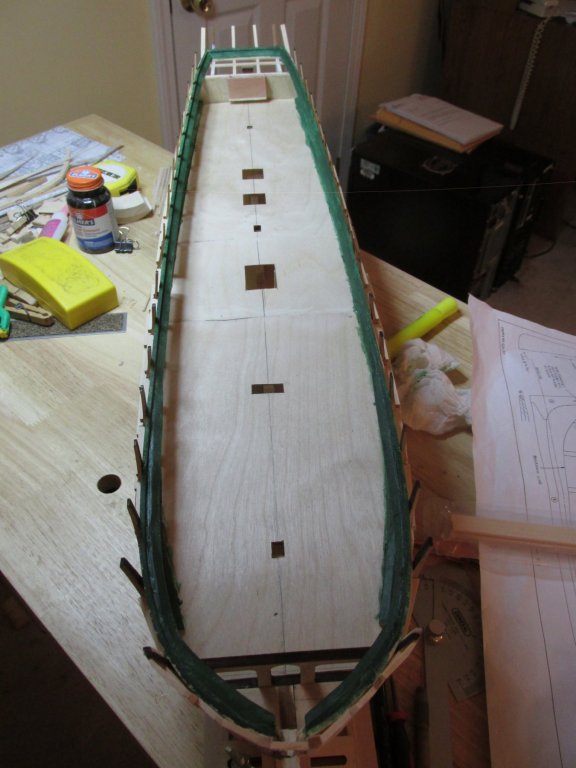
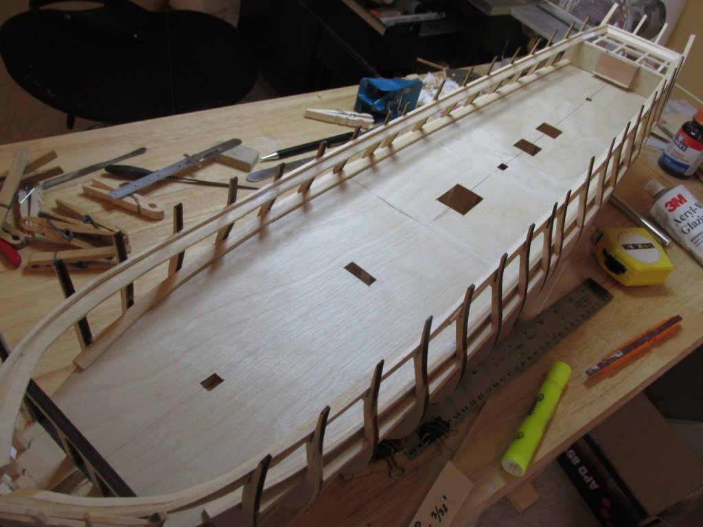
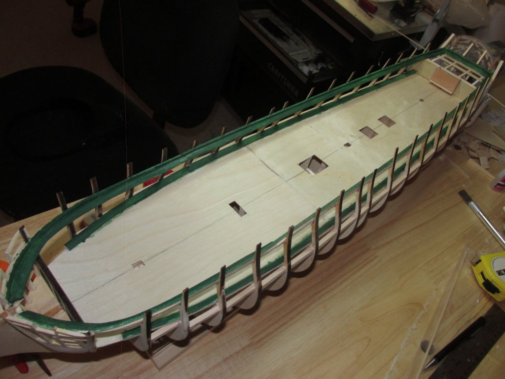
The gundeck waterway was installed in two pieces like the spar deck only it falls short of the bow. That portion of the gun deck won’t be seen. This made it easier to bend the waterway. A little touch-up with glazing putty and sanding at the waterway joints, and the they were painted green. It’s much easier to paint them now than later.
-
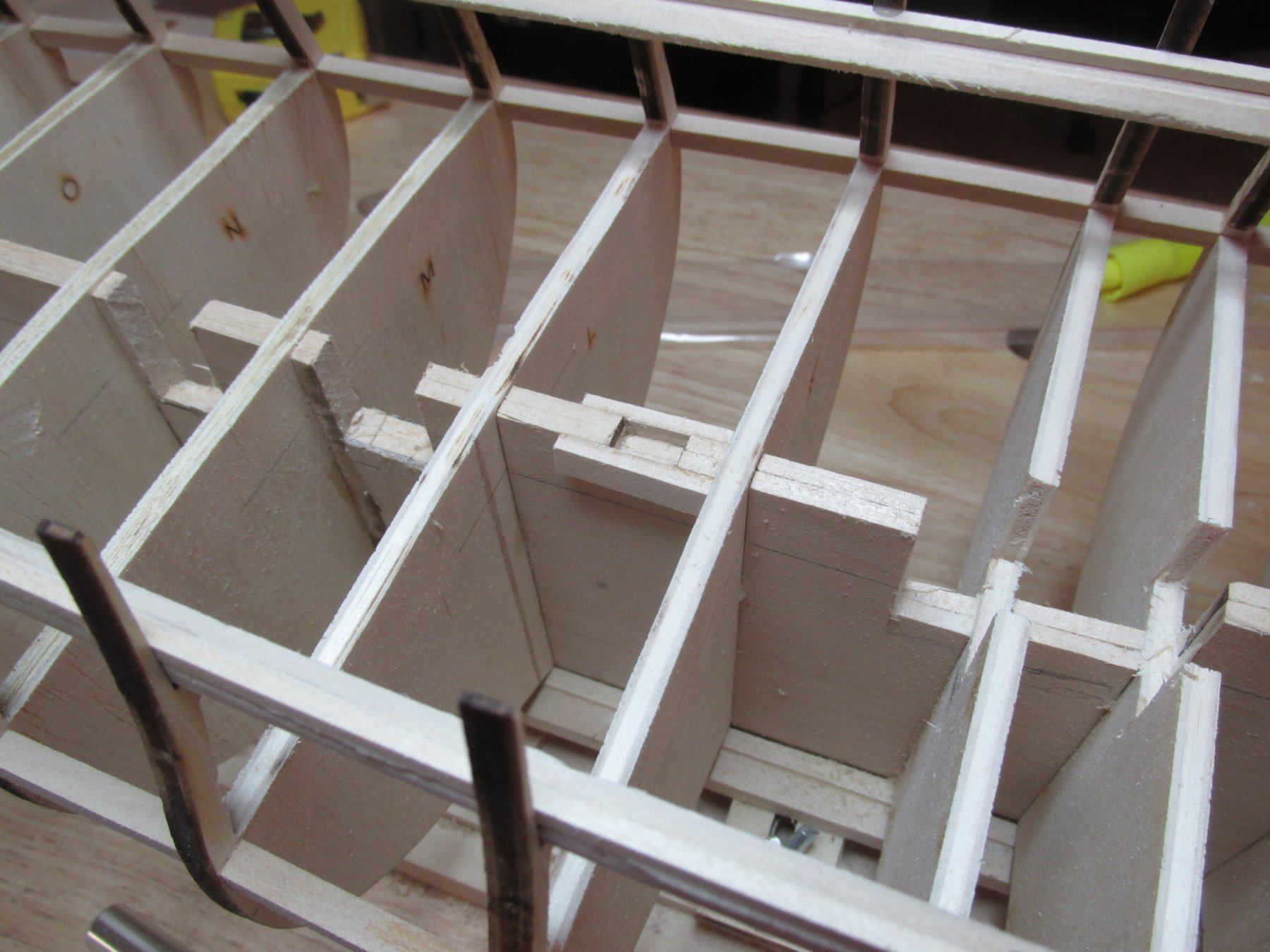
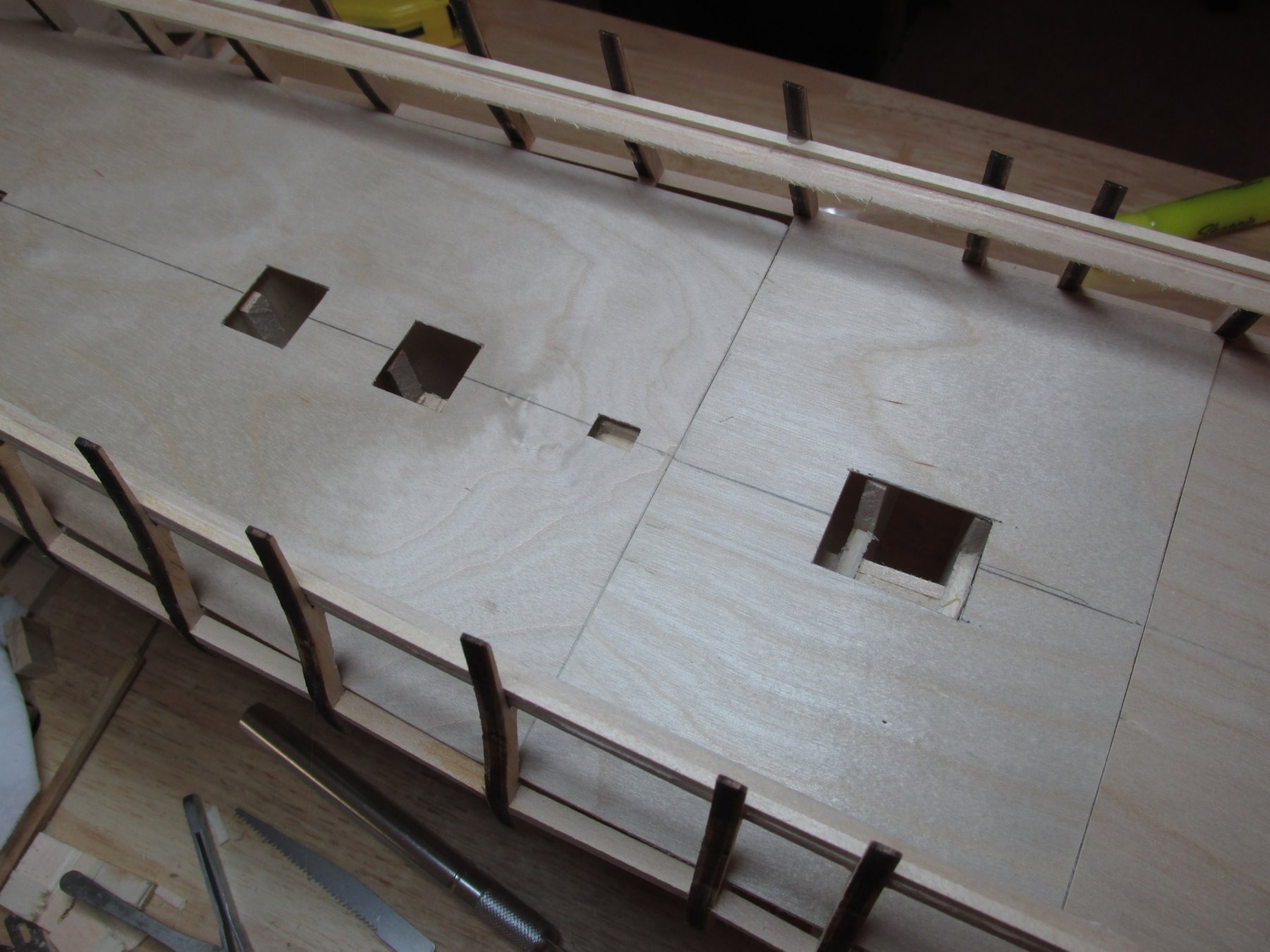
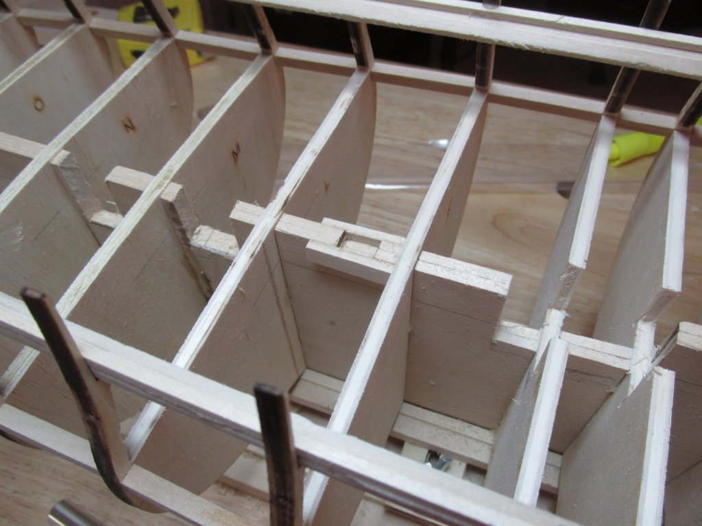
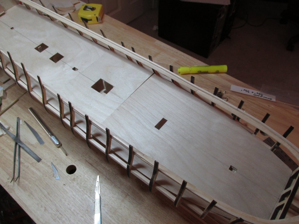
I determined which and where the openings in the gundeck were to be, measured for their locations and cut them out of the plywood gundeck support pieces. Not only did the support needed to be cut, but areas of the keel and certain bulkheads under them had to be modified to allow the installation of ladders. The support pieces were placed back onto the model, so I could mark where the keel and affected bulkheads needed to be cut. I figured that approximately 1” in depth needed to be removed to give the illusion of the berthing deck below. I thought about just painting those areas black, but if light hit those spots wrong, the bulkheads and keel might be visible, and the illusion would be lost. Images below were taken just before the plywood was glued down.

-
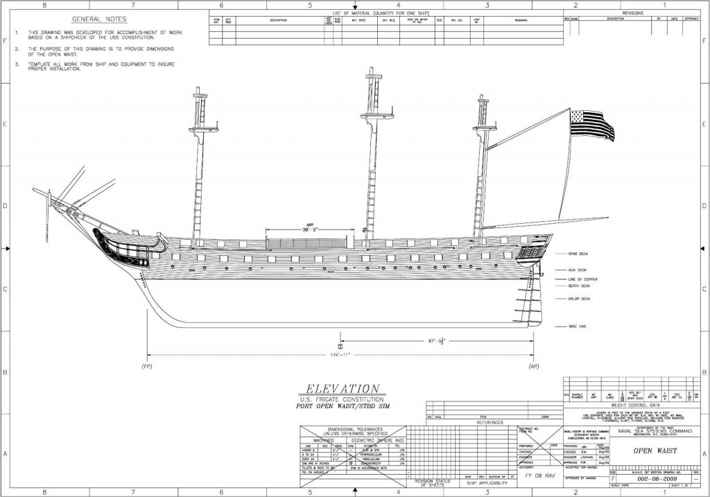
My two cents about the open waist. Here is the US Navy plan for the open waist dated August 2009.
- 742 replies
-
- 7
-
-
- constitution
- frigate
- (and 1 more)
-
Very nice pictures. I've added them to my reference library. The gun deck is looking great too. Jon
-
I'm amazed you even attempted those carvings, let alone succeeded in pulling it off! Well done!
- 742 replies
-
- 8
-
-
- constitution
- frigate
- (and 1 more)
-
Welcome to my build Bill, pull up a comfortable chair because anyone who has followed my builds, knows that I am sssssslllooowww. The practicum I am using as a guide was written by Robert Hunt and can be purchased ($100 plus $60 for the rigging instructions) on his site Lauck Street Shipyard. I bought mine as a bargain sale. If you are new to ship building or have limited experience, or just plain intimidated, his practicums should help you. They are not perfect, but without his document, I could not have started my Rattlesnake, let alone build it. If you follow his instructions, you will get a nice model. If you use his practicum as a guide and use the wisdom of the build logs on this site, you will get a superb model. Jon
-
The simple answer to your question kmart, about percent scaling of the US Navy plans to fit the 76.8 scale of the kit is…I don’t know. For the complex answer, I need to explain. In order to reduce the size of the gun deck plans, I used my super sophisticated CAD program, MS PowerPoint. I don’t have a real CAD program or any “Photoshop” type software. The first thing I did was import the plans images (two separate images) into PowerPoint and align and group them into one complete image. So now the fateful question arises, how small do I reduce the plan image? I needed something on my model that I could measure and in turn measure on the Gun Deck plan. I chose the distance between the Main Mast and the Foremast. I believe that was about 12” or so. Along the edges of the PowerPoint work space are rulers, one vertical and the other horizontal. Using the horizontal PowerPoint ruler, I reduced and positioned the image so that the mast separation reflected the distance I measure on the model. To print the plan, the image had to be in 3 positions, so the print area covered the complete image. The 3 prints, each with a portion of the complete plan, were then aligned, taped together, and trimmed to fit onto the model. It was then that I discovered that the PowerPoint ruler was inaccurate, the printed mast positions did not match the model. Since the built-in PowerPoint ruler left something to be desired, I made my own I knew the distance between the mast as 12” so I drew a line in PowerPoint between the masts in the image, added 13 tick marks of equal spacing to create the ruler and printed it, and compared it with an actual ruler, made adjustments as necessary and printed again. After about 4 or 5 tries of readjusting the image size by trial and error, I got a match. Now with the accurate PowerPoint ruler to measure the mast separation, I adjusted the plan size and voila, a perfect template.