


JSGerson
-
Posts
2,171 -
Joined
-
Last visited
Reputation Activity
-

 JSGerson got a reaction from Prowler901 in USS Constitution by JSGerson - Model Shipways Kit No. MS2040
Now it’s time to install the rail supports. These are positioned such that the joints of the floor grating in the seats of ease area, rest on the horizontal structural beams attached to the rail supports. In other words. Where the gratings meet, that is where the rail support is supposed to be. Using the grating parts supplied in the MS kit, I taped the three pieces together that make up most of the flooring, to mark off where the joints are with the architect tape on the stem.
-

 JSGerson got a reaction from Der Alte Rentner in Rattlesnake by JSGerson - FINISHED - Mamoli - 1:64 - Using Robert Hunt’s practicum
FINISHED
Well here they are, the last planned official images of my Rattlesnake, safe and snug in her case. For those who followed my loooonnnnnng and s l o w build over the past seven years, once again, thank you for being so patient and thank you for all the “likes.”
-
 JSGerson got a reaction from KurtH in USS Constitution by JSGerson - Model Shipways Kit No. MS2040
Now it’s time to install the rail supports. These are positioned such that the joints of the floor grating in the seats of ease area, rest on the horizontal structural beams attached to the rail supports. In other words. Where the gratings meet, that is where the rail support is supposed to be. Using the grating parts supplied in the MS kit, I taped the three pieces together that make up most of the flooring, to mark off where the joints are with the architect tape on the stem.
-
JSGerson got a reaction from Prowler901 in USS Constitution by JSGerson - Model Shipways Kit No. MS2040
This is when I discover a new problem. According to the MS plans, the precut gammoning holes in the stem are supposed to be between supports Nos. 2 and 3. Per the marks I just made with the gratings, the gammoning holes straddle rail support No. 3. The gammoning holes are where the gammoning chains pass through. Looking at the US Navy 1927 -31 Restoration plan No. 24779, the gammoning holes have been replaced with eye bolts embedded into the stem. The gammoning chains are then connected to the eye bolts. The chains are fastened to the bowsprit in the same manner as shown in the MS plans. These stem bolts are positioned half the distances apart as the pre-cut holes are and appear to be straddling rail support No. 3 from the numerous photos that I’ve looked at. Based on the all the ambiguities, just about nobody will even know about or bother to look inside the rails supports to see if there is even any gammoning there, let alone whether it is correct or not. Therefore, I am going to use the existing gammoning holes as they exist on my model in lieu of the embedded bolts shown on the US Navy plans, just because as builder of the model, I like the way they look.
-
JSGerson got a reaction from Prowler901 in USS Constitution by JSGerson - Model Shipways Kit No. MS2040
As I mentioned in an earlier posting, the MS plan drawings of the rail supports do not fit properly on my model. Whether I’m at fault or the plans are, is immaterial. These have to be custom made now., By trial and error measuring using card stock, a first try template was drawn and cut out of the cardstock. Once I got the card stock to fit, it was traced onto 1/8” thick stock wood. Once I got the wooden piece to fit, I realized that it had to be refined a bit more. A second wood rail support was fabricated. This was able to fit properly onto the rails. The support was removed, painted and pin striped. Finally, it was installed. This was repeated the same manner (with or without an extra preliminary wood support as needed) for the remaining nine supports.
-
JSGerson got a reaction from KurtH in USS Constitution by JSGerson - Model Shipways Kit No. MS2040
This is when I discover a new problem. According to the MS plans, the precut gammoning holes in the stem are supposed to be between supports Nos. 2 and 3. Per the marks I just made with the gratings, the gammoning holes straddle rail support No. 3. The gammoning holes are where the gammoning chains pass through. Looking at the US Navy 1927 -31 Restoration plan No. 24779, the gammoning holes have been replaced with eye bolts embedded into the stem. The gammoning chains are then connected to the eye bolts. The chains are fastened to the bowsprit in the same manner as shown in the MS plans. These stem bolts are positioned half the distances apart as the pre-cut holes are and appear to be straddling rail support No. 3 from the numerous photos that I’ve looked at. Based on the all the ambiguities, just about nobody will even know about or bother to look inside the rails supports to see if there is even any gammoning there, let alone whether it is correct or not. Therefore, I am going to use the existing gammoning holes as they exist on my model in lieu of the embedded bolts shown on the US Navy plans, just because as builder of the model, I like the way they look.
-
 JSGerson got a reaction from Snug Harbor Johnny in USS Constitution by JSGerson - Model Shipways Kit No. MS2040
BTY, I’m not knocking Mr. Hunt’s practicum. I could not have gotten this far if it weren’t for it. But I have learned that he’s human and he's the first to admit that his way may not be the best which is why in addition to using his practicum as a guide (not my bible), I also check how other builders solve these problems.
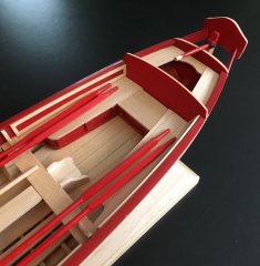
My second fabrication attempt at the 2nd rails went relatively smoothly; and they were glued into placed. In the first image below, I attempted to show the slight curve in the rails.
-
 JSGerson got a reaction from Tigersteve in USS Constitution by JSGerson - Model Shipways Kit No. MS2040
As I mentioned in an earlier posting, the MS plan drawings of the rail supports do not fit properly on my model. Whether I’m at fault or the plans are, is immaterial. These have to be custom made now., By trial and error measuring using card stock, a first try template was drawn and cut out of the cardstock. Once I got the card stock to fit, it was traced onto 1/8” thick stock wood. Once I got the wooden piece to fit, I realized that it had to be refined a bit more. A second wood rail support was fabricated. This was able to fit properly onto the rails. The support was removed, painted and pin striped. Finally, it was installed. This was repeated the same manner (with or without an extra preliminary wood support as needed) for the remaining nine supports.
-
 JSGerson got a reaction from etubino in USS Constitution by JSGerson - Model Shipways Kit No. MS2040
This is when I discover a new problem. According to the MS plans, the precut gammoning holes in the stem are supposed to be between supports Nos. 2 and 3. Per the marks I just made with the gratings, the gammoning holes straddle rail support No. 3. The gammoning holes are where the gammoning chains pass through. Looking at the US Navy 1927 -31 Restoration plan No. 24779, the gammoning holes have been replaced with eye bolts embedded into the stem. The gammoning chains are then connected to the eye bolts. The chains are fastened to the bowsprit in the same manner as shown in the MS plans. These stem bolts are positioned half the distances apart as the pre-cut holes are and appear to be straddling rail support No. 3 from the numerous photos that I’ve looked at. Based on the all the ambiguities, just about nobody will even know about or bother to look inside the rails supports to see if there is even any gammoning there, let alone whether it is correct or not. Therefore, I am going to use the existing gammoning holes as they exist on my model in lieu of the embedded bolts shown on the US Navy plans, just because as builder of the model, I like the way they look.
-
 JSGerson got a reaction from Ryland Craze in USS Constitution by JSGerson - Model Shipways Kit No. MS2040
Now it’s time to install the rail supports. These are positioned such that the joints of the floor grating in the seats of ease area, rest on the horizontal structural beams attached to the rail supports. In other words. Where the gratings meet, that is where the rail support is supposed to be. Using the grating parts supplied in the MS kit, I taped the three pieces together that make up most of the flooring, to mark off where the joints are with the architect tape on the stem.
-
JSGerson got a reaction from Ryland Craze in USS Constitution by JSGerson - Model Shipways Kit No. MS2040
As I mentioned in an earlier posting, the MS plan drawings of the rail supports do not fit properly on my model. Whether I’m at fault or the plans are, is immaterial. These have to be custom made now., By trial and error measuring using card stock, a first try template was drawn and cut out of the cardstock. Once I got the card stock to fit, it was traced onto 1/8” thick stock wood. Once I got the wooden piece to fit, I realized that it had to be refined a bit more. A second wood rail support was fabricated. This was able to fit properly onto the rails. The support was removed, painted and pin striped. Finally, it was installed. This was repeated the same manner (with or without an extra preliminary wood support as needed) for the remaining nine supports.
-
JSGerson got a reaction from Ryland Craze in USS Constitution by JSGerson - Model Shipways Kit No. MS2040
This is when I discover a new problem. According to the MS plans, the precut gammoning holes in the stem are supposed to be between supports Nos. 2 and 3. Per the marks I just made with the gratings, the gammoning holes straddle rail support No. 3. The gammoning holes are where the gammoning chains pass through. Looking at the US Navy 1927 -31 Restoration plan No. 24779, the gammoning holes have been replaced with eye bolts embedded into the stem. The gammoning chains are then connected to the eye bolts. The chains are fastened to the bowsprit in the same manner as shown in the MS plans. These stem bolts are positioned half the distances apart as the pre-cut holes are and appear to be straddling rail support No. 3 from the numerous photos that I’ve looked at. Based on the all the ambiguities, just about nobody will even know about or bother to look inside the rails supports to see if there is even any gammoning there, let alone whether it is correct or not. Therefore, I am going to use the existing gammoning holes as they exist on my model in lieu of the embedded bolts shown on the US Navy plans, just because as builder of the model, I like the way they look.
-
 JSGerson got a reaction from Stevenleehills in USS Constitution by JSGerson - Model Shipways Kit No. MS2040
Now it’s time to install the rail supports. These are positioned such that the joints of the floor grating in the seats of ease area, rest on the horizontal structural beams attached to the rail supports. In other words. Where the gratings meet, that is where the rail support is supposed to be. Using the grating parts supplied in the MS kit, I taped the three pieces together that make up most of the flooring, to mark off where the joints are with the architect tape on the stem.
-
 JSGerson got a reaction from Scallywag in USS Constitution by JSGerson - Model Shipways Kit No. MS2040
The practicum uses a coppering method which I feel could use a little improvement. Mr. Hunt used a ponce wheel to make plate edge dimples on the copper plate edge. Unfortunately, I feel they are oversized for the scale and look more like a boilerplate. A lot of builders used this method of just outlining the plate, and some made them with bumps raising above the plate like rivets. But after seeing actual pictures of the Constitution’s plating, I going to attempt an alternative method of embossed plates.
According to Roger Frye’s Shop Notes in the Nautical Research Journal V66-4 Winter 2021:
Per the quote above, the range between 1:96 scale and the Model Shipways kit at 1:76.8 scale, is left to the judgement and skills of the builder. The plate nails make small minor depressions so the indentations will have to be almost flat, just enough to disrupt the natural smooth mirror finish of the copper tape that is provided in the kit. The first image below is what Mr. Hunt created. The following images are of the actual ship for comparison.
-

 JSGerson got a reaction from Rollingreen in Rattlesnake by Kenneth Powell - FINISHED - Model Shipways - American Privateer
I scanned my Mamoli plan for the Main Mast. Due to the size of the sheet, it took 3 passes. I hope it helps.
IMG_20230208_0001.pdf
-
 JSGerson got a reaction from Marcus.K. in USS Constitution by JSGerson - Model Shipways Kit No. MS2040
I don't know how much "easier" building a cross section is than the full ship. The cross section has a lot more detail below decks. You might want to look at Tom Culp's build of the Model Shipway' Cross Section of the Constitution. In the mean time, I've attached a number of US Navy plans showing the cross section. You can find more plans with other details at the US Constitution Museum website.
130241 - Midship Section sh1.pdf 34535001.pdf
-
 JSGerson got a reaction from JesseLee in USS Constitution by Mundie - Model Shipways
Good to see you back and look forward to your future posts. I been working on my Conny since 2017 and still have not finished the hull. I've been using Mr. Hunt's practicum only as a guide as I am adding the gun deck to my model. Nice work on the electric guitar body.
Jon
-
 JSGerson got a reaction from Dave_E in Rattlesnake by Kenneth Powell - FINISHED - Model Shipways - American Privateer
My pleasure, guys
-
 JSGerson got a reaction from Kenneth Powell in Rattlesnake by Kenneth Powell - FINISHED - Model Shipways - American Privateer
I scanned my Mamoli plan for the Main Mast. Due to the size of the sheet, it took 3 passes. I hope it helps.
IMG_20230208_0001.pdf
-
JSGerson got a reaction from etubino in USS Constitution by JSGerson - Model Shipways Kit No. MS2040
BTY, I’m not knocking Mr. Hunt’s practicum. I could not have gotten this far if it weren’t for it. But I have learned that he’s human and he's the first to admit that his way may not be the best which is why in addition to using his practicum as a guide (not my bible), I also check how other builders solve these problems.
My second fabrication attempt at the 2nd rails went relatively smoothly; and they were glued into placed. In the first image below, I attempted to show the slight curve in the rails.
-
 JSGerson got a reaction from Jack12477 in USS Constitution by JSGerson - Model Shipways Kit No. MS2040
The next logical step seemed to be installing “3rd rail from the top. First, I used PVA glue to fasten the starboard side rail just to the underside of the cathead only. I left the stem tip end unglued to allow me some wiggle room when adding the rail supports. I anticipated that the rail supports had to be at least fitted with the rail installation. Therefore, the rail supports (port and starboard) were fabricated based on MS plan detail 4A at the same time as the 3rd rail.
-
JSGerson got a reaction from Jack12477 in USS Constitution by JSGerson - Model Shipways Kit No. MS2040
BTY, I’m not knocking Mr. Hunt’s practicum. I could not have gotten this far if it weren’t for it. But I have learned that he’s human and he's the first to admit that his way may not be the best which is why in addition to using his practicum as a guide (not my bible), I also check how other builders solve these problems.
My second fabrication attempt at the 2nd rails went relatively smoothly; and they were glued into placed. In the first image below, I attempted to show the slight curve in the rails.
-
JSGerson got a reaction from KurtH in USS Constitution by JSGerson - Model Shipways Kit No. MS2040
BTY, I’m not knocking Mr. Hunt’s practicum. I could not have gotten this far if it weren’t for it. But I have learned that he’s human and he's the first to admit that his way may not be the best which is why in addition to using his practicum as a guide (not my bible), I also check how other builders solve these problems.
My second fabrication attempt at the 2nd rails went relatively smoothly; and they were glued into placed. In the first image below, I attempted to show the slight curve in the rails.
-
JSGerson got a reaction from Stevenleehills in USS Constitution by JSGerson - Model Shipways Kit No. MS2040
The next thing the practicum stated about the rail was, “It is not curved from side to side.” Wrong again. According to the MS plan, the second rail has a slight horizontal bow inward towards the stem, a much simpler curve than that of the 3rd rail. But I didn’t realize that until I re-read xKen’s build log (starting at post #294) of how he made his rails where he accounted for the inward bow. To double check, I looked again at the US Navy plan and saw that the bow was actually a slight S-curve. To be fair, the MS plan didn’t show the full length of the 2nd rail so you couldn’t see that it swung back slightly to form the S-curve. Unfortunately, I had already made the pair of 2nd rails. I reluctantly abandoned my first attempt and started over again this time using 1/8” layered stock (1/4” total thickness) to account for the S-curve.