Piet
-
Posts
3,568 -
Joined
-
Last visited
Content Type
Profiles
Forums
Gallery
Events
Everything posted by Piet
-
 Thank you Mark! Yeah, I'm beginning to like the idea, it brings a little extra color to the ship. Next is to install the guns on the port side and then on to the starboard side. Have a great rest of the evening, I'm turning in, have an early dental appointment. Cheers,
 -
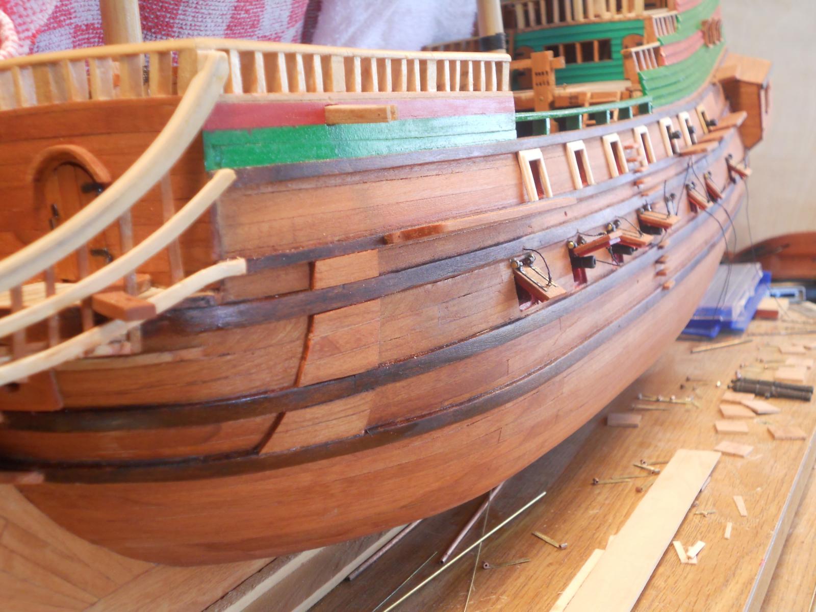
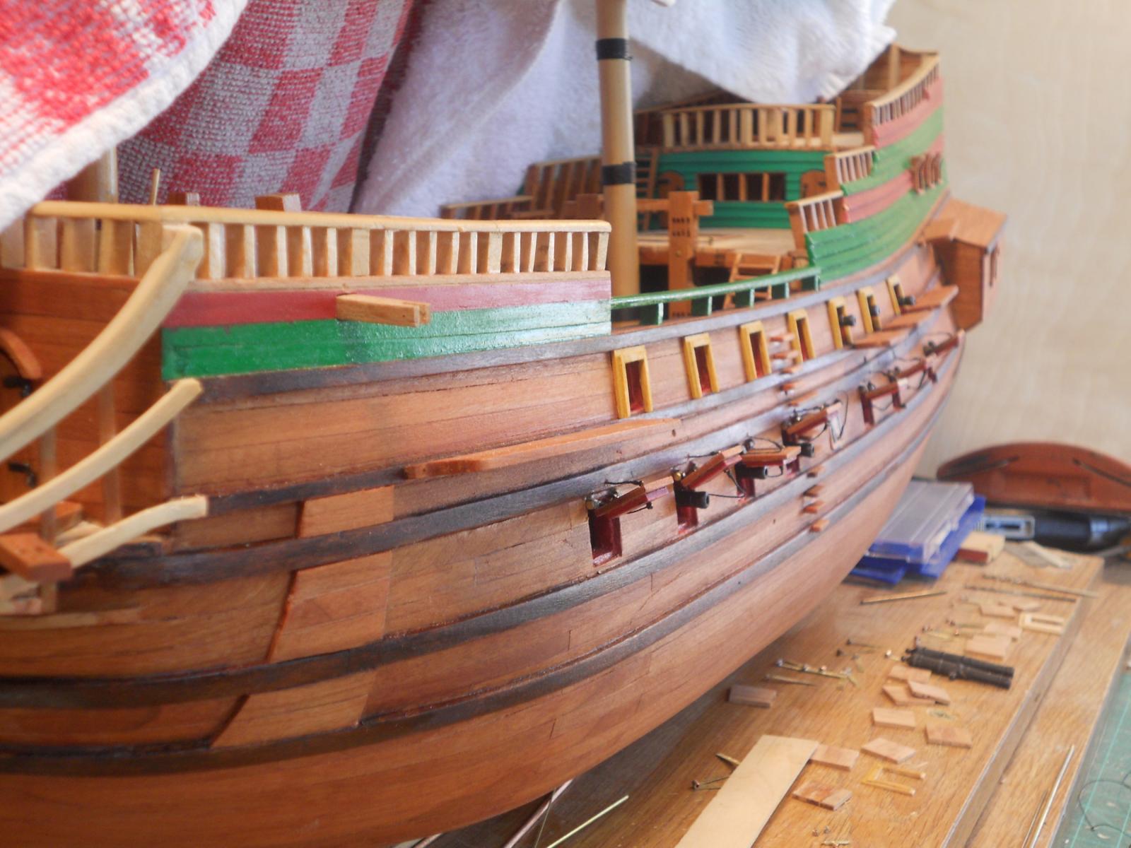
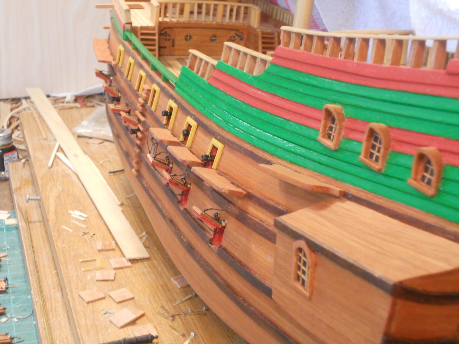
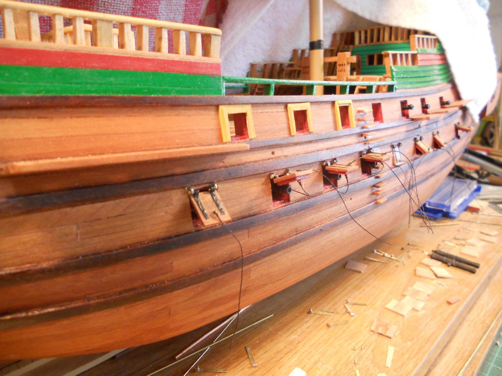
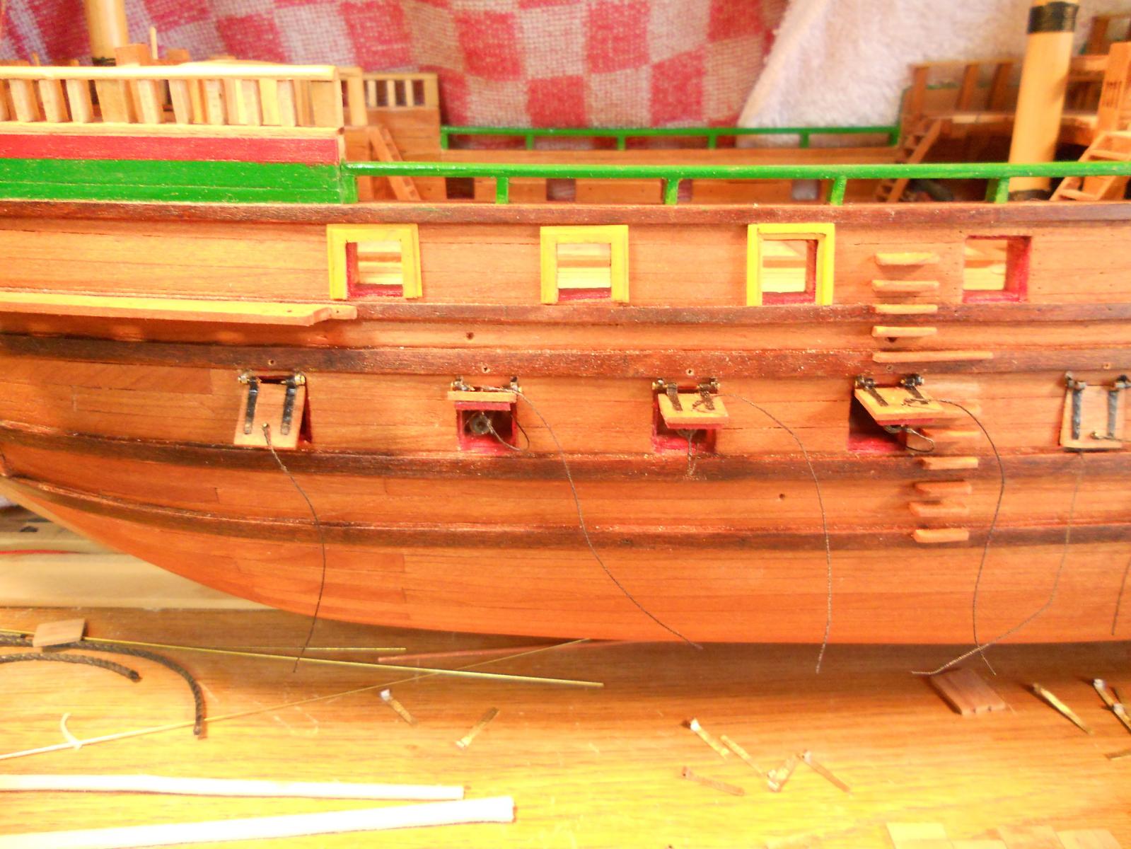
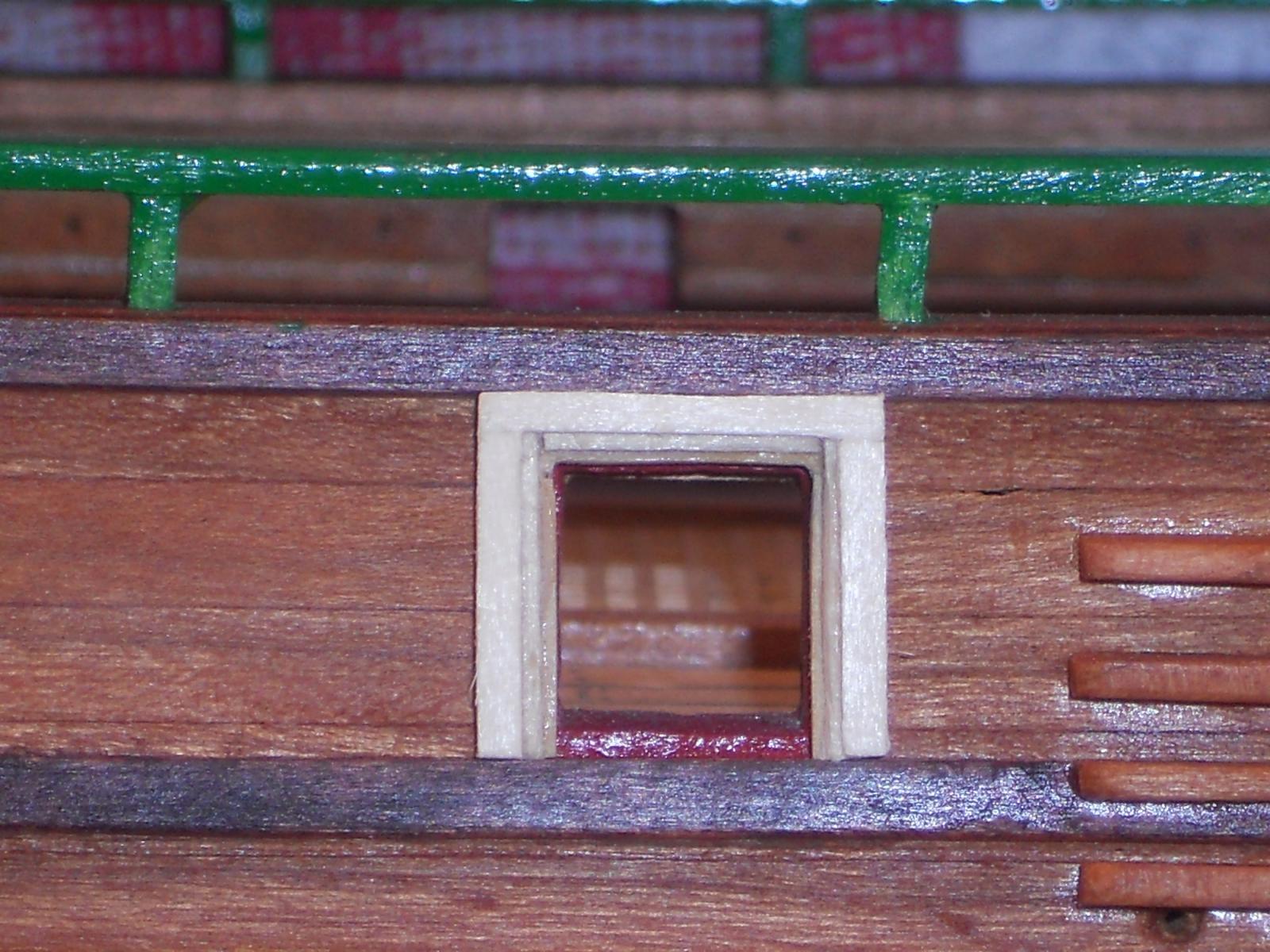
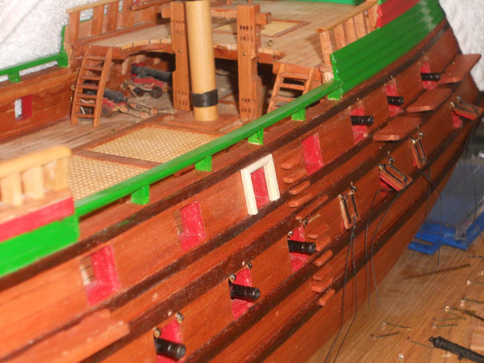
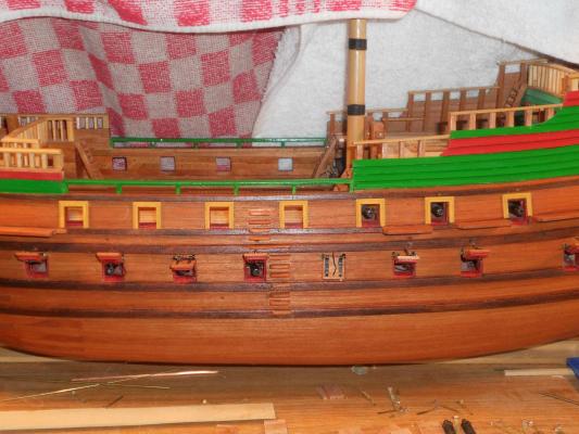
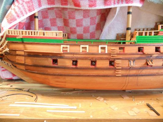
G'day to all y'all, I completed all seven top deck gun port frames, painted them and glued them to the fuselage, uhm, I mean hull I had to stiffen the gun port lid ropes so that I can push them through the guide holes. They'll have to remain loose for now till I have made and installed the shroud deadeye chains. Not much room to work around them. I am leaving one gun port closed. The first two pics are of the unpainted frames just loosely stuck to the hull. The rest are the painted frames glued to the hull with a few drops of CA glue. Head on view of the completed and unpainted frames, port side. View from the port bow of the completed, unpainted frames. Head on view of the port side painted frames. View from the port bow of the completed and painted gun port frames Stern view of port side painted frames. Cheers


-
@ Mark: ah yes, we should all listen more to our admirals, difficult to do for a stubborn Dutchman @ Jan: Thank you Jan and I have relayed your compliments to the admiral. She said that you must be a very wise individual I have made seven new frames and these are really looking very nice, even if I say so myself, the carpenter. Perhaps I can paint and glue them to the hull tomorrow. I'm also trying to complete the lower gun deck port lids. They are already mounted but need to be secured yet. Pictures are forthcoming and please let me know what you think. Cheers
-
Thanks Gino for adding your clarification. Not much is known about these old boats anymore or so it seems, including the crews. I'm counting on you my friend to add your knowledge about this particular sub. I understand you know about the K XVIII that visited the USA when it traveled West to NOI (Dutch East Indies) before WW II. But for general info I like to add this for the benefit of the members. I also want to add that my father served on that boat as well for a short time when it was in Indonesia till 1938, when his tour of tropical duty was up in 1938. He and his family had to return to the Netherlands and It was then that he was placed on the O 19 and sailed with her back to NOI in 1939 with his family following. @ John Texxn5: Yes, very much so, even though that I have spend my entire life in aviation. As my introduction to this log shows, its all because of my father. Interesting bit of info about that Jap sub with 2 metric tons of gold. Good luck with the salvage operation! I and thousands of others would like to get some of it as restitution of everything we lost during the Japanese (and I'm being politically correct here) occupation of the Dutch East Indies. I, my mother and sister were interned by them for the duration of the war. In 1943 the Japanese classified us all as combatants and became POWs. The Japanese have given us half the peace sign to our claims for restitution, primarily thanks to Douglas McArthur. Well, it's a long story and maybe someday I can write about it and publish my story. @ Sjors: You can actually read that Dutch language stuff? You must be a Dutchman then I can actually read it too and I'm an American, brahaaaahaaa - - - and I have forgotten most of my German, French and Indonesian languages. Cheers all y'all
-
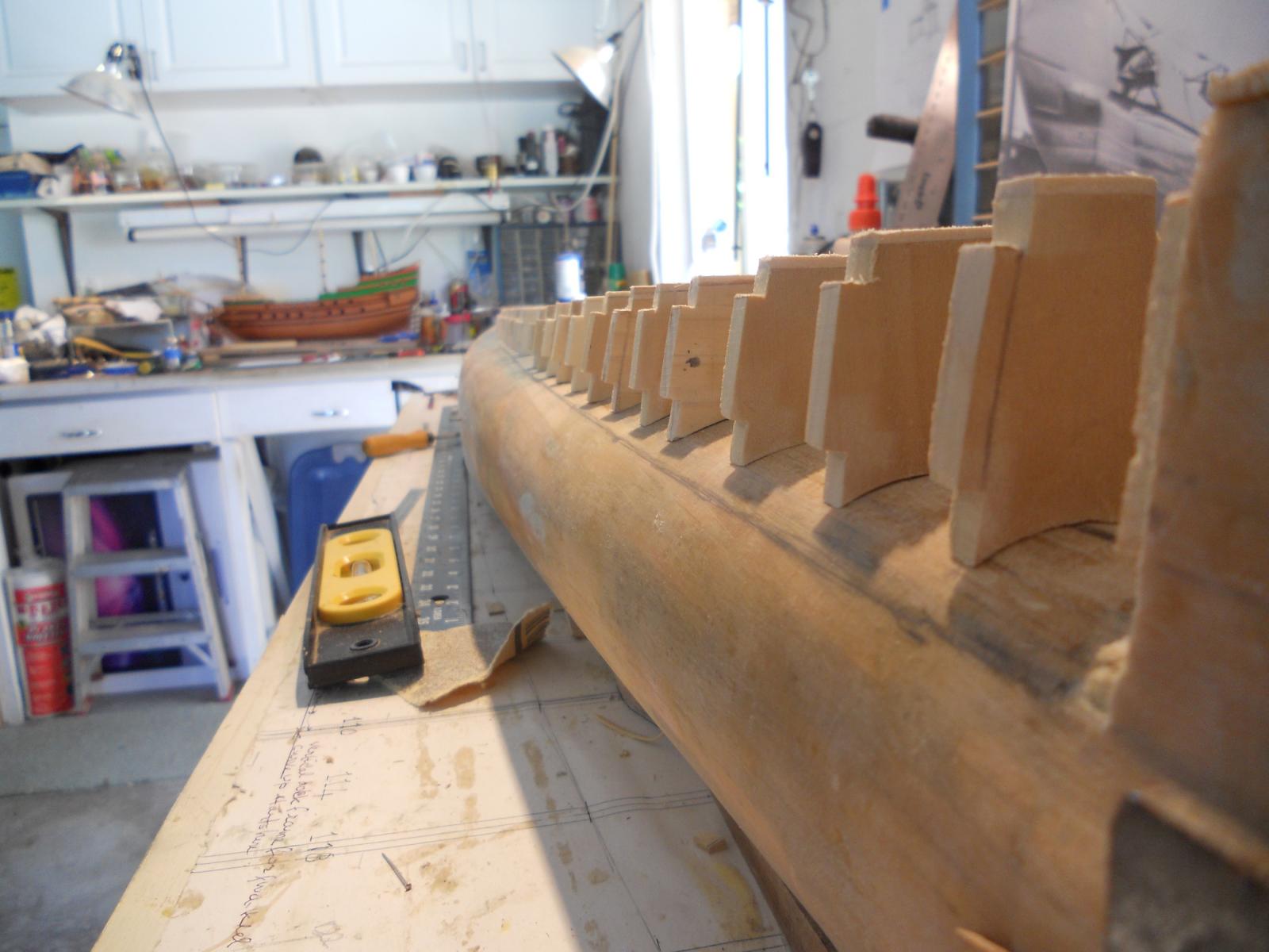
After my dentist visit of this morning I proceeded with my gun port frame project. We finally got around to fix the disintegrating bridge anchor. He had to use a slide hammer to get the bridge off. After many hammer blows it finally came off, my poor brain is still shaking. After some surgery and removal of the disintegrating tooth root he temporarily replaced the bridge so i can eat. Next Thursday back again for the same treatment, more hammering and grafting some bone material into the jaw. Sewing things back up and putting the bridge back permanently I got some yellow ocher oil paint out of my artist paint supplies and painted them to see how they look and just placed them over the ports. I then asked the Admiral which form she likes best. She preferred the ones like shown on the Padmos. So, we'll make the frames with the steps facing to the outside. After I made the pics shown below I completed four new frames but have not painted or installed them. I made them a little skinnier and they look very nice. I also fitted the lower gun port doors on. I still need to secure the hinge pins and the pull ropes. We are progressing This is a head-on shot of the experimental frames. The admiral (Gwen) likes the two on the left. The yellow ocher looks very yellow in these pics but they are truly yellow ocher. Here you can see the steps in the frame clearly. They will be made a little narrower. Even with the cloths draped over the ship dust still gets on the ship. This pic is taken from the bow to show the steps in the frames more clearly. Cheers


-
Thank you all for the likes fellows, appreciate it very much. @ Gino: Thanks for jumping in Gino, yes, I remember now that you mentioned that about the deck tubes possibly being deactivated but they may have left the doors off. Also, now that you mentioned it about the crew Christmas pic and the table. Need to dig that pic up and look at it again. @ Kevin: Most likely an optical illusion. From this angle and distance the stern part is foreshortened and that tends to make that area "fat" looking. My model's hull is made from the official drawings out of the Navy Archive in Den Haag, so I assume it is correct. Another reason may be that the boat in the picture is shown in the water, hiding a lot of hull. @ Freek: Yes, I have also noticed the same thing. Could have been someone who didn't know. Well, the O 19 and O 20 have only two rear tubes. Yes, the O 19 and O 20 were designed with the deck tubes. The interior picture of 1939 in my previous post shows the rotating and aiming mechanism. Also the drawings show these tubes as part of the original design. I have seen photos of earlier Dutch subs with deck tubes, thus it was something typical for the KM to outfit their subs with the so called deck tubes and dates back to the early 1930's. Congratulations on getting your tubes to fire What did you use for power? Compressed air? Springs? Rubber bands? Cheers
-
Thank you all for the likes, appreciate it very much. Mark, yeah, tough shot on this. I do like the idea of a frame around the gun ports and preferably in three layers but unfortunately the wales are just a little too thin. But in this scale probably just about right. I think the 2 layer approach is gonna work and a little narrower. The yellow ocher will really offset it nicely and compliment the cherry hull. Today was spend in mowing the front yard before the rain showers hit and then I spend a few hours at my colored pencil society chapter meeting drawing a picture of some small lilies. The ship and boat yard was closed for today. I also had to do some research for our daughter and give her some advice in finishing miniature furniture. She is taking up this hobby again. Oh, this brought back some fine memories where I kinda helped her with assembling and finishing miniature furniture when she was 12 years old. I was not telling her how to do it but just asking questions how she was going to do it. We were going to build a doll house in a 5 gallon water bottle! Time well spend overall. Cheers
-
Thank you all for your likes and suggestions. @ Lawrence: to me, to make a model of the Victory must be one of the most ambitious projects anyone can undertake, regardless if it's kit build or scratch from plans. If I would ever attempt to do that I'd definitely need another lifetime I'll be happy to complete all my current and planned projects before Davy Jones calls @ Mark: hmmmm beveled eh? I didn't think about that possibility. A thought and see how it looks like now that I'm experimenting anyway. Yes, I intend to paint these frames in yellow ocher as Jan suggests. I have removed the outer layer of the first attempt but didn't paint it yet. Then I made two other frames with the layered steps as done on the Padmos model. I also made the layers thinner to make them come out even with the wale above it. The picture below doesn't show the steps too well and I will have to increase the thickness just a tad to show the steps in the frame and also somewhat narrower. When visually looking at them the steps are clearly visible though. I'll have to do some more experimenting to arrive at a satisfactory looking frame. With a scale of 1:80 things do get kinda small. The most right one, just to the left of the steps, is the original with the last layer removed and the step inside. My thinking on having the steps inside is to enlarge the gun aiming window of sight. However, I guess that the left / right sighting was not really that important, it was rather the up / down sighting. The two on its left are the two layered frames with the steps on the outside. Either way they look all right to me but could be somewhat narrower with the steps more pronounced. Okay, a little more experimental work and let the Admiral make a call She does have an eye for things like that. Cheers
-
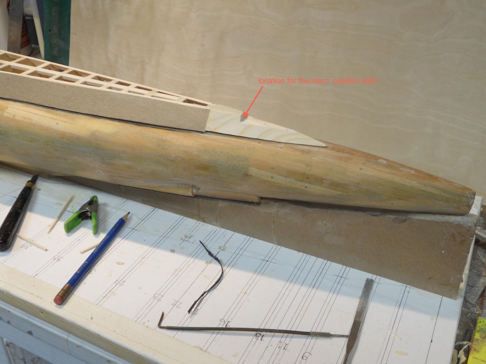
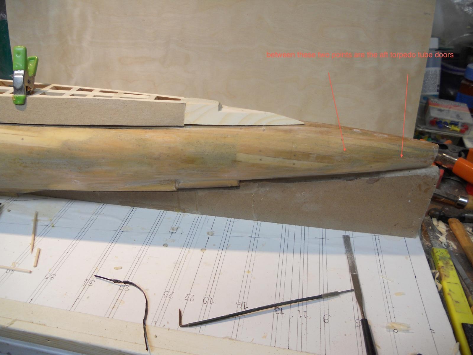
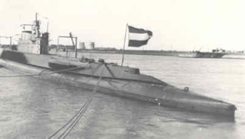
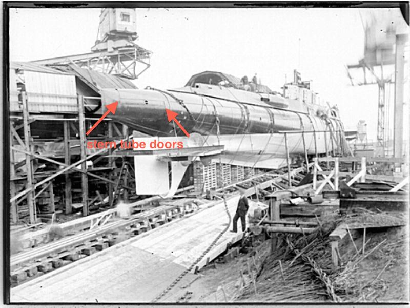
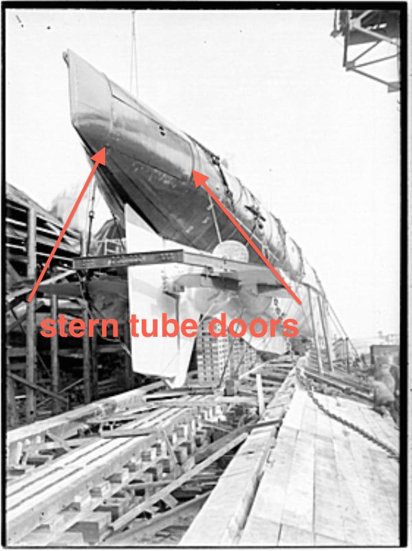
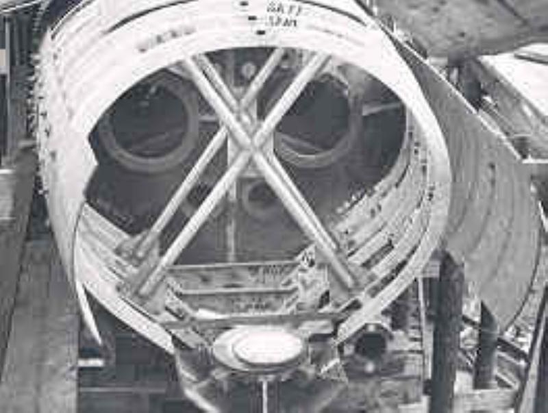
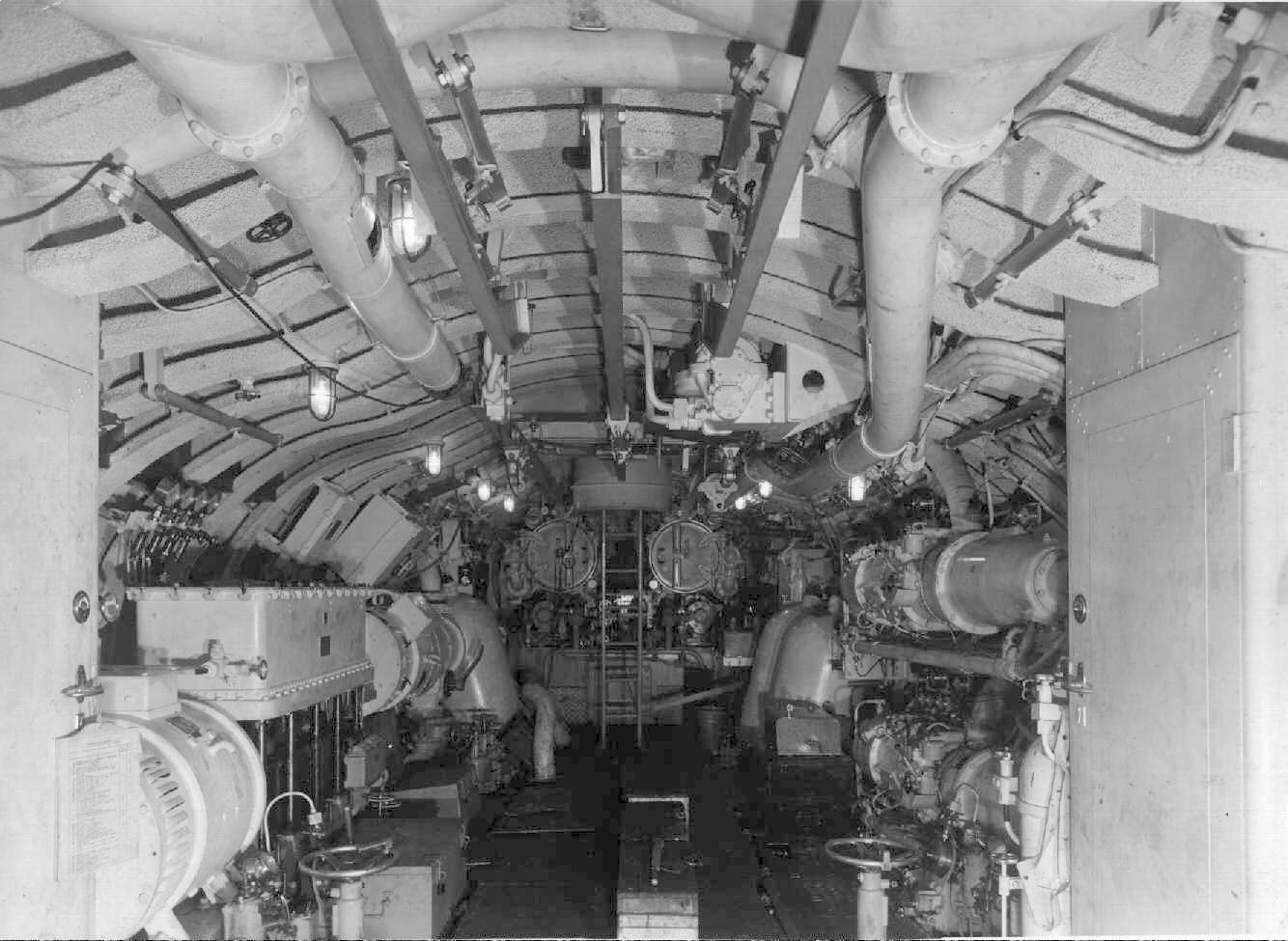
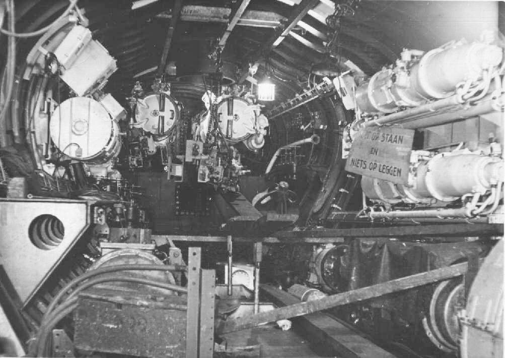
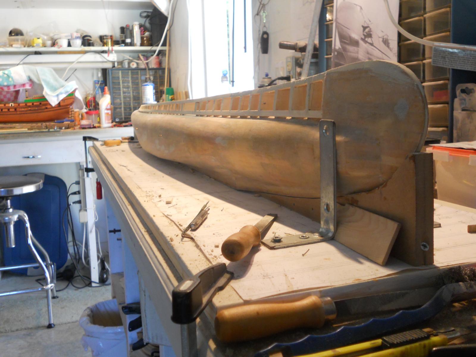
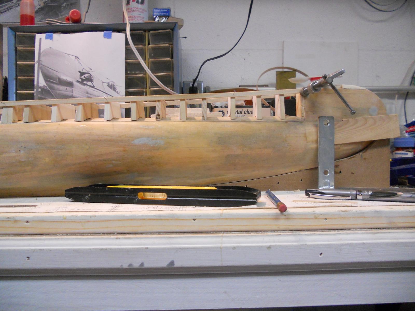
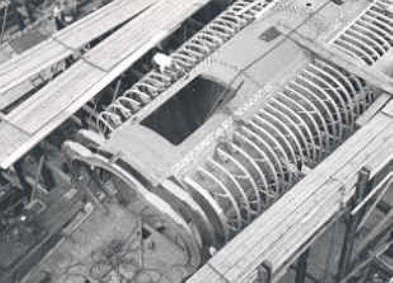
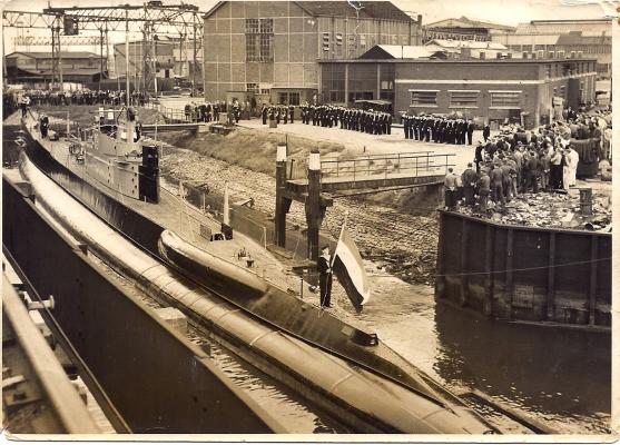
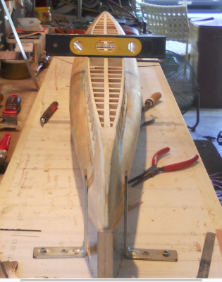
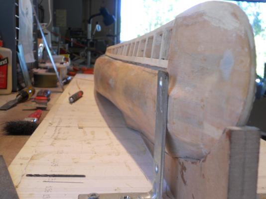
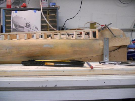
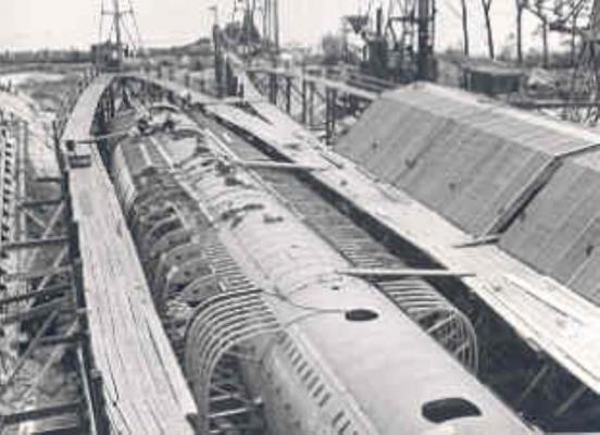
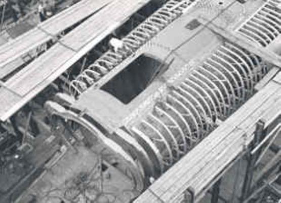
Thanks for your "likes" folks and Ian, yeah, cramped indeed but this was the largest, most modern and most comfortable sub going. Then to think that I was actually in this boat sometime at the end of 1941 at an open-house visit. Okay, I took a few pics of the stern deck fairing this afternoon. I'll also indicate where the stern tube doors are located and compare my build with photos of the original build of this sub. I hope you like the photos of the original build. It does bring back memories side view if the stern fairing, annotated where the stern position light will be. side view of the stern with annotation where the stern torpedo tube doors are. Stern view with the aft deck fairing installed. This picture was most likely taken in 1943 when the O 19 was overhauled and refurbished in Scotland. I shows the aft deck fairing best. This picture was taken at the commissioning of the O 19 in 1939. It also shows the aft deck fairing and all the other "stuff" that needs to be installed yet. The bulged areas on the sides are for the diesel engine exhausts. This picture was most likely taken when docked at the Naval Base in Den Helder in 1939 just prior to sailing to the Netherlands East Indies with my father on board. This was just prior to the launch in 1939. I indicated where the stern torpedo tube doors are located. another view of the O 19 on the stocks just prior to launch in 1939. Here too I indicated where the stern torpedo tube doors are located. Stern tube compartment during early stage of build This is the stern tube compartment of the O 19 at the final stages of the build. My father would have been present at that time of the build of the O 19. Stern tube compartment during intermediate stage of build. This shows the framing of the stern torpedo tube compartment. Cheers


-
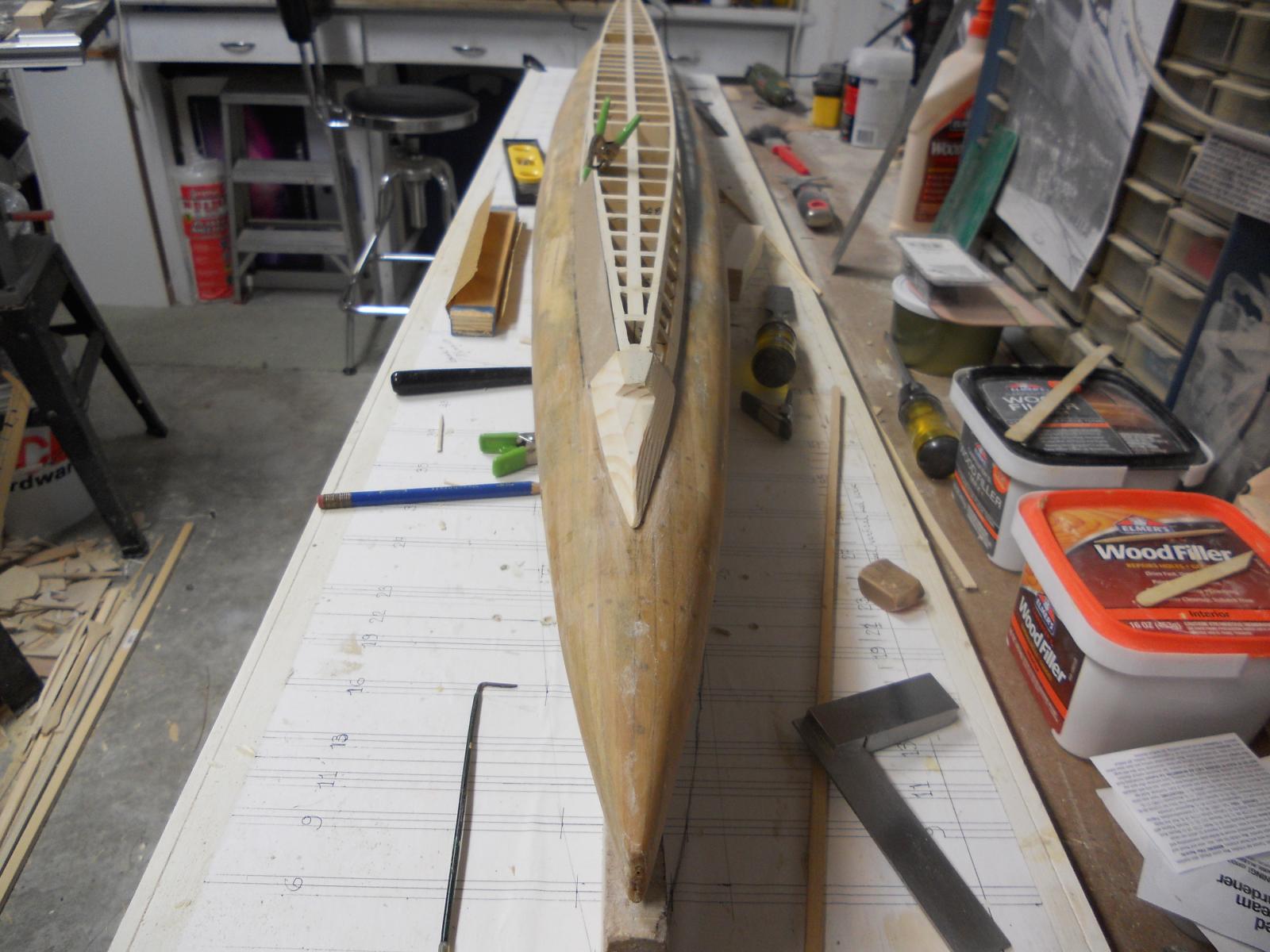
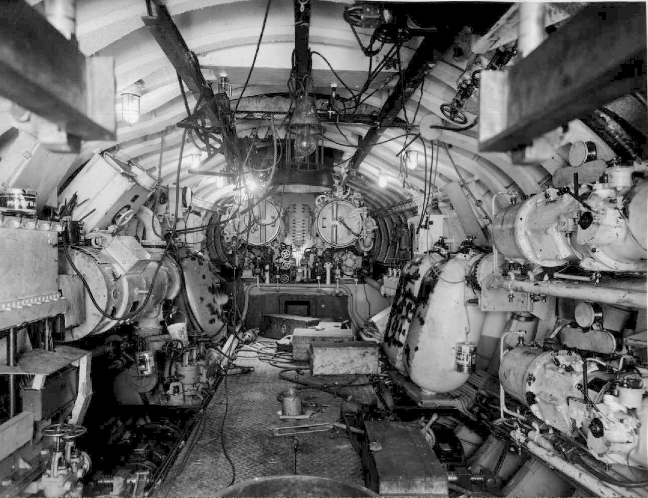
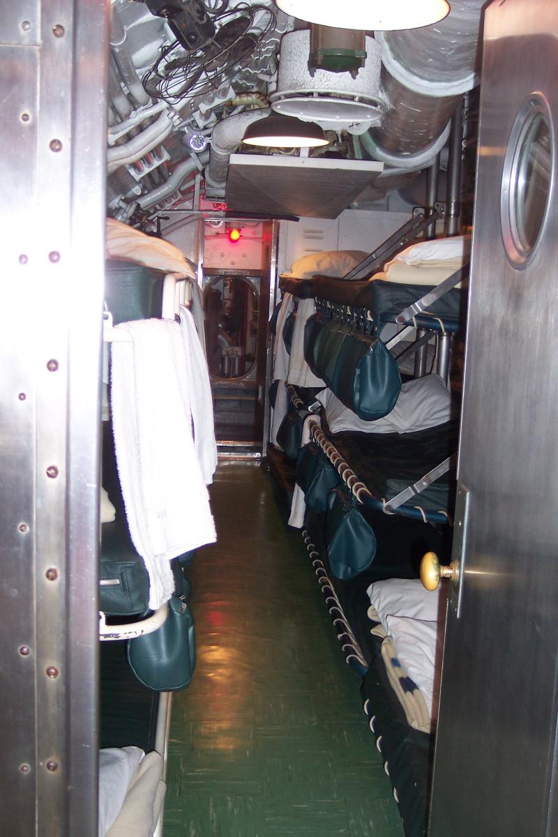
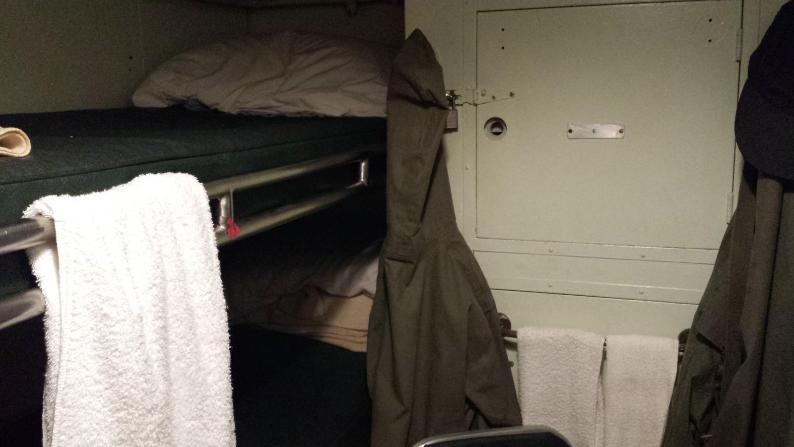
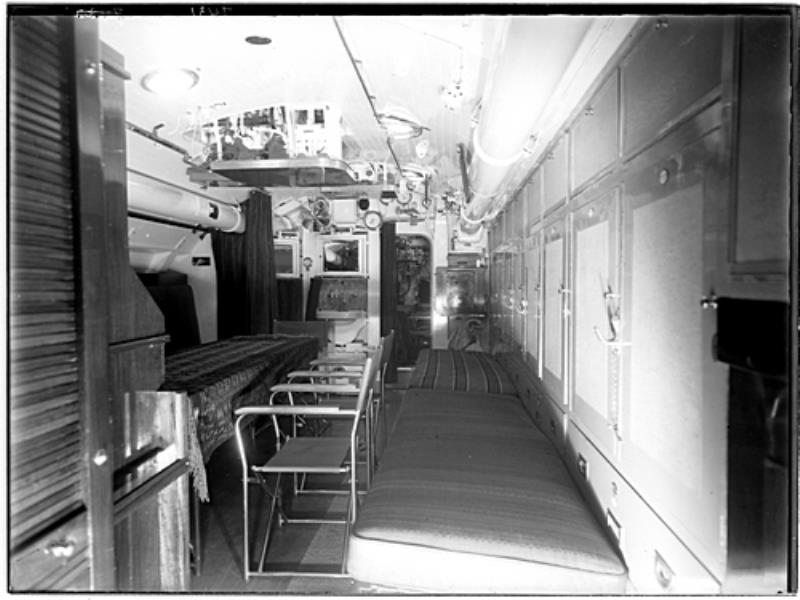
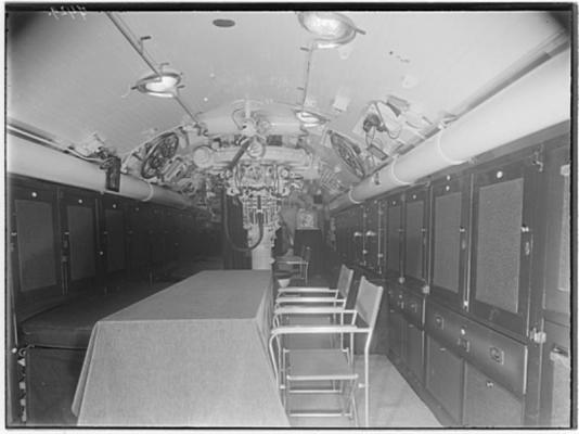
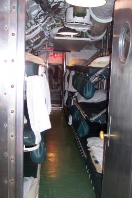
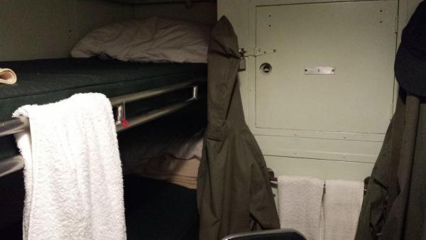
Thanks everyone for your likes and Wacko Joe, thanks for dropping in, yes, she is coming along fine. Today I tweaked the few small areas and carved to aft part of the deck fairing out of a piece of solid pine. May take a pic tomorrow after my dental visit and lunch. Am ready to put the side panels on In the meantime here are a few shots to compare sleeping accommodations between the O 19 and the Gato class sub USS Cod. This is the Non Com Officer's quarters on board the O 19 at the time of her build. For locating the area go back to the first pages of this log. Most bunks are stowed. I am assuming that the table and chairs are for the publicity photo, I can't imagine having them taking up so much room. But on the other hand it is possible that the top of the table can fold down. Perhaps Gino den Ridder can shed some light on it. That contraption you see hanging from the ceiling should be the deck-launch torpedo aiming device. That was quite an elaborate contraption and difficult to use. That whole affair was removed from the O 19 when it was in overhaul and refit in 1944 in Scotland. In any case, this would be the compartment where my father had his bunk. This is a photo I took when visiting the USS Cod in Cleveland last month. It appears to be the regular crew accommodations. This is also a pic I took on the USS Cod and it appears to be the officer's accommodations. The officer's quarters on the O19 were pretty good compared with the older boats but not as nice as on the USS Cod. Cheers,

-
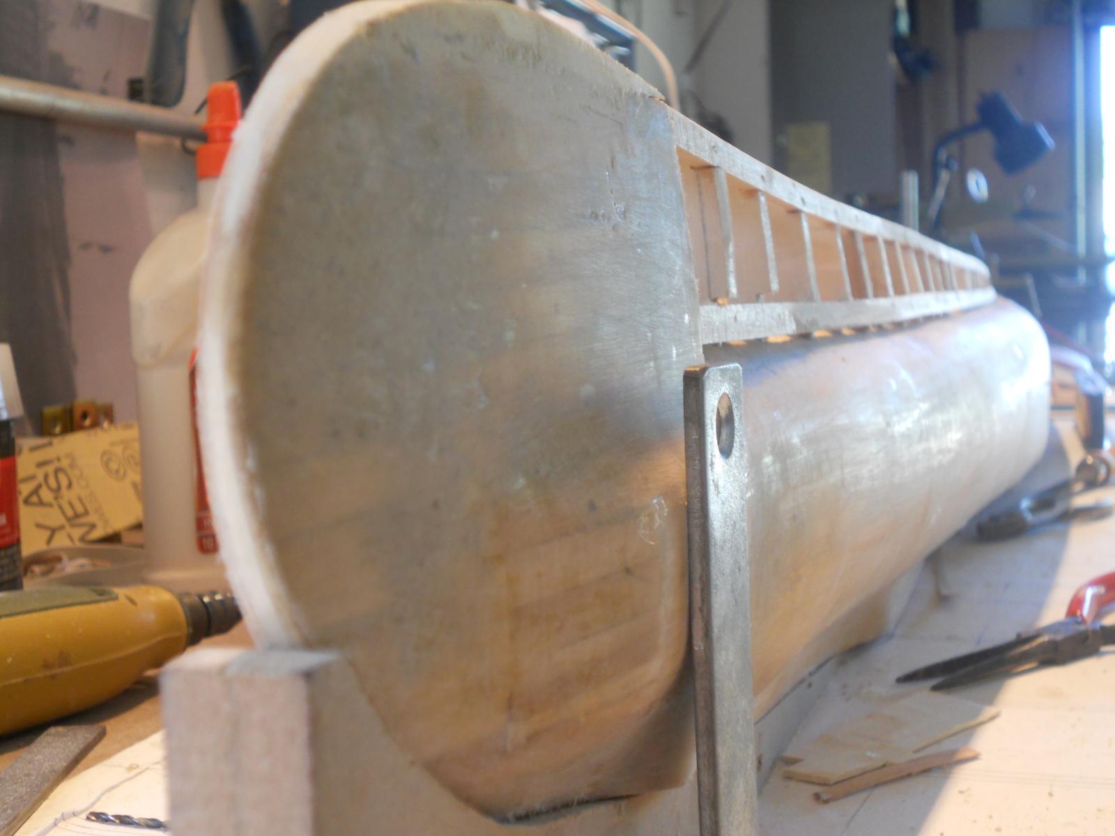
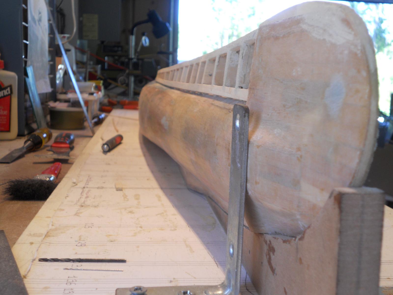
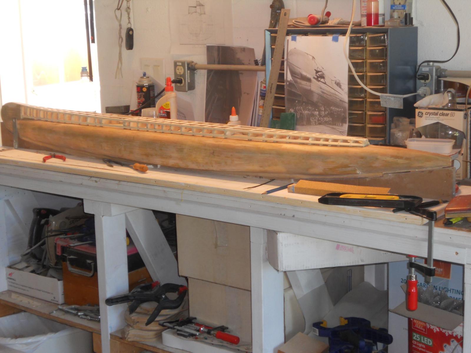
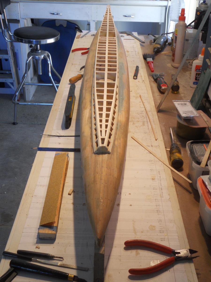
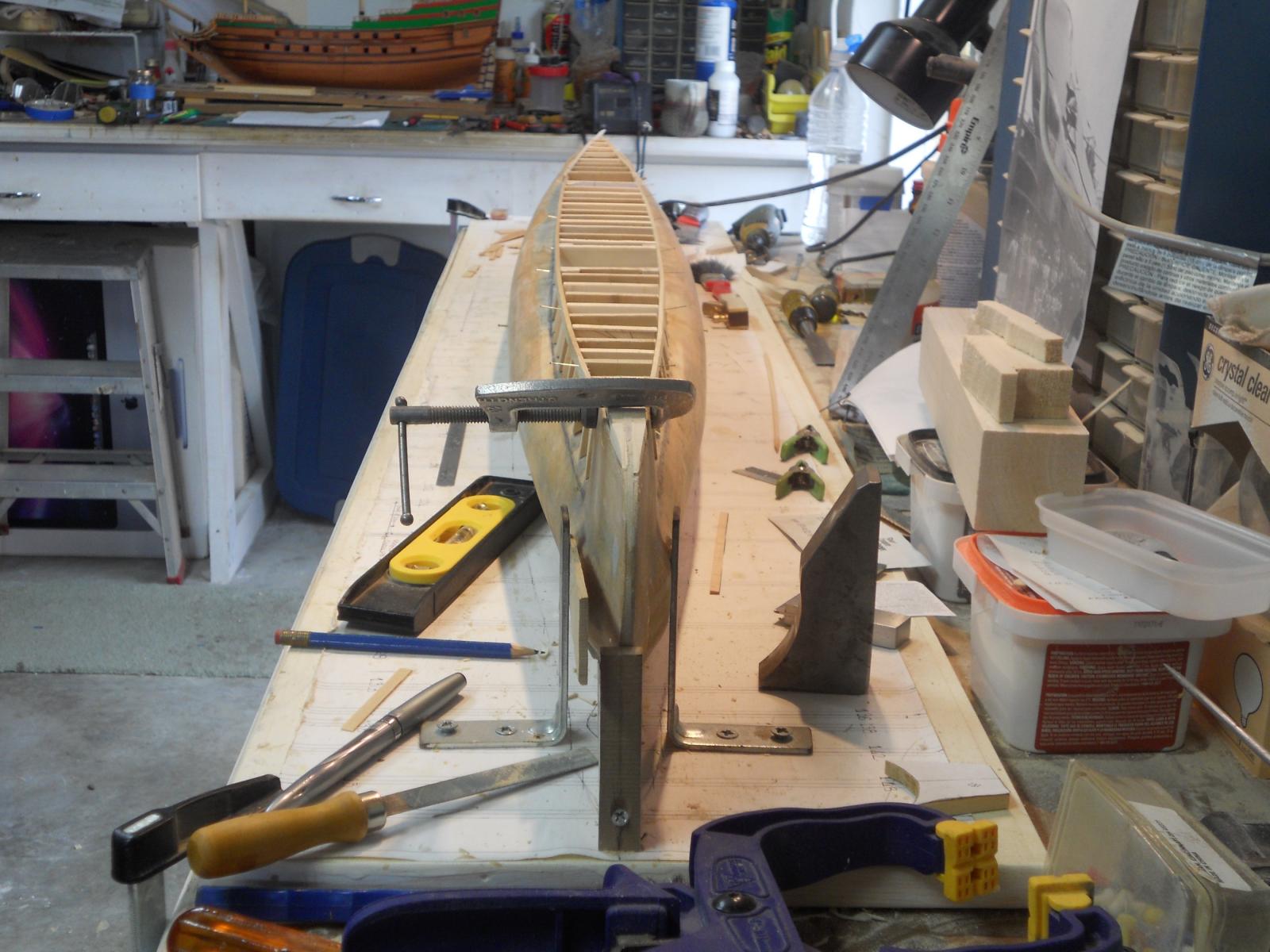
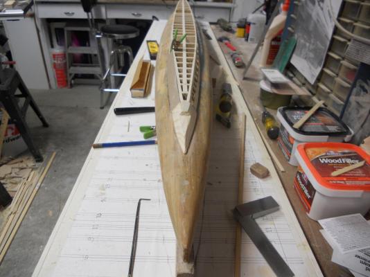
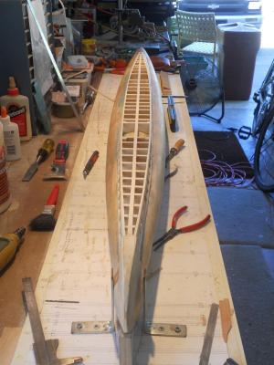
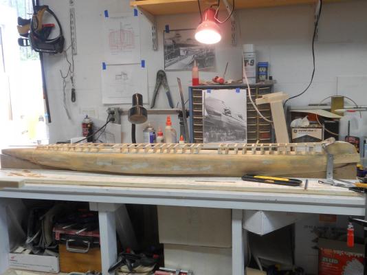
Hello all and thank you Popeye, Kevin and Sjors for stopping by the boat yard, really appreciate it. I have completed the roughing in of the deck structure. The photos revealed a few ares that need some minor trimming but overall I'm satisfied. We are talking of fractions of m m's but it's important for the side panels to lay nice and flat and even. It seems that my VOC ship is taking a backseat but I'll get back to it shortly. I took a bunch of pics from different angels, primarily to see where I need to do some shaving with sandpaper. I made a 10 inch sanding block that seems to work really nice. Final check for level of all the stations of the deck frame. I have put 4 brass nails in the side of the hull at water line 7, two on each side. This allows me to check the hull for level and consequently also all the structures and components for level. Kinda like a bird's eye view of the completed deck structure. I already suspected a few areas that needed some trimming and the photos confirmed it. I'll note them and sand them down a little. A shot along the port side from the bow. The dark area on the center of the top stringer seems a little high but that's an optical delusion A shot along the starboard side from the bow. Same optical illusion is seen here. A bird's eye view of the completed deck structure from the bow. A profile shot of the port side. Cheers,


-
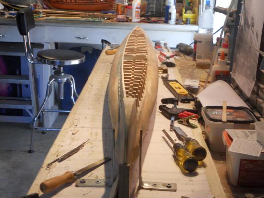
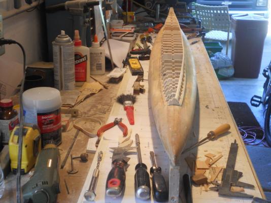
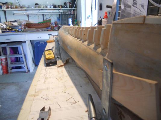
Thank you all for your kind words and likes, it really means a lot to me! All the deck frames are now solidly pinned and glued to the hull Today I proceeded to install the port side stringers. They are cut from 1/4 inch poplar to 3.5 X 6 mm. I used 1 mm wire brads as a clamping method and set the brads with a steel punch so I won't ware out my sandpaper Frugal Dutch No, not really because I need to have the sanding block make contact with wood to get a true shape. The brads prevent that from happening. So far it looks good but there are a few spots I need to shim a little. As mentioned before, the purpose of these stringers is to give the 1 mm plywood side and deck panels a continues glueing surface. The gap of the lower stringer is larger then necessary and of no concern because the 1 mm side panels are the ones that need a smaller gap between the it and the hull. I'm now ready to turn the build board around so I can work on the starboard side. I may or may not put the side panels on. I need to go back to the stern section and make and install the diving planes, rudder and propeller shafts. After that's done then I won't have to worry about damaging them later and can do almost everything else without lifting the boat out of the jig again, except for the finishing plating and painting. Okay, here are a few pics of what was done today. Pictures, yes pictures! We know there is another Dutchman who likes to see pictures Head-on bow view. Head-on stern view. Bow side view. Cheers,

-
Hello every one, Andriaan, I'm baaaaack This afternoon I made one of the gunport frames. I don't know, it looks kinda bulky to me. I made it out of three pieces glued together with CA. The wood strips are very thing but even with them at about .75 mm each it still adds up to a rather thick hole. Perhaps if I make them with the steps reversed like shown on the Padmos model it mat appear less bulky. The pictures below don't show what I see close up. Ill make one like the Padmos model and see how that one looks. Part of the apparent problem may be that my wales are rather thin making the outer layer of the molding fall outside the wale. I'll make one with the steps reversed like the ones shown on the Padmos model and perhaps one with only two layers. As a note of interest, looking at several of van de Velde's drawings the upper gundeck portholes have all lids. This doesn't mean I'll be going back to lids on the upper deck but it's just an observation. This shows the frame head-on. It's perhaps not noticeable to see what I see even with a side view, see next pic. This show the frame from the side and even here it's hardly noticeable what I'm talking about. They could also be made a little narrower. I think I begin to like the idea of some color on the sides of this ship. It'll also match with the future railing ends that I still need to make and install, also painted in yellow ocher/fake gold Cheers,

-
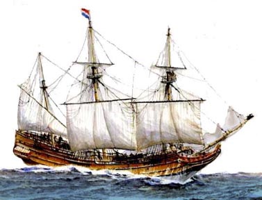
Hello Een-dragt, We are kinda highjacking Gyula's log and I hope he doesn't mind. Some added info on the name of his ship. Ah, Amsterdam, my favorite town to visit when I lived in the Netherlands for a few years after WW II. Both my parents were born and raised here. We would visit aunts, uncles and of course our grandparents. Jan is absolutely correct and a little research on your part would have come up with that and a lot more. Concerning one of the ships called Eendracht William van de Velde has a nice sketch of a 1663 ship. There is also a nice painting of an Eendracht. One of these days I want to do an oil or watercolor painting of my own model. Cheers,
-
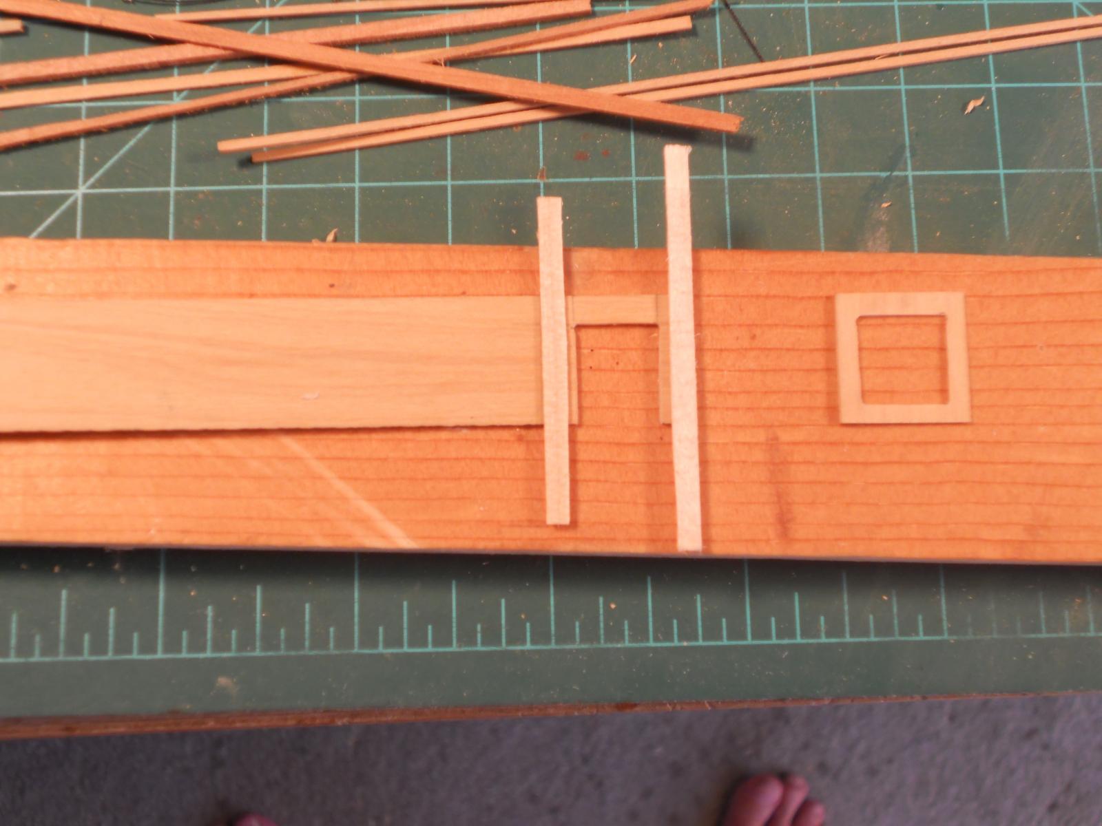
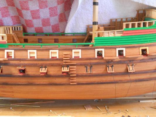
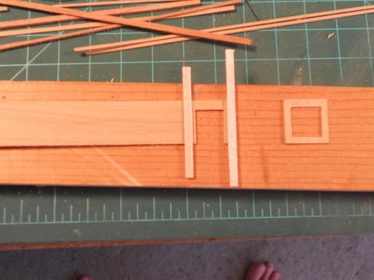
Hoi amateur Jan, yeah, I was kidding with the fake gold for the gunport moulding. My fake gold paint is yellow ochre, but one can always dream I know, I know, the frugal VOC or maybe just practical. No expensive stuff on a working ship. I did buy some "gold" paint at the hobby shop and see how it looks compared to yellow ochre. I have been busy with my O 19 model but took some time this p m to make a start at the upper gunport "scroll work." On my model the bottom of the gun ports are at one of the wales so they'll look like the ones on Patmos but in reverse I like to make the step looking frames also in reverse as shown on the Patmos model, like one would make a mat for a picture or a frame for a painting. Just to be different. & Lawrence: Thank you for the compliments The thing I'm missing is more knowledge about these old ships. Have been doing a lot of reading and looking at paintings and drawings of them but still come up short. That's why it's great to have folks here who know a lot about them and can help, even when not asked. Amateur Jan has been invaluable with his advice and direction. As far as skill? My training is all technical, first as ship machinist with certificates in about 13 different trades. Then switched over to aircraft design technology and repair. Consequently I'm quite familiar with all kinds of tools and can visualize structures as they should be. I'm also not unfamiliar with working with wood. Ships in bottles, model railroad stuff, marquetry, remodeling houses and etc. As far as scratch building is concerned, not much different then kits. You just have to make your own parts and can use drawings and guidance manuals that are available. Now that you know how your kit parts have been made it's not that difficult to make them yourself from drawings. You will need some (power) tools though, at least that is nice to have. All I have that's useful is a bandsaw, a sanding disc/belt and a Proxxon jigsaw. My DB 200 Unimat is helpful but I can do with an electric drill The rest are hand tools. A lot on the VOC ship is done with just the hand tools and yes, it takes a little longer but so what, I'm retired and have the time. After your Vic is finished you should take the plunge and start a simple project, POB ship. You seem to be doing alright with your Vic, so why not. It certainly is a very rewarding experience and there is plenty of advice here on MSW. Go for it! Okay, below is one picture of my gunport frame project. It's just in the beginning stage so it still looks very crude. I sanded down a plank of boxwood to 1 mm thick and drew the outline on it and the 10 mm inside opening of the gunport. The thin strips of cherry wood are to be reduced in size to fill the gunport rabbets under the moulding. They'll be about .5 mm. I'm not quite sure how wide I'll be making them, as narrow as possible but still wide enough for a nice looking frame or moulding. Stay tuned for the end result Cheers,
-
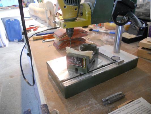
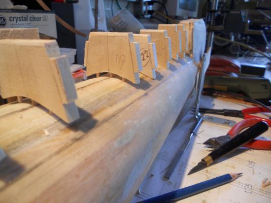
Hello everyone, Well, today is our Fourth of July celebration and after doing a little yard work I managed to do some more work on the O 19. I cut the corners out of all the deck frames to receive the reinforcing strips. This also allows a firm glue foundation for the side plates and the deck plates. After this was done I drilled two additional holes in each frame for bamboo pins to attach the deck frames more securely to the hull. I was able to complete just half a dozen and transferred the locations of the extra pins to the top of the hull and drilled the receiving holes. The pics below show the progress. Looking aft starboard side. Looking aft port side. Another view looking aft port side. Here I am drilling the extra two holes for pins to help secure the deck frames to the hull. Frame 117 is just entering all three holes in the hull for a show and tell. Cheers,


-
Move over everyone, make some room at the bar for this little old Dutch American. I need a beer, a tall, cold Belgian beer! Where is the barkeep now that we need one Nice looking boat Adriaan, really very nice! Cheers,
- 1,038 replies
-
- 1
-

-
- King of the Mississippi
- Artesania Latina
- (and 1 more)
-
Hoi Jan, Ah, pic is wonderful! Very clear and that's PLAIN ! I think I can do that, a lot of cutting and gluing but it'll look marvelous in fake gold paint That'll make the other gun ports jealous You must live close to the museum to take these shots just for little old me Thanks Jan, that's what I'll do, seems like a nice little project. Cheers,
-
Hoi Sjors, I'm holding the horses but they are getting restless, snorting and stomping their hoofs. Oh, sorry, that snorting was me, coming from the wrong end, hmmm, snif, snif - - - - Cheers my friend,
- 1,873 replies
-
- 2
-
-
- occre
- san ildefonso
- (and 1 more)
-
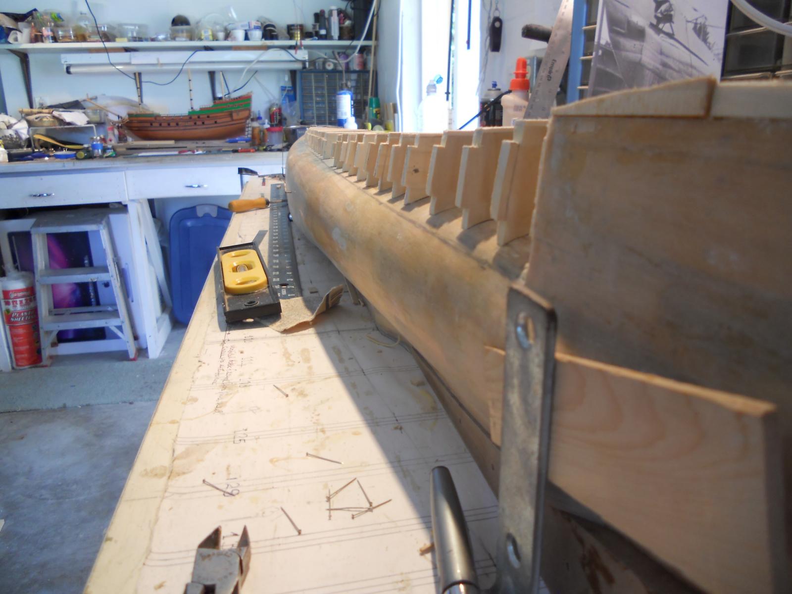
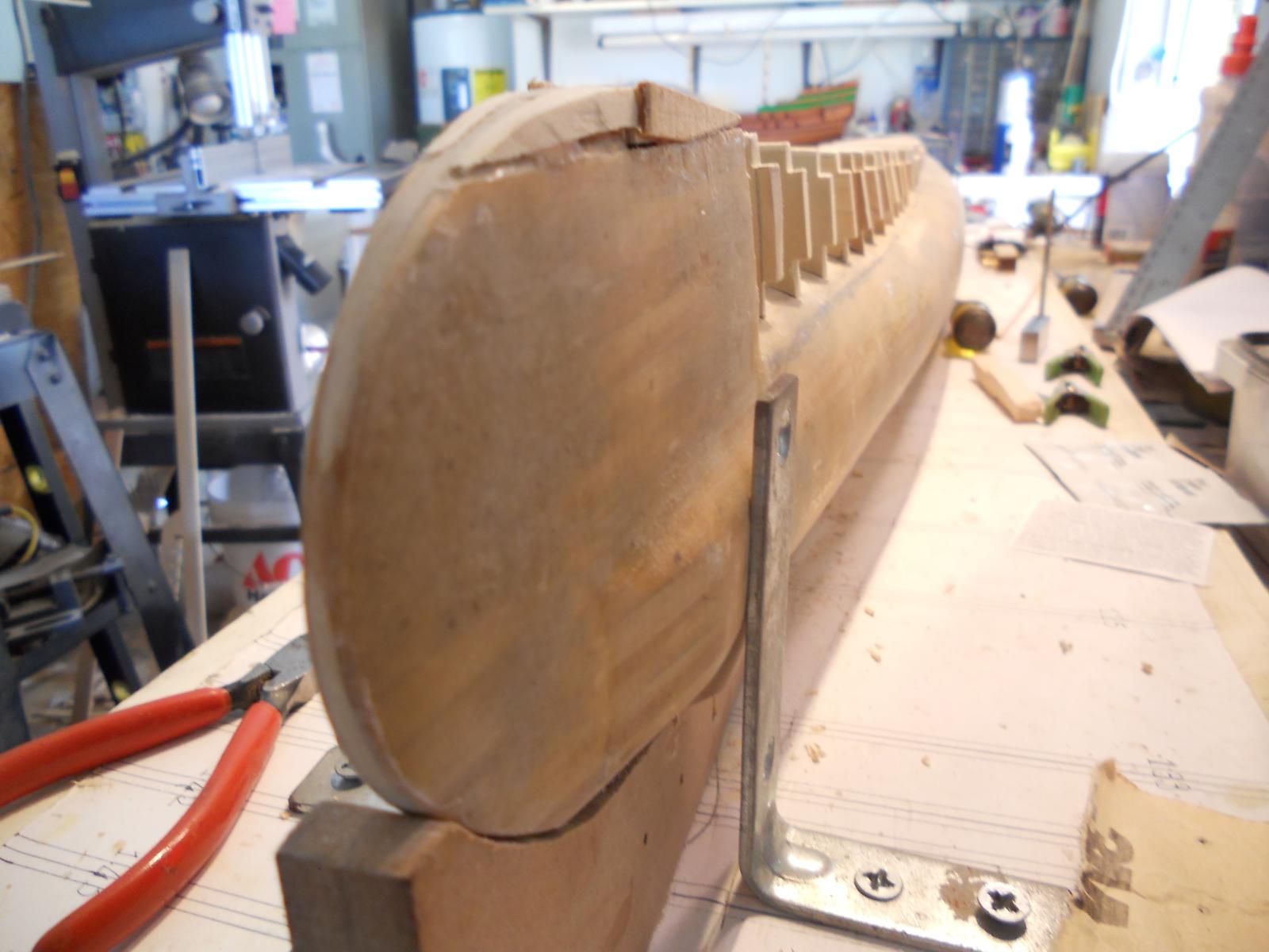
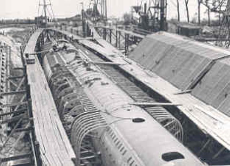
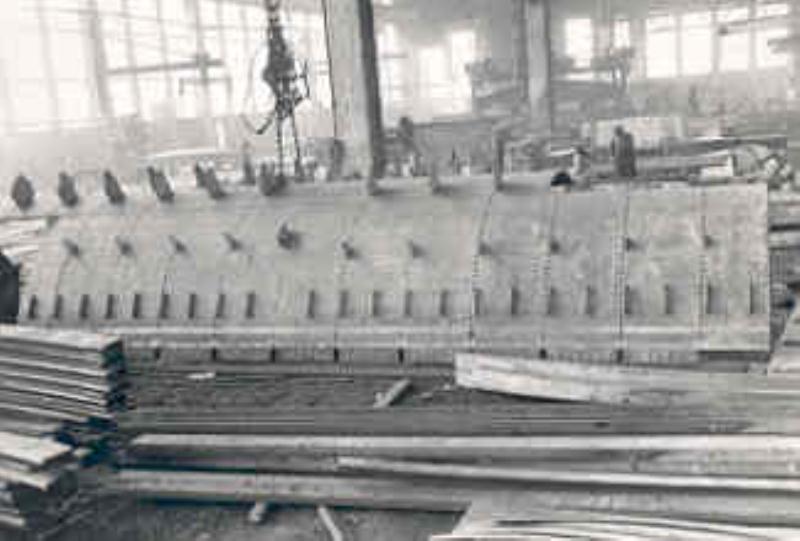
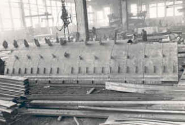
Thanks everyone for your kind comments and the "likes." @ Mark, This visit was quite emotional. Many memories flooded back into my mind. My father did give me a tour on the O 19 at the end of 1940. With the photographs I have obtained of the O 19 build and now actually touching a real sub made these memories come to life. My grandson? He wants to become a van Warmerdam and plans to apply for a name change. Well, I have resumed working on the deck frames. They are still just pinned with one pin and loose. I have now temporarily pinned a 1.5 X 6 mm slats to the top sides of the deck frames to check the alignment and form. There are only a few minor adjustments to be made but overall she's taking shape. When I am satisfied I'll cut the corners out of each frame on the top and bottom to glue 3 X 6 mm slats into these cutouts for support of the 1 mm plywood for the side plating and the deck plating. When the O 19 was originally build the deck frames were attached to the pressure hull with steel angle clips welded to the skin plates. There was a slitted opening between the hull and the deck structure to allow the water to drain away when surfacing. I don't have a clear picture from the original build but have attached a few that may give you an idea. Side view of hull with the check strip pinned to the upper part of the deck frames. Bow side view with the check strips pinned to the upper part of the deck frames. The typical Dutch upward curved bow can be seen taking shape. Head-on bow view with the check strips pinned to the the upper part of the deck frames. Hull with main ballast tank and mine tube compartments. The deck frame clips are difficult to make out but are just above where the ballast tank frames are joined to the pressure hull. This is a close-uo of one one of the pressure hull plates with ballast tank and deck frame clips attached. Another close-up view of the pressure hull and main ballast tank frames. The deck frame clips should be just above the ballast tank frame attach points. Cheers,

-
Hoi Jan, thanks for the advice. Here I envisioned dolphins, palm trees, roses, cupids and dancing girls No really, just something simple like a twisted rope kinda idea. I'll draw something up and post it for y'all to see and comment or anyone can submit some ideas Yes, she is just a plain Jane as far as ornamentation is concerned. Cheers,
-
Hoi Adriaan, Good to see that things are going back together again. She's looking really great and looking forward to see her all lit up. Cheers,
-
Hoi Sjors, Happy birthday and I trust you had a great day. Here's to your health and many more Is it still raining in your neck of the woods? Silly question, sorry, it's always raining. I lost my gills soon after I came to the States Is Narcis plein in Vlaardingen Ambacht still there? Or did it float away? Just thought I'd ask, haven't seen pictures yet of the house I used to live in way back in 1938 - 1939. btw, nice going with the ship. Rigging soon? Cheers,
-
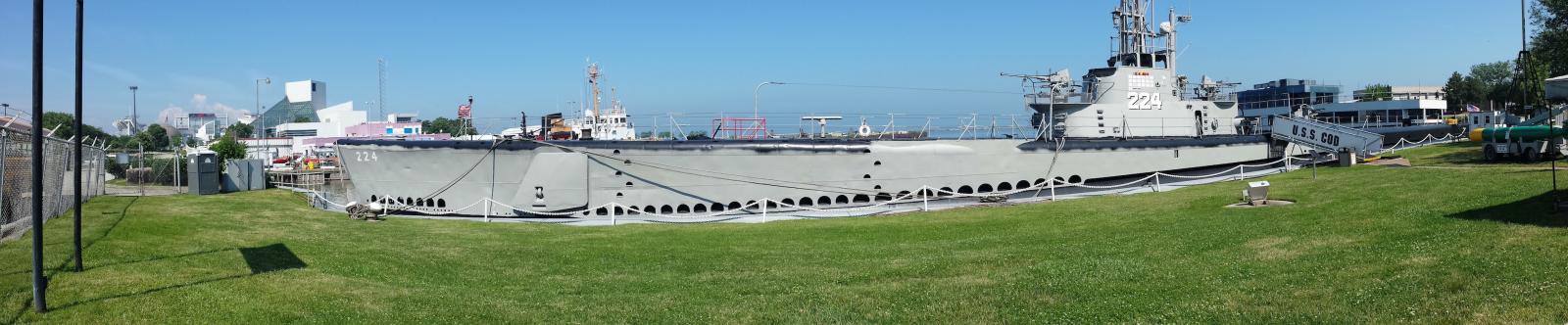
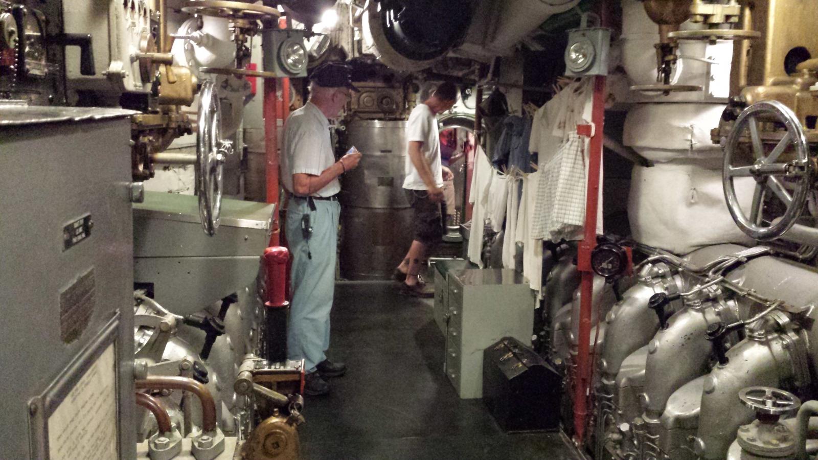
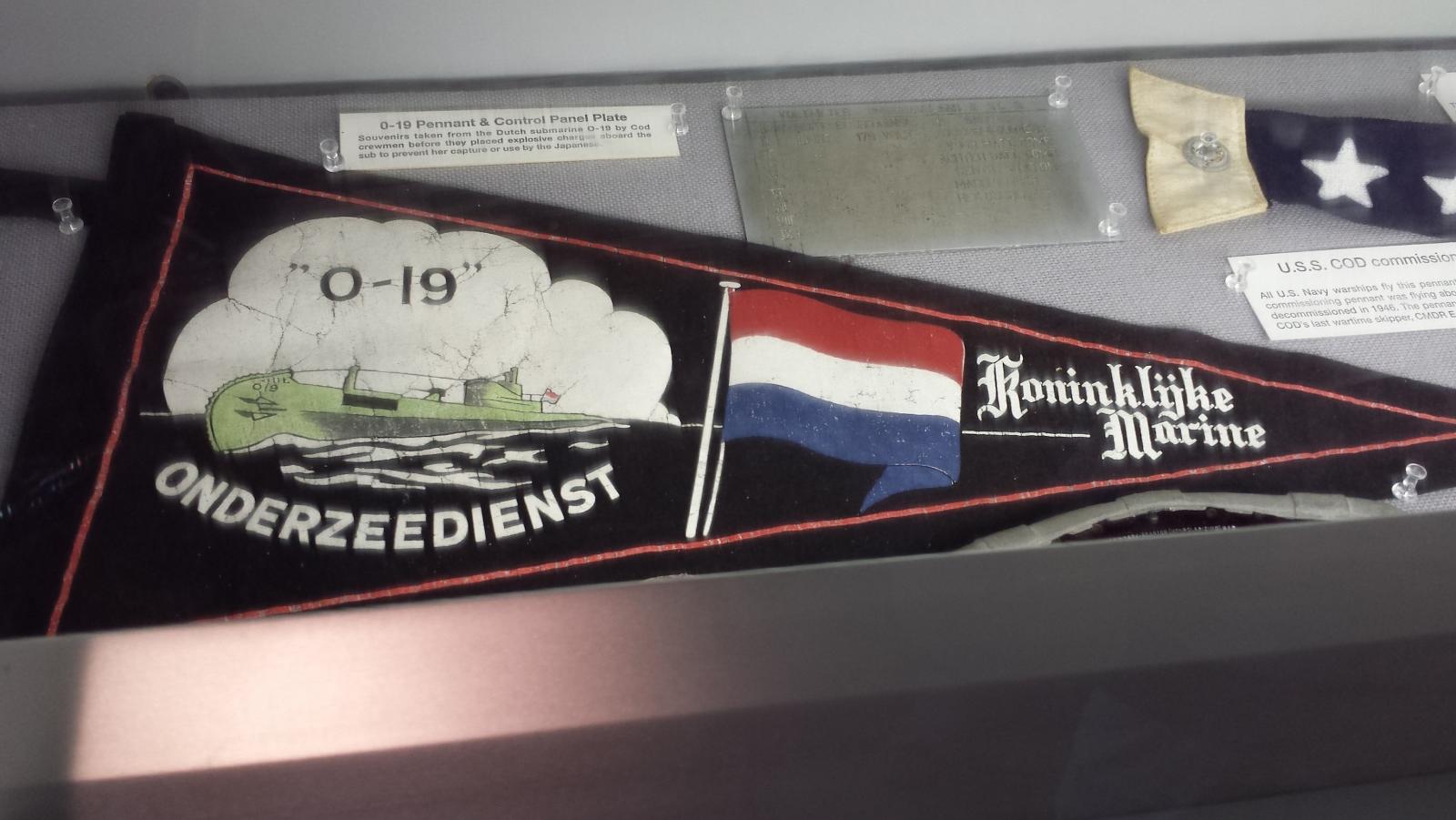
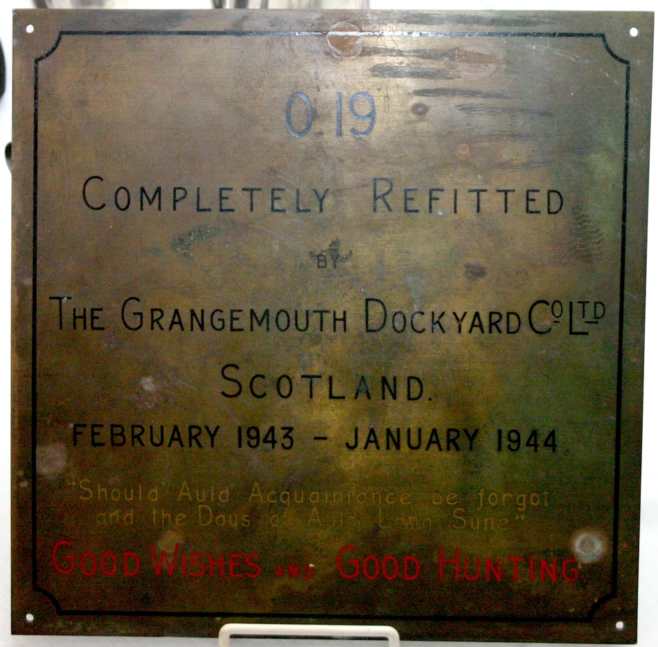
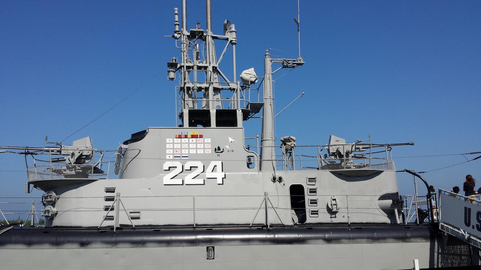
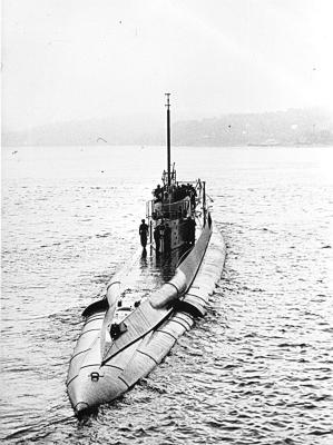
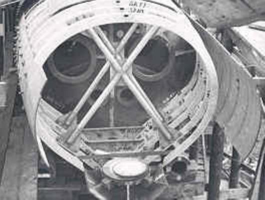
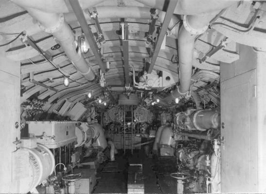
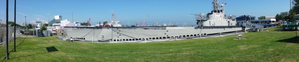
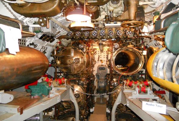
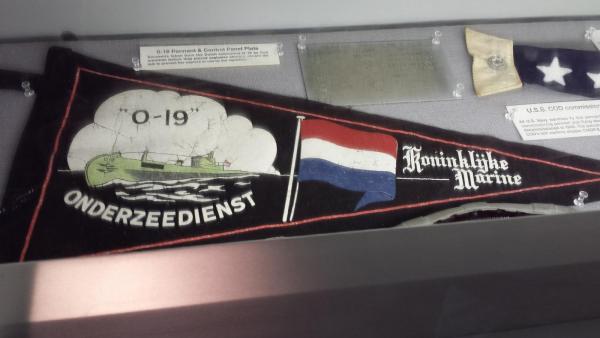
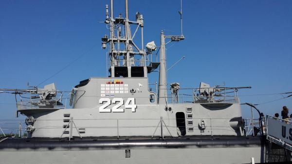
Hi Paul, Thanks for dropping in and your encouraging words, really appreciated. Yes indeed, wood can give us some problems and I did encounter a little in the beginning. But then again, I assume that paper, card and styrene can also pose a few problems. I'm looking forward to your WW I German sub build, they were awesome. Okay, we are back home now since a week from our sojourn to Coraopolis, PA, a town west of Pittsburgh, PA to visit our daughter and be present at our grandson's High School graduation. As I may have mentioned before, I planned to visit the USS Cod in Cleveland, Ohio. That sub was the one that was called to assist the Dutch sub O 19 getting off Ladd Reef. The attempt failed and the Cod took the O 19 crew on board and had to destroy my father's beloved O 19. Remember that they were in enemy waters even though the war was winding down. This event was in july 1945, thus just one month away from the end of hostilities. Because the USS Cod has a close relationship with my father's boat I Just had to go and see and touch her. So, I took my grandson Troy with me, he too wanted to see the sub. The curator, Paul Farace, promised us a special guided tour, which he did. I mentioned a few of the things my father was involved with with the build of the O 19 and some of the escapades during his early years with the KM (Royal Navy). Like when my grandson saw the torpedo tubes it reminded him of the story I told him about his great grandfather going out of his sub when she got tangled up in fishing nets when submerged. Yup, he was also a trained Navy diver and he thought nothing of it to don the "third lung" and go outside. He went through the stern tube and cut the boat loose and freed the props. Then got back inside. This was before he got married to my mother when he was a "wild and crazy guy," to coin a phrase. There is nothing like a visual image to drive a point home. Needles to say our grandson is duly impressed with his great grandfather. This is the URL with the true story of the rescue attempt by the USS Cod. Copy and paste the URL in your web browser and watch the sad end of the proud O 19. I hope you wont mind a few pics of the Cod with a few items the crew managed to take off the O 19 before destroying her. This is a panoramic shot my grandson Troy made on his dangfangeled new Samsung Galaxy 3 of the USS Cod in Cleveland Ohio. This is a picture of the bow tubes in the USS Cod. Now my grandson could visualize his great grandfather going outside his "netted" submarine. A story come alive, somewhat. This is your's truly, the Flying Dutchman, in the engine room aboard the USS Cod. These diesels still run and purr like kittens! No, they didn't fire them up for us. They have some water in the case oil, which is not too good for the bearings. However, once most of the water is sucked out then the engines should be run and brought up to temperature. This will allow the water to evaporate and breath out of the engines. That's what we do with aircraft engines too. This is the pendant from the O 19 and given to the crew of the USS Cod. This pendant was made by one of the O 19 crew members. This is the brass plaque attached to one of the O 19's bulkheads after her refurbish by the Scottish Dockyard. After the Dutch submarine supply ship was destroyed by the Japanese with all the spare parts and etc., all the Dutch subs had to be refitted to English standards so they could continue with their battle against the enemy. The so called deck torpedo launcher was also removed but they did not reinstall the doors. Traditionally the conning tower shows the ship's decorations and enemy ships sunk. You'l notice a tipped cocktail glass with the letters O 19 below it. This is to commemorate the party the crew of the O 19 gave to the crew of the USS Cod for their rescue. This was apparently the mother of all parties in the annals of naval warfare! Both boats served the allied effort with honor and distinction. Cheers.


-
Hoi Jan, Now I know for sure that I need a second lifetime What, with all the fancy scroll work Thanks Jan for reminding me to look at pictures first before I start pounding my poor head on my work bench I'm glad that you keep checking in and for your much appreciated advice. Some time ago you suggested to look at these ships, Padmos and Blijdorp, for another problem I was "pondering" on. I downloaded the pics of these two ships as well as many others. I should put a large sign over my work bench, "LOOK AT PICTURES FIRST." Okay, no gunport lids on the upper deck, hurray! Well, that solves a few problems, but creates one heck of a lot more work, fancy scroll work I wish I could afford all the books about shipbuilding, specially the Dutch ships, but alas, such is life, we can't have everything we want. We need to be extra careful now with our budget with an eye on the political situation here in the US. Hartelijk dank and cheers,