Piet
-
Posts
3,568 -
Joined
-
Last visited
Content Type
Profiles
Forums
Gallery
Events
Everything posted by Piet
-
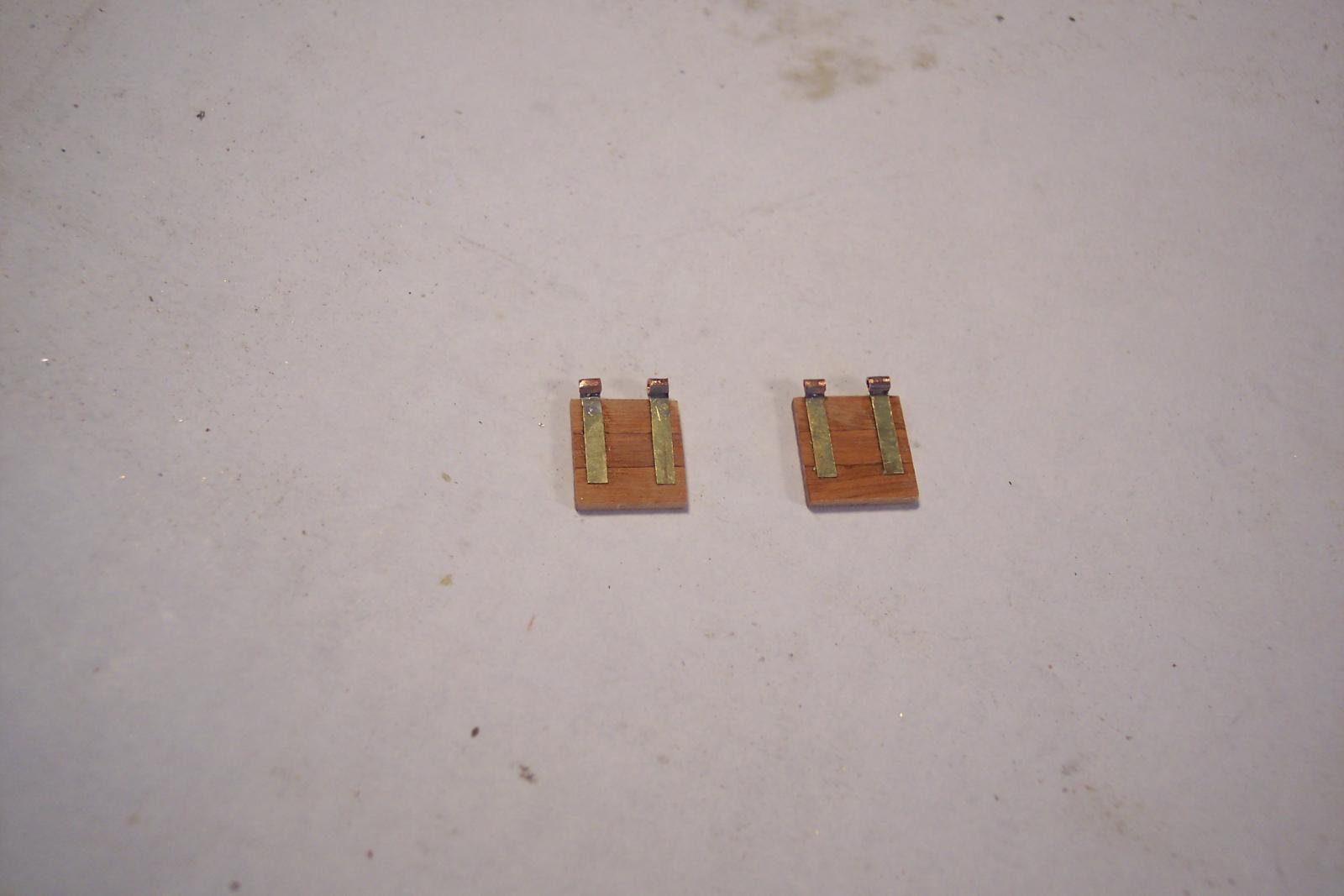
 Hey Andrieke, thanks for visiting the Surabaya! It's a fun project and I'm enjoying it much, keeps me out of the bar except the one on your river boat Well, as the epoxy is setting up on the O 19 I've been working on the gunport lid hinges and laid a couple on top to see how they look. Funny thing is that on the bench it looked okay but now looking at them on the pics they are way too large for scale. I'll have to make them a lot smaller, almost half as big. Oh well, no problem, just a few hours more "fun," filing. A few of the completed hinges laid on the lids for a look-see. Now looking at them they are a bit out of scale. I used brass sheet with copper tubing soldered to the brass strips Sooooo, some more filing to do. Cheers,
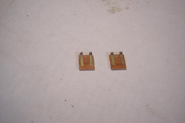
-
Hey Andrieke, nice looking stairs! And I like the decking too, great work! Have any good Belgian beer in the bar?? I'll be up shortly. Cheers,
-
Hip, hip hurray for Anja Welcome to the dark side and reserve another rocking chair for this old Dutchman And now hurry up with that Half Moon ship and finish it, soon, please Cheers,
-
Hello Chris, Hey, thanks for dropping buy and your kind words, I appreciate that. Yes, my sentiments too. I like the looks of the middle to late seventeenth century ships, both the naval and merchant ships. But, like everything, progress had to happen with lowering the poop deck and enclosed "verdek" or second deck. It made handling the sails easier and kept the crew out of the weather some. Cheers,
-
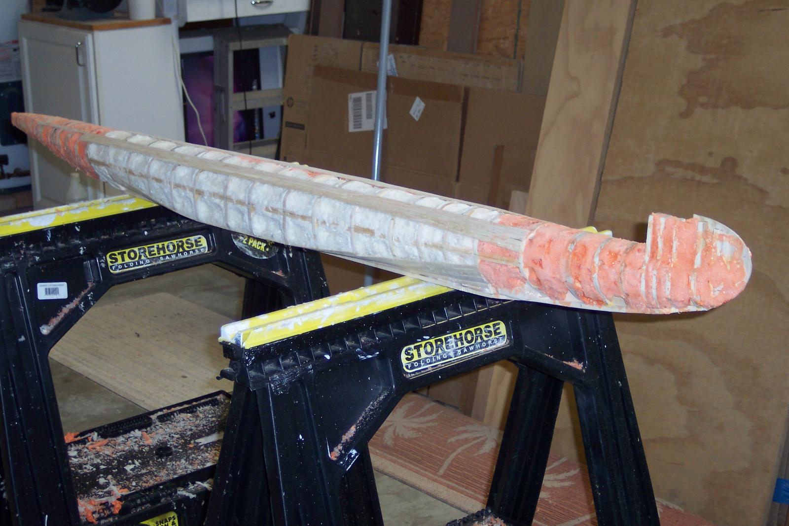
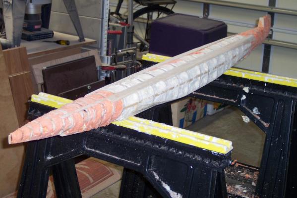
Hello Paul, Thanks for visiting and your info on the German mine laying subs. Later on in the conflict they made a few "tankers" called "Milchkuh." The O 19 and O 20 could use 4 of the ballast tanks as extra fuel tanks for long distance patrols. The polish sub "Orzel" was also a mine laying sub build in the Netherlands at about the same time as my dad's boat. The Orzel had the tubes up front, I think. My father visited her when she was being build and was duly impressed. Her gun was placed in an water tight compartment in front of the con so the crew could enter it just before surfacing and make ready to pop one off. Quite an interesting story about that sub at the very beginning of hostilities in 1940. A shame she was lost in 1941. No one knows why and how, no records of her loss. Well, I have put the Dacron fabric on the hull today. Had to work like mad to stay ahead of the short pot life of the epoxy resin. I used 1 oz per side, which was comfortably enough. Had to make sure that everything was prepped but it worked out okay. It gave me also some time to devote on the VOC ship. I managed to make a few more gun port hinges, am up to 22 out of the 32 total. Making progress. Tomorrow is sanding the epoxy and see if I need Bondo to fine tune the shape. This process takes me back to my aircraft repair business in New Jersey. Besides regular maintenance and engine overhaul and avionics, autopilot installations we also repaired wrecked aircraft, either for a customer via insurance bids or we bought a wreck on speculation and rebuild them for resale. Lots of fiberglass parts to repair. In any case, below are a few pics of the process. I have pinned the edge of the Dacron fabric to the top of the hull and let it fall down the side. Now I can see where I need to cut the fabric to compensate for the compound curves. It's enough to cause wrinkles if I don't cut the fabric in specific locations. On the starboard side I waited till I had the fabric epoxied to the hull. This way I know where to precut the fabric on the port side. It worked as advertised. Here I folded the fabric back over the top to prepare for the application of the epoxy resin. I first epoxied the top of the hull then folded the fabric over it and with a small brush I added more epoxy to the top of the fabric and smoothed it out. Then I put the hull on its side and worked the rest of the fabric towards the keel. I had to let this harden up before I could do the port side but that gave me the time to work on the VOC ship gunport hinges. I managed to make another 8 pair and have now about 21 or 22 of the 32 needed. Well, at least it's some progress This is the starboard side all epoxied up and curing. It'll be at least 8 hours before I can actually use sandpaper, otherwise the sandpaper will just clog up.Tomorrow is sanding time and then we'll determine whether I'll have to use Bondo, most likely , yes, just to be on the safe side. The overlap areas do leave a small ridge and there are a few small areas that can use some more filling. Overall I'm pleased with the results. Cheers,
-
Hello Lawrence, Thanks for the visit and your compliments, really appreciated. Like I mentioned in my PM to you I'm pretty much bound to building models the hard way, draw up my own plans. Now that I am retired at a rather late age, my income is drastically reduced and must be careful in expenditures My professional background is in aircraft maintenance and engineering. Aircraft fuselages and ship hulls have a lot in common and once you have a fairly good idea about the shape of the hull, via many drawings and paintings, then it's really not too difficult. Did you visit my submarine build log? That project has pushed the VOC build on the back burner. But there are moments between waiting for glue to dry or other things that I can devote some time on the VOC ship. Right now I'm working on the gunport lid hinges and have already 21 pair done of the 32 total. Time consuming work but a fun project. I'll have a few pics in a day or so to keep this log active. Cheers,
-
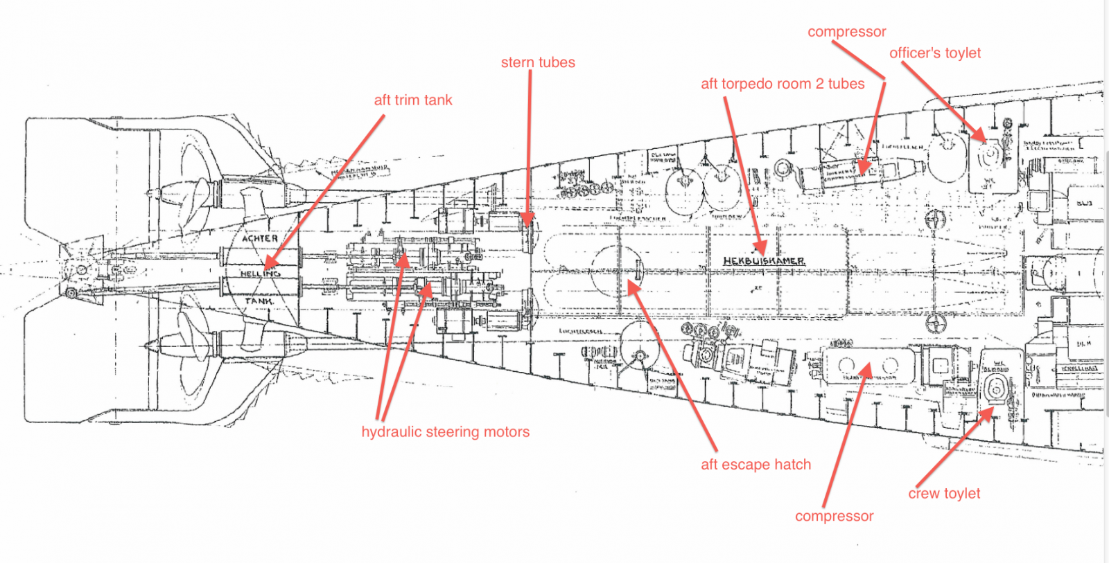
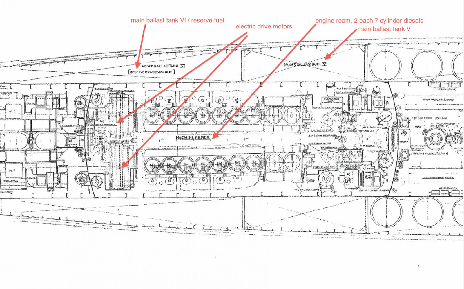
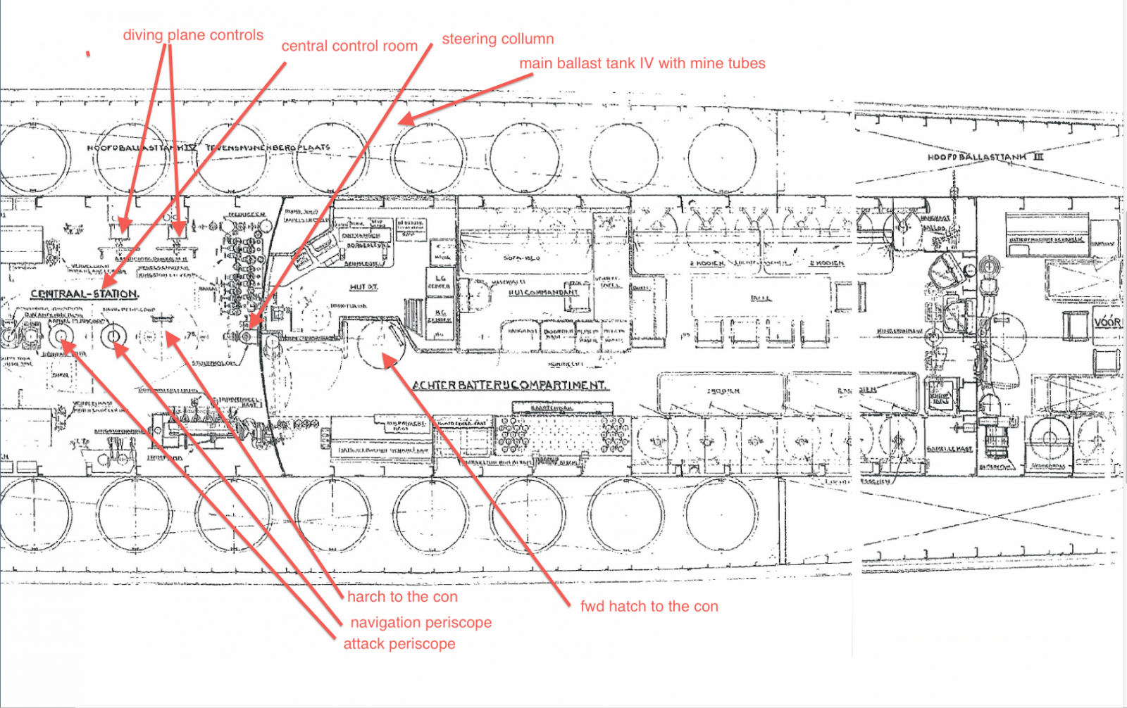
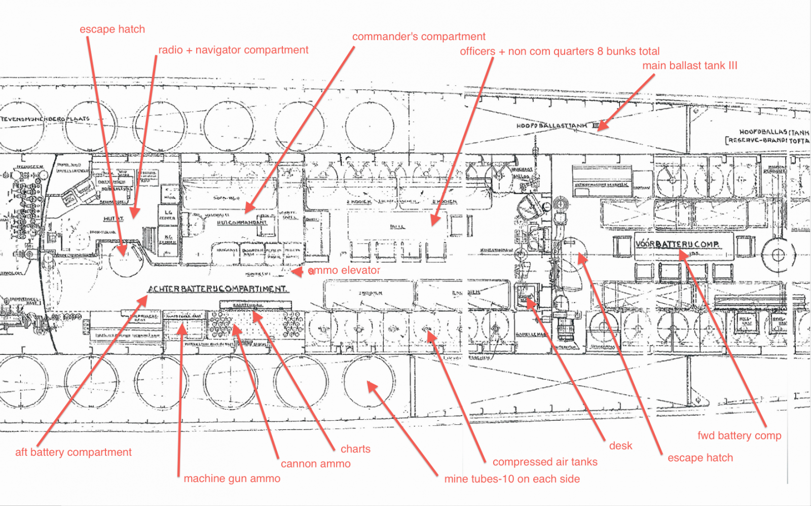
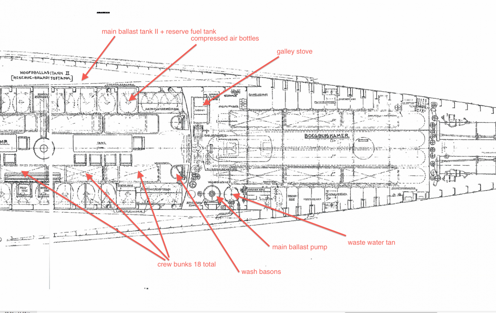
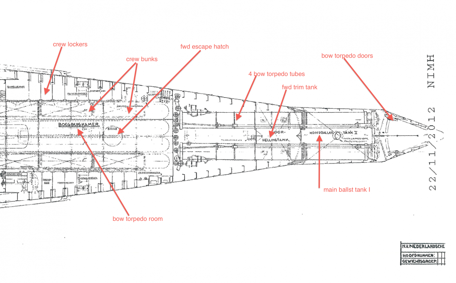
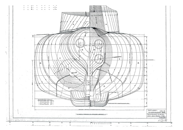
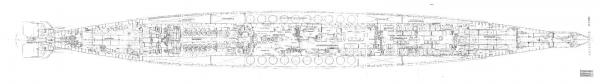
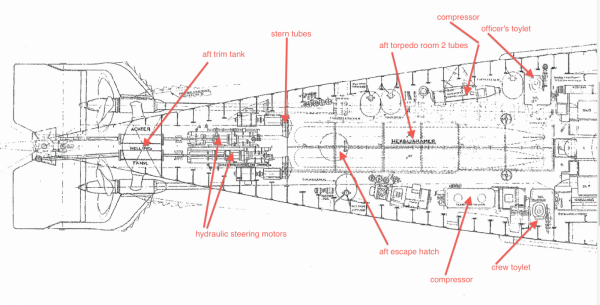
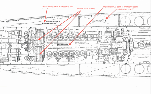
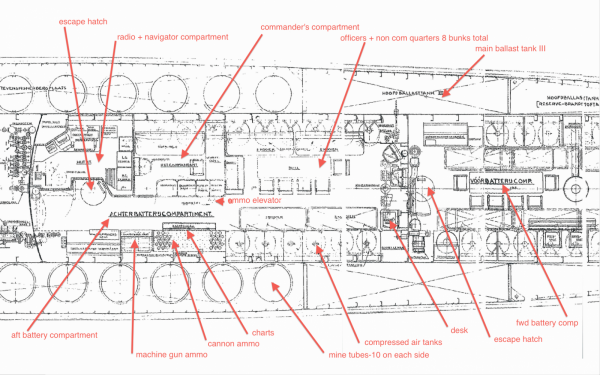
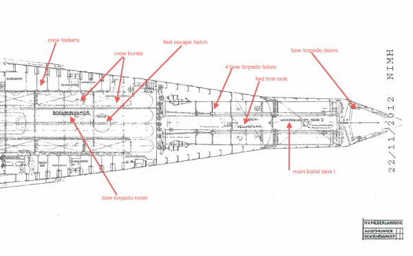
Well, today was going to be the day for doing the Dacron cover with epoxy resin but - - - dummy me, I forgot to buy latex gloves. That stuff irritates my hands now and I don't like to suffer for two weeks. So, I did some work on the VOC ship. I made seven pairs of gunport hinges, that's 7 out of 32. Will be going to the store tomorrow for the gloves and some wood for the O 19 deck structure. But, I extracted a copy of the interior view of the O 19 from my files with some of the areas identified in English. I thought yuns would like to see how this sub looks like inside. Hey Kevin, any resemblance with the boat you served on, besides the mine storage areas that is? The first drawing is a JPG file I received from my friend Gino den Ridder. I would have preferred to attach the PDF file it is much to large for here but is clearer. Gino is the assistant curator for the USS Cod that rescued the crew from the O 19 when it ran onto Ladd Reef July, 1945. The USS Cod is in Cleveland, OH as a museum piece and is fortunately not butchered up with a cut in the pressure hull for stairs to go below. I'm looking forward visiting the USS Cod and the promised grand tour. This shows the entire boat. The following 6 pictures are enlarged screen shots from the different areas, starting with the stern. Cheers,


-
Hey Kevin, I understand the conditions on these old boats and not very comfortable in any kind of see. Talking about rough weather, my father told us about them getting caught in a typhoon in the South China Sea. The "old man" took the boat down to below the wave action and told everybody to lay down and rest. They shut off most everything electric and just waited a while, a long while. When they had to surface the seas had calmed down quite a bit and continued on with their mission, checking up on the Japs. @ Boris, great, good to hear and hope they are useful to you. Glad to be of service. @ Sjors, thanks for making the pics for me, I really appreciate it. According to Google Earth that little plantsoenetje is still there though and that has also some memories. I won't go into detail about one episode but it entailed playing nurse and patient. The neighbor girl being the nurse who wanted to take my temperature. Well, I was not very gentlemanlike and bobbed her one. Yeah, I know. Travel across the pond is expensive, that's why we don't do it anymore. But one never knows, the Admiral would still like to visit her sisters but I really have no need. Hey, there is more to the USA then Mesa Verde We have a gezillion spectacular places to visit and besides all these beautiful places we have a hole bunch of great MSW members who like to have you come and quaff a few Warsteiners and I'll even make a bunch real authentic Indonesian snacks too!!!! Yum, yum, yum. You'll need a few years vacation and bum off of everybody for room and board Cheers,
-
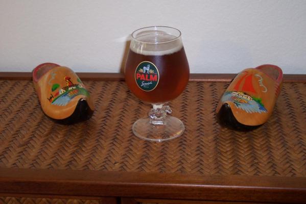
@ Andrieke, just in fun my friend. Homesick? Nah, Oz is good with some good beer as well. Yeah, I was lucky to get a Palm glass. When I had to go to the Netherlands for Uncle I visited my niece in Bergen op Zoom and her husband and I would buy a sampling of several Belgian beers. He has quite a selection of matching glasses for many of them. I really enjoyed those times. @ Sjors, where have you been man, I had a special Lazy-boy chair set up for you with your favorite brew. Glad you made it to my build log and come anytime for a visit. You can go visit Mobsie but what am I, chopped liver? But in order to come and visit us you'll have to use an aluminum sewer pipe called airplane. Yes indeed, submarines like to use a low profile , not that they are shy, just sneaky I also know that W F is in Schiedam, see paragraph 4 of my intro. I should have added the word "near" in front of Rotterdam. May have to revise it, someday. Well, when we lived at 3 Narcisplein in Vlaardingen Ambacht, the Anthony Knottenbelt Singel from the Goud Singel south was a water ditch (sloot) with meadowlands next to it as far as the eye can see. There was a narrow footpath next to it behind the houses. That little open space next to the Goud Singel was our play ground then. Wow, things have changed a lot. I will certainly appreciate a few pics of # 3 Narcisplein and that little "plantsoenetje" in front of our ex house. I remember chasing the ice cream man in the then existing Anthony Knottenbelt Singel on my "autoped." Pics of W F would also be nice, all visible memories. I do visit Holland a lot via Google earth, at least I can afford that nowadays. Since my retirement no more trips to the Netherlands for Uncle Sam. @ Paul, thanks for visiting Paul, I have extra chairs set aside for yuns ship crafters. At least my boat is also iron like yours Aren't you building a WW II U-boat of plastic? Not exactly a WW I cruiser but they didn't change much. Hmmm ballast tank inlet ports, well, how do you suppose they can go under water? Duh! Pretty much everything outside the pressure hull was tanks, either for water ballast and/or extra fuel. She had also what they call trim tanks in the bow and stern area. Like Kevin mentions, she could be rock solid on the ocean floor with all tanks flooded. This reminds me of an incident my father told me about when one of the subs he served on got tangled up in fishing nets and couldn't move up, down, forwards or backward and they were quite a way down from the surface. He got her freed up though. Some big brass &%#(* - - - - I'll show a picture of the interior arrangement very soon with hopefully some explanations in English. Not everybody here can read Dutch, pity. @ Kevin, thanks for looking in and helping out with sub technicalities.
-
Awesome! Looks very nice my friend. I'll give a toast with a Palm beer on the results and your recovery with whatever ails you. Cheers,

-
Hey Andrieke, Perhaps not as quick as I would like but I made the body plan drawing to scale 1:50! It's a start. I'm still tweaking the hull with wood filler stuff, I keep finding little valleys and other imperfections. Tomorrow is a day off for me from the shipyard so perhaps Sunday I start cutting the Dacron fabric for the hull. I have to work fast because the epoxy resin pot life is not very long. I'll mix small badges so I won't waste much, the frugal Dutchman in me Okay Andrieke, here is to your health, I just poured myself a nice cold Palm beer. Proost! Cheers,
-
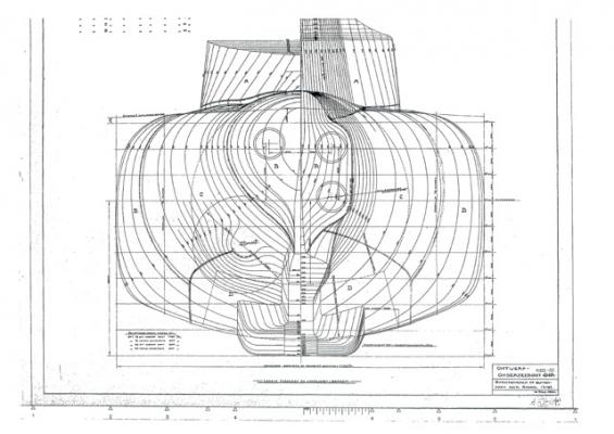
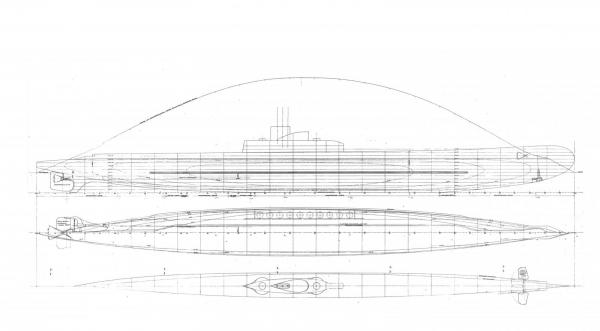
Hello everyone, Thank you all for your likes and comments, really appreciated. Jim, yes, she is looking like the photos I have of her sitting on the skids [slip-way] at the shipyard. Randy, thanks for joining my build and pull up a chair and help quaff a few good Belgian beers Andrieke, thanks for looking in and btw, the Admiral just bought a 6 pack of Palm beer! They are finally stocking it in the local supermarket in our little hick town. Augie, if I keep tweaking the hull as I'm doing now you may be right but I won't bet on it though. This pm as I walked by from the mailbox the light must have hit just right and I noticed a few areas that need some shaving of wood. The harder grains don't sand down as easy as the adjacent softer grans, even when using a long sanding block. Even at a scale of 1:50 minor imperfections will be very noticeable and I want it to be right. Elmir, thanks for stopping by for a look see. Yes, my father loved them. My whole working life I worked on another kind of metal tube, airplanes and flew them as well. I would give my newly implanted eye tooth for a ride in one. Well, today I took a day off from the shipyard for another project. However, Now I need to draw up the deck structure frames and will have to spend some time at my drafting table. Below are copies of the original lines for the deck structure but they are of unknown and different scale. That'll be fun So, all y'all wish me luck with that endeavor. This is the original body plan for the mine laying submarine designated as O 17. This plan was drawn up by the Koninklijke Marine [Royal Navy (Netherlands)] in 1934. It was revised with a flatter bottom to accommodate 2 mines in one tube, 10 tubes on each side, making it 40 mines. The only part I can use are the deck lines. These are the sheer, half-breadth and deck plans for the O 19. I used these lines before with the modified body plan of 1936 for the hull frames. It should not be too difficult to draw up the deck frames, he says with full confidence . Cheers,
-
Ah, glad to see you back at it Remco! How's the Admiral's table coming along? Cheers,
-
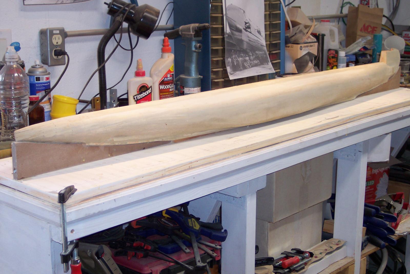
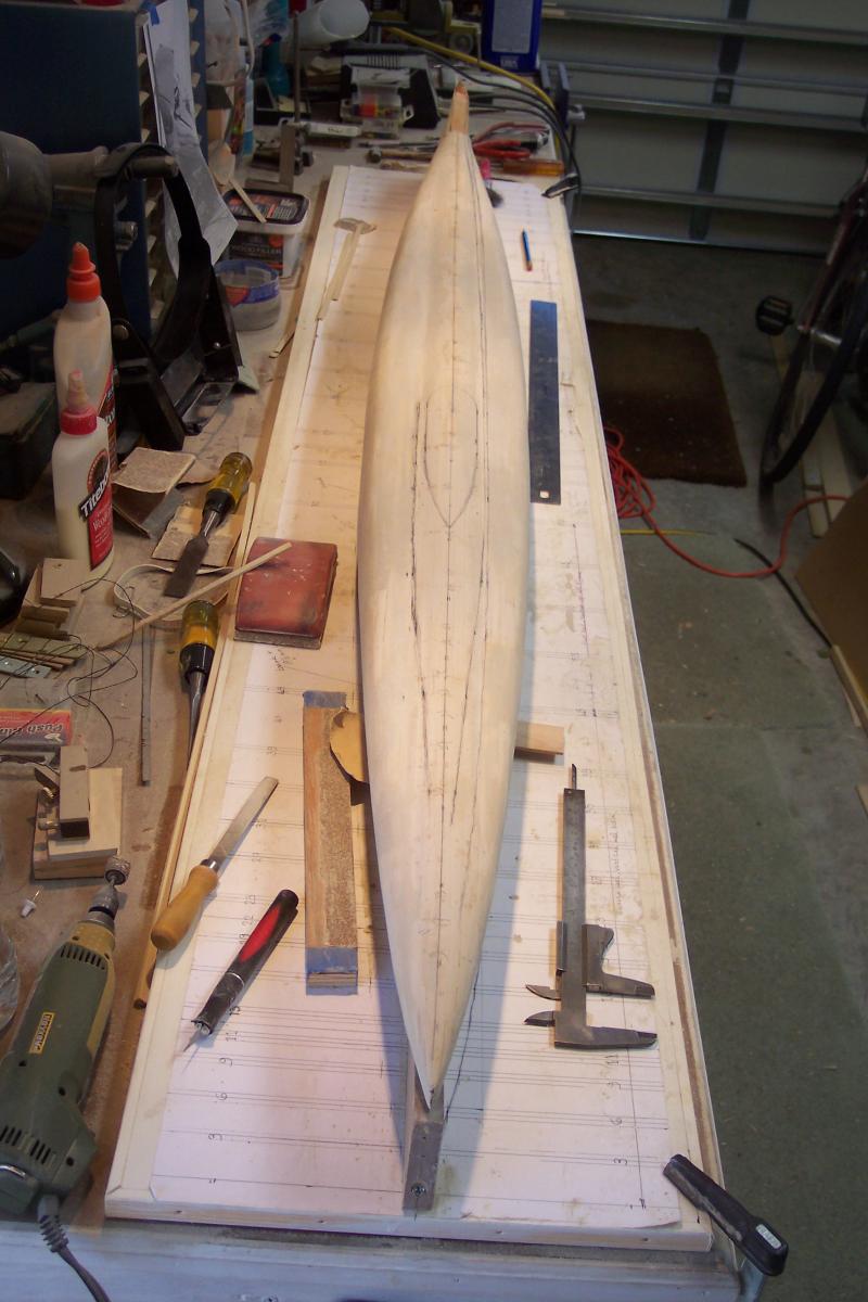
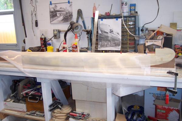
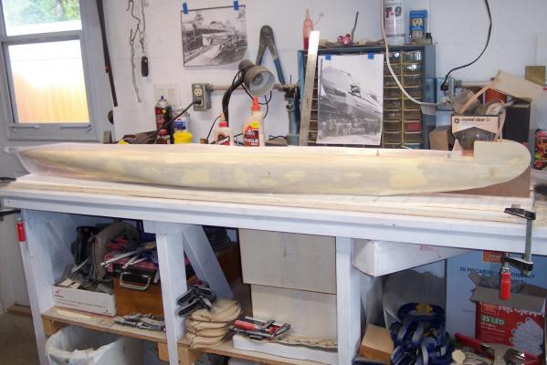
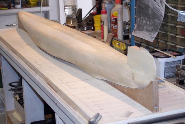
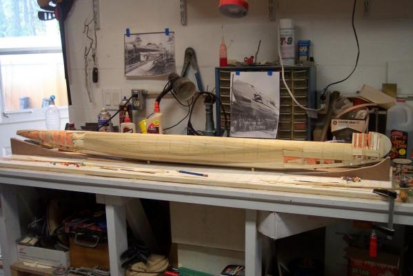
Hello all y'all shipwrights, There are festivities at the Flying Dutchman's shipyard!! The entire hull of the O 19 is now closed in with the base planking! I put on a CD with the Mariniers Kapel and poured myself a good Belgian beer, Trapist I also smeared wood putty over the hull and sanded it down. I like that word, smear, reminds of the Dutch word "smeren." Is better then spreading, that's so proper. I'm still nit-picking at at several locations but overall she looks quite good and even to me. The biggest problem I found is that there is too much spacing between several bulkheads and the thin planking has a tendency to sag a little in between. The foam was not much help and in retrospect I should have made more bulkheads. However, the sag is VERY minor, estimated at a cat's whisker. It didn't take much filler to bring the hull to proper contour. I'm now almost ready to glue the thin Dacron cloth to the hull with epoxy resin and then correct any imperfections with either bondo or acrylic paste. I don't like bondo that much, it has a rather short short shelf life once mixed with the hardener.. The acrylic paste takes a lot longer to cure and is nice and pliable. I used that stuff in painting pictures with acrylic paints. The artists among yuns understand what I'm talking about. I couldn't help myself in drawing the outline of the deck on top of the hull. I'm also looking for a drawing or photos of the little sloop that was stowed blow deck aft of the con. I only have two photos of that thing but it's difficult to use for a model of it. Next step is drawing up the deck structure frames. This time I'm going to make enough frames but i'm using 1 mm plywood for the covering that should be rigid enough, I hope. Okay, here are a few pics of the current status. 3/4 starboard side view of closed hull with some of the sanded down wood filler. As mentioned above, the final finishing will be done after the Dacron cloth is put on and before gluing the fake steel plates made from paper. A view from the stern. A view 3/4 from the bow. The prelim lines of the deck and conning tower location. Cheers,


-
Y'all is in the singular and all y'all is plural Cheers all y'all,
-
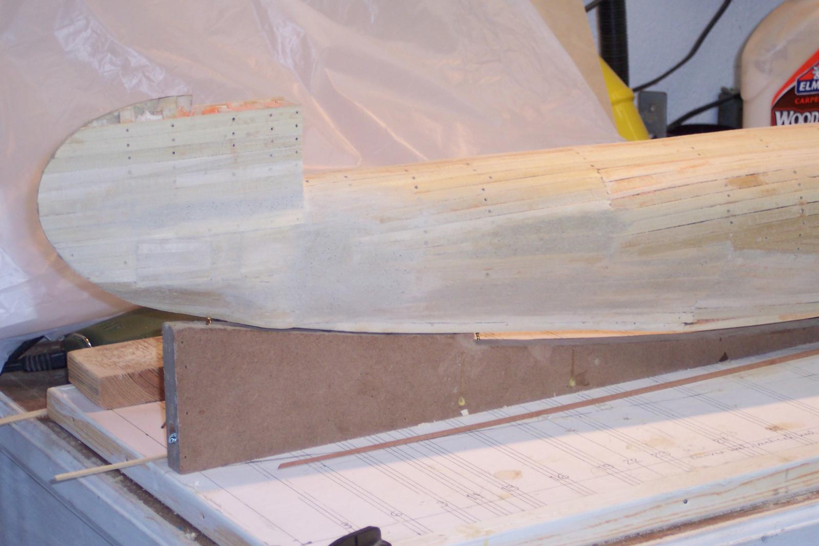
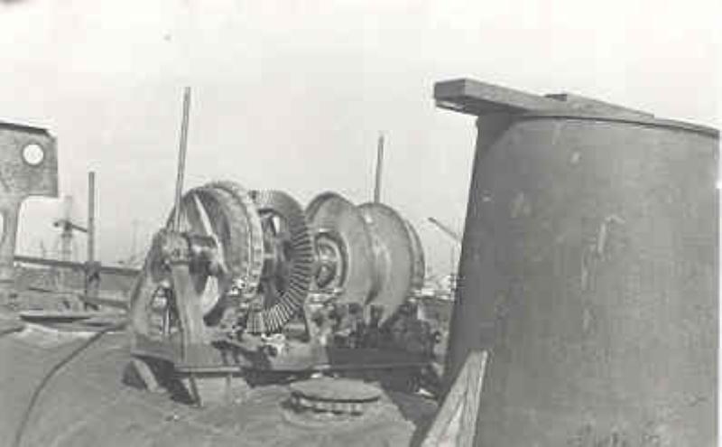
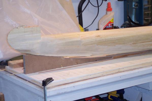
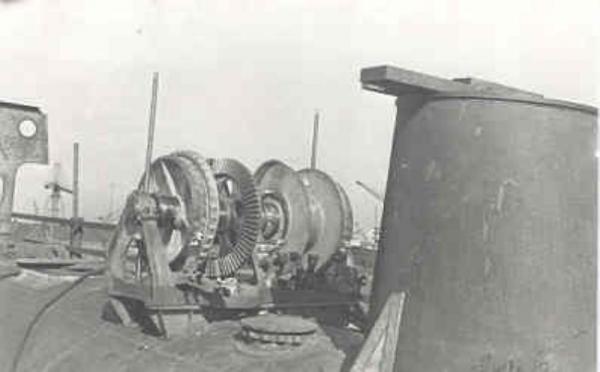
Hello all y'all shipwrights, Drum roll please - - - and open a bottle of the bubbly the bow section is now closed with the base planking!!!! I have also started to put some wood filler on the planks to see how she is shaping up. So far it looks pretty good, very minor areas to fill but necessary for the next stage with the Dacron and epoxy resin covering. I may have to do a final treatment with bondo or a polymer paste before I can put the paper "steel" plates on. Below are a few pics. Close up of the closed bow section port side. That rounded thingy on the bottom is the location of the "mushroom anchor" (paddestoel anker in Dutch). The anchor mechanism to lower it and raise it was mounted on top of the forward pressure hull and under the deck structure. See next picture. As stated above I added some wood filler to smooth out the planking and cover some of the divots and unevenness. This is the anchor mechanism (ankerlier in Dutch) shown mounted to the O 19 when it was being build. That big round tubular thingy is the escape hatch in the forward torpedo room. Another picture of the port bow. looking forward over the top of the hull with the raw planking in place. You can see the rounded portion of the pressure hull in the center with the extended sides for the mine tubes. Just the stern to be done now! Looking aft from the bow. Yes, still some dressing up to do. The bow will get the cable and net cutter as the original boat had it. I hope you can see the torpedo bow doors, them the things that angle in forward. Cheers,


-
Thank you all my dear friends, your comments are appreciated and encouraging. Remco, the only thing I plan to add between the upper hull and the deck is the side-launch torpedo tube assy. There are also outside torpedo storage areas aft of the bridge but that's only indicated with lines of the lids. They kinda get lost between de teak deck planking. The stuff on the deck is already time consuming as is and more important. Just aft of the con was a small dingy stored below this deck, hmmm, maybe? I'll have to wing it for the shape because right now I have no drawings. I'll ask Gino den Ridder if one of his buddies in holland can obtain one or photos. re the upper bow structure, yes, the deck structure fastens to it and will become flush. These Dutch subs had a rise of the deck going forward, kinda nice looking. Well, this is it for now. I have added a few more planks today! Once I start putting the wood filler on I can do some work on the VOC ship between wood putty drying time. Gunport lids is the VOC project. Cheers to all,
-
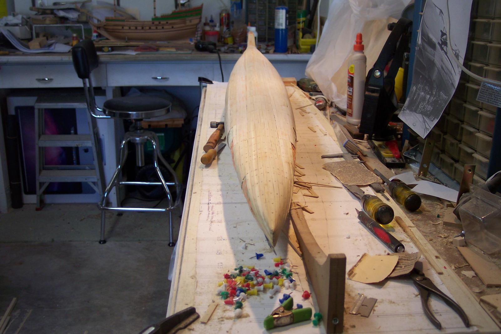
Hello everyone, It's been a few weeks since my last post but that doesn't mean I've been sitting on my hands. I've been busy as a beaver. To get back to the topic on flags and colors. Jan is correct as far as no standardization of flags but the colors is rather interesting. The orange dyes used in the early years was a mix of red and yellow dye making it orange. However, the yellow was not color fast and faded over time leaving the red. I heard fairly recently when listening to a Dutch radio station for music, that Queen Beatrix ruled that red was officially the color of the top band in the national flag. Now back to the O 19 build. I didn't want to clutter up this log with a gezillion photos of me planking the hull. We all know how that goes but I'd like to show a little progress picture for yuns to see how she is coming along. The reason for the slow progress is that now I have arrived at doing the bow and stern sections with plenty of compound curves that require me to cut the planking into narrow strips, wetting many of them, bending to fit, clamp them in place, letting them dry and then finally gluing them on. I can only glue a few at a time working at both ends at the same time but even so it is slow going. I have been filing and sanding the center portion as I'm waiting for the glue to take, at least one hour before I can remove the push-pin clamps. I have to be careful with the sanding because the planks are only 1.5 mm think. I also need to use some wood filler in areas where I have some unevenness and divots. So far I'm pretty happy with the results I see. The plan is that after the hull is planked and evened out with wood filler I'll cover the hull with a VERY light Dacron fabric and epoxy resin before I use the heavy paper to simulate the steel hull plates. There are areas that need to be moulded with either the wood filler I have or bondo to simulate the forms I see on the photos of the boat. The bow doors are a case in point. After the hull is done to my satisfaction I'll start with the deck structure and perhaps make one of the mine tubes visible with a working top lid. I'm not gong to to make the torpedo doors workable, too much involved Okay, enough of my banter and here is the picture I took today late afternoon. This shows the present condition of the O 19. Both sides are at about the same level of closure. The top is completely closed in now. The dots you see are the push pin holes I use to "clamp" the planks to the frames, works like a charm. I attached two of the photo's I have of the O 19 to the wall and hardware bin to help as a guide. These photos were taken as she was just before the launch in 1939. My father is amongst the crew photo on the right. Here you can see how many curves there are and it'll be a dog to simulate them all. Well, at least I don't have to carve lions, dolphins, trumpet blowing angels, knight heads and what have you. It would be funny though to have a roaring Dutch lion on the bow Cheers,
-
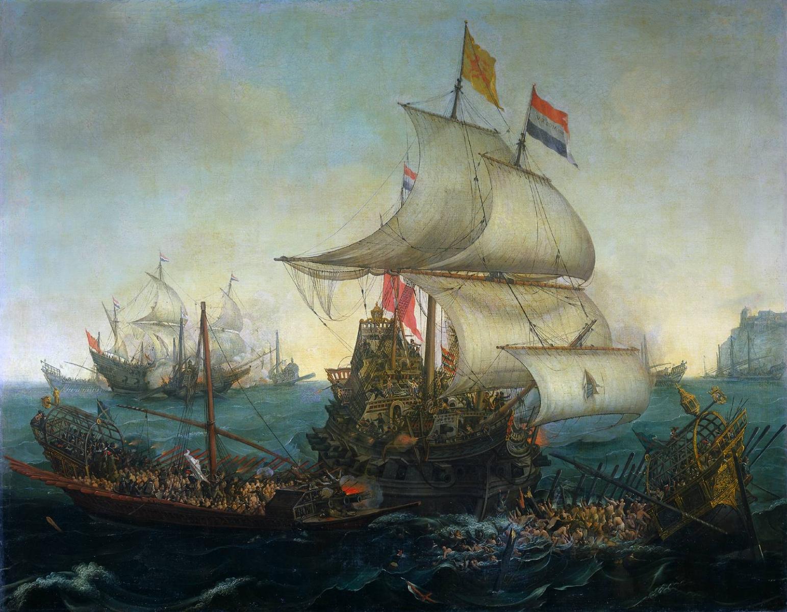
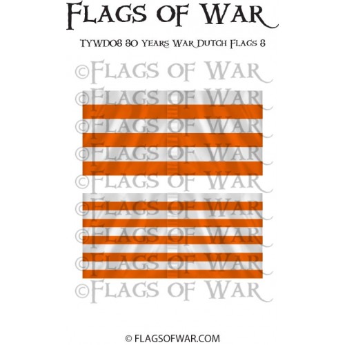
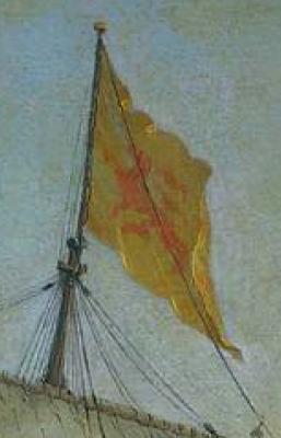
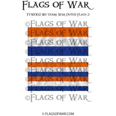
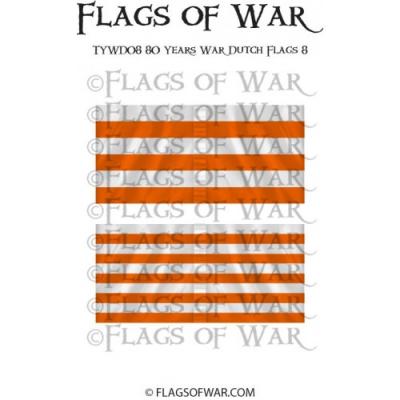
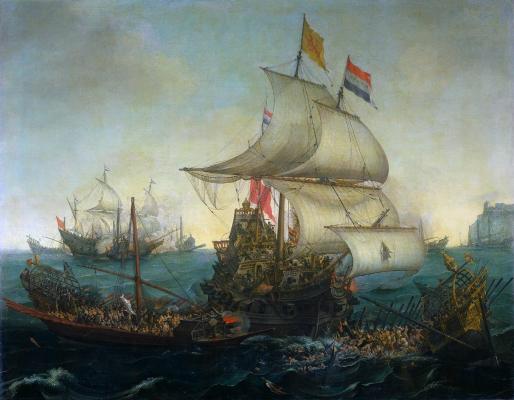
Update on battle flags. There are 8 battle flags used during the eighty year war with Spain. I won't show all of them, this can easily bee Googled. The flag Anthony showed, the yellow flag with a red lion holding a sword is not mentioned anywhere but no doubt used in the Seventeenth Century. According to several paintings it is prominently flowing from the top of the mainmast. Attached is a copy of a painting from 1602, still in the years of the Eighty Year War, with the golden colored flag with the red lion of Holland. Ill attach only two pictures of the Eighty Year War battle flags. I'll also attach a picture of the current Koninklijke Marine (Royal Navy) pendant (Jack). Dutch ship running down Spanish gallyes, 3 Oct 1602 detail of the "Battle Flag." Eighty year War battle flag 1 Eighty year War battle flag 2 Royal naval Jack. Cheers,


-
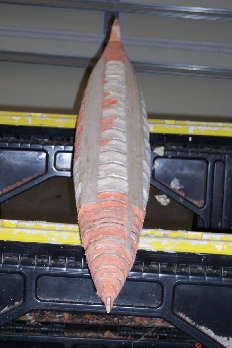
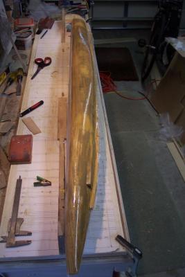
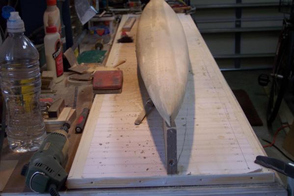
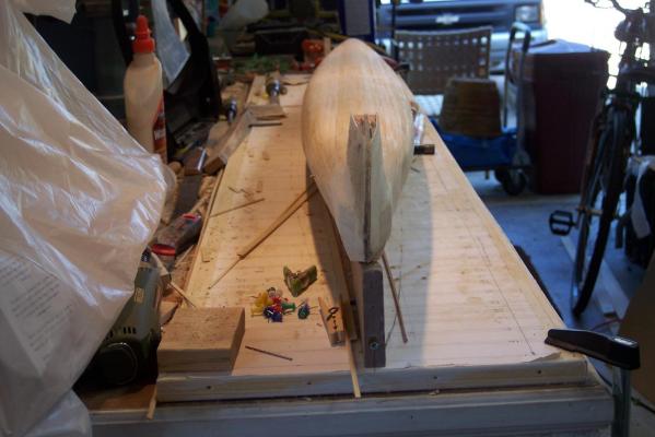
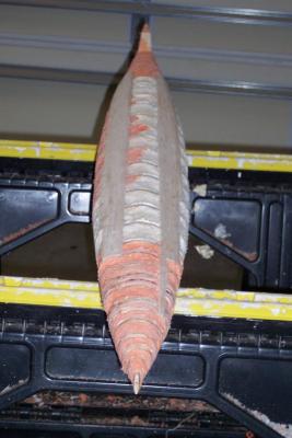
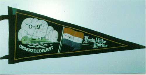
Hello fellow shipwrights, As I mentioned early in my log the O 19 ran onto Ladd Reef in the South China Sea July 6, 1945. The American sub USS Cod was dispatched to help and see if they could pull the O 19 off the reef. All efforts failed and the crew of the O 19 was taken on board the USS Cod. They then commenced to destroy the O 19 with demolition charges, gun fire and two torpedoes. Well, it so happens that the USS Cod is mored in Cleveland, OH and the admiral and I will be in Pittsburgh, PA to attend our grandson's High School graduation in June. I'm planning to take a drive to visit the USS Cod for a tour and chat with the curator. Unfortunately I can't make it for the July 9 O 19 commemoration day. But there is always next year. I also have been in touch with the assistant curator of the USS Cod who is sending a bunch of photos and videos of the O 19 and also the rescue operation. I hope to see my father on one of the photos, keep my fingers crossed. In the meantime I have filled the O 19 hull with foam to give the planks support from the inside but I first glued fiberglass patches with epoxy resin to the underside of the planks already installed. That really gave the planks a lot of rigidity. It was a real messy procedure but am glad it's done. Now I can continue with gluing all the planks to the hull. The bow and stern parts will be last because of the peculiar shape of the hull bottom. I'll have to study the photos real good with the body and sheer plans to get an idea how the shape flows. It's all because of the extra width of the hull due to the mine tubes. Here are a few pics as the model looks right now. Not very pretty but it'll all be covered with wood. The O 19 hull filled with styrofoam seen from the quarter starboard side. I ran out of the can with the white stuff and had to take a run to the store for another can and just picked one off the shelf. It turned out to be also fire resistant foam. A befitting color for a lady The O 19 hull filled with styrofoam seen from the quarter port side. The O 19 hull filled with styrofoam seen from the stern. Now you can see the form taking shape. We were talking about flags a few posts ago, here is a picture of the Pendant of the O 19. Cheers,

-
Anthony, thanks for the picture, I must have a larger version somewhere in my archives and make a flag when I get that far. Seems like a capital idea because my ship is supposed to be hybrid anyhow, a heavily armed merchant ship that could double as a third rate. I like the idea. Now, depending on what year, the top orange band changed to red. Right now i can't recall when that occurred. I'll have to remind myself to use the correct color for around 1665. I am ver slowly working a little on the VOC ship. Making gunport lid hinges and then hanging them. The O 19 seems to be more pressing at the moment. Boris, I received your e-mail message and I'll be working on your request. I don't know if the local print shop can handle the outsized pieces of paper. We'll see. Otherwise I'll go to plan B. Cheers to all,
-
@ Anthony, thanks for your bday wishes. Actually I like the old sailing ships myself but the O 19 is a special project for me. In my past life i started to study for ship's machinist and obtained 13 technical trade certificates in that field but then switched to aircraft design engineering. Never obtained a degree in the Netherlands due to let's say "political circumstances." So I decided to emigrate to the USA but worked for a year as aircraft mechanic for KLM in Amsterdam while waiting for my visa and green card. In any case, my entire working life has been aircraft. Hey, I need to get me a Dutch battle flag, I can hoist that up on my VOC model It has enough cannons to double as a battle ship. @ popeye, yeah, different alright even with the Scharnhorst and Bismarck, at least it's steel I am still thinking about doing the plastic kit of the Polish boat "Orzel." My father did visit that thing when it was being build in Holland and was duly impressed. Someday I'll have to find the kit. The German U boats did look more like sharks in my opinion. Read up a lot about them, also a long story behind it from at the end of WW I when suddenly a"Dutch design bureau" came into existence. The German engineering was superb as well as with their aircraft. @ Boris, thank you for your interest in my build and I send you a personal message. There are no electronic drawings, I have just a few on large sheets of paper. I do want to help you with your quest though. Cheers,
-
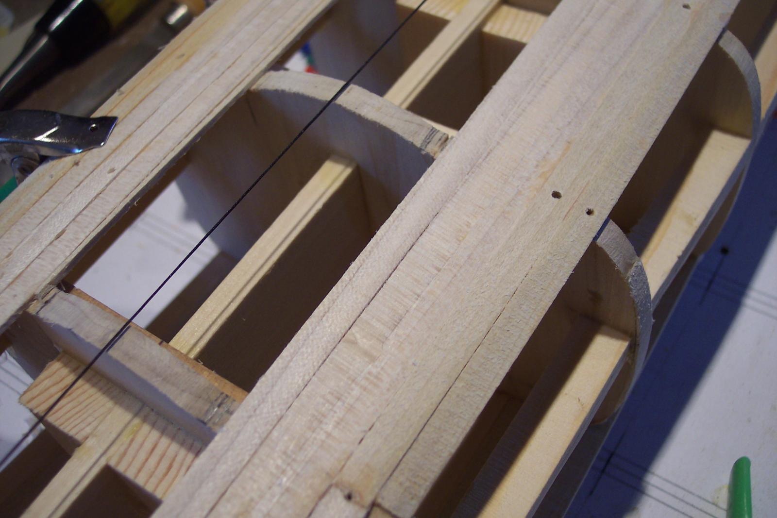
Hello fellow shipwrights, Yesterday, on my way back from my birthday party held by our financial advisor, I stopped by at "Hobby Lobby" in St. Augustine and bought some needed "stuff." I got a few blocks of balsa and 300 lbs cold pressed watercolor paper. It's nice and heavy, close to 0.4 mm thick. Just what the doctor ordered for the simulated steel hull plates. I'm a happy camper. Today I stopped by the local Home Depot and got wood filler and epoxy resin with fiberglass cloth. I found that I really need to reinforce the planking on the inside to give it some more stiffness. Even with the planned styrofoam it is still too spongy to my liking but that's the breaks in this business. Trying to safe weight by skimping on bulkheads and now I have the extra work to do. But hey, I'm not going anywhere and this way I am assured of a good solid hull. This afternoon I did some fine tuning on a few bulkheads that were not quite right by adding some veneer strips. Even the long steel straight edge didn't catch it. But that's okay, you can't win 'm all. I made a closeup pic of the upper starboard planking over the main ballast tanks. No remember that these still the raw planks without sanding. The holes are for the pushpins to prevent the planks from splitting. This just the base planking, they will be covered by the heavy paper and polymer adhesive. Closeup of center top starboard planking over the main ballast tank/mine tube area. The holes are for the pushpin "clamps." These are 1/4 inch wide by 1.5 mm thick poplar planks and you can see there is quite a span between bulkheads. 2 mm planks may have given me the desired stiffness but then I'll be outside my scale. Cheers,
-
Hello fellow shipwrights, Yesterday, on my way back from my birthday party held by our financial advisor, I stopped by at "Hobby Lobby" in St. Augustine and bought some needed "stuff." I got a few blocks of balsa and 300 lbs cold pressed watercolor paper. It's nice and heavy, close to 0.4 mm thick. Just what the doctor ordered for the simulated steel hull plates. I'm a happy camper. Today I stopped by the local Home Depot and got wood filler and epoxy resin with fiberglass cloth. I found that I really need to reinforce the planking on the inside to give it some more stiffness. Even with the planned styrofoam it is still too spongy to my liking but that's the breaks in this business. Trying to safe weight by skimping on bulkheads and now I have the extra work to do. But hey, I'm not going anywhere and this way I am assured of a good solid hull. This afternoon I did some fine tuning on a few bulkheads that were not quite right by adding some veneer strips. Even the long steel straight edge didn't catch it. But that's okay, you can't win 'm all. I made a closeup pic of the upper starboard planking over the main ballast tanks. No remember that these still the raw planks without sanding. The holes are for the pushpins to prevent the planks from splitting. This just the base planking, they will be covered by the heavy paper and polymer adhesive. Closeup of center top starboard planking over the main ballast tank/mine tube area. The holes are for the pushpin "clamps." These are 1/4 inch wide by 1.5 mm thick poplar planks and you can see there is quite a span between bulkheads. 2 mm planks may have given me the desired stiffness but then I'll be outside my scale. Cheers,