Piet
-
Posts
3,568 -
Joined
-
Last visited
Content Type
Profiles
Forums
Gallery
Events
Everything posted by Piet
-
 Hey Popeye, yes, they are hinged at the bottom and actuated hydraulically. They lay flat with the top edge on the pressure hull. The launcher rotates just over the doors. Cheers,
 -
Thank you all for the likes on my progress and thank you Paul, Adriaan, John and Boris for dropping in and your comments and questions. @ Paul: Re the appearance of the torp launcher I'll have to consult with my mentor Gino. I think I could paint it a light grey with the plumbing in flat black. I don't have my father to advice me on the build Actually, the launcher will be able to rotate so we can see the thing and the details so it won't be hidden in a dark hole. Of course the doors will be operable as well. Thanks for the input and we'll certainly take it into consideration. @ Boris: Hmmmm, good question Boris, and I really don't have an answer to that one. I only have a few photos of the K XVI if that's the same as the O 16. None of the XVI pics I have show the deck tube opening so I can't tell. I hope that Gino can shed some more light on this. I used the drawings I have and calculated it to my scale 1:50. Cheers
-
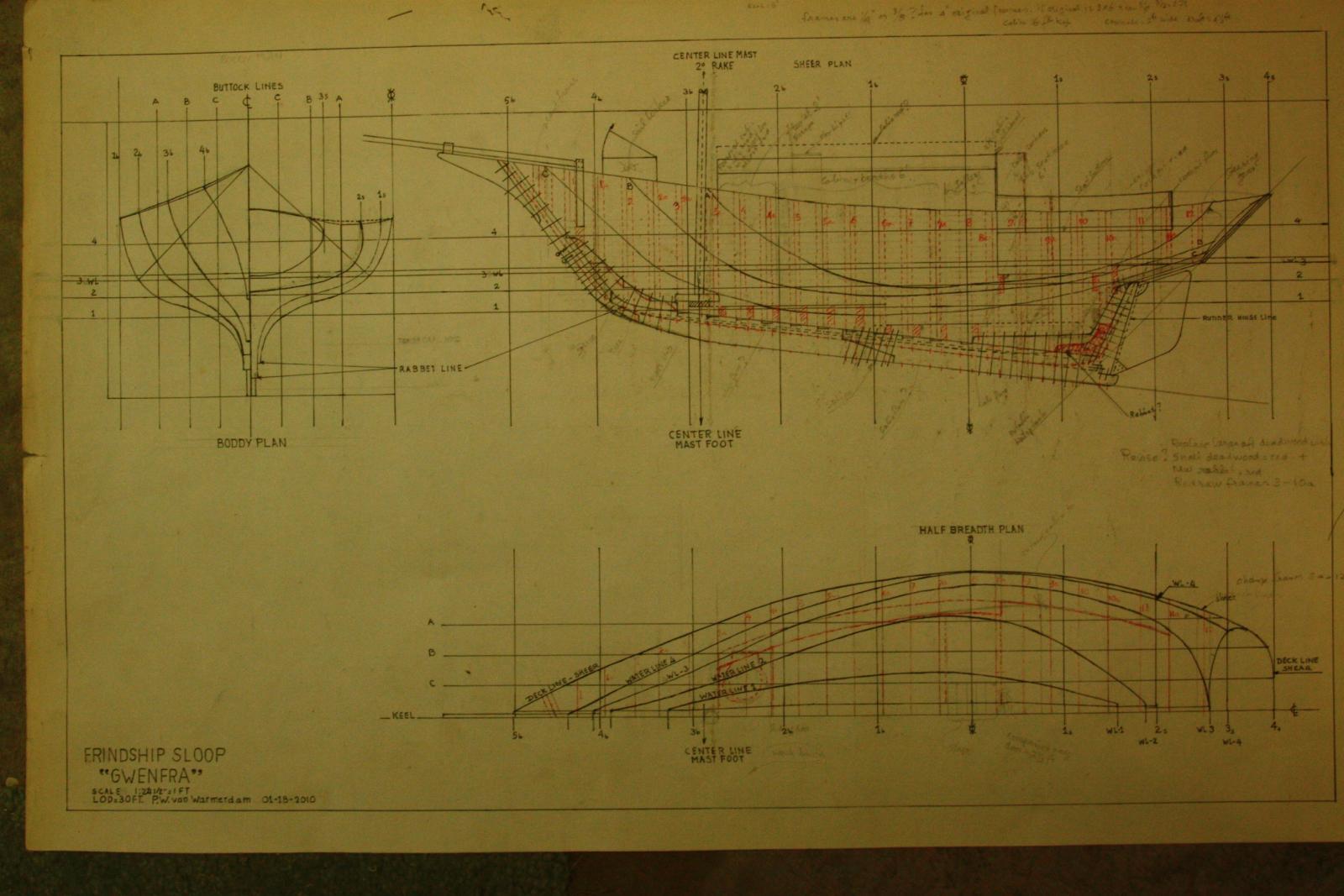
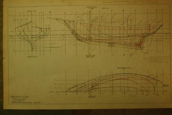
Hello all, As mentioned in my intro I made numerous sketches of the hull shape as I envisioned it in my mind and came to this final shape. As it turned out I made a few changes as I went along with the build. The lines drawing shown below shows some of the changes but I have omitted a few others. As you can see I have made several notes on it and this picture is as it appears right now taped to my garage wall. The most notable change was making the sternpost knee a little smaller. It shows red on the drawing but it wound up between the original knee and the red colored knee. Another change was the cabin and galley deck. I made it on one level. Later on in the build you’ll see that I lowered the cabin height, it just looked out of proportion but I figured that my wife and I are rather short that it would be okay. Originally it was to have been six feet headroom in the cabin. That funky looking character that looks like an O with a vertical line through the middle and wabbit ears and legs indicates the beam of the boat. I indicated the frames on the sheer and half breadth plans in dashed red for visibility and the solid red lines on half breadth plan indicate the shape of the cabin and cockpit. Well, I don’t know off hand what else to add for explanatory notes to the drawing. Each successive post will have its own story to tell. Cheers,
-
Thank you all for the likes and stopping buy this repost. @ Harvey: I have been visiting your project and am jealous Oh how I would like to get myself a Friendship Sloop, but alas I'll have to do with a model No, I wasn't aware of fss.org but I did visit their website yesterday. Very interesting. If I had known their existence and now you having drawings I could have saved myself a lot of time drawing up my own. However, It was a fun exercise seeing how my lines would come out. I am familiar with aircraft design and figured it wouldn't be too difficult. Re the sailing of these sloops, well, I don't have to worry about that now but I did sail a Navy sloop once. That's the size of a life boat and can have a crew of 16 oar's men. You must indeed have some biceps and leg muscles to handle those brutes. Way back on the back-burner may be a chance to make another model of a Friendship sloop but a little bigger and larger scale. Bob and Michael, yes, they are lovely boats and a pleasure to sail. Cheers,
-
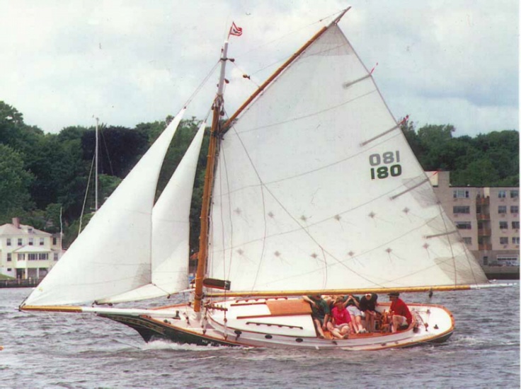
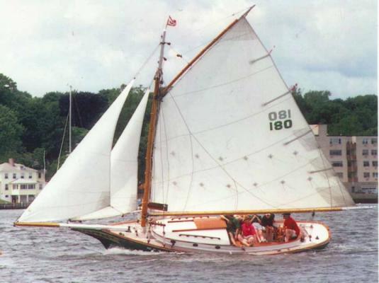
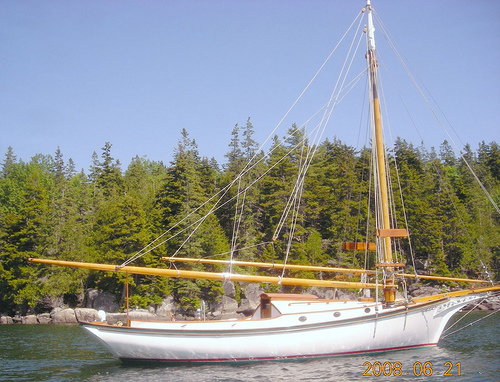
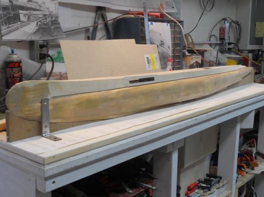
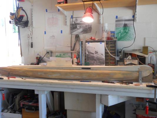
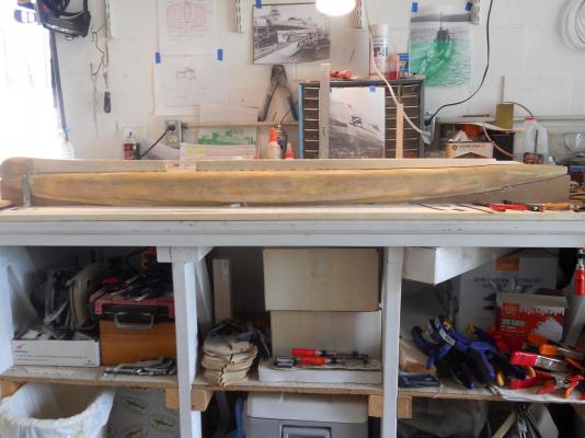
Hello everyone, This will be a reposting of my build log for the Friendship sloop “Gwenfra” that I started in January 2010 and completed April 2011. The reason for this repost is not only to add my old build log to MSW 2 but to entice those in the kit build section or “newbie’s” to try their hand at scratch building a ship model. If an aircraft mechanic, engineer and pilot type (among other trades) can scratch build a wooden model of a ship or a boat then most can. One must obviously be familiar with using woodworking tools, whether power tools or hand tools and it would also be desirable to have some of these in your workplace. First a little background history behind this particular project. When I was approaching retirement from Federal service my wife Gwen and I choose Palm Coast Florida to settle down and enjoy the warm climate over remaining in the Pittsburgh, PA area. Both of us also love sailing and have done so when living in the Netherlands after WW II and this part of Florida has great sailing opportunities. Instead of buying a sailboat (cost prohibitive, etc.) we decided to build one ourselves that suited our needs and likes. We settled in a simplified Friendship sloop, the Stevenson’s Project Del Mar 1981 “Vacationer.” With my skills and the help of an equally handy wife this would be a perfect two-year project. However, when we moved to Florida it became apparent that building a 25-foot boat was out of the question due to the lack of a suitable building place and problems with my wife’s back. So, the next best thing is to build a model of a real Friendship sloop, as they are currently sailing as pleasure craft. Another reason was to use this project as a practice piece for when I could finally build a model of a long time dream, a mid 17th century VOC ship. This doesn’t mean that I am unfamiliar with working with wood. In doing a lot of research and checking for drawings to purchase I found that I could not afford the prices asked. However, the design is quite straight forward and to a simple formula of 3:2:1. The beam is 1/3 of the LOD (length on deck), and the draft is ½ of the beam, with slight variations. The length of the single mast is usually LOD plus the draft. It also has quite a “drag” to the keel (70), which seems rather deep but it should accommodate the needed lead ballast. This is what makes these boats so seaworthy and stable sailors. The rigging is also straightforward using one mast stepped rather forward in the hull and gaff rigged with one main sail, a staysail and a jib. Some have added a main topsail and a flying jib. It usually has a square wooden bowsprit to accommodate the jibs. I knew what I wanted in the boat if I was going to build it, a comfortable cruiser for several weeks, so, I decided to draw up my own plans. I opted for 30 feet LOD with a 10 ft beam and 4.5 ft draft. This configuration could get me most everywhere on the St. John’s River, the Intercoastal Waterway and even venture out on the Atlantic ocean. In general terms she was going to have four bunks, a full galley, a dry chem. toilet and washroom. She was going to be fully electric with a 5 HP diesel powered generator to supply 24 volts DC and 110 volts AC. She was not going to have a build-in engine to drive a propeller for calm wind conditions or docking. Instead I would use an electric outboard motor. The electric loadbank would be 2 heavy-duty truck batteries to supply 24-volt DC power and 110 volt AC. The diesel and generator assembly would be located in the forward sail locker in a stainless steel enclosure with a fire detection and extinguishing system as is used on aircraft auxiliary power units (APU). The batteries would also be in the sail locker. The keel would be made in three pieces, tapering in thickness from the widest frame forward and aft. It would have deadwood knees holding the sternpost and cutwater to the keel. The frames would be 4 X 8 inches and the planking 1½ X 4 and 1½ X 6 inches as required. I’ll leave out details of the masting, rigging and the various systems. The wood for the boat would be yellow cedar from Georgia except for the planking, which would be oak and birch for the deck. The model Among the many very handsome boats I found on the Internet I used “Banshee” and an unnamed sloop as examples to emulate (pics below). The scale of the model is 1:25 and I have used poplar throughout. I used ¼ inch poplar sheet stock, a rather soft wood. If I would do it again I’d use a better quality hard wood. The keel is ¼ inch wide and tapered towards the bow stern. All frames are ¼ X 3/8 inch and close to room and space, there are 24 frames overall not counting the counter. The three keel pieces are scarfed, glued and pinned with bamboo pins as are most frames. For de deck, cabin roof, hatch covers, interior bulkheads and finishing I made my own plywood from cherry veneer to 1/16 inch thickness. I could have bought 2 mm plywood at Hobby Lobby but I wanted to see if I could make my own plywood. I even managed to make some of the interior plywood 1 mm thick. There is no part on this build that is “store bought,” everything is made from stock material, including the hardware. Well, okay, I bought the rope for the rigging from Model Expo. I sure hope you enjoy this build and find the encouragement to try your hand at a scratch build yourself. This is Banshee, a very handsome little sloop. You'll see similarities with my model when it;s completed. Another very nice looking sloop. I made my cockpit a little smaller to allow more cabin space for four bunks. Cheers,
-
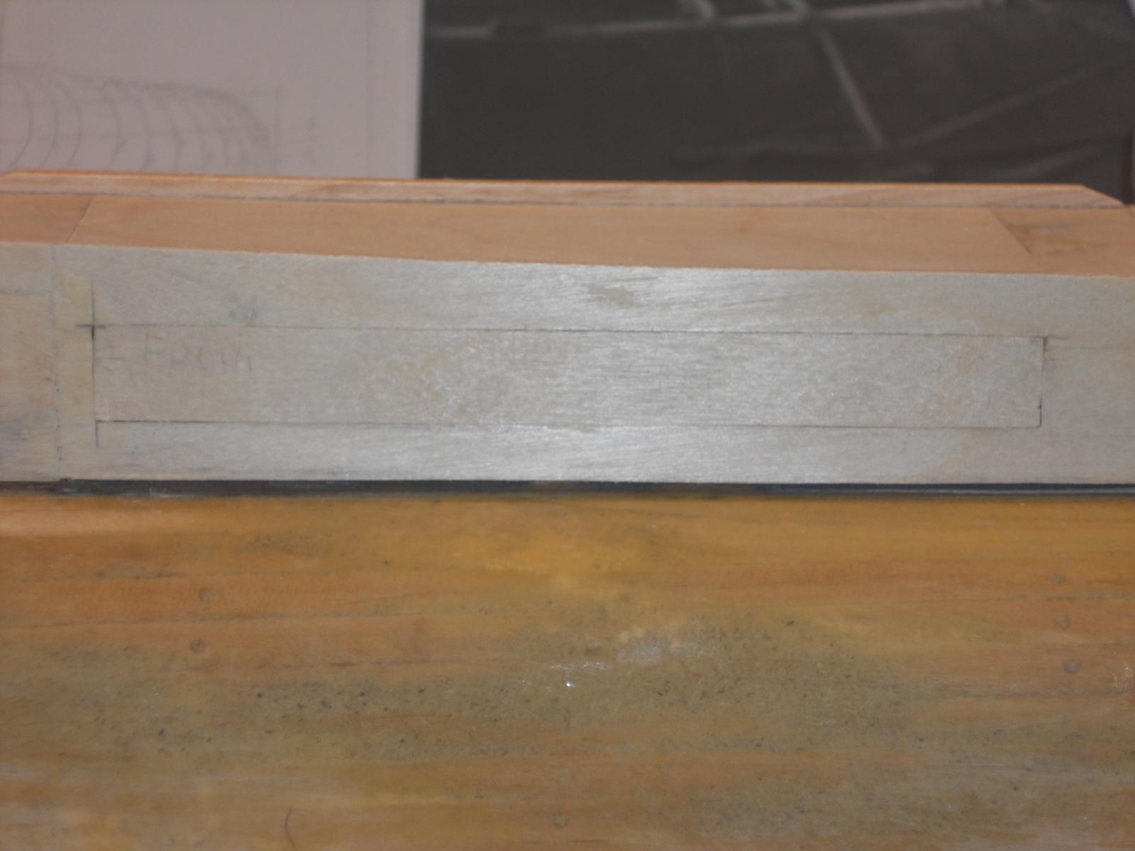
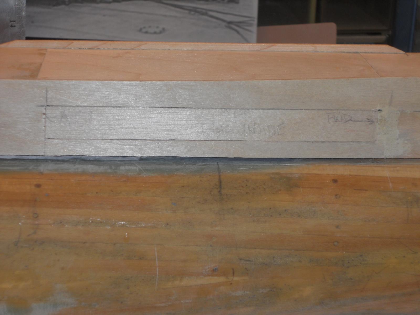
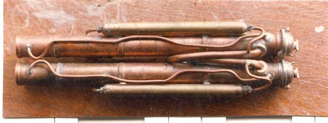
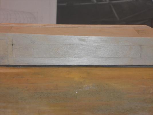
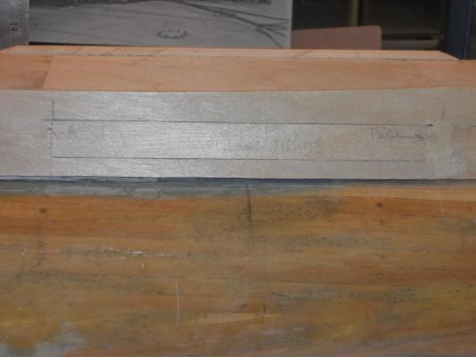
Hey Kevin, thanks for dropping in. Yes, we are moving along at a steady rate, oh I'd say about 9 knots. Sometimes though we have to stop and reverse to correct a problem but things are moving ahead again Hoi Popeye, yes, it appears that the modeler in Holland made it all out of copper tubes and rods. There is another Dutch modeler who made a large RC model of the K XVIII Dutch sub and he managed to fire dummy torps too! btw, my dad also served on the K XVIII before his tropical tour ended in 1938. Well, even with my band saw being out of commission I managed to find some other things to do on the O 19. I made the outside doors for the deck torpedo area. It's a start, I now need to reinforce the insides to achieve the proper shape and figure the hinges and where they go. At least it'll keep me busy. I also installed the bow trim plane center pivots. It's just a wooden dowel and it'll have a brass pin as the pivot shaft going through it. Here are a few pics of the doors. This is the door panel that closes the opening which is in this model the outer panel. I'll have a slightly larger inner panel glued to it on the back side that fits against the inside of the deck side plates. This inner plate makes the door stiffer and acts as a stop and assures a proper fit of the door, I hope. I still have to add a few stiffeners on the inside. Cheers,
-
Hey, I'm joining in too! Great idea and it holds special interest for me. For many years now I wanted to make a painting of the wreck of the ship my father was killed on, Hr. Ms. Java. She went down due to a Japanese torpedo hit during the battle of the Java Sea, Feb. 27, 1942. She lays 70 meters down on the sea floor, it's dark and murky. So, one of these days - - - - Cheers,
-
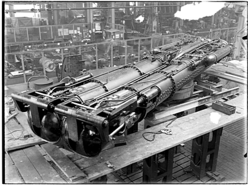
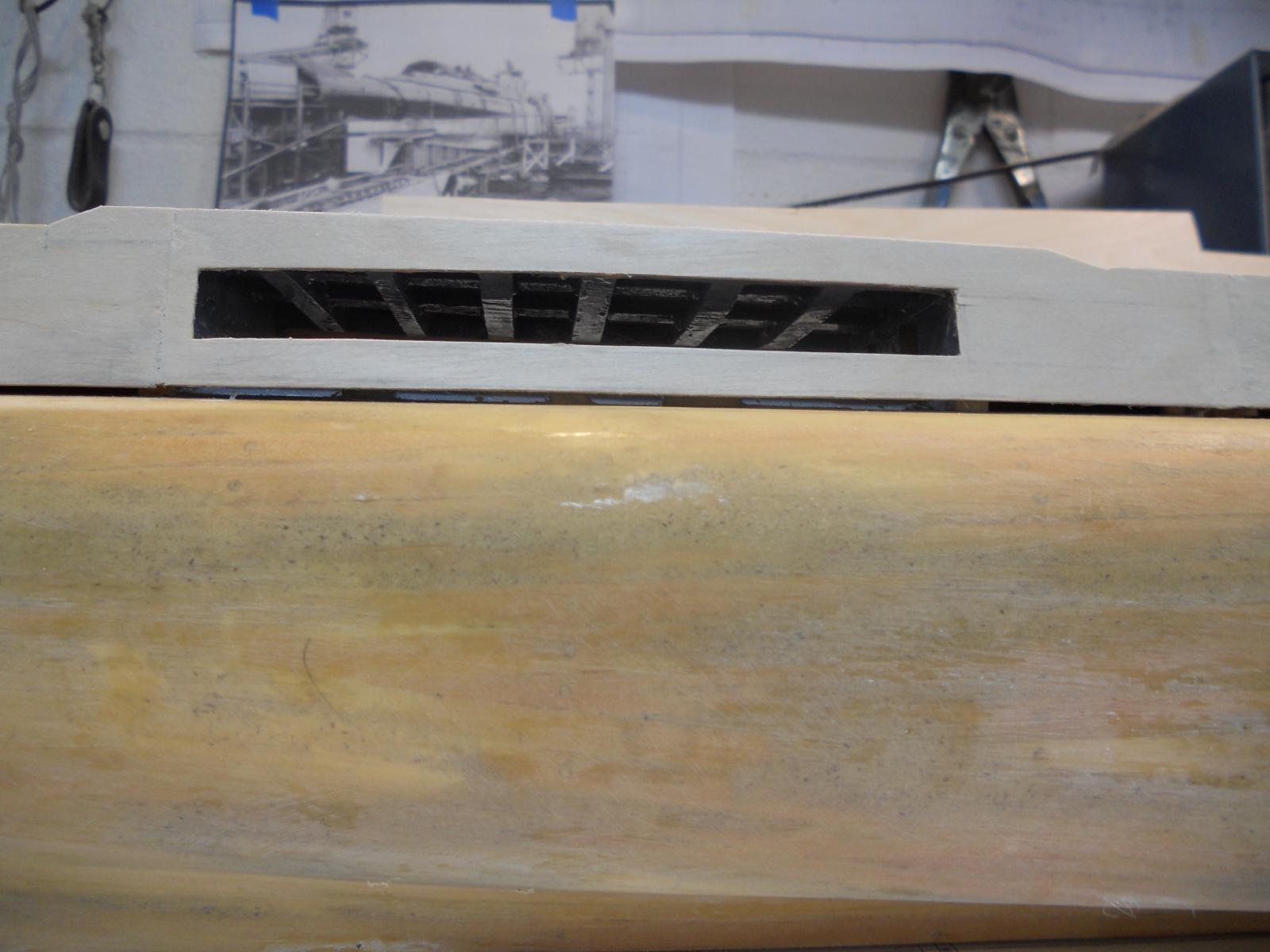
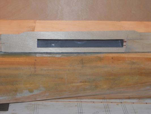
Thanks to all for your "like" indications, it means a lot to me and, thanks to Mark, Anthony, Paul and Ian for visiting my shipyard! @ Paul: Originally I had not planned on making a model of the deck torp launcher and showing it in situ and making rotatable. However, as with my VOC ship, things have a habit of getting out of hand So, a month or so ago I thought 'why not.' I have a few pics of the launcher as was build by Wilton Feyenoord and just recently also a pic of a model from a fellow builder in the Netherlands. So, the answer is yes, I'll make a model of the launcher assembly and place it on its rotation place. I also need to make the two doors so they can operate. That way I can open the doors and rotate the launcher into firing position. Weathering the boat with everything on it was not the plan - - - - right now. I wanted to show the model as my father knew it brand new when he was assigned to be the quality control and safety officer back in 1938. That means very little weathering and nicks and scrapes. I'm then also bound to put the teak deck strips on, which is a hellacious job at this scale, 1 mm strips! Torpedoes? Yes, I'll be making a few of them as well. @ Ian: To tell the truth I also don't know much about submarines. My whole life has been in aviation on the technical side of it as well as flying them. But I'm learning as I go along and I have a good teacher in Gino. It doesn't mean that I'm totally devoid of any understanding of how they are build from an engineering point of view. In general terms I do know but not the details. There is not much difference in the design philosophy between aircraft and subs, This afternoon when I wanted to use my bandsaw to work on the rudder mount the drive belt broke I immediately ordered a new one but it won't be in till the eighth I'll have to find some other projects to do and work some more on the VOC ship. It's either that or laboriously work with hand tools like chisels and sand paper. I need to taper 3 pieces of 1/4 inch wood of 3 inches square. Hmmm, maybe not, too much like work and a chance to cut myself. Okay, so minor setbacks are to be expected I guess, not the end of the world. Below a few pics of the deck torpedo launcher. This is a picture from a model of the deck torp launcher made by a Dutch modeler. This is a photo made by the boat builder Wilton Feyenoord of the deck launch tubes. Cheers


-
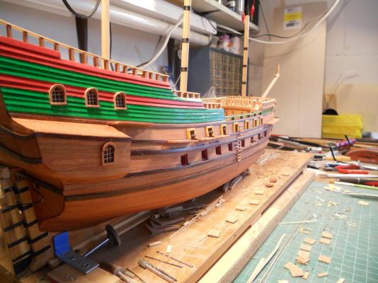
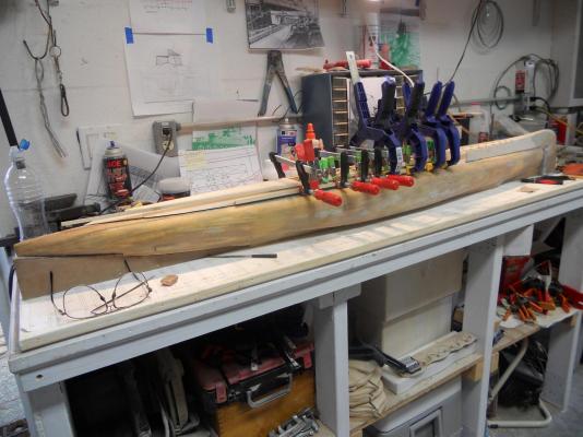
Today I had some time between paint drying and glue curing on the O 19 sub project that I finished the top gun port mouldings. They are now CA'd to the hull and look quite nice. I'll have to force myself away from the O 19 build so once in a while to work the lower gun port lids. Here are a few pics of how she looks as of this afternoon. Cheers,

-
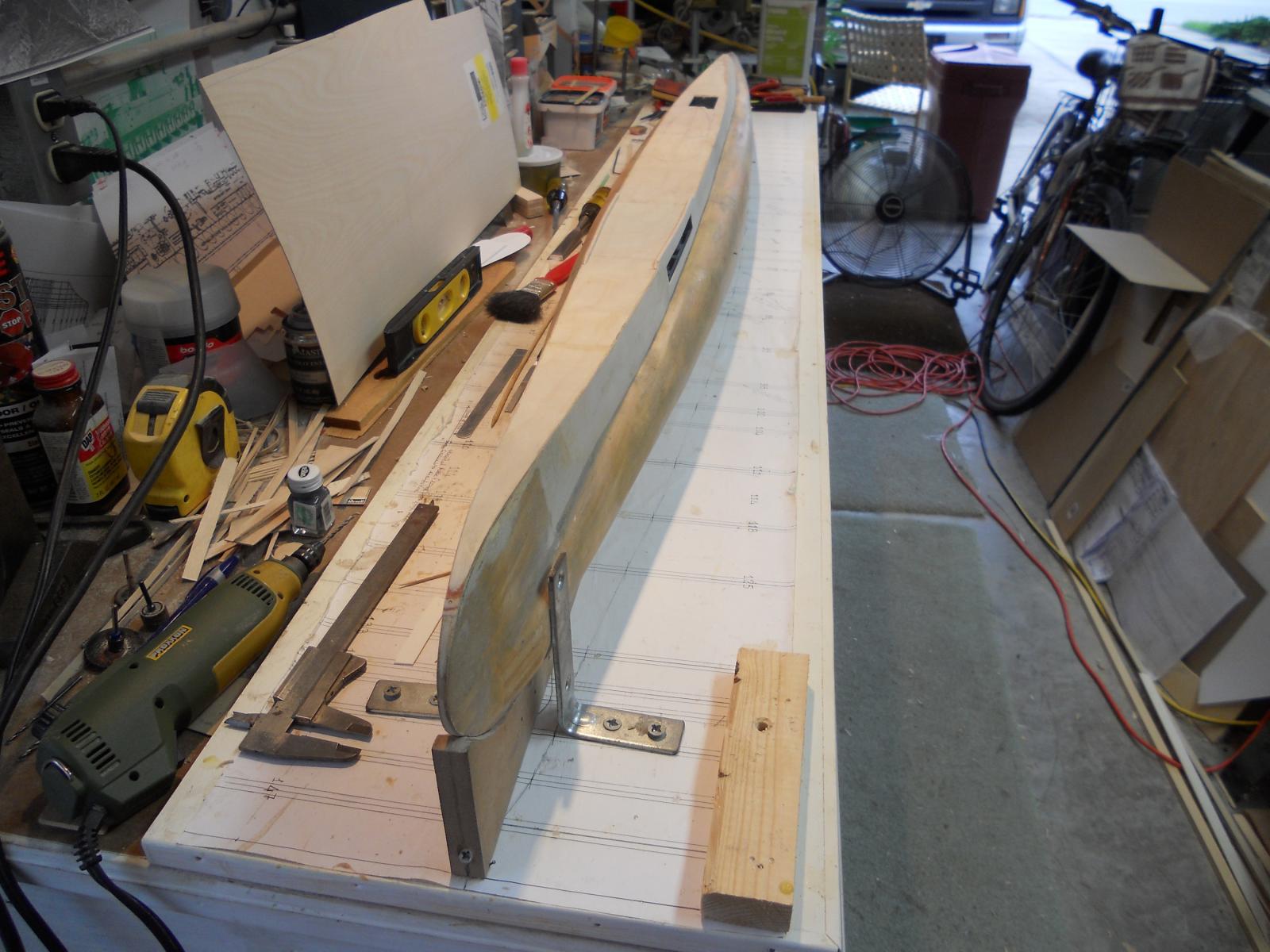
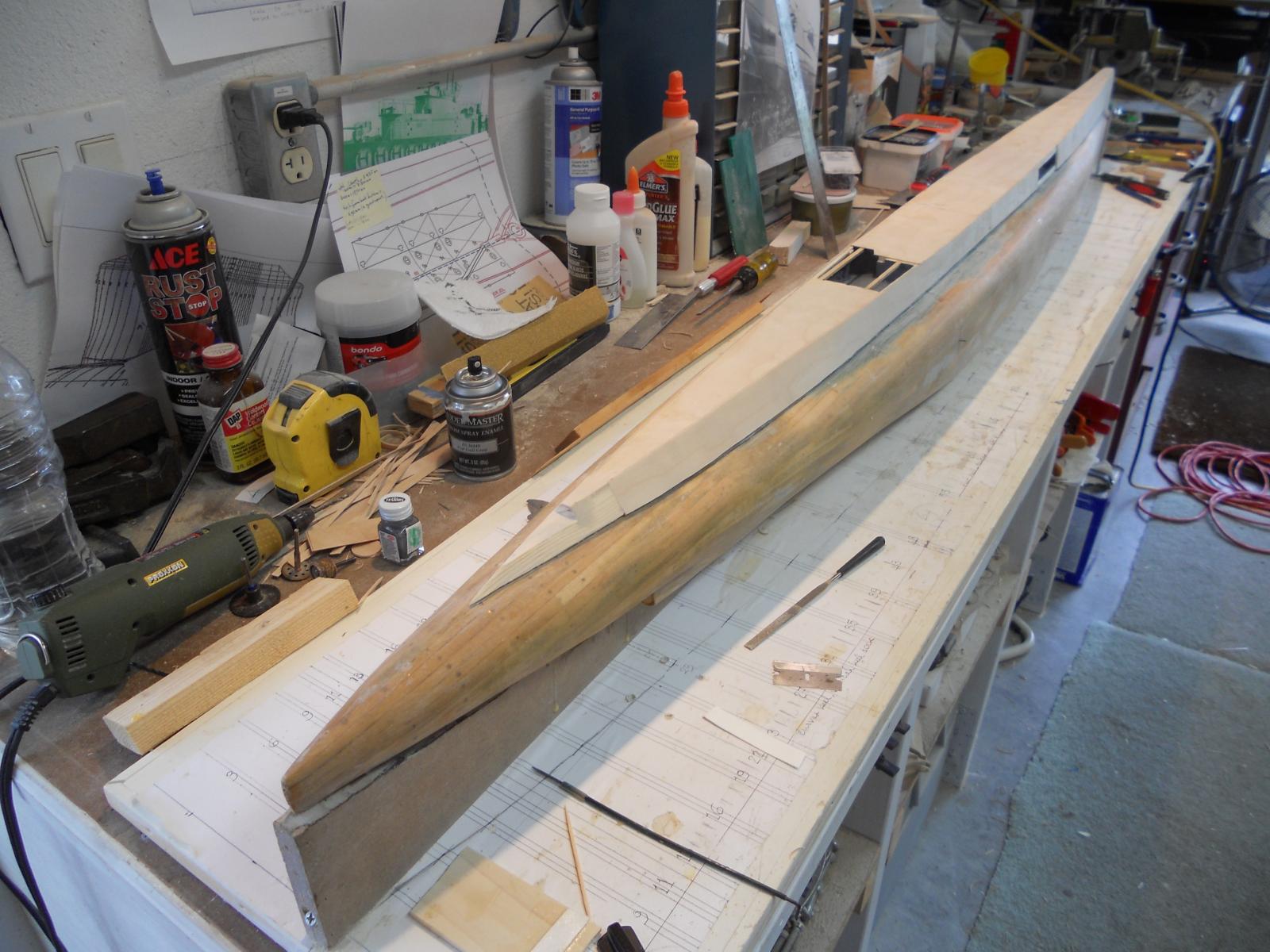
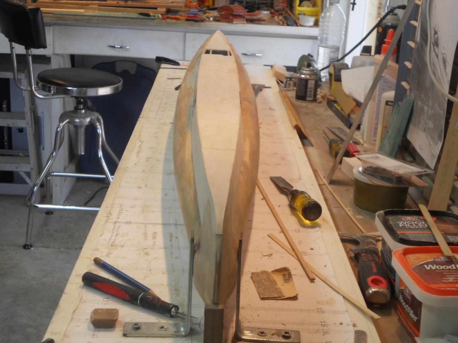
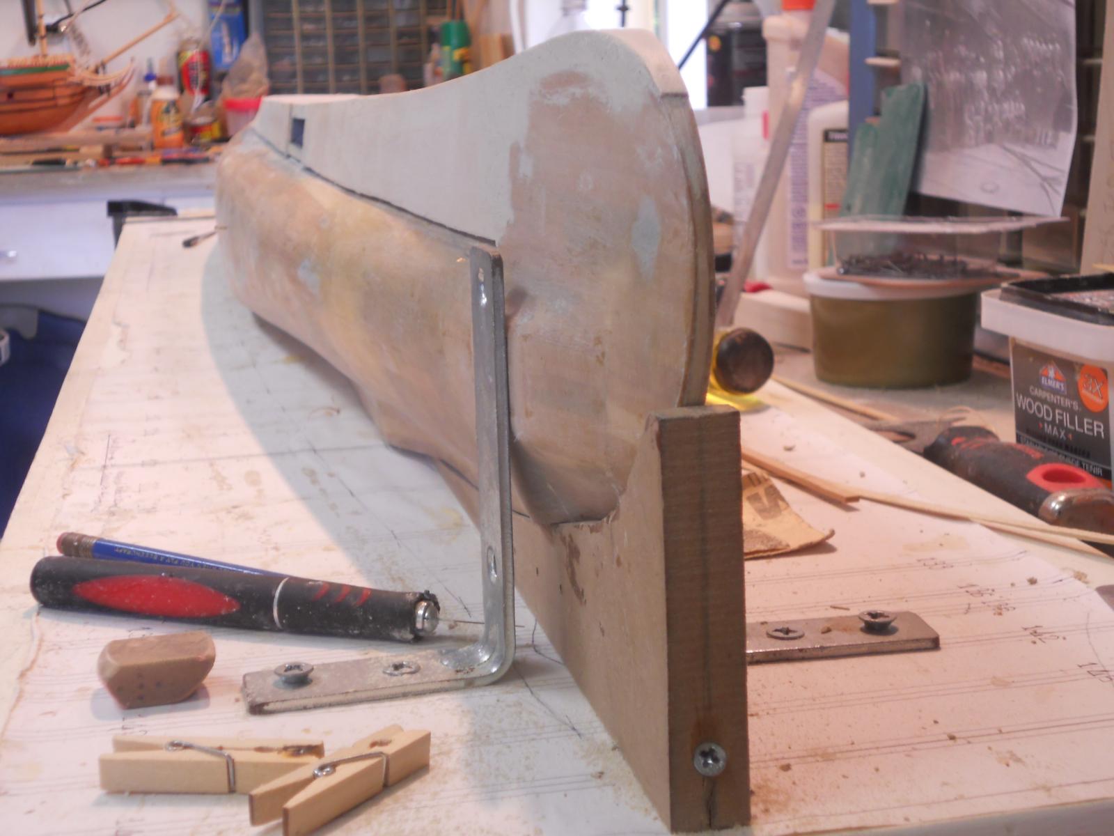
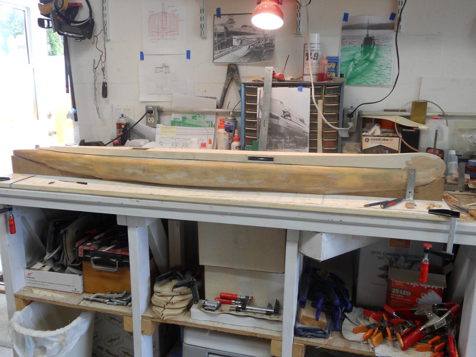
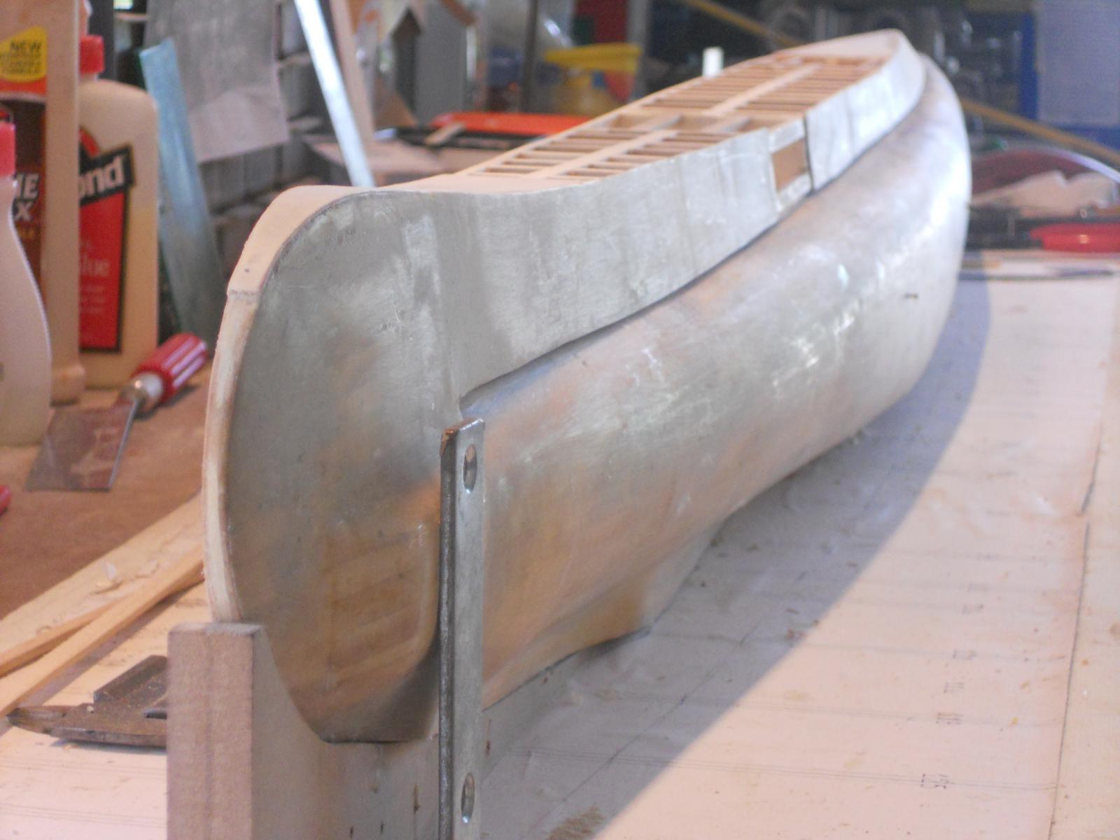
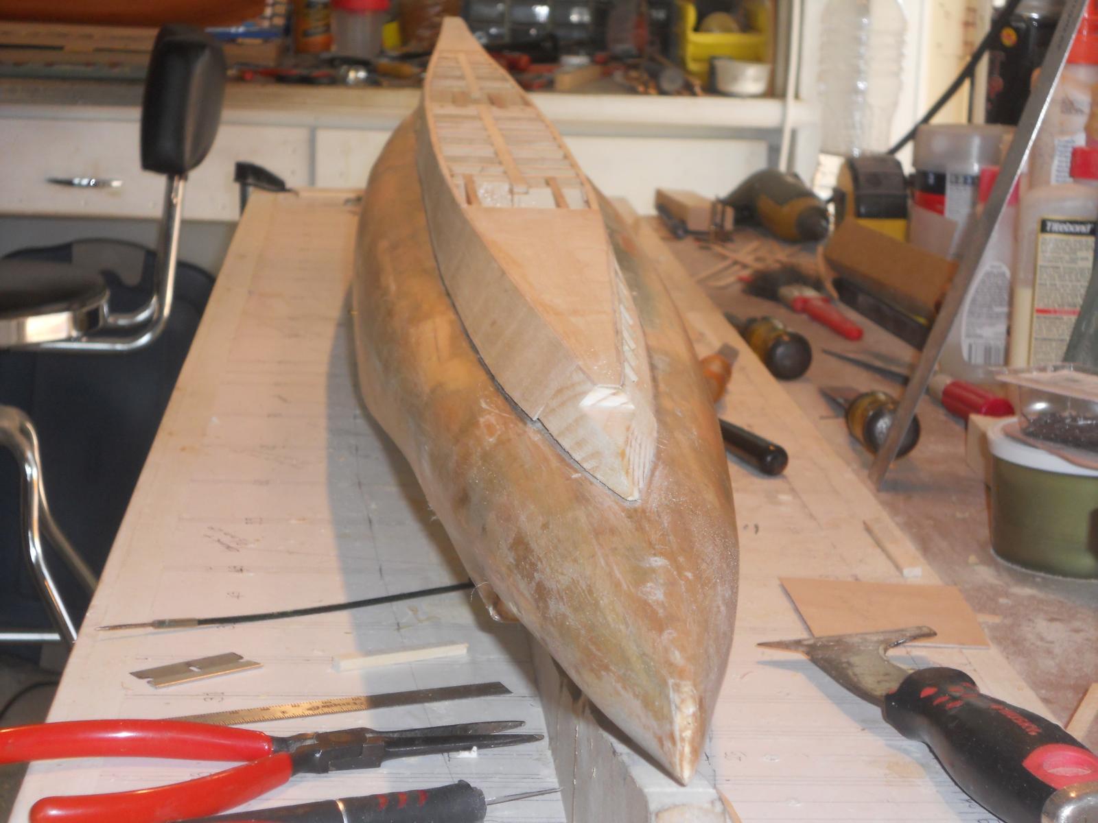
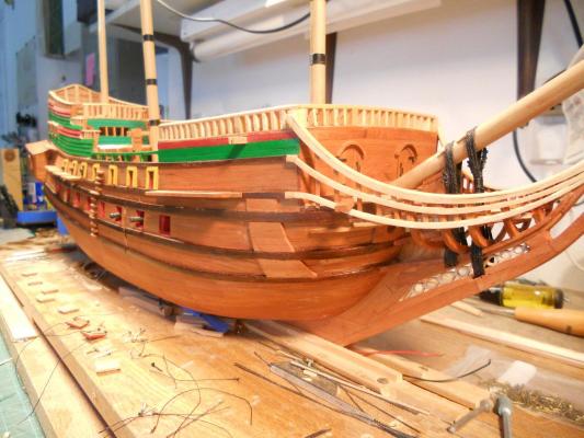
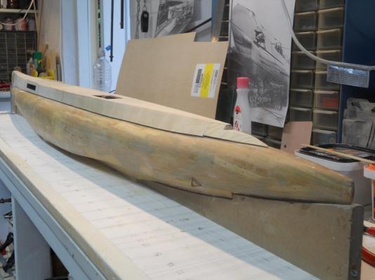
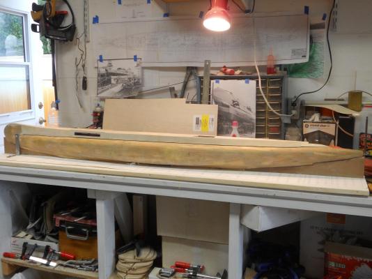
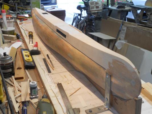
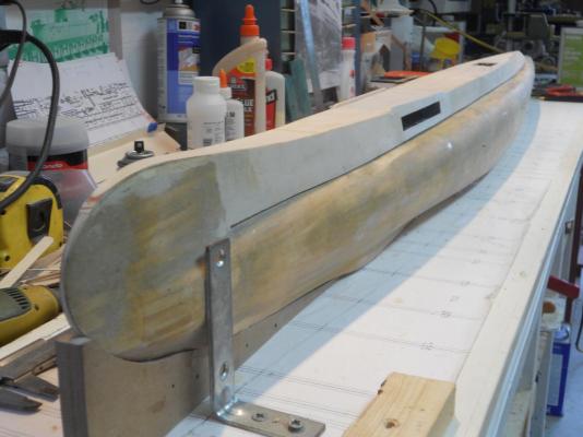
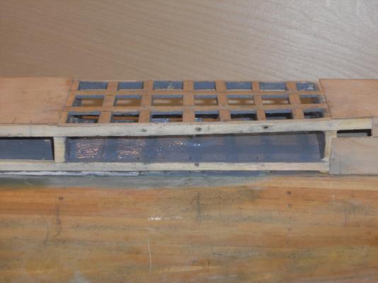
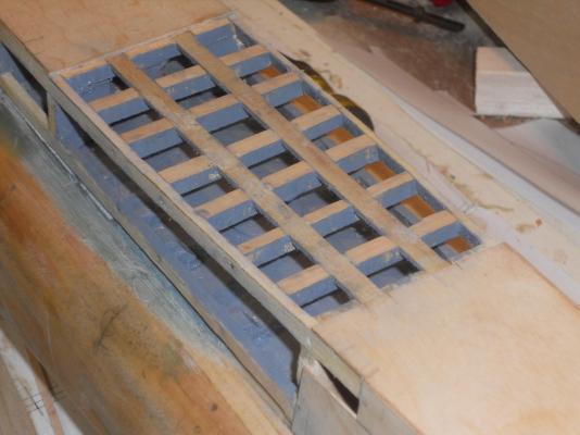
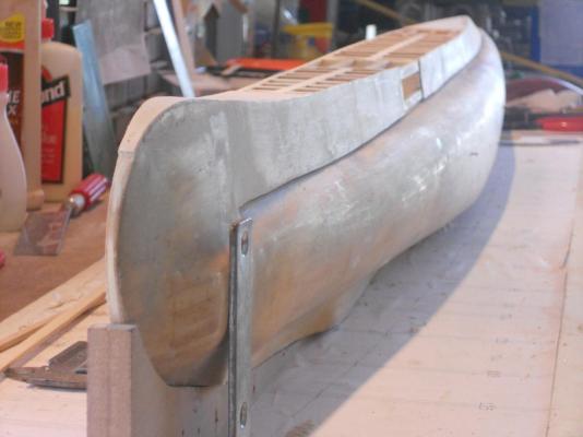
Thank all of you for the many likes for both the VOC ship "Surabaya" and the O 19, really appreciate it. The rework for the deck torpedo tubes is now completed except for some final trimming and I'm quite satisfied with the result. I'll wait with making the torp launcher and the doors till later. I really want to move on to the stern area and start with the props, rudder and diving planes. I'll simulate the stern torpedo doors with paper. So then, for today's post I like to show all yuns how she looks as of this late afternoon. This is a cloe-up of the completed rework on the port side. I angled the camera up a bit so you can see the deck beams. There is still a little trimming left to do but I was anxious to take a few pics This is a 3/4 bow side view. You can just see through the torp compartment. I had to take a stern view forward. This is a full profile shot. It really shows the lines now, nice and sleek A bow view from slightly above on the port side. Starboard bow view from slightly above. It shows the deck pretty good with the raised side plates. The admiral likes this bow shot and so do I Cheers,


-
Hi Gino, Correctomundo my friend. I am quite well aware of the length of the torp tubes. If I want to show one door closed then that also means that the launcher will not be swiveled out I was contemplating of making the doors operable so I can demonstrate the rotation for launch position that's why I made the pivot point. Perhaps too ambitious? The doors hinge at the bottom and lay flat on the top of the pressure hull. There is a longitudinal beam on the bottom where the side panel is fastened to. The hinges can be mounted to them. It's getting more elaborate as I'm progressing with the build. And yes, with the scale at 1:50 then we have to divide that number with 50. According to the drawings you gave me and the ones I purchased through Remco the center of the launcher is at hull frame 98. The "christmas tree" is also at that location at the center of the crew compartment. @ Popeye: Thank you for keeping track of my progress and foibles The entire rework is now completed and I can go on with the below waterline external stuff at the stern. NOTE: this post was edited by adding a picture Gino posted on page 15 - post #225. Due to the disappearing of many photos, including Gino's, Ia m now adding this photo here. Cheers,
-
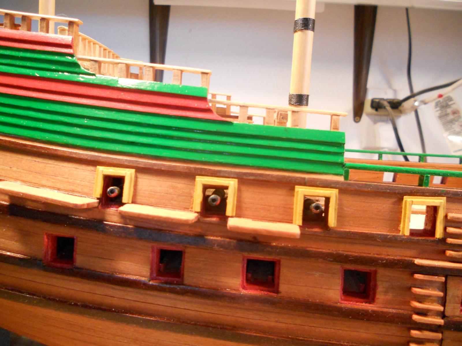
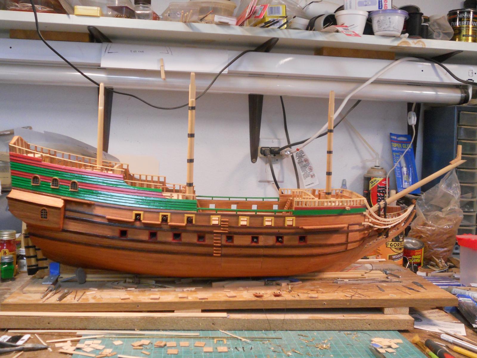
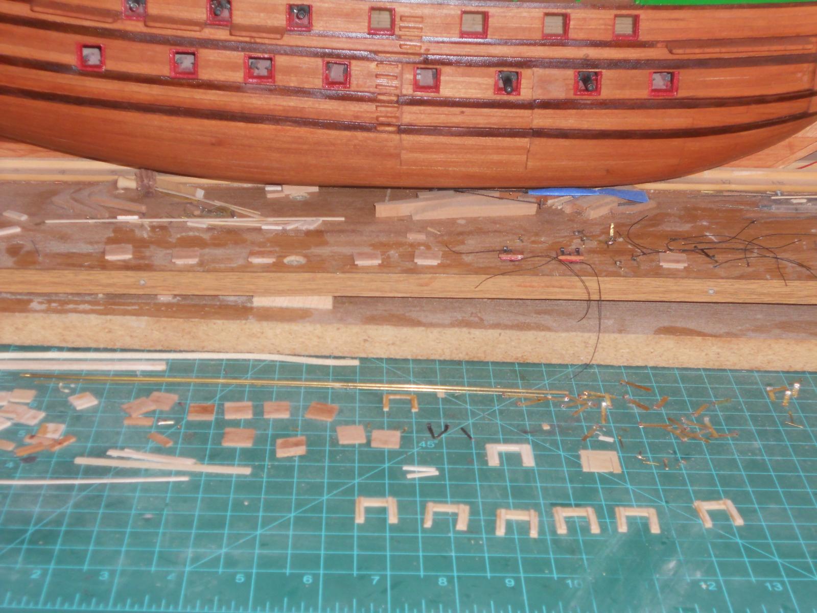
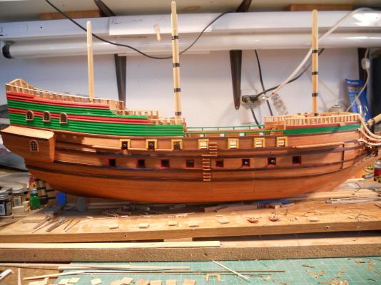
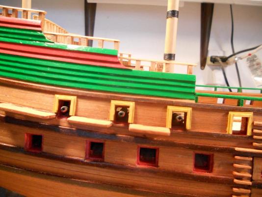
Hello everyone, After a few weeks of working hard on the O 19 sub I had some time to devote on the VOC ship "Surabaya." I rotated the build board so I could work on the starboard side. Today I completed the base of the lower gunport doors. They are now ready to be painted red on the inside and get the hinges and open - close ropes installed with their hardware. I had made the rough hinges already a few weeks ago but they need final trimming. On the pic below you can see them all ready and waiting. I also managed to start with the top gun port mouldings, just a little more work and they are ready to be painted and glued on. You'd think that I have nothing else to do but that's not the case There is still a lot of yard work to do and then my fish pond. Wow, my closeup lens is distorting the ship quite a bit. Okay, the gunport lids I completed today are laid out in front on top of the build dock. The upper gunport mouldings are laid out in the foreground on the mat and the rough hinges are in the mat and on the build board. Getting close now ! Cheers,

-
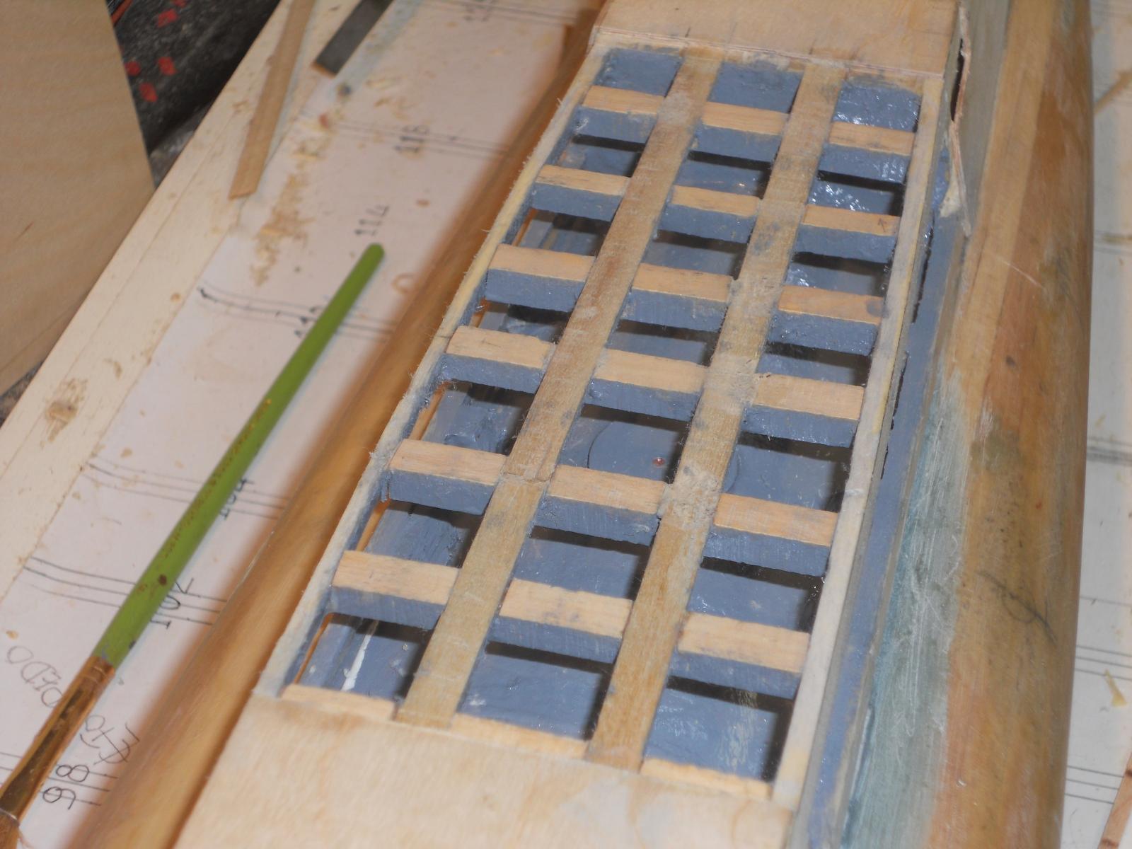
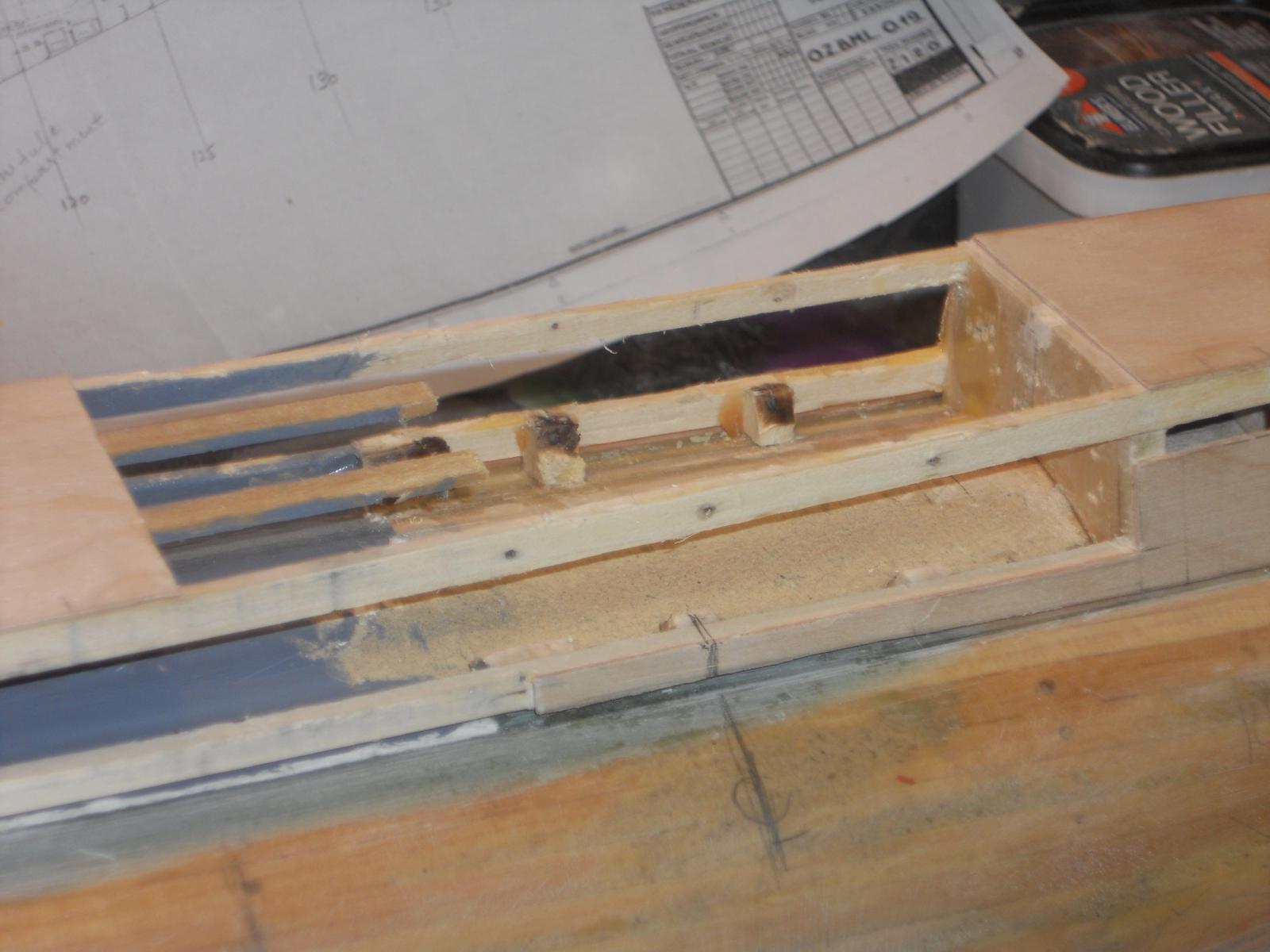
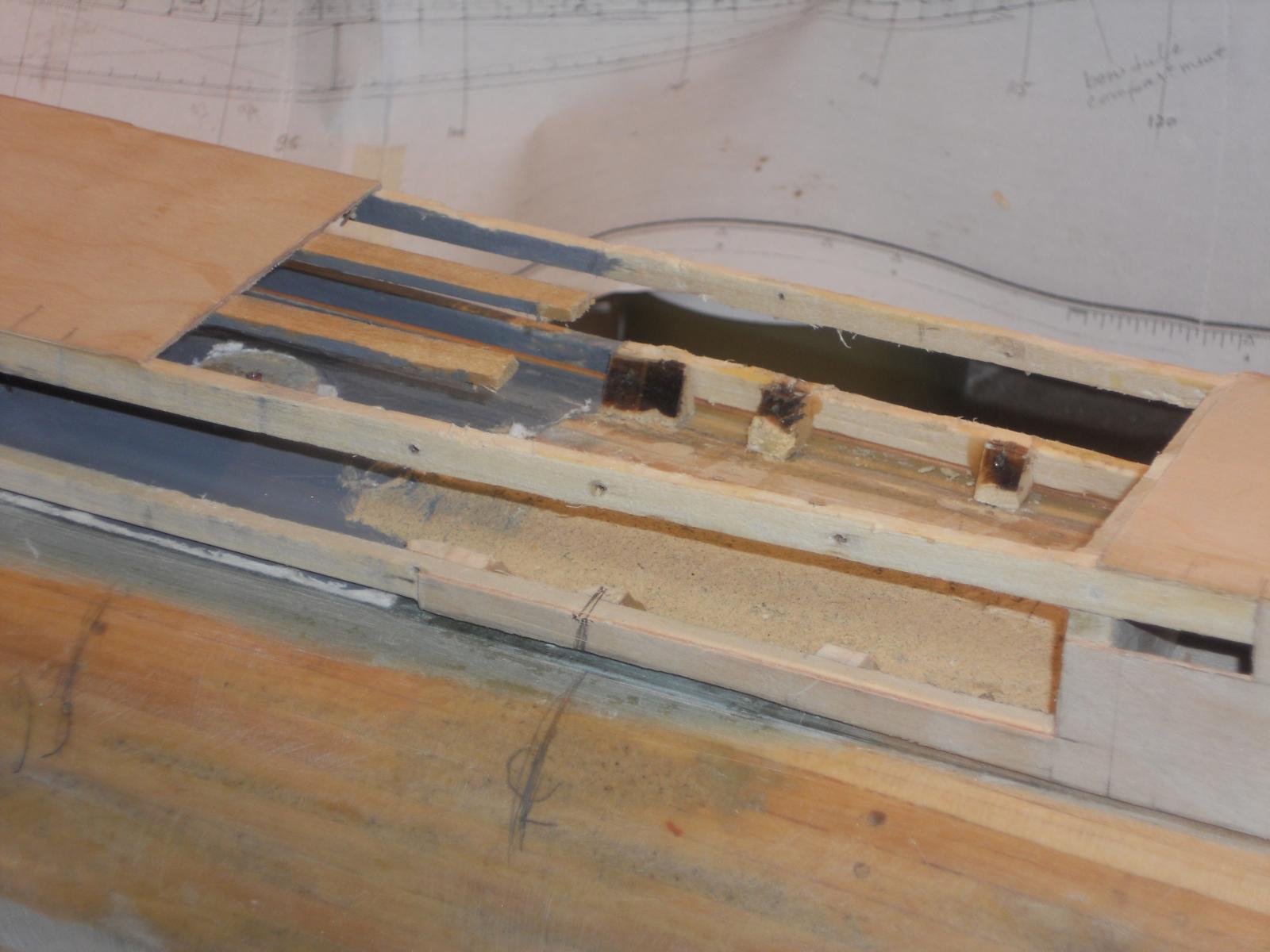
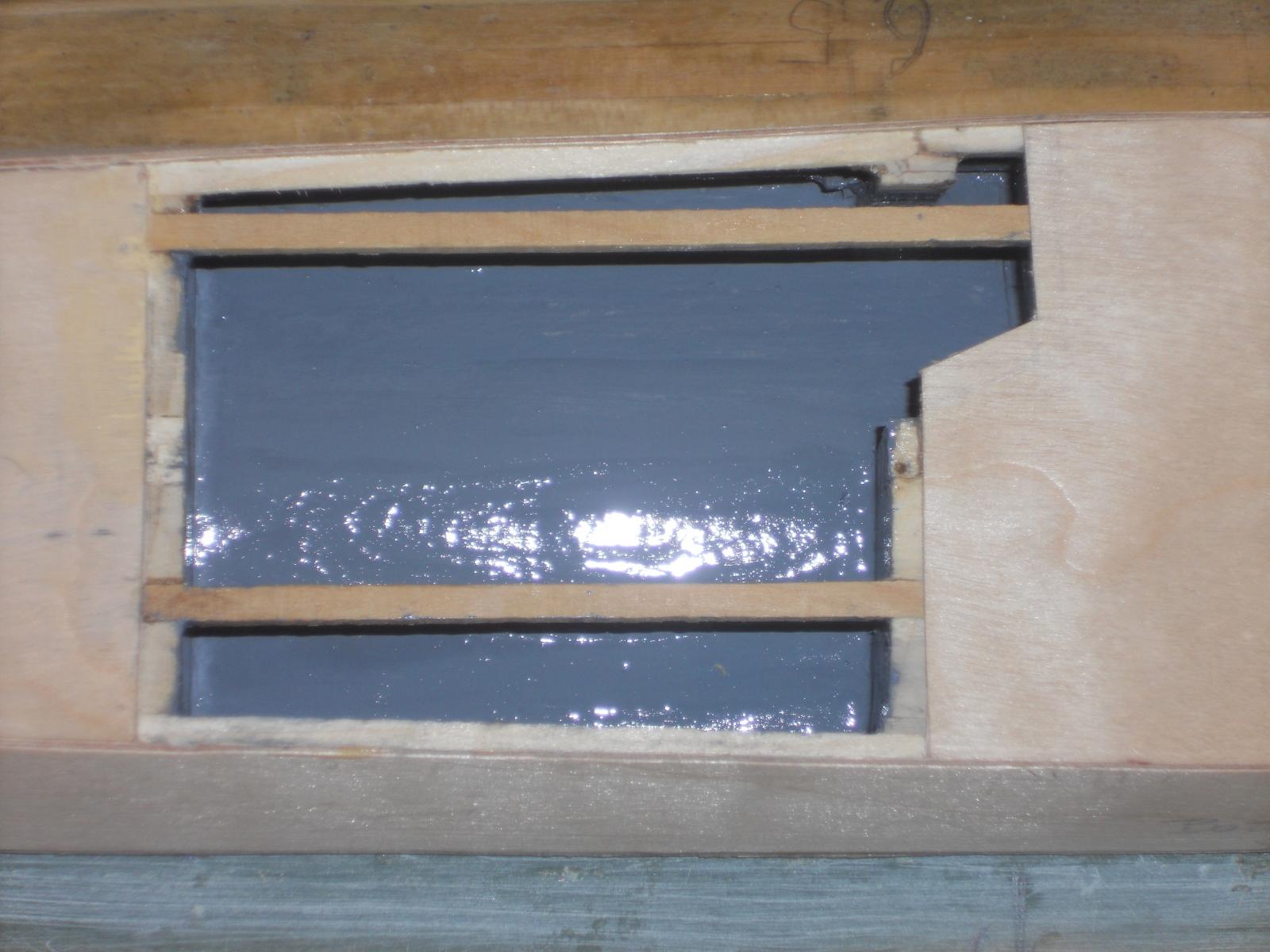
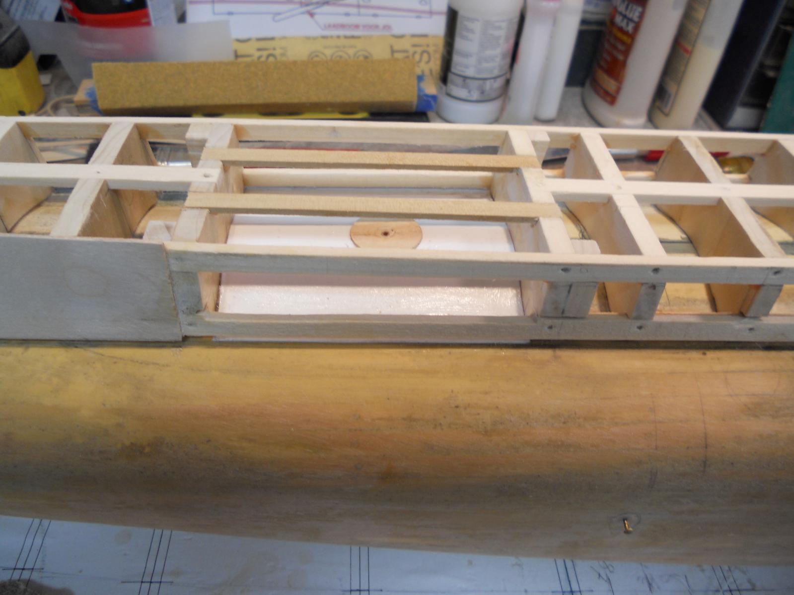
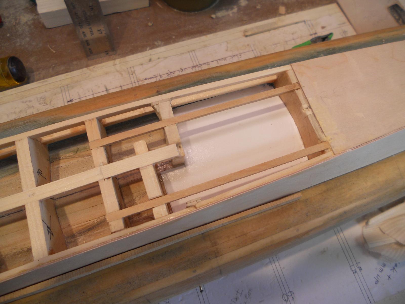
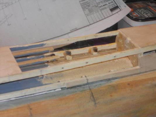
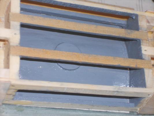
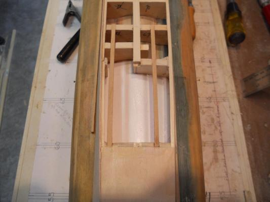
Thanks fellows for your words of encouragement and sympathy. Yup, stuff happens but it usually does to "the other follow" I'm still trying to figure out how I miscalculated the location, other the blaming dyslexia Well, yesterday and today I was very busy making up new parts and cementing them in. I made a completely new deck framing from boxwood and I bought a new sheet of 1 mm ply at the local hobby store for the deck and side panels. I now have enough for the con as well. I got as far as painting the inside of the deck torpedo compartment and glueing the deck plate on. I also made the starboard side panel with the cut-out and fitted it. It's also ready to be glued on. Wow, I've been busy and even had some time to work on the VOC ship between glue curing times. Below are a few pics of the progress so far. deck frame beams installed and the compartment has one coat of gray paint. I did not put nails in yet, that'll come tomorrow before the side panels are installed. I want to paint the underside of the new deck and deck beams first. One never knows if people want to take a peek inside This is looking towards the bow and you can see the torpedo assembly swivel plate with the copper tube to enable the assembly to rotate. I'll also try to make the side doors but may keep one side open and the other side closed. This is looking towards the stern and you can see that it's in need of a second coat of paint. The starboard side panel is cut and fitted, ready to be glued on after the bottom the deck plate is painted. Yeah, the are a few small pieces of ply chipped out but it'll be filled in and eventually covered with paper. You can also see that the deck panel is glued on. Here is the starboard side panel loosely attached. It's a nice close fit. Cheers

-
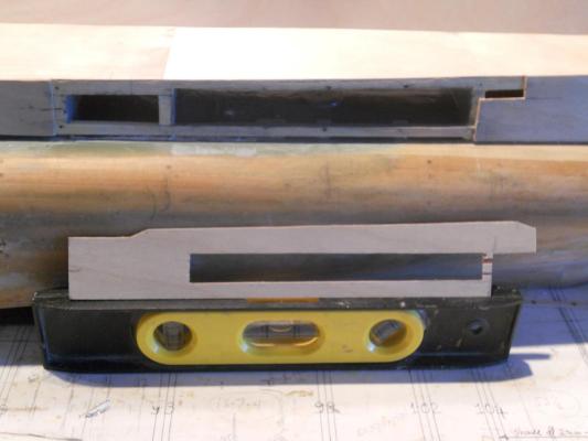
Well, Piet goofed with the location of the deck torpedo location Yup, I'm sorry to say that I have to dismantle a small section of the forward deck structure to correct the error. I have to move it forward some and make it larger. I don't know how I could have done such a dumb thing but okay, no big problem, just a little more time spend on it, that's all. After it's all done it wont even be noticeable. I'm glad I caught it now rather then later when it would be more of a problem. I need to get a sheet of 1 mm ply anyhow for the con, so I'll have plenty of wood. I'm using boxwood for the new deck beams with a few extra for additional sturdiness for the deck plate. Even without the three frames I removed the structure is still rather stiff and that's a relief. starboard view of the removed side and deck plates and the three frames. The cross beams will be made from boxwood with two beams length wise. The center of the torpedo launcher just happens to be in the center of pressure hull frame 98, which will give me a solid footing for the rotating tube. Cheers,
-
Thank you all for the likes, appreciate your votes of confidence and appreciation for the boat. @ Popeye: Well, that were the first words out my admiral's mouth, 'where are you going to put it'? Fortunately the model is narrow and not tall. I'll make a shelf across one of the windows in my studio and place her there. No problem @ Ian: Yeah, I was thinking how the sub would look like with three masts, square rigged and a growling lion on the bow as a figure head - - - - - hmmmm - - - - - well - - - - nah, I guess not @ Borus: Good to hear from you Borus. Right now I'm thinking of making only one mine location semi workable with the top lid open so we can see the tube with possibly a mine in it. As far as the bottom doors are concerned, they'll be simulated from paper glued to the hull. It would be nice to make all twenty workable but I need to really get this thing completed and all the other external "stuff" is going to take a lot of time. At least that's what I want to make look as close to the way my father knew the boat. The bottom mine compartment doors are not a priority. Cheers,
-
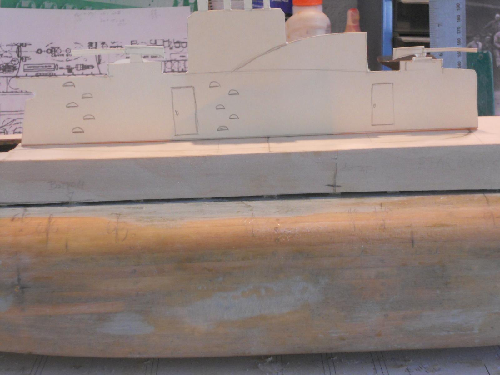
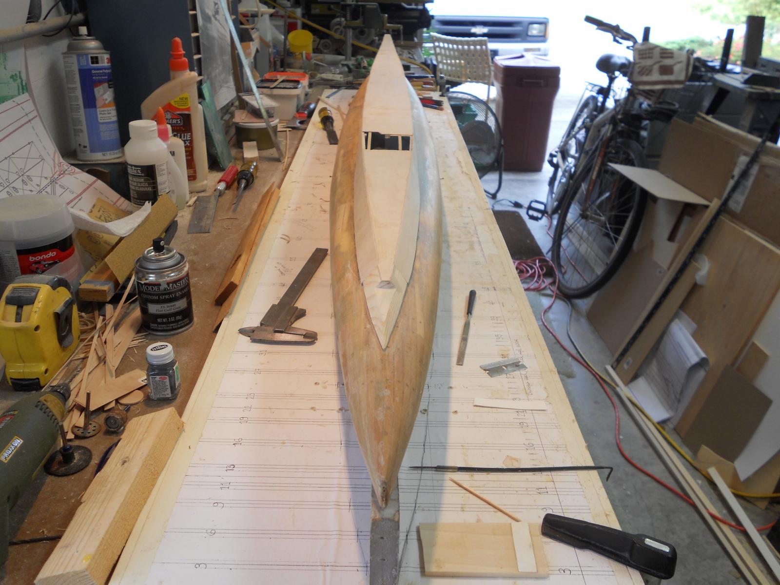
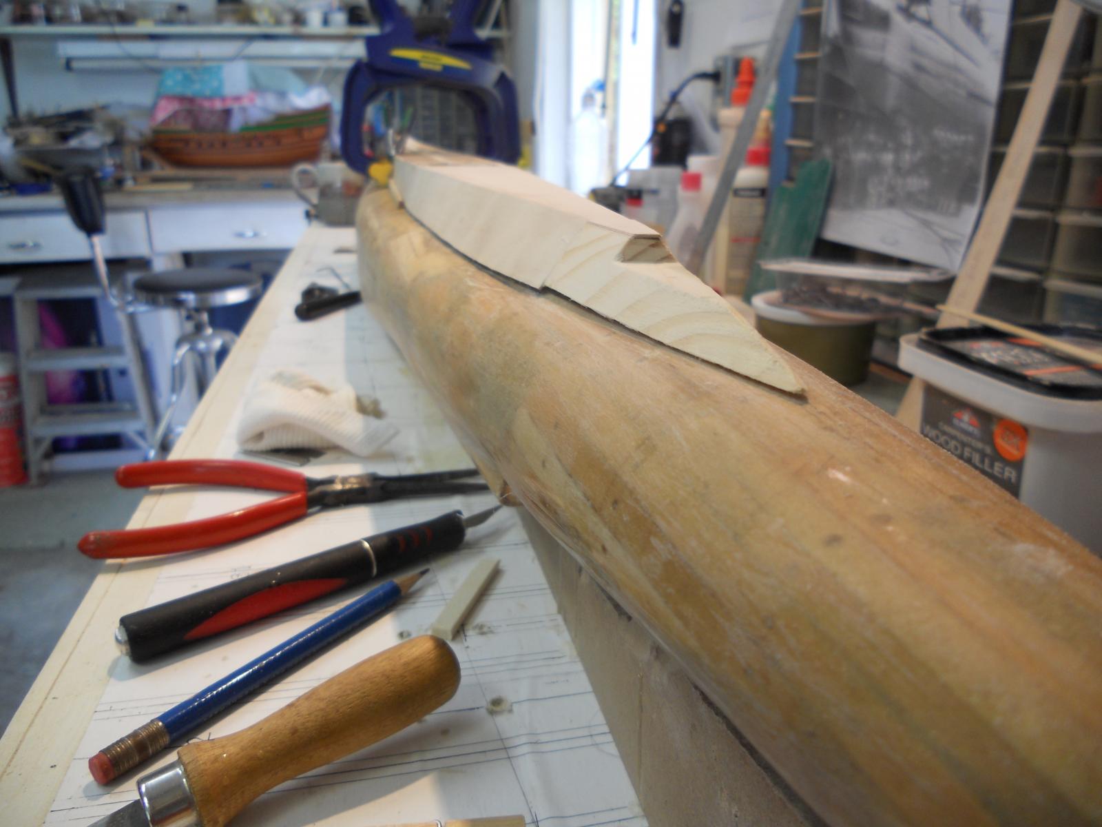
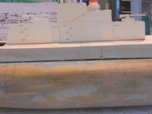
Hey Ian, looking at plans is good but your poor Unicorn is calling you, I can hear it from here, "finish me, finish me." Popeye, the con will be build separate and then attached to the hull, at least that's the plan for now, may change my mind. I need to do the below the water line stuff first and the bow dive planes. The con may get in the way having the boat upside down for some of the work. Just for the hellibut I quickly made a facsimile of a conning tower and taped to to the hull. It's not nearly the way the O 19 con looks like though. A full profile pic with the fake con taped to the hull. It kinda disappears in front of all the background clutter but good enough for a joke. Cheers,
-
First of all my thanks to all who send me likes. Ian and Popeye thanks for dropping in and your kind and encouraging words. Ian and Popeye, the doc's visit went extremely well. After I woke up from the "sleepy juice" they shot into my vanes the doc said that everything looks very good, much better then 3 months ago. It appears that my old bod's immune and self healing system is working in hight gear repairing the damage from my cancer radiation treatment. Popeye, I indeed came home with the right stuff in more ways then one After checking my for bod for any missing parts it checked out fine Then after lunch at the Olive Garden, one of the admiral's favorite places next to Outback, we set course to the Hobby Lobby store just down the road from the restaurant. I picked up a sheet of heavy brass plate a few bars of brass square and flat stock. This will be used for the O 19's "iron works." They didn't have 1 mm plywood so I'll have to get that from from our local craft and hobby store. They don't have tung oil or fire brick for silver soldering and a few other items. And they call themselves hobby stores. Hmmm, I'll have to go to Amazon.com again. Didn't do any work on both my builds under orders from the doc and the nurses and the admiral is keeping an eye on me . So, I spend the pm on my back patio in the screen room under my sunscreen with the fan going and a bottle of water. Yeah, no booze, not even good Belgian beer I did some looking at the model drawings of the O 21 sub instead, for details of the trim planes, the dive planes, rudder, dingy storage area and propeller mountings. I'm getting ready to tackle those items. Not ready for the con yet. Cheers
-
Hey Popeye and Mark, thanks for your kind words! I'm exited as well, she's beginning to take shape. Hey Popeye, I got a chuckle out of your remark about the dingy. Only you can come up with that clever remark, love it.
-
I might as well continue and post my latest work I did today. I first removed the clamps from the last side panel on the starboard side and then cleaned up some of residue glue. I also shaved some of the extra wood from the top of the side panels and checked the deck plates for fit. Some minor sanding and they fit like a glove inside the side panels. I didn't want to paint the dingy and deck torpedo compartments till all the shaving and sanding was done. I had some dark grey enamel left over from another project and thought it would look great so I used it. After lunch - the paint was nice and dry so I could proceed with glueing the deck panels on. After applying the glue and the deck panels I laid two strips of wood on top and then a lot of heavy weights to apply the pressure. I used many steel bucking bars from my aircraft repair days, gallon cans with cleaning liquid and plastic bottles with water. It worked like a charm, I'm happy In the meantime I also rotated the VOC ship "Surabaya" to work on the starboard side gunport lids and mouldings. Well, actually I also did some work on my koi pond, had to trim a few plants that were getting overgrown. Okay, tomorrow I have a doctor's appointment in the morning and the Admiral has to come along to drive me back home. The doc is going to put me under for an internal look see. But we'll go on to Daytona Beach and have lunch there and then on to Hobby Lobby. I need some more 1 mm plywood and some other stuff. Well, here are the today's pics. Dingy compartment painted grey. deck torpedo compartment painted grey. the entire deck is now planked except for the small side panels over the dingy compartment. They'll be done next, whenever I get the chance. Profile starboard side Cheers,


-
I did some more work after I shot the pics I posted yesterday and here are the pics of that work. Most was done on the port side but then I rotated the build board so I could work on the port side. This morning I removed the clamps from the last side panel on the starboard side so I could clean up the glue mess and shape the deck planking to fit. The port side side panels are now glued on and the boat is ready to be turned for work on the starboard side. Bow shot port side Head-on bow shot Stern shot, port side Here I have rotated the build board and glued the last side pane on. This clamping arrangement worked great. Cheers,


-
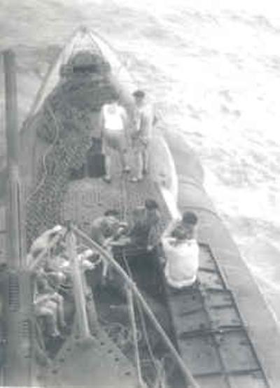
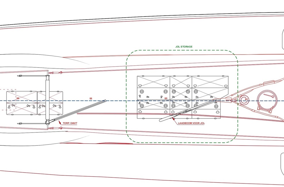
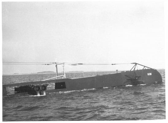
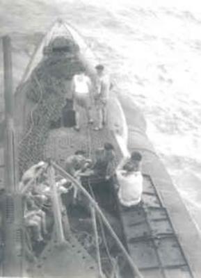
Thank you all for your likes, really appreciate it. Kevin, Paul, Borus and Ian, thanks for stopping by and your encouraging comments. @ Borus: Thank you for your consideration but it may take some time yet before this build is completed. We'll see how much time I can spend on the O 19 and then also the VOC ship model. @ Ian: Well that makes two of us I also had no idea till I saw the video of the crew rescue by the USS Cod in July of 1945. Fortunately I was able to obtain the drawings of the dingy from a good hearted Dutchman I took a few more pics late yesterday that I didn't post last night. Will do so next post. Cheers,
-
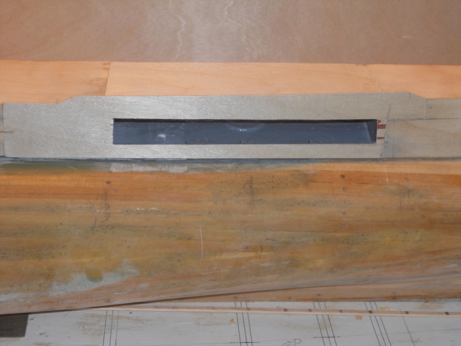
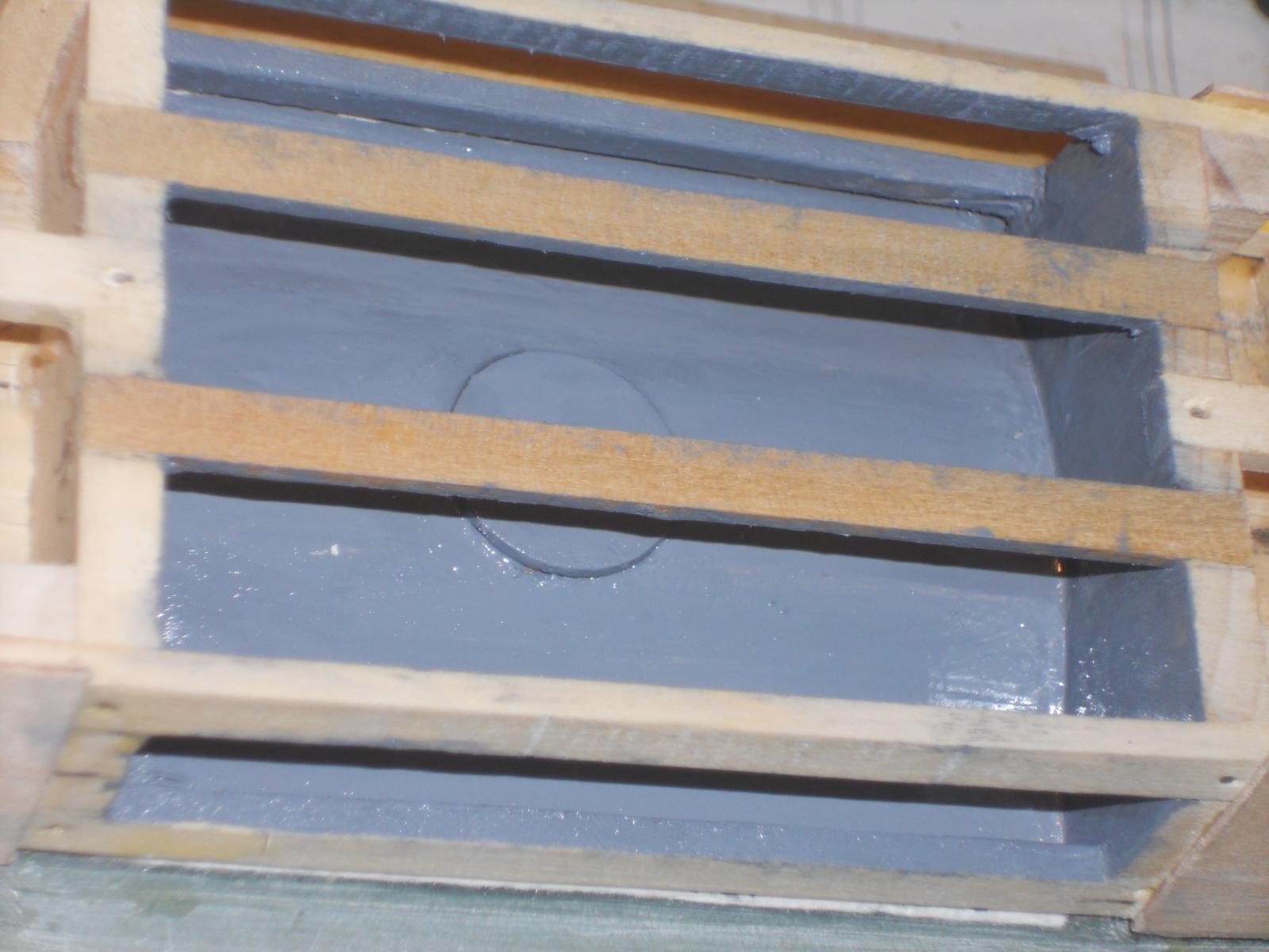
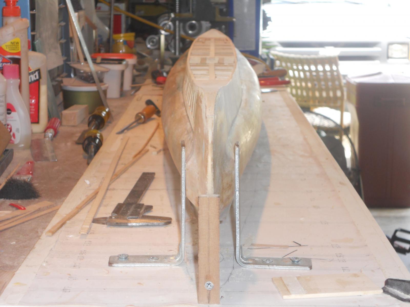
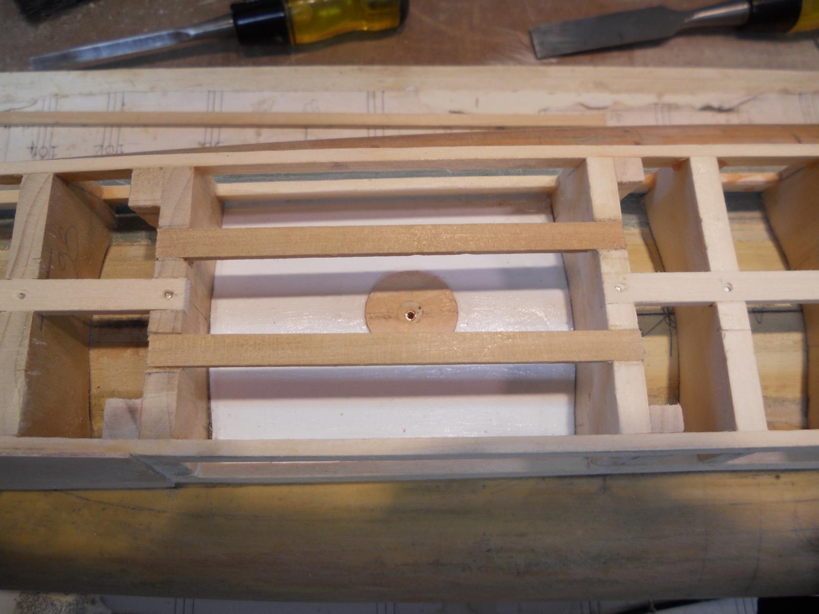
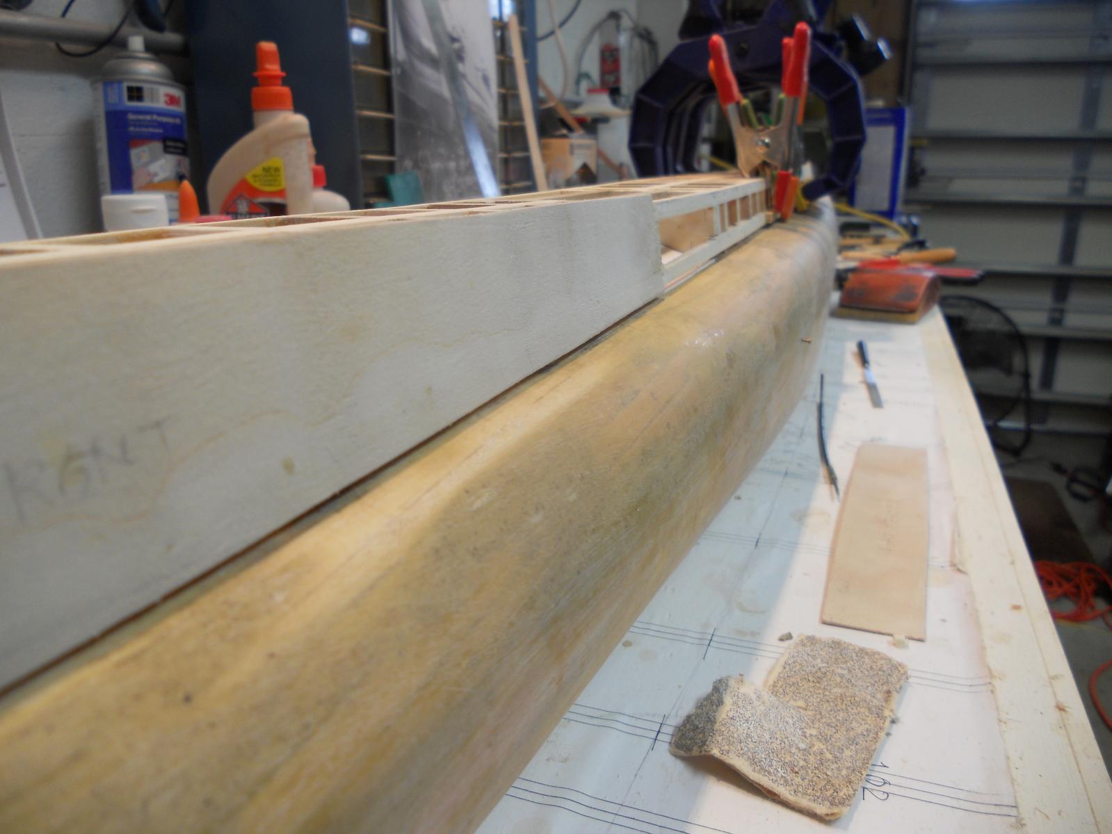
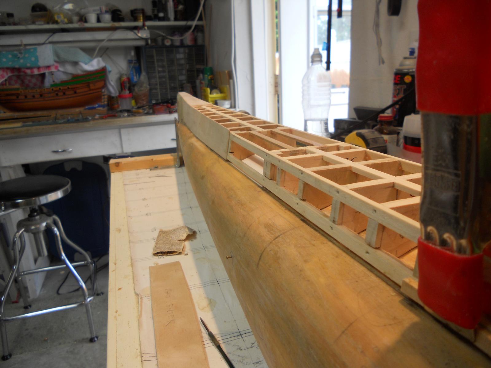
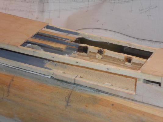
Hello all, Today was rainy with T storms and had to postpone some needed yard work and could spend some valuable time in the garage / shipyard. I had to do some surgery to one of the deck frames to make some more room for the dingy. I thought I had it figured correctly but according to the photos of the disaster on Ladd Reef and the drawings Gino den Ridder supplied the dingy sits at an angle under the deck plates behind the con. It just so happened that I forgot to allow the space for the bow of the dingy that comes to port side of the con. No problem, I just cut the port side half the frame away and made a new frame just ahead of it. I had that done last Sunday afternoon. I also made and installed the longitudinal deck support beams that will also function for fastening the hinges for the dingy "hangar" doors. Gino and I are still talking about the door configuration whether they are also hinged in the center like a by-fold door or a one piece affair. For now I'm not too concerned about it, that'll come later when it's time to put the dingy inside on it's cradle. From a strictly engineering point of view a by-fold would not be rigid enough and the photo doesn't show it clearly enough. I made a round flat piece for the deck torpedo assembly to swivel on and put a brass tube in the center to act as the pivot point. I also cut some heavy drawing paper to fit on the pressure hull in the deck torpedo "house" and the dingy "hangar" to act as the steel plates. They will be painted gray later before I put the deck plates on. Oh dear, that can be tomorrow already More pics! I also pre-cut the deck structure side plates and deck plates, done last Friday afternoon. Sunday morning was lawn mowing time before the T storms would hit again. Today I managed to glue the port side plates on and part of the starboard side plates. From the dingy location to the stern I used CA gel because there was no way to clamp it there, the slope of the sides are too steep. I had to glue it in stages so I could press it against the frame by hand and hold for 60 seconds. Worked like a charm Okay, below are a few pics for clarification on the progress. With the O 19 on Ladd Reef and the dingy compartment doors open. Gino's redraw of the deck drawing. It shows the location and configuration of the dingy compartment doors. Top view of the deck torpedo housing with the pivot plate and pivot tube. The paper steel deck plate glued on and ready to be painted gray. Port side view of the deck torpedo housing. This shows the forward deck side plate glued on, looking aft. Looking forward to the bow with the forward side plate glued on. To the right is a clamp for the aft side plate being glued. The sloop compartment from above and looking forward. The mod I had to make on the port side is clearly visible. Also the longitudinal deck supports and door hinge attach points is seen. Here too I glued on a piece of heavy drawing paper to simulate the pressure hull skin. The most aft part of the con ends at the center of the modded frame where that center whitish piece of wood ends. A side view of the sloop compartment. A view from the stern looking forward with the deck side panels glued on. I used the admiral's Nicon camera on macro, that made it a little out of focus for the forward part. Better next time Cheers,


-
Hello Kevin, According to what Gino den Ridder told me these deck torpedo launchers did leak a little. I wouldn't call it leaking like sieve but I guess they needed to have bucket hanging under it But they only leaked when submerged You know, I never heard my father complaining about it though, so it must not have been too bad or else they just lived with it. Cheers,
-
Same here, 30 is nice. 47 is kinda warm all right. That reminds me of the days I had to witness an NDI inspection to the wing frame 55 on a DC-9 in Marana, AZ. in August. It was about that in the shade! For some crazy reason it didn't feel that hot. Dry heat they say, my foot, it was hot. Have fun,
-
#8 degrees C too hot? Hmmm, I guess for yuns thick blooded Dutch people I can agree to that. 38 is the temp in my garage, aka the shipyard, and I'm loving it . What the heck am I talking about, I'm also a Dutch people but born and raised in the Dutch Colonies with thin blood, love the heat Of course I have the doors open and a floor fan going full blast! Quit comfy I must say The admiral shakes her head, how can you stand it here in this heat and slinks back inside the ac cooled house. So far the temps on at the north east coast of the US has been relatively mild, so far, only 32 C but the humdeditty is way up there so it feels hotter then it is. No prob for me though, a quick garden hose shower and I'm good to go , back to the garage and work some more on the models. Happy modeling all y'all and cheers,