Piet
-
Posts
3,568 -
Joined
-
Last visited
Content Type
Profiles
Forums
Gallery
Events
Everything posted by Piet
-
 Hi Popeye, well, it's slow going right now, too many other chores that interfere and we must keep the Admiral happy Hello Boris, yes you can. Let me know what you need via my private e-mail. Well, today was not a total loss though. I managed to fine tune the position, i.e. square up the prop shaft assembly to the keel. I also tapered the aft end of the rudder brace/keel support. Looks better. I'm also in the process of making the prop shaft fairing pieces and bunch of other detail items. It'll most likely be Monday at the earliest I can get back to the boatyard, aka garage. All y'all have a great Labor day weekend, that is for the Americans among us, the rest have a great (short) weekend. It's great seeing Adriaan back in the dockyard and hope Sjors is getting better too. Cheers,
 -
Hello Adriaan, good to see you up and at it again! Keep it up mate. Cheers,
-
Hello Michael, thanks for your kind comment! The plywood, yes, I wanted to try doing it and didn't want to drive 30 miles to Hobby Lobby for a sheet of 1 mm. At least I can now say that about 99 % is really scratch build. Hey, I'm retired and besides a few home related chores what else is there? Okay there is drawing, painting, hiking, photography and etc. Cheers,
-
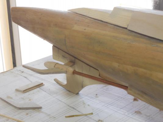
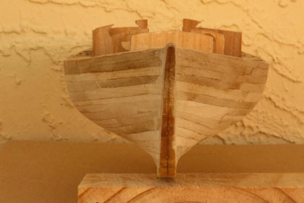
Thanks everyone for your like votes, much appreciated! Hello John, thanks for looking in and your most kind comment. Yes, I guess this part of the build is perhaps the most complex of all. Although I am not even thinking about the deck launch torpedoes, the deck gun and the A A guns. I'm taking it one section at a time. I was able to work a few more hours on the boat and made the diagonal braces for the prop shaft bearing housing. I also shaped the outboard dive plane hinge braces and installed two dowels in each. Nothing is assembled yet because there is still some fine-tuning and adjustments to be made. I need to figure out what steps need to be taken first and in what order I need to proceed from here. Many small and not so small details to do and I don't want to get caught in having to remove something or try to work around something that's in the way just because of being impatient or not thinking ahead I may use two part epoxy cement to fasten this assembly to the hull for extra strength and it allows me some time to position it in the correct place. The pics below may not show much difference with the ones in the previous post but some of the parts are new and some are remade because I was not satisfied with them. Okay here are some pics with comments. Stern end view. The new diagonal braces are pinned and glued to the prop shaft bearing housing and so are the small horizontal braces but the whole assembly is still temporarily stuck on and hanging by the prop shafts through the bulkhead. The two outer dive plane braces are also still temporarily stuck to the bearing housing. They will most like be the last to be cemented to the bearing housing. Some metal work is yet to be done to them like the net cutters at the leading edge and the dive plane hinge receptacle. Top view. The pencil marks on the dive plane hinge braces are areas that need to be removed for the brass plates for the plane hinge receptacles. I may use two part epoxy cement for that. I may do the same with the net cutters at the leading edge. btw, these braces are made by glueing three layers of 1 mm plywood, they are nice and strong. Another view from the top. You can see a hole in the trailing edge of the diagonal brace, that's for a dowel to attach it to the hull. I also need to make a fairing for the area behind where the prop shaft comes out of the hull. I will most likely do that with all this stuff off of the boat, that's another reason for waiting. btw, that brass strip on the right side of the rudder hinge/keel is for the rudder hinge fixture and will be cemented to the bottom of that assembly. Some of the wood still to be removed. Port side view. The dowel hole in the diagonal brace is now easily visible. Close-up shot. I have already shaped the inboard braces for better hydrodynamic performance Looking aft on the starboard side. The diagonal brace still needs to be hydrodynamicaly shaped, it was still in the process of glue curing. Cheers
-
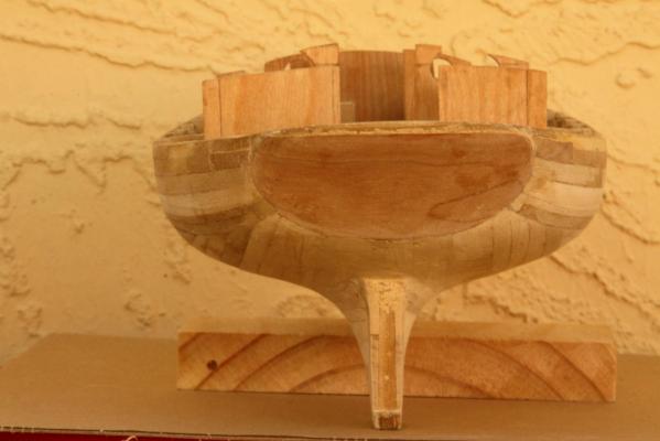
First of all my sincere thanks to all for your like votes, really appreciate it. Hi Bob, thanks for keeping an eye on me and my build. I like your new project! Well, sticking to the actual ways of building a boat or ship should be the challenge for us. I just ran out of patience and figured that with the boat painted it was just too time consuming because I wanted to start with the VOC model. At least that's my story and I'm sticking to it Today I'm showing all y'all the next stage of the build, the start of the interior. There are obviously many steps between my last post and this one I have not photographed, shame on me, just too busy building As mentioned some time ago I made my own thin plywood for the interior paneling. I had some 1/4 inch plywood from Home Depot left over that I used to repair a friend's speaker cabinet and the finished side was cherry, nice looking veneer on a junk core. The back side was a light colored wood veneer of an unknown type of wood. I cut 6 inch wide planks and carefully separated the veneers and then glued the two finishing veneers back together. I wound up having nice stiff but still bendable planks. I left just a smidgen of the core but hardly worth mentioning. The biggest aggravation with the poplar wood I used for all the framing was that it "fuzzes" a lot. I couldn't get rid of the wood hairs. Fortunately most is hidden but it sure makes the pics lousy to look at before everything was covered. Okay, the pics can tell the story better. I'll also make a few comments. With the home made plywood I paneled the head and the main cabin area. I also made the lower two bunks. Unfortunately I didn't make a picture of the inside of the "potty," it has an actual bowl with a pipe going down to the imaginary dry-chem holding tank. And yes, the lid actually hinges to allow one to do their "duty." The wash basin is from a plastic safety stopper of a milk carton. The spigot is made from a copper tube and the faucet is from copper wire. Aft of the bunks are hanging closets where I eventually made small lockers on the top. All of them will have workable doors. I made a bunch of hanging knees for the deck support framing and fastened them to through the paneling into the frames. Okay, I just glued them to the paneling A close-up of the head. On the forecastle bulkhead is a small closet for "potty" supplies. As mentioned above the lid actually hinges, perhaps you can see the hinges in back of it. Everything is still in the rough. Close-up of the wash basin. There is storage space below the sink and the waste water is piped overboard. As mentioned it's all still in the rough and unfinished and full of debris. A close-up of the entire cabin and head area. The door to the forecastle opens towards the port side, you should be able to see the top hinge. I still needed to make the handle when this pic was taken. Cheers,


-
Hey Steve, don't sit down just yet. A bayonet??? You'll have one sore tuchus my friend Cheers I'll drink to that.
-
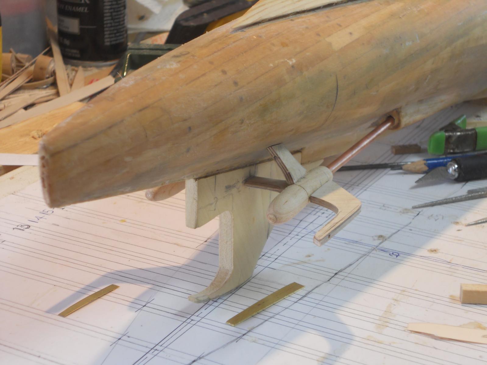
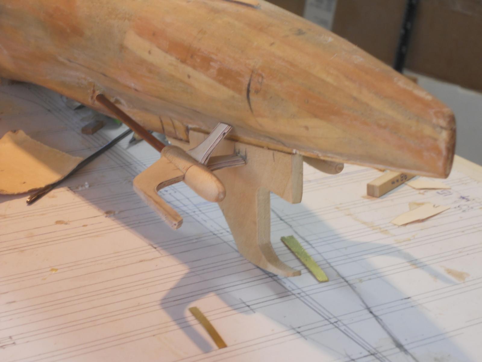
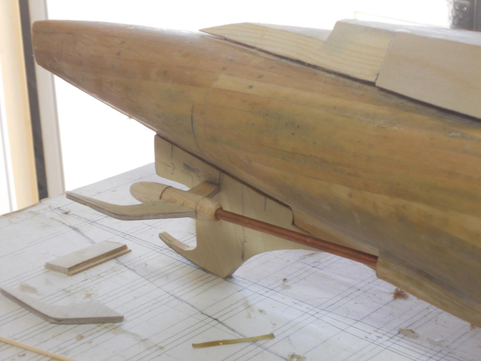
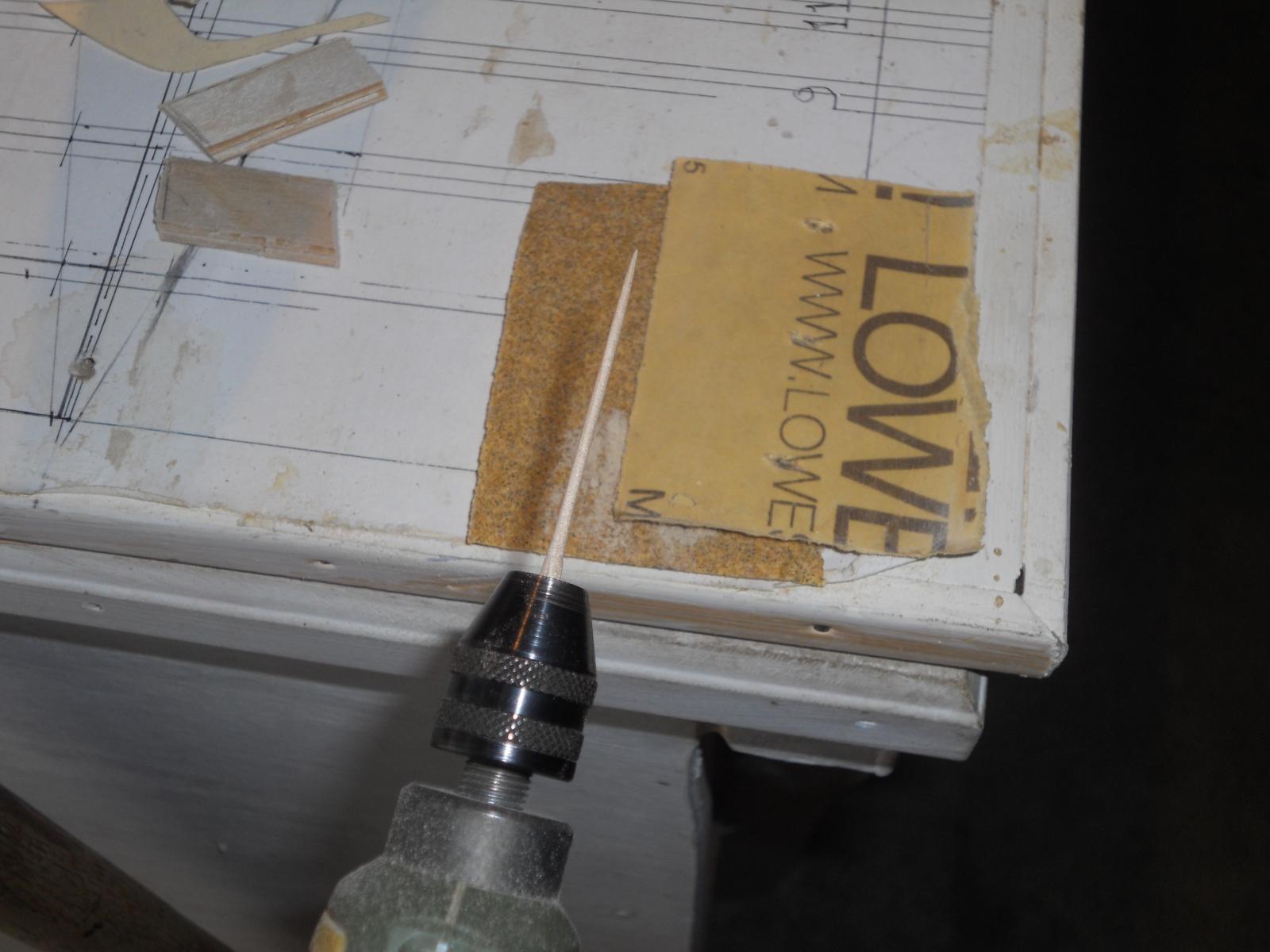
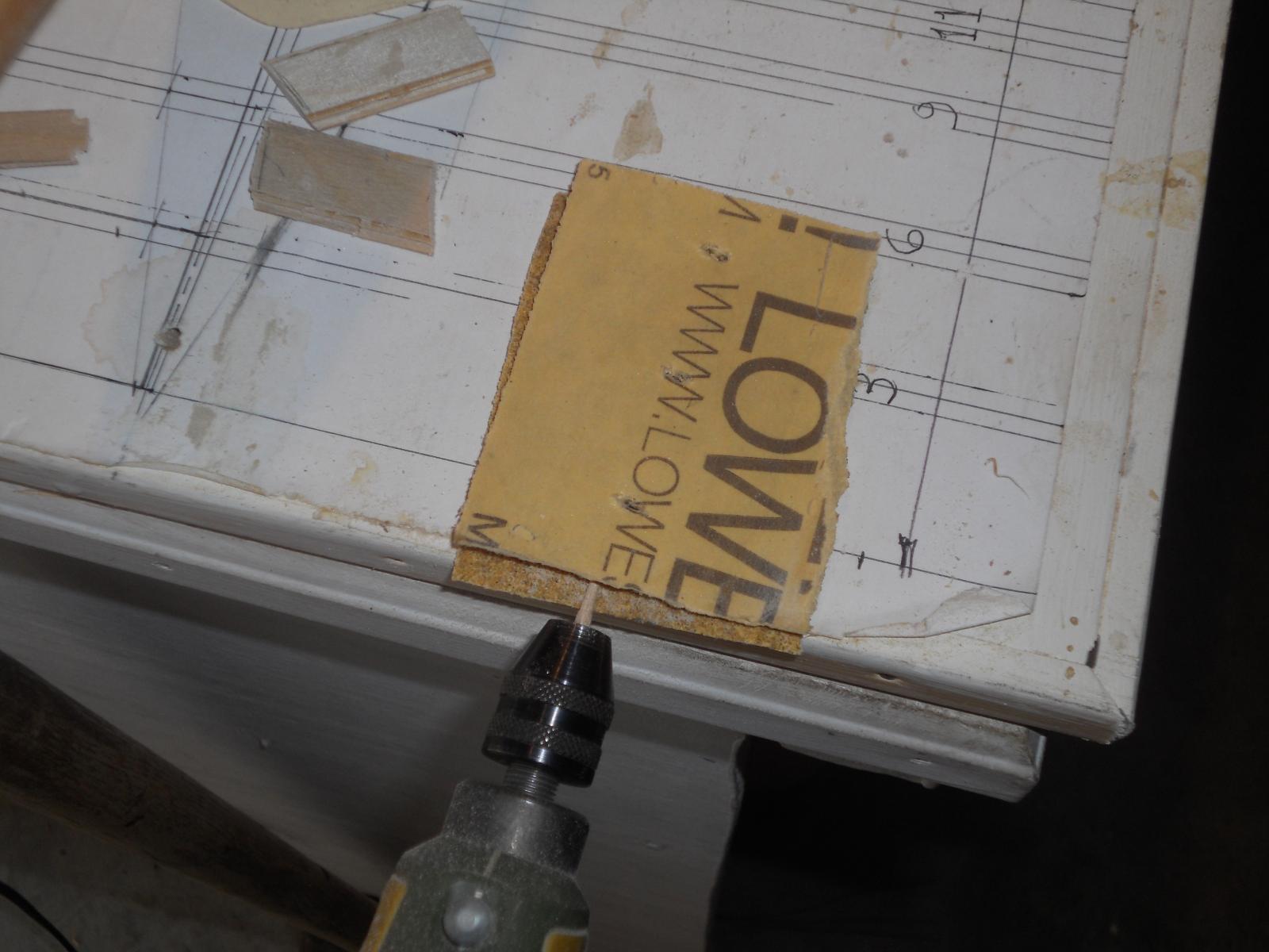
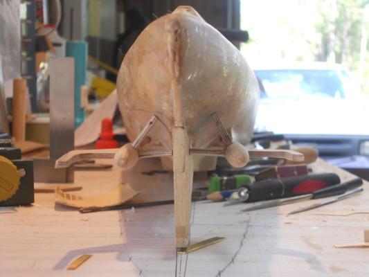
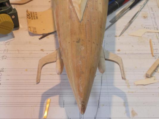
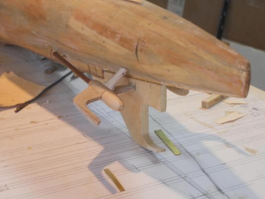
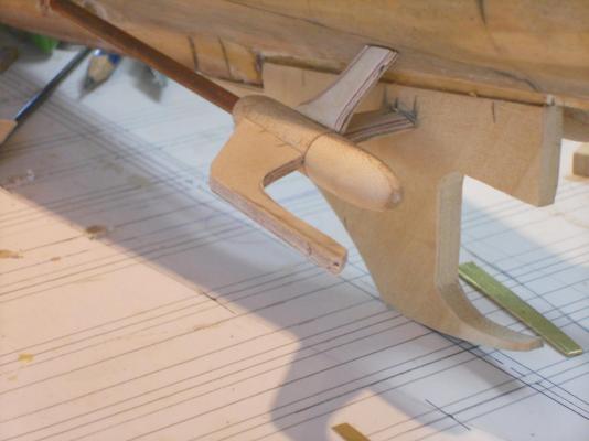
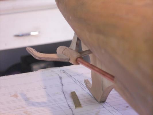
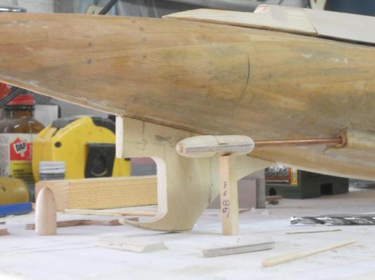
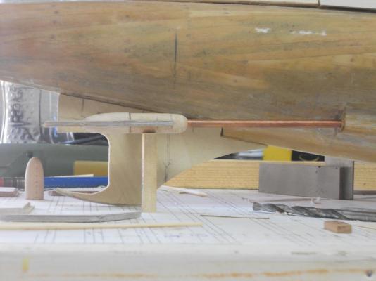
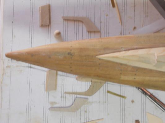
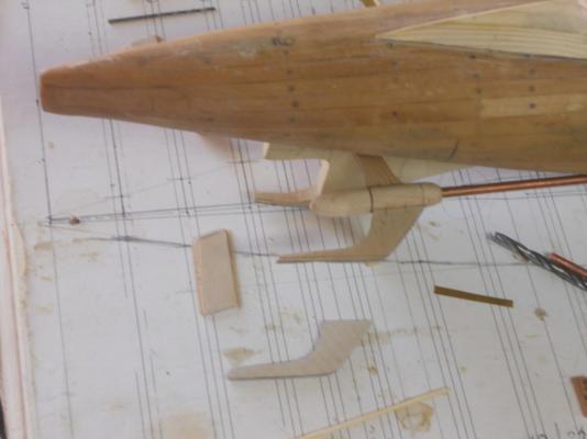
Hello friends, it's been a semi productive day today. I say 'semi' because I am also in the process of writing a bunch of recipes to be included in a cookbook that'll be produced by our financial advisor. Most are old Dutch and Belgian recipes I remember my mother and grandmother used to make and a few from my home town, Surabaya, Indonesia (the former Dutch East Indies). The new dive plane hinge braces turned out great. much better then the previous ones. They still need finishing and fine tuning. I also need to put the net cutter teeth on them and the hinge sockets. The challenging part was drilling the holes in the end bulkheads for the prop shafts. There was not enough space for my small Proxxon hand tool and the flex shaft could not hold the drill bits I needed. So, I took my long 1/8 inch aircraft drill and voila, I could at least drill a 1/8 inch hole, it was a start. But now what? Okay, I took a #19 drill bit, 0.166 inch, which is a tad larger then the 5/32 inch shaft housing. I tried to rotate it by hand but that was VERY slow going and uncomfortable to my delicate fingers. I got myself a small pair of pliers and rotated the drill bitt that way while putting pressure on it with my left hand thumb. It worked and I got through Yeah, yeah, I know, I should have drilled these holes before assembling the frame to the hull. Next step is to measure the length of the diagonal side brace between the prop shaft bearing housing and the hull and cut it out. I don'y know if I can use dowels on both ends of this brace, I may have to drill diagonally through it at the hull side and then insert the dowels. I like to secure the prop shaft rather well because that whole assembly sticks outside the hull and is rather vulnerable. But all of these details will work out as well. I have over 60 years of mechanical experience to fall back on Well, here are a few pics that'll tell the story. I calculated that the distance from the bottom of the bearing housing is 38 mm from the base line of the boat, which is the surface of my build dock. This assures also that the prop shaft is parallel to the waterline as well as the base line, i.e. the build dock. The dive plane hinge brace is seen head-on. Looking it this pic I think I'll taper the rudder / keel brace aft a little more. It looks kinda fat in the rear. That bullet looking thingy you see standing up on the build board is the propeller hub for the port side assembly, still in the works. You can also see the "difficult" hole I had to "worry" through. I also need to fair in the part where the shaft comes out of the hull. I need to "sculpt" a piece of basswood for that. Another thing I should have done some time ago. Ah, those little jobs that were easy to do are now more difficult, but that keeps the old grey matter active Another shot almost straight on. A seagull's eye view of the assembly temporarily in place. I also temporarily stuck the previous dive plane hinge brace on. Below it you see the new one. To the right you'll see the large drill bit I worried through the bulkhead. I also filed a small copper tube to a sharp end and used that as a round chisel. It kinda worked but didn't use it on the port side. Aft of the assembly you see a small rectangular piece, that'll be for the diagonal brace. Another view from diagonally above. I may have to shorten the prop hub some to allow enough space for the dive plane in front of the hinge. Looking aft at the assembly without the diagonal brace, which is waiting to be made. Still a lot of work in detailing to be done. Cheers
-
Hello Bob, what a great decision you made. This tug is well worth the effort to commemorate it's distinguished service career. I'm with you, I love tugs! No matter what function, harbor tugs, seagoing tugs or what ever era. They exude power and have character. I'll be following along. Cheers,
-
Hello Kevin, good to hear from you! As a quick response without looking further into it I'd say off hand the diameter of the prop is 1.9 meters. It has three rather round blades. Perhaps Gino den Ridder, my mentor, has the correct measurement handy. We'll check. Cheers and thanks for stopping by,
-
Hey Cap'n'Bob you mean to tell me there is another one who "cheats" once in a while ? If I ever get to building another sloop in a larger scale I'll stick to the book, promise Hello Harvey, thanks for dropping in. Did you get a glass of Belgian beer and some popcorn? Beer was in the fridge and the popcorn is on the dresser. Ah, yes, the interior - - - - you aint seen nothing yet my friend. Wait till we get to do the interior furnishings! Talking about tedious work - - - - that's why I would like to build a larger scale to really do it justice. More to come soon! Cheers
-
Thank you Cap'n Bob, the planking did come out okay although I did not follow standard procedure. But who is to know now that she is painted Just don't tell anyone, okay? Cheers,
-
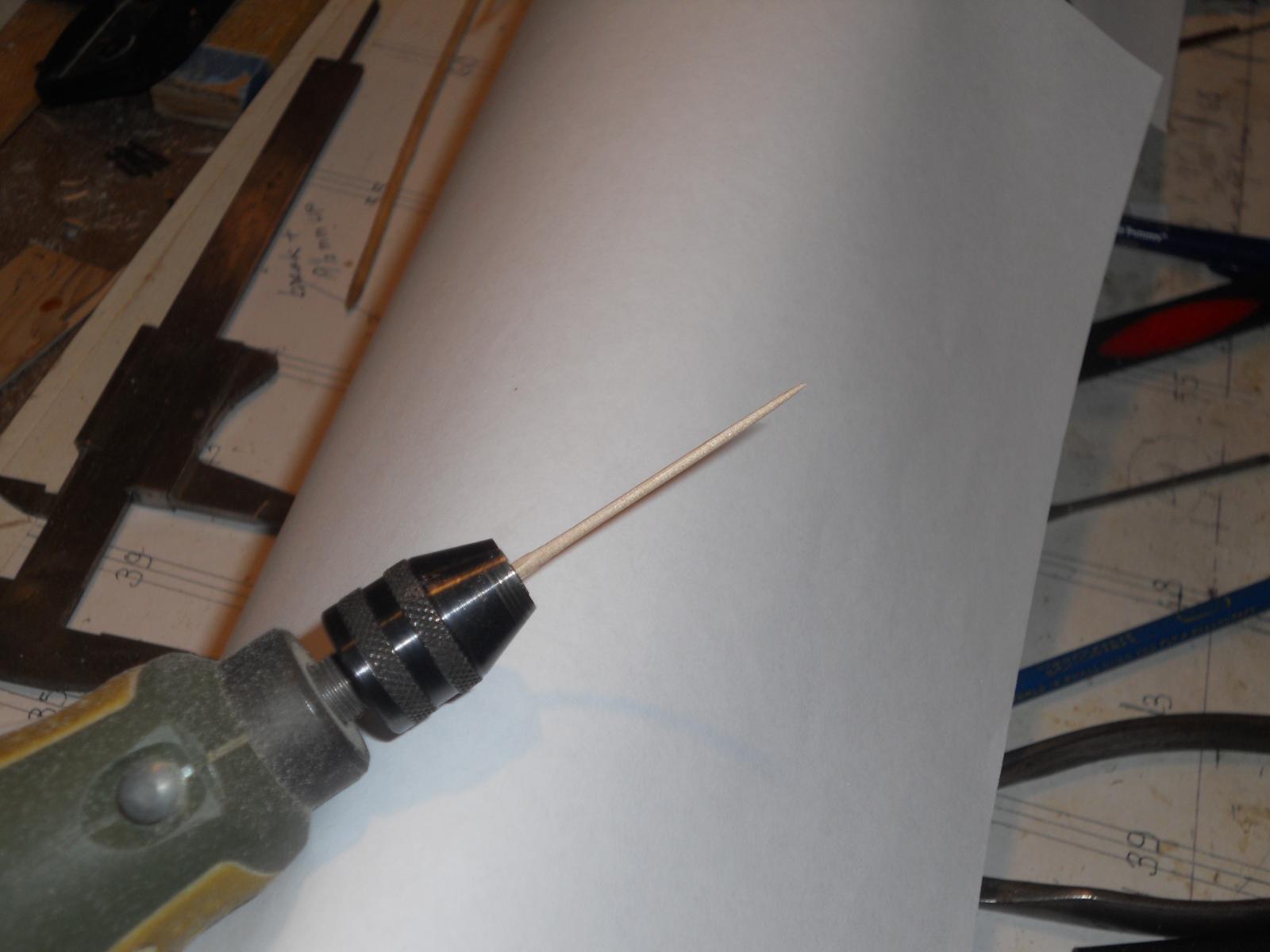
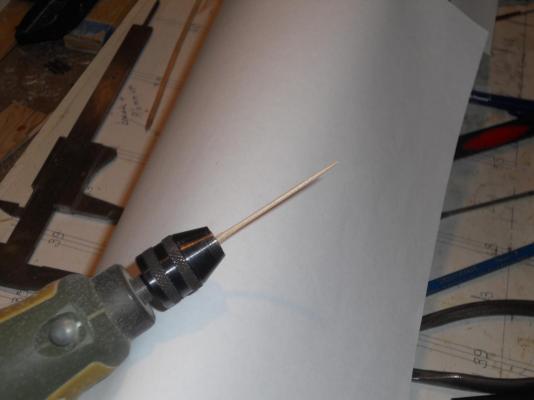
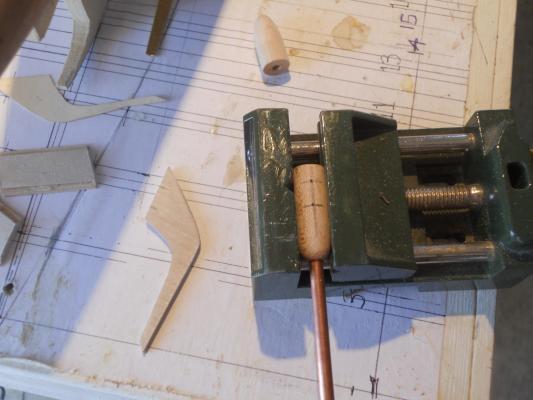
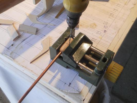
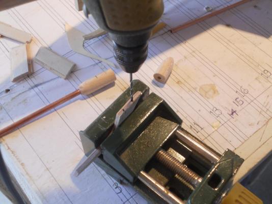
Hello friends, I had some time today to do some work on the boat. Last week I glued up three small pieces of 1 mm plywood to make the dive plane hinge supports and cut them out according to the sketch I made. Today I made the dowels to fasten support struts from the screw shaft bearing housing to the hull and the dive plane hinge supports to the prop shaft bearing housing. There is one more support strut from the bearing housing that runs diagonally up to the hull. I have not shaped them yet, still pondering when to do that. I'll most likely have to build a jig to locate this whole assembly correctly. Everything is measured from the base plane, which is in my case the build board. I drilled the dowel holes and proceeded to assemble these parst on the starboard side when I discovered that the dive plane hinge support piece was angled inboard too much. Soooooh, scratch two pieces of work and remake them. Yeah, they are currently glued up and curing under a few steel bucking bars. Tomorrow I'll finish shaping them and dry check on the boat. I got tired of pulling the bamboo skewer sticks through my drill index to reduce them in size. So I devised another method that worked a lot faster. I mounted the skewer in my Proxxon hand tool and placed it between two pieces of sand paper. Wow, that worked a lot faster but I had to watch out because it has a tendency to take too much off at the tip. Pics below show my mad method Pics below of the progress or lack thereof. Skewer mounted in Proxxon hand tool. see what I mean with the end? Most of the skewer was usable though. Ready to put between sandpaper. Sanding the skewer. Ready to dril holes for the dowels in prop shaft bearing housing for the dive plane brace. Ready to dril holes for dowels in prop shaft bearing housing for the support strut to the hull. Ready to dril dowel holes in the dive plane hinge brace. Both the prop shaft bearing housing support brace to the hull and the dive plane hinge support brace are doweled and temporarily attached to the prop shaft bearing housing. Here I already noticed the potential problem. What does one say under these circumstances? Well, first I scolded myself, "you dumb @%*$ - - -" Tomorrow is another day with some hot and sticky weather. Cheers,


-
Hello Boris, Great work, I love the final box picture! One more thing I noticed though. I only see three step cut-outs on the side of the conning tower. There should be four. I have indicated where the missing step should be on the pic below. Hope you don't mind. Cheers,

-
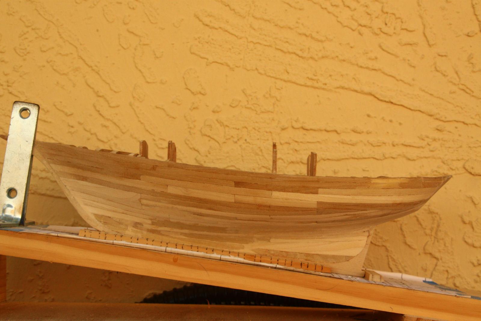
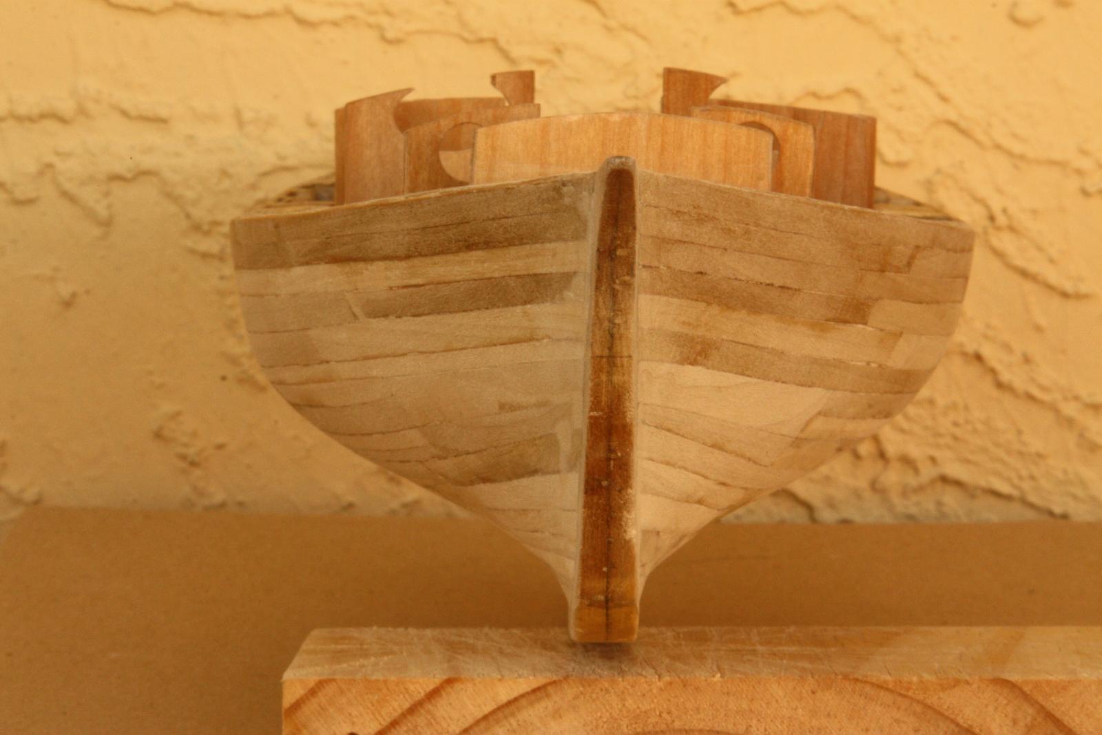
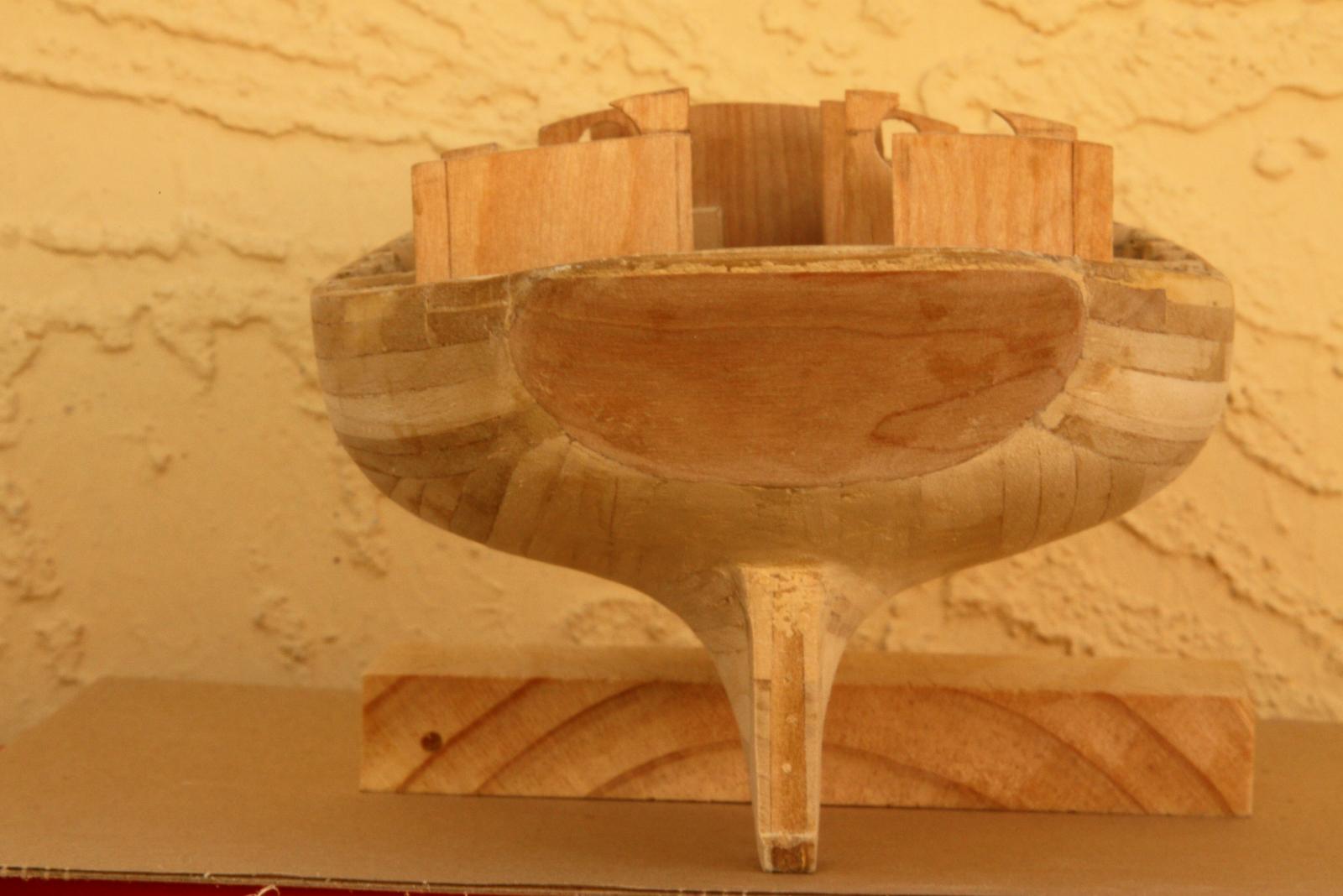
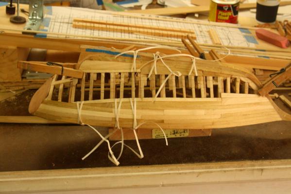
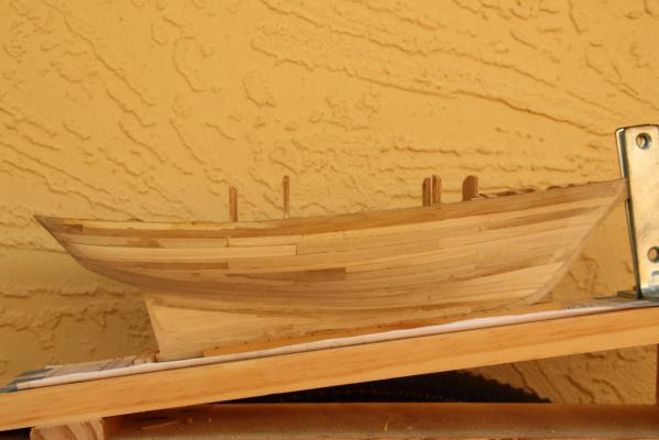
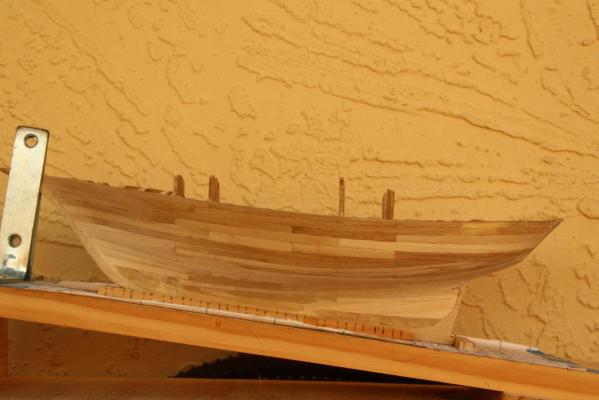
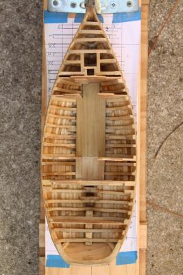
Hello friends, Good news, the Admiral, Gwen, made it back home safe. She left at 05:50 from Coraopolis, PA (a suburb of Pittsburgh) and pulled in dockside at the shipyard at 18:40, 13 hours on the nose for 900 miles. Needles to say I had very little time to devote on ship building in the last few days, lost of little chores and talking. She wanted me to cut off the nut branches of our queen palms. A messy job. Even so, I managed to do some work on the O 19 sub this afternoon. So this evening a like to add a few more pics of the sloop. I have only one picture of the planking, I figured all y'all know how to plank boats and ships and besides, there is a great tutorial right here on MSW. I used a little unorthodox method as you'll see but it worked for me. The white strings you see are aircraft rib stitching cord, left over from my previous life as antique aircraft restorer. Yes, I also used clothe pins clamping the planks to the ribs and large C clamps. The cord also ensured a nice close seam. It's obvious that I didn't really follow the planking tutorial, I wanted the hull closed quickly and was not too concerned in following the standard practice, Yeah, yeah, yeah, I'm a bad boy I figured that it's going to be painted anyway so why "wasting" so much time. I learned enough for the next planned project, the VOC ship "Surabaya." Which btw worked out just fine. Oaky, the pics will tell the story. One of the stages of planking in progress. Starboard view of the planking completed. Some sanding was started. Here I had not yet lowered the tops of the cabin bulkheads. Port view of the completed planking. Some sanding was started and you can see that I added some wood filler in spots. Top view of planked hull. I also completed gluing in the cabin deck planks. The forecastle access door is clearly visible and I framed the forecastle hatch and mast holes. Bow view of planked hull. You can see that I added a little filler where the planks met the rabbet, it was a little rough. This and the following picture were taken after I cut down the tops of the cabin bulkheads. It proved to have been the right decision. Stern view of the planked hull. This shows the cut down bulkheads really well. I had to use just a little filler on the transom. Overall I had to use very little filler, Everything flowed quite nicely. Cheers,
-
Hello Boris, It is looking much better but could be lowered just a little more. I copied your picture and drew lines as I believe they will then be about correct. Don't make the part above the deck too high. On the real boat it could be about 150 to 200 mm above the deck. On your picture it seems just a very little bit too high. Same amount above deck level as below deck level. I like the detail of the deck gun and the conning tower, real nice. Also the cover picture for the box, love it ! Really, really great Top edge of opening just a little lower and the bottom edge also a little lower plus a little more to make the opening a little wider. The launcher must then also be lowered the same amount as the top edge, this will give you a little more clearance below the launcher for the closing doors. Cheers,

-
Hello Boris, I like what I see on your O 16 or K XVI sub model! Is there a chance you start from the beginning so we can follow how you do it. Unless it's a secret Did you understand what I tried to explain to your post on my build log? It is in regards to the deck launch torpedo launcher opening and side doors. That would be the only change I recommend you make to the model, if possible. It may mean lowering the position of the launcher a little and also lowering the bottom sill of the opening a little. The Google Translator may not translate it all clearly and perhaps you can find an English speaking friend in your area for help Unless of course you speak, read and understand Dutch Cheers,
-
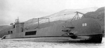
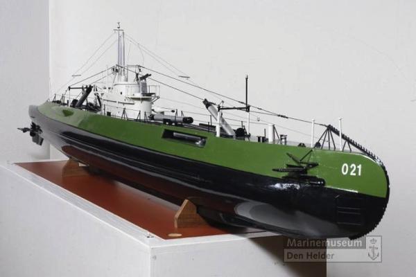
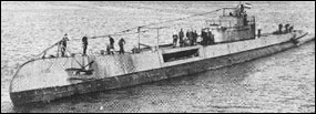
Well, the Admiral pulled up to the dock at 1850 in the MC "Gwenmobile." (MC stands for Motor Car ) She was tired but glad to be home. (Me too ) Hey Boris, that's a magnificent piece of work, very nice looking . Now about the upper part of the launcher opening. Let me put my (unofficial) engineering hat on. The entire deck structure is what I call secondary structure. It is not subject to any substantial forces and can be of a rather light construction. It's quite similar to the Fokker F-70 and F-100 where the cabin floor structure is secondary, it only has to carry the weight of the seats and passengers. For the submarine, In order to span that large opening without the vertical structural members on the sides a heavy primary structural member had to be installed at the top sides to function as a bridging beam for the lighter deck frames. It appears that these heavy beams extend somewhat down into the side opening because they had to be fastened to the forward and aft top stringers. What type of beams they are, I don't know but my guess would be T beams on their side. The span-wise deck frames are either riveted or welded to the horizontal portion of the T beam. This is similar as I had to design for a few of the aircraft of an airline I was the director of QC and Engineering for. The design was for the bridging of the cabin floor over the entire wing root that ran through the fuselage, which was primary structure. I used aluminum I beams though. In my rework on my model I tried to make the span-wise deck beams as thin as possible, about 3 mm. The top of the door opening is even with the bottom part of the deck beams. This does not give me anything for a doorstop on the top. I will be forced to extend the top of the side plates down 1 mm when I put the paper side panels on. Even so, I think it will look similar to the photographs we have of the O 19, O 20 and later models. I may revise my thinking and device another method to act as the doorstops. What Gino is talking about is the actual doors. They hinge on the bottom and fold down not quite onto the top of the pressure hull. The two doors on the actual torpedo tubes have two very heavy hinge brackets on top that stick up above the launcher assembly. That's what makes the space on the top of the opening quite critical. On my model I calculated the hight between the top of the pressure hull and the top of the deck for my scale and cut the deck frames accordingly. I also calculated the vertical measurement of the launcher assembly itself and have just enough space to let it come through the side opening with perhaps 1 to 1 1/2 mm to spare on top. So I believe that what I have is close to accurate. I see no problem to make the side doors fold down enough for the launcher assembly to rotate over them. I am attaching a few pictures that show that the top of the side opening is below the top of the deck. This is what I am trying to achieve and I think that's what Gino is referring to. This is a rather small pic of the O 19 but it shows what I mean. This pic was taken in Scotland after her refit in 1944. They removed the doors but the upper part of the door structure is clearly visible. As the picture show this is a model of the O 21, quite a nice model. Here you can see that the side doors are laying flat on the bottom. Cheers and keep up your excellent work,
-
Hey Frankie, how about the monster having taken the top most parts of the masts down that are now hanging by their rigging lines? One could even still be in one of the tentacles. Love the idea, great suggested story line. Cheers,
-
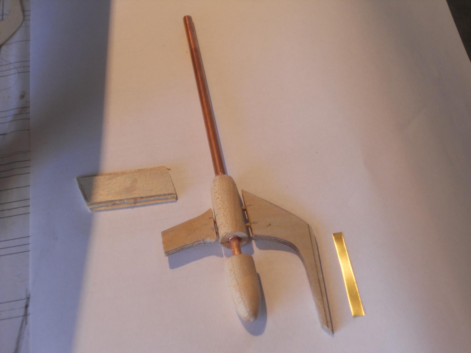
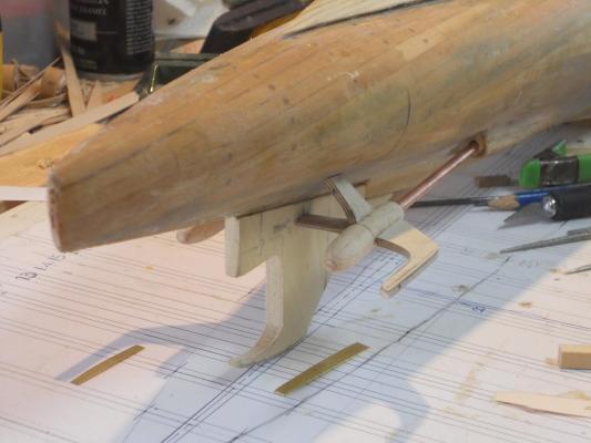
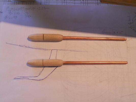
Today I moved to the stern area and started to make the propeller shaft bearing housing and the prop shafts. Next will be the dive-plane support. That'll be attached to the prop shaft bearing housing, which in turn is supported by two struts to the hull. Before I can start with the dive planes, rudder and propellers I'll need to take some time off the builds to clean the house a little, do some laundry and cook a few dishes my wife likes. She is driving back from Pittsburgh, PA this coming Thursday. 900 miles in 13 hours. 72 years young! There is a problem though, there is rain expected on most of the route and she dreads rain when driving. Wish her well. This shows both the port and starboard side prop shaft assemblies. I used oak dowel and turned it down to the scale size of 10 mm diameter. The same for the propeller blade hub. The total length of the housing and hub 38 mm. I used my Unimat DB 200 lathe to turn them and drill the holes. I used copper tubing for the shaft housing and for the shaft itself, which is inside the housing tube. Sorry, for got making pics of the turning process and also the part layout. I placed the assembly on a paper cut-out for the dive plane support. I also glued and pinned the rudder hinge and keel assembly, so I can now also make the rudder. Cheers,
-
Thank you all for your "like" votes, much appreciated. Anthony my friend, you have the talent, just look at your nice little yawl! That thing is awesome. Michael, thanks for dropping in and actually I would build a 35 foot sloop at 1:12! That's a nice scale to get a lot of good detail. I'll also use better wood. May not have to make my own plywood Thank you Cap'n Bob, Yes, she's really beginning to show her fine lines. The Admiral (Gwen) also likes her and it's currently proudly displayed on the dresser in the breakfast nook. Talking about the Admiral, she's driving back Thursday from Pittsburgh, PA. 900 miles and 13 hours on the road. She's one brave lady. Problem is though, there'll be lots of rain on the way and she dreads driving in the rain. Keep our fingers crossed. Cheers to all,
-
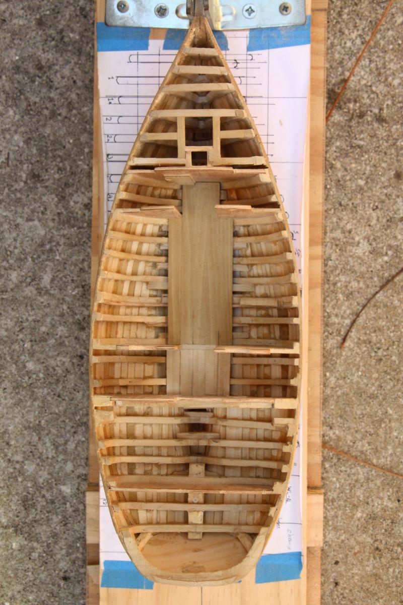
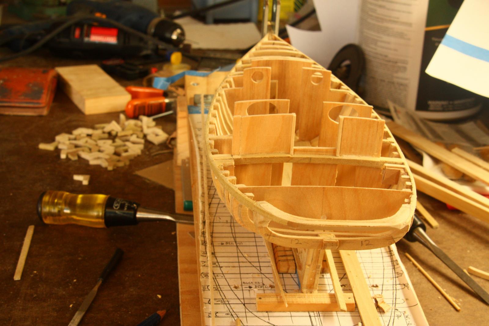
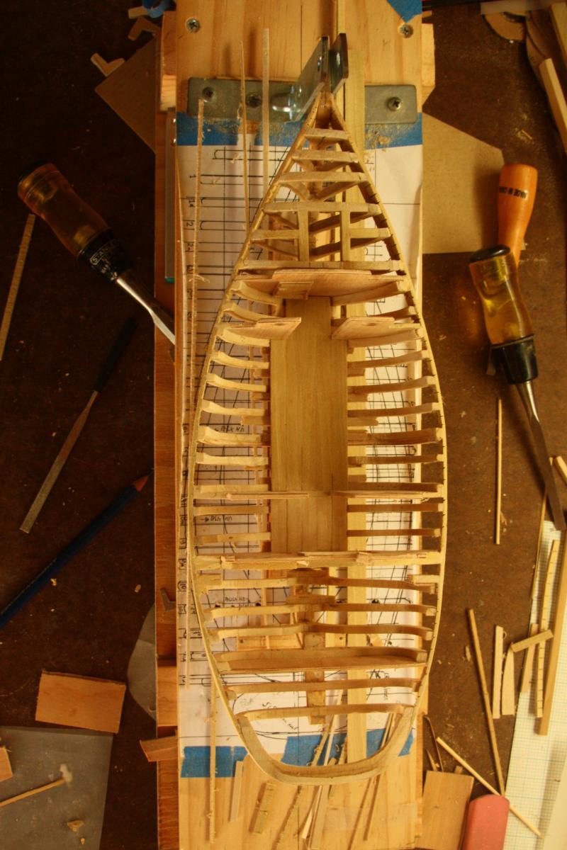
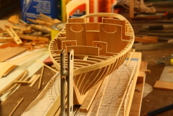
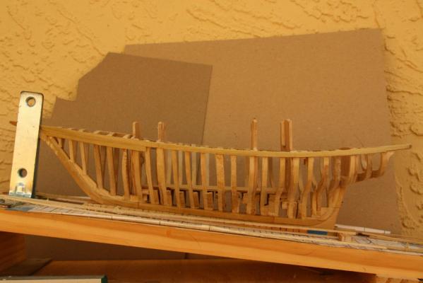
Thank you all for your like votes. I shall not bother showing the temporary placement of all the frames, you've seen one then you've seen all There were two frames I had to remake because I found out later when putting the shear batten on I must cut them on the wrong pencil line. There are several pictures I forgot to make in the build op to this stage. At this stage I had made the forecastle bulkhead and all the other cabin bulkheads . As mentioned in a previous post that I made my own plywood from cherry veneer. I made 1/8 inch for the bulkheads and 1/16 inch plywood for the interior paneling and bunks. I also made an access door in the forecastle bulkhead to the sail locker where the generator with the fuel tank and potable water tank are. The door works. View from the stern with all bulkheads installed. The cabin deck planking was also glued in and you may see part of the forecastle door. looking at this pic and the next one from the bow I thought that the cabin roof seemed to be a little too high. It just didn't look right to me. You'll notice in future installments that I cut them down a little. Oh, there were a few other changes I made like adding small cupboards in the galley where the oval openings are. View from the bow. This pic really shows my displeasure with the hight of the cabin bulkheads. An aerial view. Here you can clearly see the door in the forecastle. The head, cabin and galley deck are on the same level. Right behind the forecastle bulkhead is the head and wash room. There will be a curtain for privacy. The opening in the deck framing ahead of the forecastle bulkhead is for the sail locker hatch and the mast. Port side side view. In retrospect I could have made the stern deadwood a little higher but it worked out okay with the frames extended. If or when I'll remake this model in a larger scale I'll certainly will do that. Cheers,


-
Hello Paul and thanks for dropping in. According to the drawings I have these trim planes have the net cutters but the guard above it has them as well. I think they are not much good for cutting steel cables or chains though. Thin stuff perhaps and definitely rope netting. Yeah, it does seem strange to put them on something more delicate then fixed steel things. Hello Skippy, thank you too for dropping in and you don't have to be silent you know, Sjors certainly isn't Yes, I'm having a ball with this model and let my VOC ship gather dust, shame on me. Yeah, sometimes pilots want to hand fly the airplane themselves instead of letting the autopilot do the job. That's when things get hairy Their excuse is then the weather, much turbulence Hey Sjors, I sincerely hope the medical professionals will fix you up. I'll be rooting for you. Re your bus, similar with pilots, all they know about their airplane is it got wings, a tail, engines and landing gear I have always wondered why they call it a landing gear and not a take-off gear Please get well my friend! Cheers
-
Hello Lawrence, Thank you very much for your undeserved compliment, but I'll take it anyhow You are not a slouch yourself with that very impressive Victory model. The fun part is figuring out how each part is or should be made when working without drawings or guidelines. I have to consult many old drawing,s paintings and museum models to get an idea and then also rely on a few experts on VOC ships. I hope you'll try your hand at a scratch build after the Victory is completed. After three models under your belt you should be past the learning curve. Get a good set of drawings and start making your own parts. There is nothing like it and the satisfaction is exhilarating. There is a lot of expert help if you need it. I have been neglecting the VOC ship in favor of my father's submarine model, the O 19. But she is sitting not too far away from my sub model, three steps. I really need to get back to her and put the gunport lids on on the starboard side. Then I can finish some of the deck furniture before starting with the rigging. Thanks again for visiting. Cheers,
-
Thanks to all who voted like, much appreciated. Hoi Freek, very ingenious! Great stuff! Did you also add the launching of the torps on video? Love to see it. 2 meters is quite a distance. Hoi Sjors, pneumonia eh. Nasty stuff. Just follow doctor's orders, take a few cold beers and call me in the morning. Yes, I am also a doctor, airplane doctor You only know a little about a bus? I didn't know that, do you drive a bus or sleutel on them??? Oooh man, I crack me up Airplanes are easy, especially flying them. Besides all the television screens there are three buttons in the cockpit, oh sorry, it's flight deck now, since we have women pilots. Okay, one button says start, the middle one is go and the last one is stop. The hard part is knowing which button to push at the right time. Pull control yoke back, houses get smaller, push yoke forward, housed get bigger. Don't tell anybody because if people know how easy it is to fly then everybody will be pilots, so we keep it a secret. Hi Boris, glad you agree with keeping the O 19 pre WW II.
-
Wow, thank you all for the like votes, appreciate it very much. Hoi Freek, good to hear from you! Older brother? Hmmm, perhaps so plan wise but the O 19 was laid down and completed after the K XVIII, that should make her the younger brother Actually, the original plans for that sub were drawn up in 1934 as the O 17 but many changes and other innovations were incorporated making her the most advanced submarine in the world at that time. According to the records she was also the first boat with "getrimmed Diesel Siesteem," or snorkel system. She was launched and commissioned in 1939. The reason for bottom hinged deck torpedo doors is that the lower door sills are below the level of the pressure hull where the launch assembly sits on top. There is enough room for the doors to fold down where otherwise on the top that would not be possible unless a hump is made in the deck. The two 40 mm AA guns will be retractable via the "armstrong" method, i.e. by hand Next you or someone else may ask if all the guns can fire live ammo and launch torpedoes BTW, how did you manage to launch the deck torps on your K XVIII? Hoi Sjors, nice of you to drop in, welcome. How are you managing with the griep / flu? Subs , hmmm, yeah, they are a different breed alright. I know some but am learning though. Actually, they spend most their life on the surface and before WW II the Dutch subs were painted in colors other then black or grey. Steel ships I know a little more about, especially the propulsion systems, steam or diesel. Hey, I'm an airplane guy, that's been my life since 1952. Subs are kinda like airplanes though when submerged. But that's another story. Take care my friend and keep stopping buy. Hello Boris, a pleasure hearing from you. Well, the plan is to make the model like she was at the time my father served on her from 1939 till the end of 1940. So, she will be as originally commissioned in 1939. This makes it a little more difficult to trace some of the details. All the best my friend. Cheers to all