Piet
-
Posts
3,568 -
Joined
-
Last visited
Content Type
Profiles
Forums
Gallery
Events
Everything posted by Piet
-
 Hey Anthony, when I started to read your comment my first thought was, man, that guy is old, at least 300 years and with experience in sailing to to the East Indies too. But then I read the end, what a downer - - - - - you quoted from an article Yes indeed, the tropics can be hot, tell me about it, I lived there for 13 years, born there. The city of Surabaya is on the north east coast and in a low area, a harbor city. Just before the monsoon hits it could get rather hot to the point that the tar on the roads would get soft and stick to your shoes. Over 110 F in the shade, mind you That was the time when schools are out and we would rent a house in the mountains, nice! My father would rent a small house in Batu, near Malang. Batu is a town in a valley between a bunch of volcanos, awesome sights. Our rental was on the slopes of the volcano Anjasmoro. Look it up in Google earth. Of course at that time Batu was just a small village. I'll probably leave one gunport closed or partially closed though. @ Mark, thanks for your input and agreeing with my gut feeling.
 -
Hello all, @ Anthony, thanks my friend, I also begin to like it Remember it's a fictitious ship and a hybrid to boot How's your health holding up? How's your ship coming along? @ Sjors: thanks Sjors, it's always good to be in your own house even though we love our kids. Had a great time with the grandson, taught him to parallel park the car, he caught on quick! 5 out of ten perfect. Yeah, the lids, doors, shutters or whatever,came out okay. Today was the day for a trial fit of the lids. Seems to be working okay. I did all of them on the port side except for the four in the waste. I have a dilemma in that area and am not sure how to proceed there. What I should have done was to make round holes in the hull planking instead of the square holes with lids. I have been pondering this now for quite some time and am too far into the build to do anything drastic. Not paying attention to paintings and drawings and making notes. There are several options. 1. The most drastic move would be to replace the planking in that area and make the round holes. Problem is that the new planking will never match, which will show and is distracting. Remember that this is a single planked model. Oh, I guess that with a lot of patience and care it could be accomplished but then again - - - - there is always Murphy - - - - - hiding somewhere. 2. Leave the square holes and install the lids. As far as I can determine this is not usually done. Why install gun port lids in an open area. 3. Leave the square holes as is and don't install the lids. This seems to be the easy way out and I'll most likely follow my gut feeling. Not many will notice as long as none of you will tell Most of the lids will be shown in the open position but will show a few closed. That'll show the "iron works" better and is also more realistic. The lids will be unevenly placed in the open position, not evenly lined up. Any thoughts on all of this? The hinges hinge and the pull open rope holds them in place, what else do I want, I'm happy. I'm thinking to keep the third one from the rear closed. The towels over the top of the ship is to keep the dust off. This shows the inside of the lids painted red. This shows all the "ironwork" painted flat black. Here you can see what I have been pondering on. It would really not be a total disaster to leave it the way as is with the guns poking through it. Cheers,


-
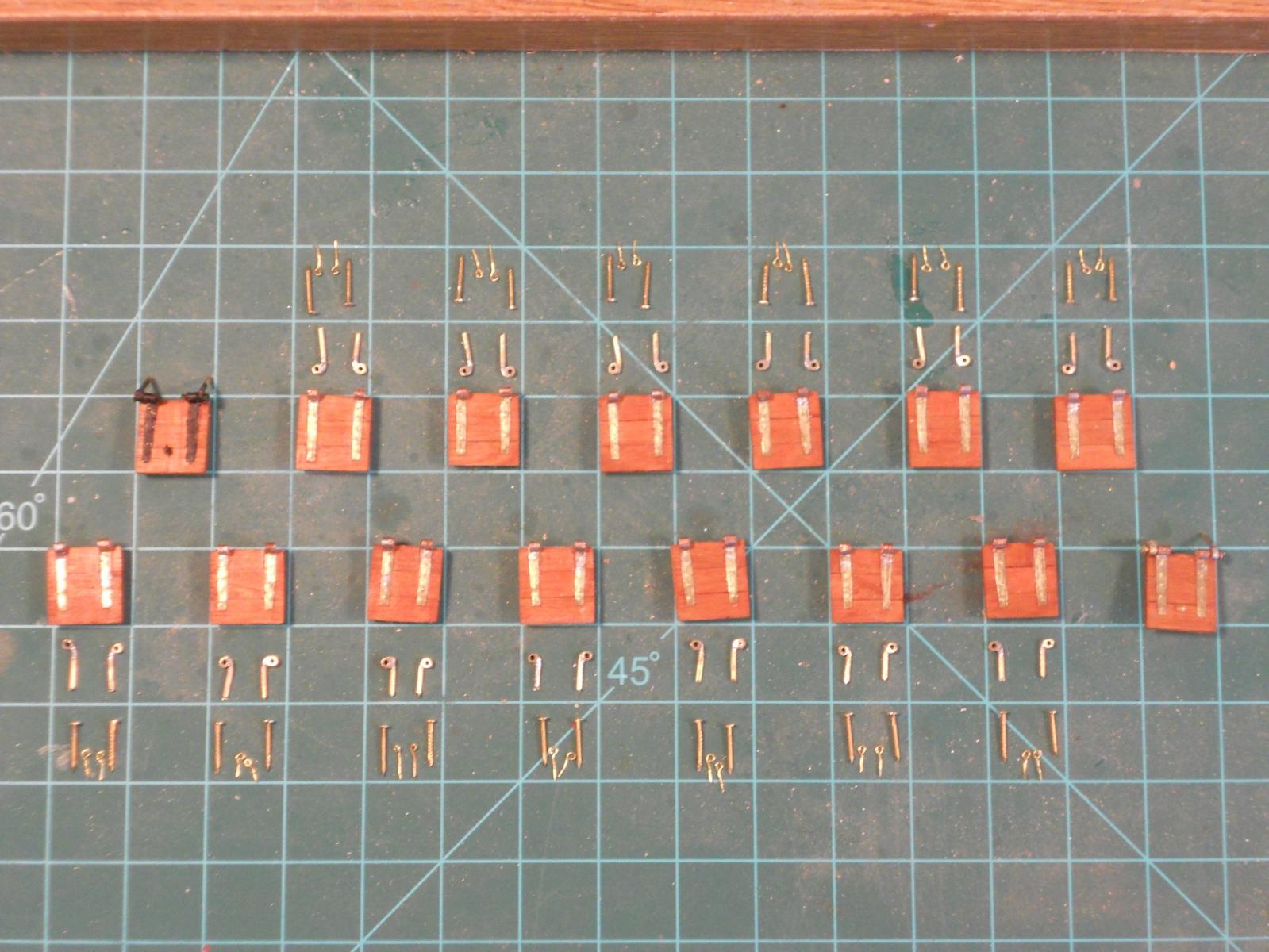
Well, the Admiral and I are back from our visit with the daughter and our grandson. The graduation ceremony was awesome, so gad to witness this fine lad achieving this milestone and now on to college. He's going to Slippery Rock, PA to study for Physical Therapist in sports. The drive both ways was uneventful, good weather both ways an very little delays due to road work, unusual. I did manage to make a few dozen eye bolts for the gunport lids while in PA but had to wait with working on the model when we got back due to much catch-up work on the yard and other things around the house. Two weeks being away from home in the Florida rainy season makes the grass grow like mad. I started last Monday with making the pintle parts of the lid hinges and finished them up for the port side this afternoon. I can hopefully finish them tomorrow, i. e. painting the "iron work" flat black and the backside red. I realize that they are not to scale but I could not locate brass tubing small enough to do the job adequately. The overall effect is satisfactory to me and that's what counts. Hmmm, now comes the task to install them to the ship All port side gunport lids with their associated hardware are lined up for their intended location. I used 1.5 mm brass tubing and 1 mm brass rod for the pintle part with the tubing filed to 1 mm wide, which was soldered to the tubing. I first soldered the brass rod to a length of tubing and then cut the tubing off next to the rod, then filed the small piece of tubing to the same size of the rod and shaped the top. The pin is from .6 mm diameter brass nails cut to the proper length and then secured in the hinge assy with CA glue on one side only so the hinge can still operate. Cheers,
-
Hello wefalck, First of all, very nice work. Love the idea of the diorama with the story. I have been following your build from the inception, first on MSW 1.0 and now again on MSW 2.0. Thank you and all other contributors for the helpful hints and web links. Reason being that I started with a botter model in a 6 inch lamp but set that aside to build my VOC ship and now also my father's sub, the O 19. This does not mean that I'm abandoning the botter in the lamp. I am also planning to build a kotter in a large scale POF and all the info on your log is extremely helpful. Thanks again and I'll continue watching your progress. Cheers,
-
Nice going my friend, beautiful work. Send from the Admiral's computer. We are now in Coraopolis, PA and enjoying the kids. I joined my grandson for a 6 mile hike this pm, really great. We'll be back in Florida next week Thursday. Cheers,
-
Hello Edson and Boris, Edson, I'll be happy to help you with whatever plans I have to produce a decent model. I cannot send them via e-mail because most are just too large and scanning them in is not practical. I also cannot sell them to you but I'll make paper copies of whatever I have and mail them to you as I did for Boris. Send me your mailing address via a personal message and I'll do that as soon as I'm back home again. Right now I am at our daughter's house near Pittsburgh, PA to attend our grandson's High School graduation. We'll be going back to Florida next week Thursday and I'll put a package together for you starting the week after. These drawings are all in different scales but I hope you have enough background in ship plans to figure out how to arrive at the scale you have in mind. I had to do the same and it worked out just fine. The stats are in my intro pages and I'll also attach a note about some of the issues with different drawings you will have a problem with without an explanation. If you have any questions about any part of the build and or the boat please let me know. I have many photographs of the actual build that may aid in your understanding. I can give you also the URL where you can find and download these photos. The cost for printing is really not that much and so is the mailing, thus don't worry about payment, I do it with pleasure for a fellow sub enthousiast. My father had his hands in the O 20 as well, concerning the work quality, so there is still a connection between him via myself. A shame she went missing in 1942 with all the crew. It is surmised that she hit a mine while submerged. He also visited the Polish submarine "Orzel" when she was being build and pointed ouy a few problems to the Polish crew. Overall he liked that boat very much. Quite an interesting history about that sub. She was also lost without a trace somewhere in the North Sea. Hey Boris, good to hear from you and I hope all is going well. Thank you for your kind words, you make me blush Cheers,
-
It's almost a ship! Well, at least it's the right material, wood. It has a railing from wood and from what I can determine it must be the poop deck I feel your pain Kevin. Same here, mow the lawn. Pull weeds. Mow the lawn again and pull more weeds Rainy season in Florida, you can actually see the grass grow and weeds, weeds, weeds everywhere. Aaaarch Cheers,
-
Thanks all y'all for the likes, it's really appreciated. @ Ian, thanks for looking in and yes, she's a large model but that'll make it easier to do some detail work on the outside. @ Sjors, well, not quite WF but should I have modeled the ship yard as well Not I'll continue to fine tune the deck structure frames, been whittling at it this pm and it's coming along quite nicely. Unfortunately or fortunately, I'll have take a break for two weeks. Just to let all yuns know that the Admiral and I will be driving up to Pittsburgh, PA next Tuesday morning at oh dark thirty. We are attending our grandson's High School graduation. It's 900 miles and it'll take us 13 hours, about, depending on traffic and road construction. I may not post any new stuff but will be visiting MSW to look at what all yuns are doing. I'm also going to drive to Cleveland with the grandson to visit the USS Cod that is docked there. That's the sub that rescued the crew of my father's sub, the O 19, when it ran on Ladd Reef in the South China Sea in July 1945. I'm exited and will chat with the curator and get the grand tour. Many pics will be taken, for sure. Cheers to all and keep modeling,
-
Thanks again fellows for all the likes, I do appreciate it very much. @ Sjors, af shucks, you make me blush but -- - - - I love the compliments Just to let all yuns know that the Admiral and I will be driving up to Pittsburgh, PA next Tuesday morning at oh dark thirty. We are attending our grandson's High School graduation. It's 900 miles and it'll take us 13 hours, about, depending on traffic and road construction. I may not post any new stuff but will be visiting MSW to look at what all yuns are doing. I'm also going to drive to Cleveland with the grandson next week to visit the USS Cod that is docked there. That's the sub that rescued the crew of my father's sub, the O 19, when it ran on Ladd Reef in the South China Sea in July 1945. I'm exited and will chat with the curator and get the grand tour. Many pics will be taken, for sure. Cheers to all and keep modeling.
-
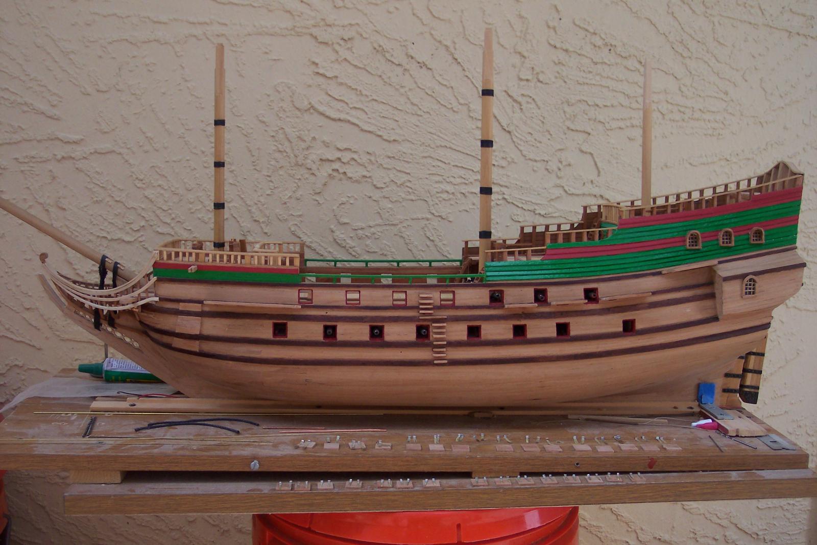
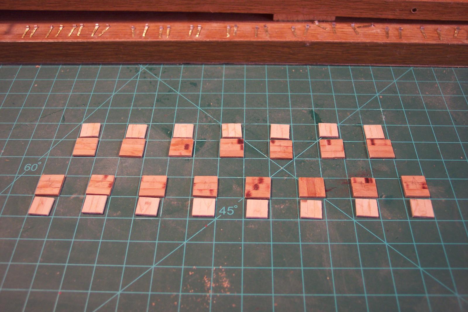
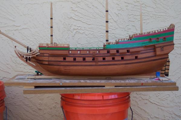
Thank you all for the "likes," it's really appreciated ! @ Sjors, yes, mine are also 12 X 12 mm on the outside part and 10 X 10 mm on the inside part. Well, here is a picture of the ship with Danish oil, lightly stained with a little cherry, enhancing the slightly bleached cherry to a more lustrous glow, at least that was the intend She begins to look like my avatar slightly aged, like me. Sure hope all yuns approve. Danish oiled port-side with a touch of cherry stain. Cheers,
-
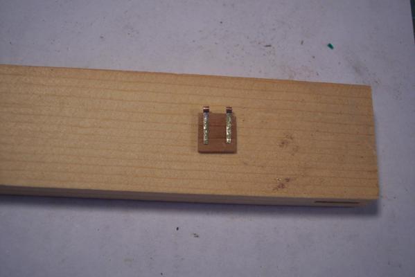
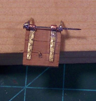
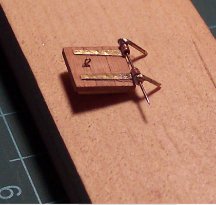
Hello folks, This post was supposed to have been placed last night but I guess I missed clicking on the "Add Reply" button. Stuff happens when you get old @ Daniel, Yes, these eye bolts are getting tiny and with another tool I was contemplating of fabricating I could reduce the size a little more but I think this small enough as the pics will show. @ Mark, tiny yes but it aint Tim I oiled the hull this morning with some stain thrown in. I kinda like the hull a little darker, simulate some weathering. @ Anthony, hmmmm, I checked the Yellow pages for Gnomes and Gnomettes but there aren't any here in palm Coast, Florida. It just so happened that I could have used one or two because little old doufus me accidentally knocked my little hold jar with 6 completed eye bolts from the work bench. Naturally they scattered all over the floor but I was able to retrieve 4 of these little buggers. No problem though, it takes me only 10 minutes to make one. @ Sjors, thanks for your kind words and I keep track of your build too my friend, with all the friendly banter that goes with it. What are the measurements of your gunport lids? I finished one gunport lid, except for the blackening or painting of the brass work. Here are a few pics how they looked like yesterday. I decided to trim some off one of the hinge bolts after seeing these pics. a straight-on view of the completed lid. The sewing pin is temporary, I plan on using some very small brass nails. Looking at this close-up the hinge bolt on the left needs a little trimming, which was done this morning. I also used the brass nails for hinge pins and CA'd the ends to keep them from sliding out. Pics with the blackened hardware will be coming soon. a side view. Yes, I dressed it up a little. Cheers,
-
Thanks for checking in John, and yes, steady as she goes. Hey, is that a nautical term? Now that the frames are pinned and don't fall off when you touch them, I was able to clamp a few 2 X 5 mm slats to them to check the form and flow. Overall it looks okay but, as I mentioned before, most are in need of some trimming, as expected. It's not much but at this stage it's crucial to make the shape conform to the drawings. I didn't take any pics of how I rigged it for the check, perhaps another day. Cheers,
-
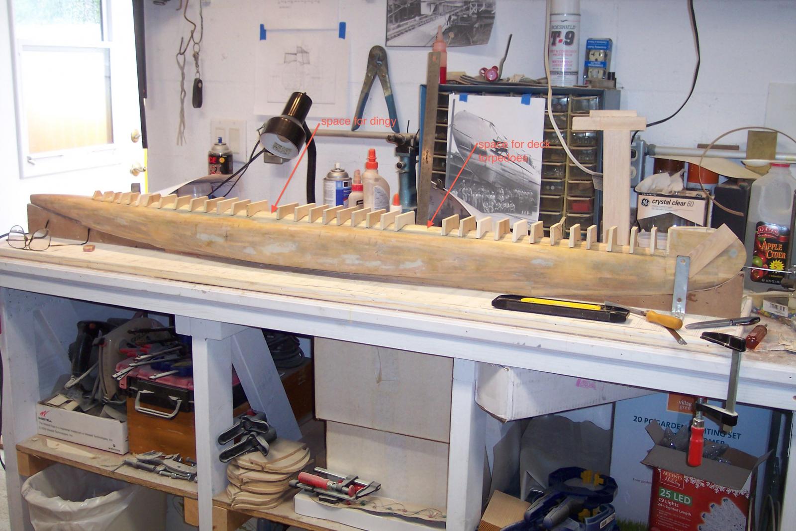
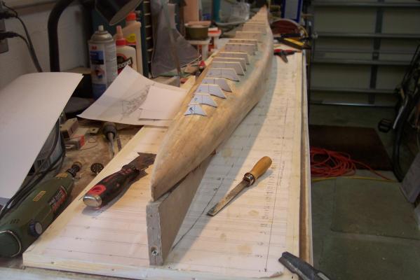
Hello all, I have added a few more deck bulkhead frames using the original drawings from the Dutch Archive as I did with the first batch. They are close to being correct but are obviously in need of adjustments. To make it easier to determine where to add and where to take away some wood I have pinned then all to the hull with one toothpick in the center. Once I am satisfied I'll cut 4 X 4 mm slots in them at all corners and in the centers for added stiffness an support for the 1 mm plywood cover. Here is a photo of de current condition. As you can see there are two gaps between the frames. The forward one is where the deck torpedoes will be placed. The aft one is where the dingy is normally located. Cheers,
-
Hoi Freek, The plan for the "con" (conning tower) is to build that separate and place it on top of the deck structure. The place for the deck tubes is already marked out on the hull and will be an open space between two bulkhead type frames. The doors will be shown open with the tubes turned on an angle, not quite looking outside the boot. That section will get some extra reinforcing for the deck itself. Fred also send be a few pics of these tubes he made, good enough as a guide and with the photos i have from the build at Wilton Fyenoord I should be able to come up with a believable set. Also the place for the dingy or jol as Fred calls it, will be a small open space behind the con with the required deck plates. The idea is to have that open with the cover plates loose and on deck and the dingy in a sling. The same plan for one of the torpedoes being loaded into the forward torpedo room and one mine being loaded. It''l be busy boat all right. I just send a message to Gino den Ridder that my model will have the teak deck slats because I want to show my model as my father knew her at the launch back in 1939 and when he sailed on her till 1941. Right now I'm fine tuning all the deck bulkhead frames, have only done four, it's slow going because there are other things I need to do around the house and also do some work on the VOC ship. Yes, I have seen Fred's models, very impressive and will visit his site more often. I even flew over his house via Google Earth, nice little town he lives in. A shame that he doing away with all the drawings he has. I suggested to store them on a DVD if possible. They are difficult to come buy Thanks for checking in and thinking of me and your suggestions and reminders, really appreciated! Cheers,
-
Hoi Sjors, Looking very good my friend, lovely work. Cheers,
-
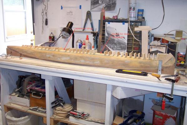
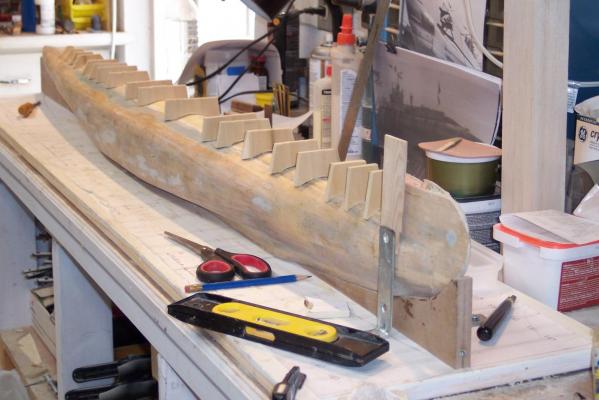
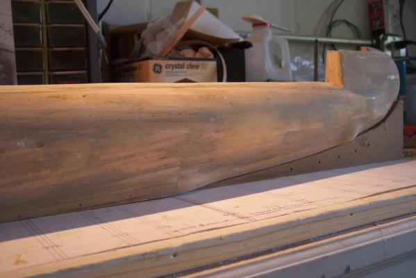
Hello all, Well, I drew up a bunch of frames for the deck structure and cut them out and glued them to a 1/4 inch poplar board. Then I proceeded to cut them all out and started to final fit them to the hull. I also thank Freek for Fred Huygen's website and I was able to get in touch with him. I asked him if he has any drawings for the little dingy and lo and behold he just happen to have the lines drawings and the measurements. Now it's just a matter of translating all that in a wooden model. That in itself will be a challenge because of the size, tiny. Okay, here are two pics of the hull with most of the deck frames temporarily placed on top of the hull at their proper locations. I need to make about a dozen more though. So far it's looking okay. The deck frame bulkheads are temporarily placed on top of the hull looking from the stern. The deck frame bulkheads are temporarily placed on top of the hull looking from the bow. That piece of wood between the steel angle and the hull is place the hull at right angles to the build board. Cheers,
-
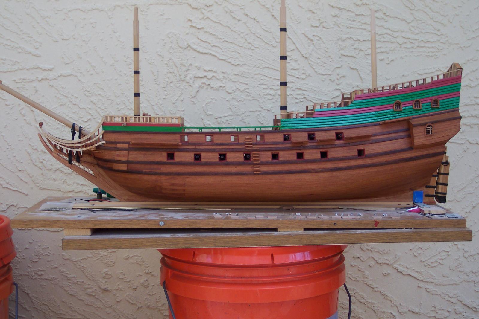
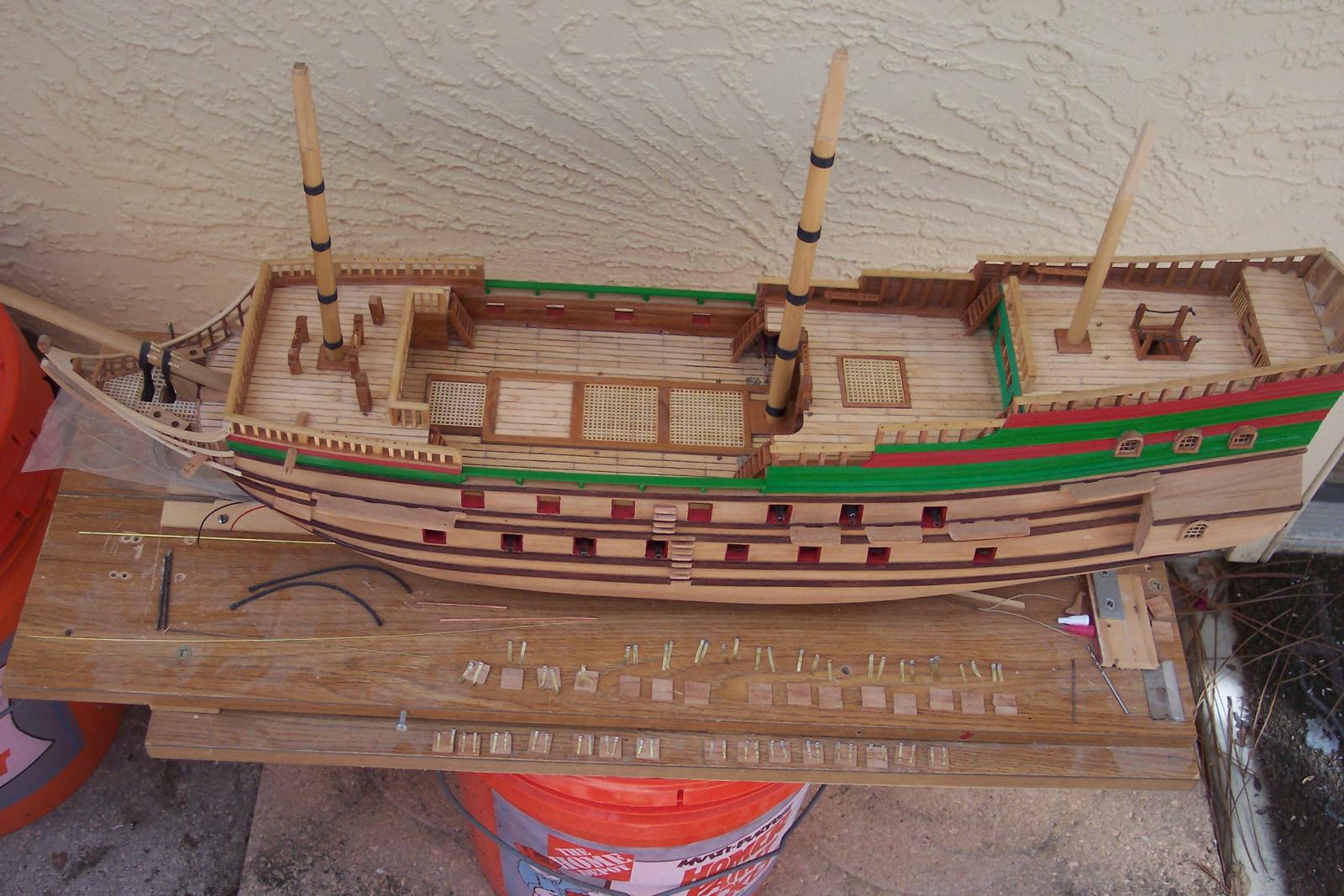
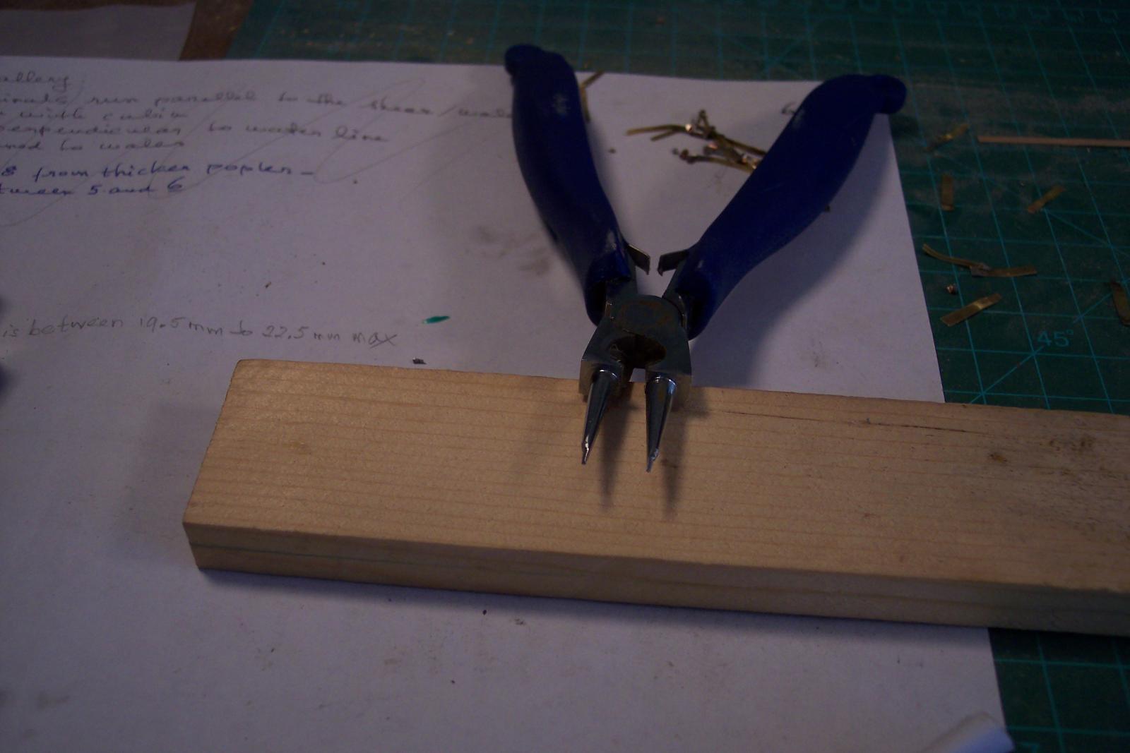
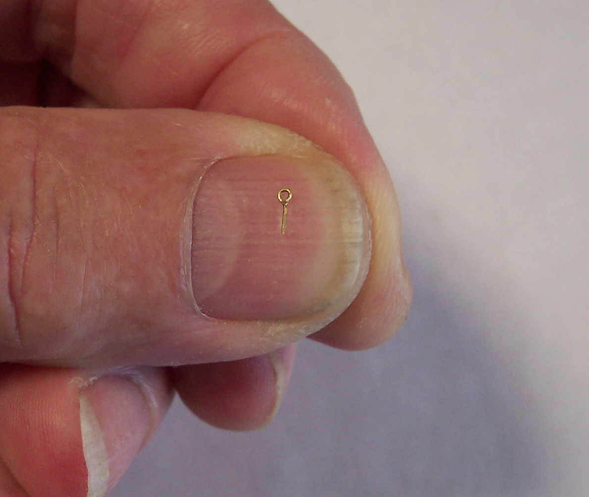
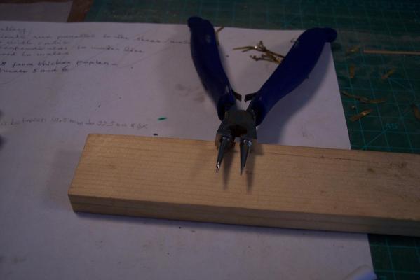
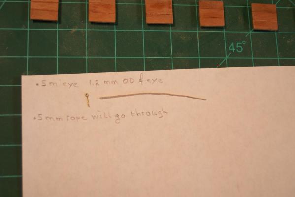
Hello all, Well, I have been able to do some more work on the VOC ship, not much mind you but every little thing counts. @ Sjors, I do too my friend. I put 3X magnifiers over my trifocals, which make it a 4 X magnification on the bottom reading part. I learned that just two days ago when I went to my eye doctor for my yearly checkup. I'm getting new glasses, not that my eyes have changed but I need more on the reading part. The distance part will be made smaller because I actually don't need them, that's close to 20 - 20. Another $ 375.00 ouch. @ Andrieke, well, with the glasses and magnifiers as explained above and my thin fingers I seem to manage quite well. I also modded my other pair of needle nose pliers by grinding and filing the tips down to .75 mm. I dare not go smaller in fear of breaking the tips off. Works like a charm and am happy with it. I thought to take a few pics of the ship this morning to show the current status. I mentioned before that I painted the gun ports and the waist deck railings, so below are the pics. How do yuns like the green railing for the waist? I also glued the back planking of the gunport lids to the front and am competing with Sjors playing checkers I may cement the hinge brackets to them tomorrow with CA. There is also a photo of my modded needle nose plier and another eye bolt for the gunport lids. This time I used a smaller diameter brass wire of .3 mm. Any thinner may be too flimsy. This is as the VOC ship "Surabaya" looks like as of may 30, 2013. Ready for the Danish oil, yes? A seagull's view of the ship with some of the parts i'm working on. I had to lay the parts out as they are to be affixed to the ship. Each one is custom fit. Here the inner planking is glued and clamped. I just did the port side. The clamps are removed for the final dressing and painting. Then the hinge brackets and finally the Danish oil. These needle nose pliers have rounded tips but at 3 mm, much too large for my purposes. So I first ground the carefully down on my electric bench grinder and then finished it off with a small file. I think that at .75 mm at the tips should be enough. The final crimping of the eye brings the eye inner diameter down to .5 mm, enough for the rope to just go through. This is the result of an eye bolt made from .3 mm brass wire. The eye is .5 mm ID and 1.2 mm OD. I think they'll look much better albeit not quite to scale yet but close enough. This is a close-up of the new style eye bolt and believe it that it's all handled with my itsy bitsy fingers, no other tools I have to really stay over my work area, loosing this one to the floor is goodbye forever. Cheers,


-
Hello Sherry, I agree with Steve, the captain's cabin should be the one with the open balcony so he and his sweetie can sit there in their rocking chairs and sip mint juleps and munch popcorn Ref the deck colors, please don't make too dark, even honey maple can make it too dark for decks. I like to see some contrast too and with the walnut for the hull planking that should look great. Cheers,
-
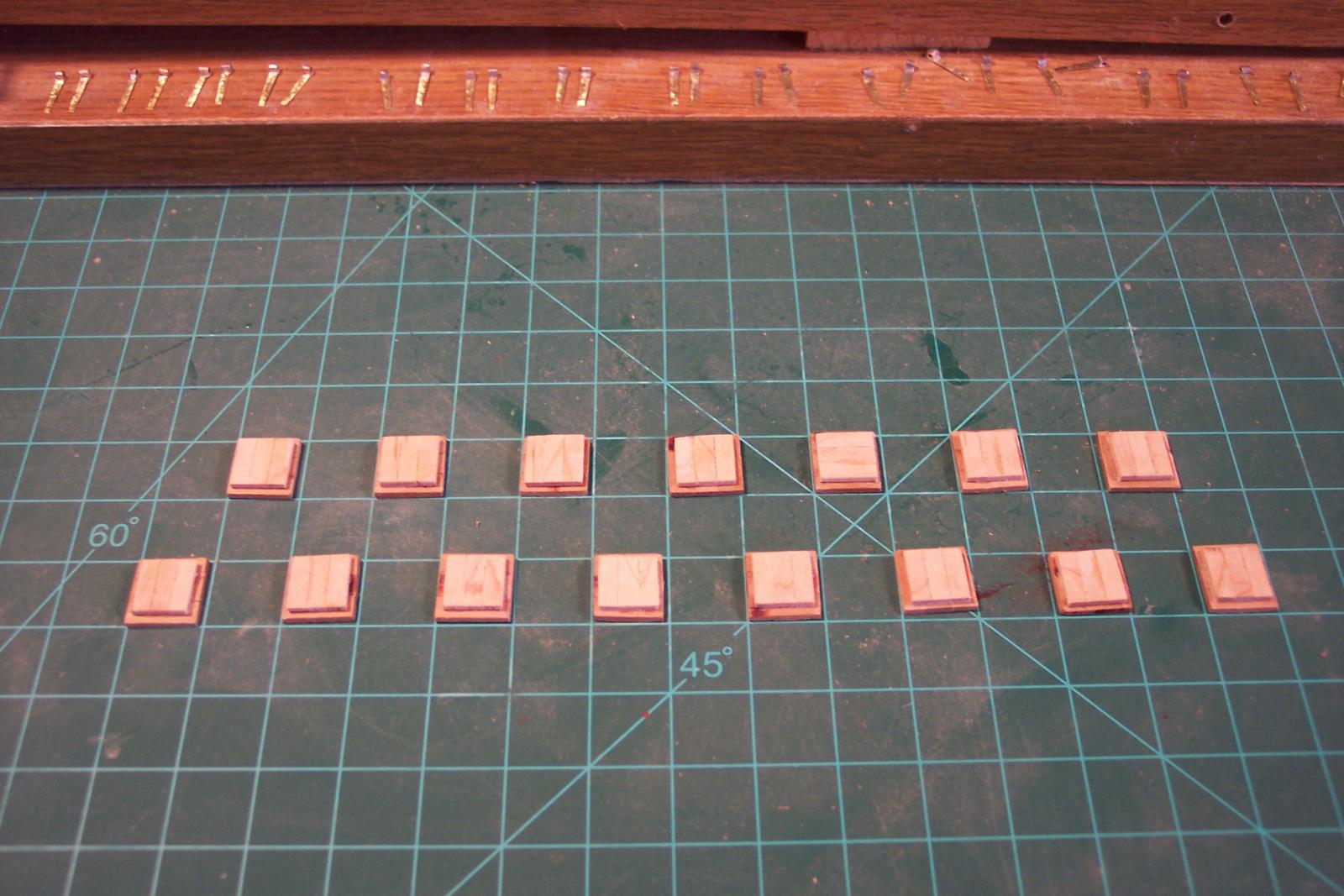
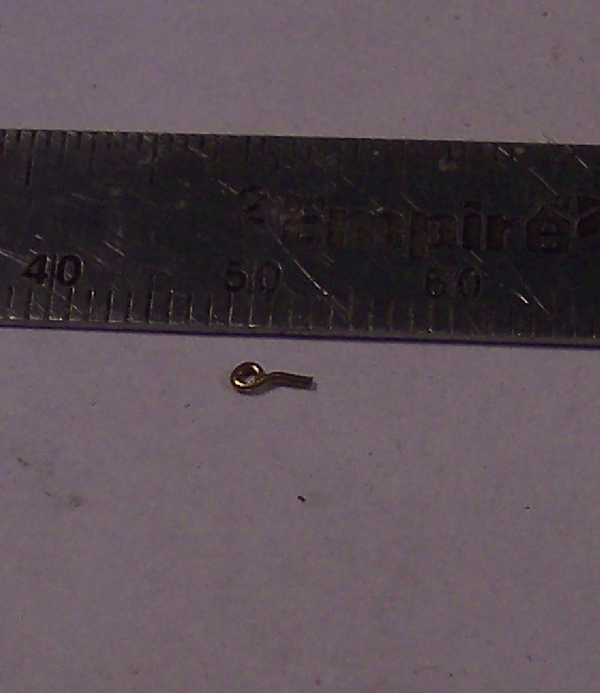
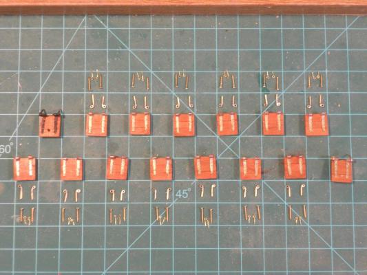
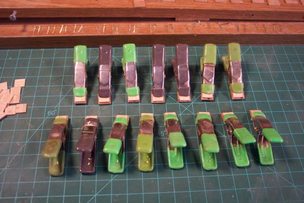
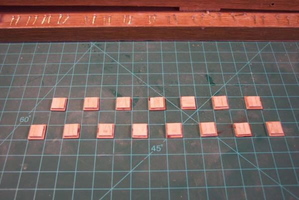
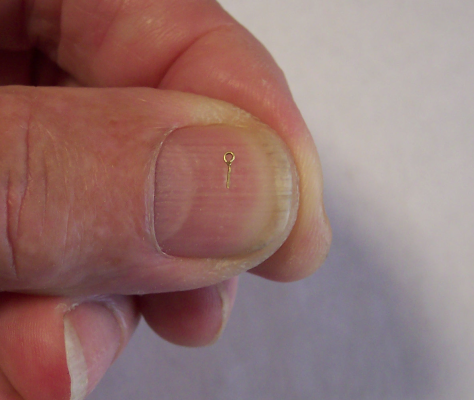
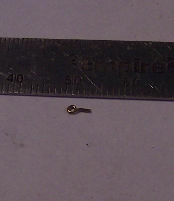
G'day everyone, I have completed 16 pair of gunport lid hinge brackets and am ready glue them on the lids. That's enough for one side of the ship. I also painted all the gunport openings red and the waist railing green to match the forecastle and aft part of the ship. I'm contemplating to start putting Danish oil on the hull from above the lower wale only before mounting the gunport lids. Who knows, I may just do the entire hull and get it over with. I also started to make the gunport lid rope eye bolts and used .5 mm brass wire. It's still too large to my liking but the problem is my needle nose pliers. This is about the smallest I can make them with the modified pliers I have. I already ground the tips down and am afraid that if I grind the tips further that they'll brake off. The opening is the right size for a sewing pin that I plan to use for hinge pin. Perhaps once they are mounted to the lids they may not look too big, I'll have to experiment some. I'll try with thinner brass wire and use my other round tipped needle nose pliers with the tips ground down to 1 mm. Here is a photo of one of them. The outside diameter of the eye is actually only 2 mm and the bolt part is also 2 mm. A visual representation of the size, it's not the best one out of the 6 I already made but it's okay for demo purposes. Cheers,
-
@ Andrieke and John (Lad), thanks guys. This morning I found out that the top center on the starboard side of the hull has few small dips between bulkheads that I didn't notice before. It's too much to ignore and have to but some Bondo on. It's "only" a few thou (inches) but I'm afraid it'll show later on. It's no big deal but here you think that after all the checking and double checking with a 3 foot straightedge that everything is okay, and here you have some irregularities. @ Jan (Amateur), yes indeed! Thanks for thinking of me, appreciate it. I have pulled all of them off and saved in my O 19 file. I also received many pics from Gino den Ridder, assistant curator of USS Cod in Cleveland, OH. The photos he send me are a lot better quality and I'm using them for detail work. Without spending a fortune I like to have drawings of the little dingy the subs carried below deck. I have a few pics that show the dingy and I could draw up scale drawings that may result in an acceptable model but there is nothing like being accurate rather then close enough "Close enough" is only good in government work Cheers y'all,
-
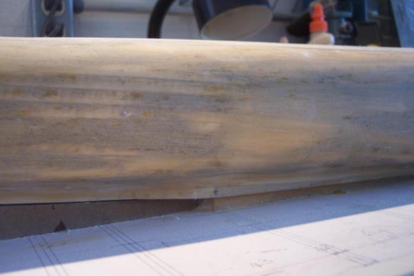
Hello all, After the second coat of epoxy resin had cured enough I started the sanding process. It's looking much better but I still have a few low spots. I am contemplating of putting on a third coat of epoxy resin but will do that in two stages. First just in the low areas and let that cure and then follow up with a full coat. Then sanding again and see where we'er at. Another option is to use some Bondo. I bought a can last Friday. I remember from running my aircraft repair business that Bondo made a one-part filler for small dents or divots. I'll go and visit the auto part store tomorrow to ask what they have. If they have what I want then I can return the two-part Bondo, if not then I'll have to experiment mixing a small batch. Here are a few close-ups of the hull as she sits right now. You should be able to see the low spots, where it's still shiny. This is a close-up of the aft section of the hull. The shiny spots are the low spots. Yes, the epoxy resin is translucent and you can see through it to the wood and wood filler in spots, even after sanding. A close-up of the forward section. Cheers,
-
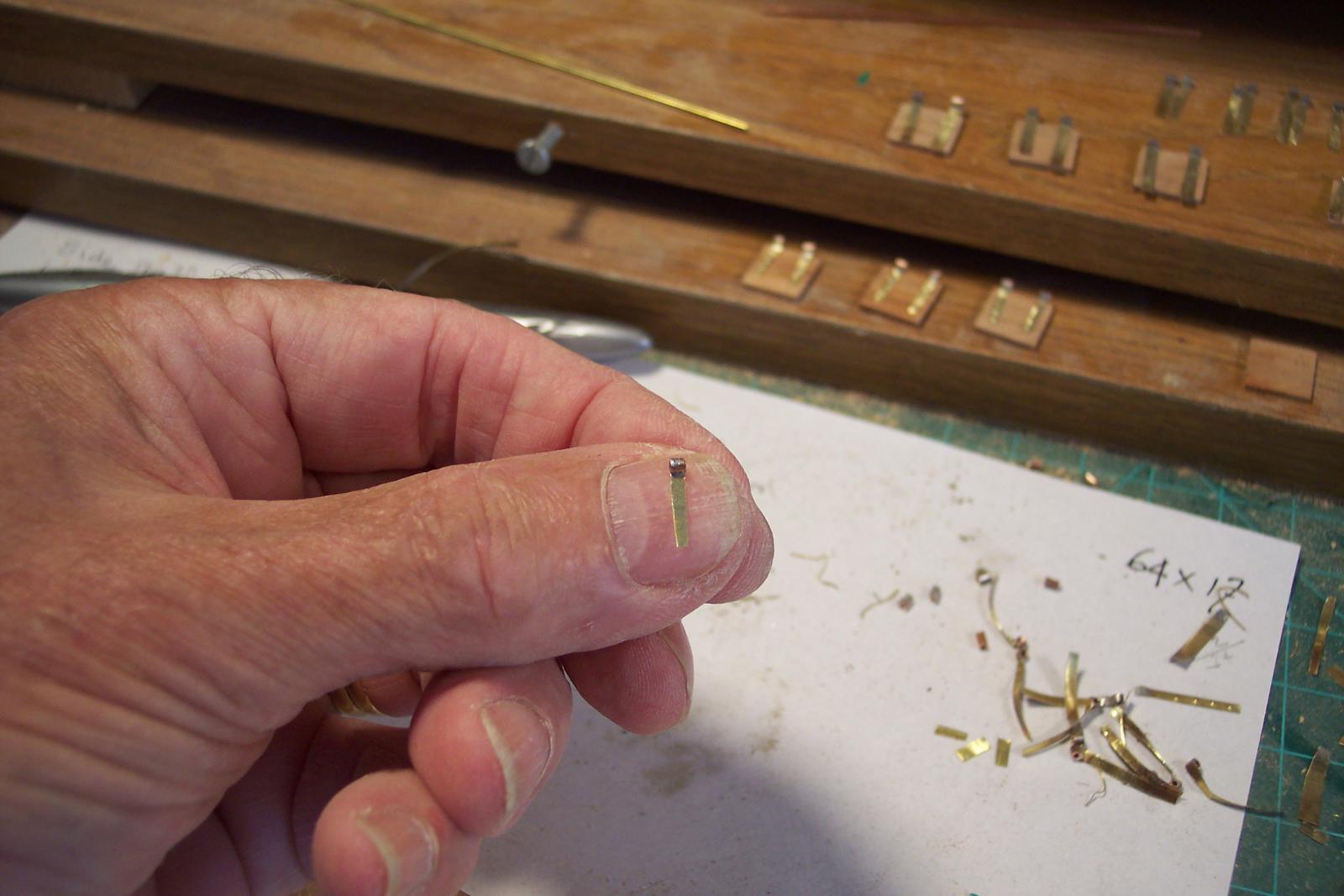
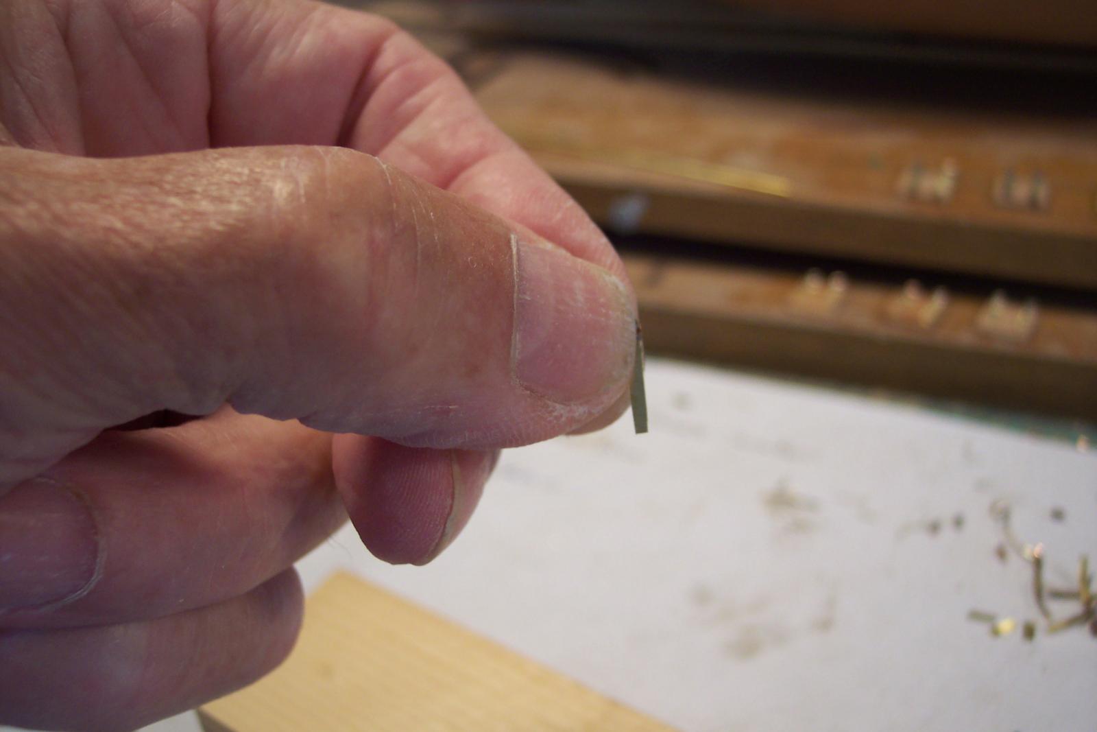
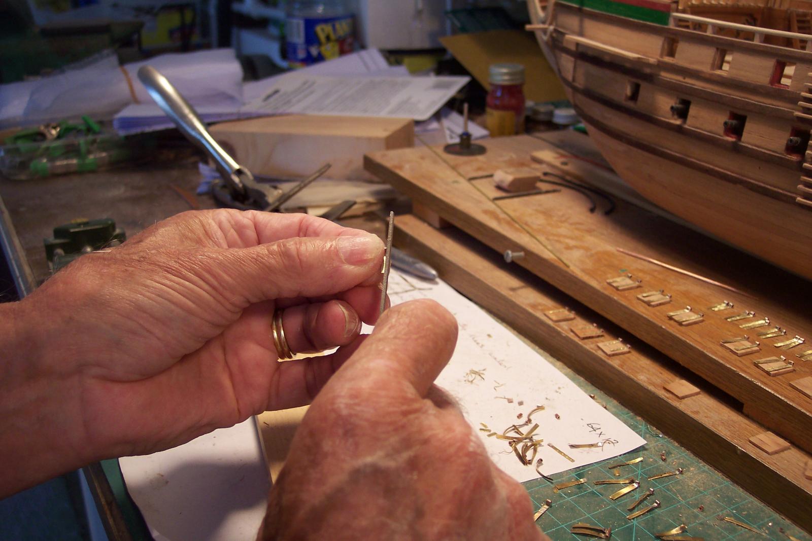
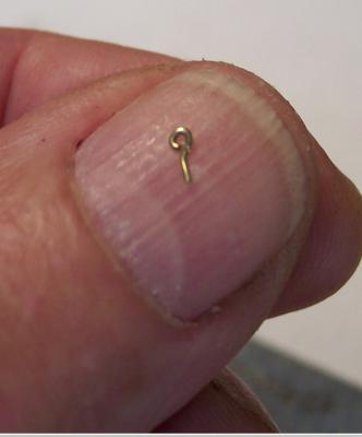
Hi Anthony, well, the thought of a crock head did cross my mind some time ago but then again the name of the ship is a combo of two names, the crock and the shark. I also thought about small sculptures of crocks and sharks at the midsection railings instead of the traditional dolphins. The counter is getting a sculpture of the crock and the shark in battle and that should be enough. I kinda like the lion at the bow though. @ Runner 3, is that you Bob? Thanks for dropping in but the build is slowed down a bit due to more attention to the O 19 sub build. But I decided to split my time between the two, so I should make some progress with the VOC ship. Well, I have done some more work on the gunport hinges and can now also show how I handle these small critters. In a previous post I mentioned to Sjors that I hold them in my left hand to file them down. Below are a few pics that'll show you that I was not kidding. The trick is that I let the edge of the file ride across my index finger. It does'n take any skin off and is a good guide. They are small alright and do jump out of my hand quite often. An indication of size. Then consider that I have long, slender hands with rather slender fingers. This is how I hold the little buggers. This is a close-up the Admiral took of me busy filing the hinge. Cheers,


-
Hey Sjors, the port lids are 10 X 10 mm and the hinges are just over 1 mm wide at the bottom with about 1 1/2 mm copper tube on top. I may have to file them down a tad yet. Yeah, they are small but once you get going on them it goes rather fast. But then again fast is relative. Next Christmas eh? Well, I hope not but the sub seems to take priority right now so you may be right @ Druxey, thanks for your input and yes, I think it'll look better and closer to scale. Cheers,
-
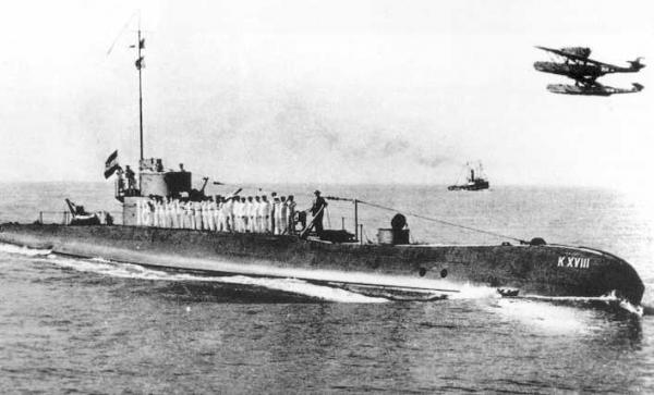
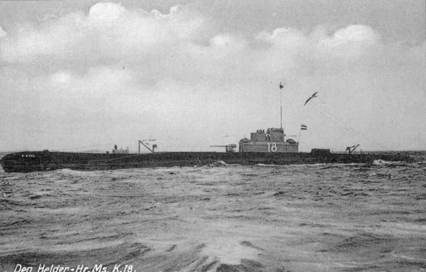
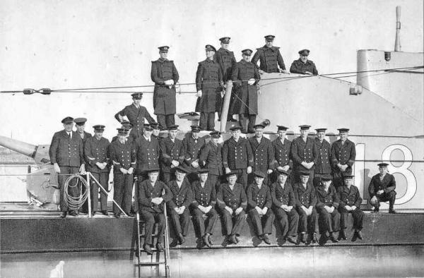
Thank you very much fellows for visiting and your comments. @ Remco, well, after using epoxy resin in my aircraft repair facility It's like old hat for me. I added an second coat and am in the process of sanding it down. I may need a third coat before I can ascertain whether I'll have use some bondo. @ Mark T, yes, she'll stiffen up some, which is okay. @ Popeye, she's coming along okay, slowly but surely. @ Sjors, it's raining in Holland??? No, tell me it isn't so Actually, I lost my gills some time ago No prob with the pics, I'd rather see sunshine then rainy pics @ Freeks, thanks for visiting. My model is static though but I enjoyed your video, nice job. I understand from Gino den Ridder that the side launch torpedoes were a bear to calculate for a good shot. It so happens that my father also served on the K XVIII after she arrived in the DEI. He had a long career in the KM (Royal Navy) but I don't know on what other boats he served. He mustered on in the early twenties. Below are a few pics of the K XVIII, he appears on the one with the crew, he is standing behind the guy who is sitting on the ladder. @ Robin, thank you for looking in and your kind words. Yes, there is indeed a family connection, that's what makes this model special. @ Carl, missed you my friend, glad you are back in circulation. Actually,the shine is only temporary because after sanding the epoxy resin she'll be dull and then she'll be covered with paper to simulate the steel plating. Then she'll be painted in the same colors as my father knew her. This was during a fleet review near Surabaya, Java. Unknown date. A calendar picture with the entire crew. My father is standing behind the man sitting on the ladder. Cheers,
-
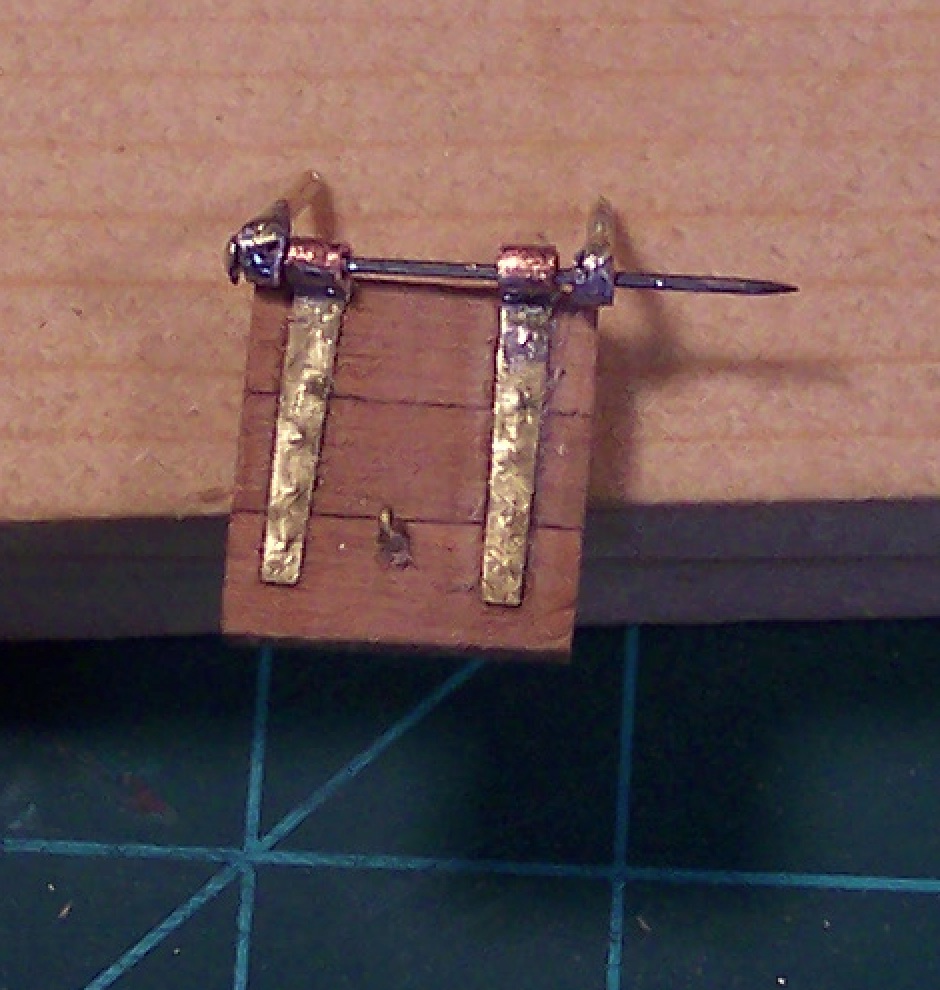
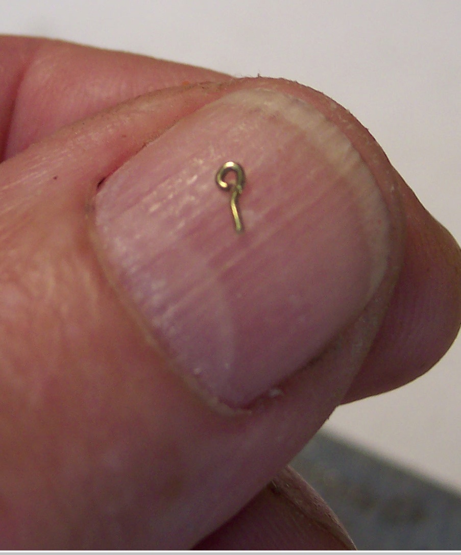
Hi Sjors, Yup, much too big. At a scale of 1:80 they would be quite large and heavy. So, I cut then down a little, which was kinda tedious to say the least. I used a pair of large sewing scissors to cut a sliver off and then a small file to file the copper tubing to fit. I had to do all this while holding that little thingy between my thumb and index finger of my left hand. Yeah, I have dainty small hands but enough grip to crush your's I'll have Gwen take a pic for yuns to believe it. She was surprised to see that I still had all my fingernails. I redid two pair of these little critters and made a picture. Looking at it I realize that I need to do some more filing. Photos are a great source for finding small imperfections. My oh my, what have I gotten myself into, 32 gunport lids, that means 64 little hinges and then the hinge brackets Okay, here is a picture of the reworked hinges. The reworked hinges laid on top of one of the gunport lids. The right one needs a little more work. Cheers,