HOLIDAY DONATION DRIVE - SUPPORT MSW - DO YOUR PART TO KEEP THIS GREAT FORUM GOING! (Only 36 donations so far out of 49,000 members - C'mon guys!)
×


Matle
-
Posts
123 -
Joined
-
Last visited
Content Type
Profiles
Forums
Gallery
Events
Everything posted by Matle
-
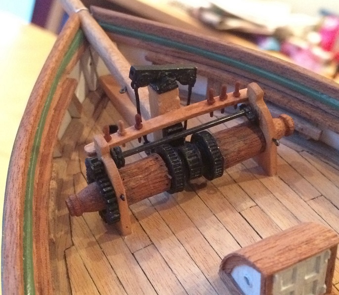
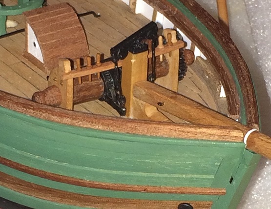
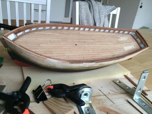
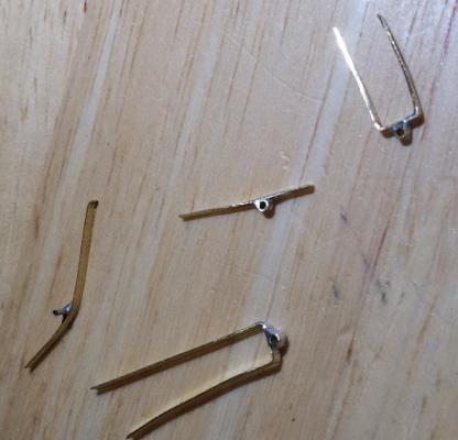
Finally had some time and spent it building the windlass. The current windlass is a replacement I suspect, and based on old photos I believe the original was either a variant of that patented by Bergqvist in the 1850s (fits in time and space as well) as seen on pp 18-19 here: http://www.sjohistoriskasamfundet.se/fn_split/fn29_a02.pdf - or something quite similar, so I based mine on that. The drum was made by glueing strips of wood on hexagonal pieces of ply, and the central ratchet wheels (or whatever they are called) were made from cable ties around dowels. A modification had been made on Gjøa, so the windlass could be operated by the in the engine by means of a messenger chain running all over the deck. The mechanism is seen on some of the images I linked. I manufactured the large cogwheel from plastic material, having no means/knowledge of doing that properly in brass. A styrene strip was fastened around a circular centre piece, and cogs were glued to it. I also installed the bowsprit, carved out of birch.
- 21 replies
-
- 6
-

-
- gjoa
- constructo
- (and 1 more)
-
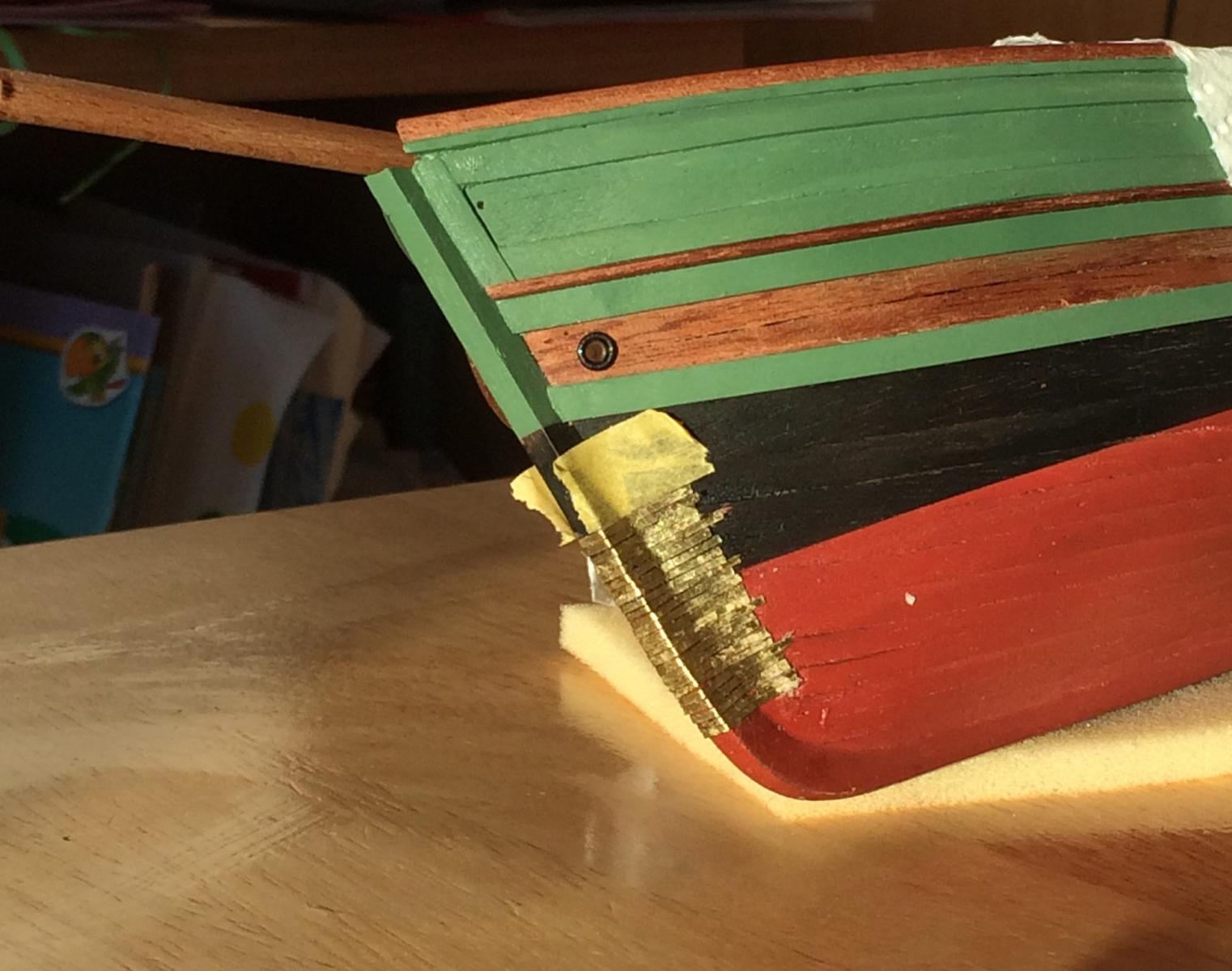
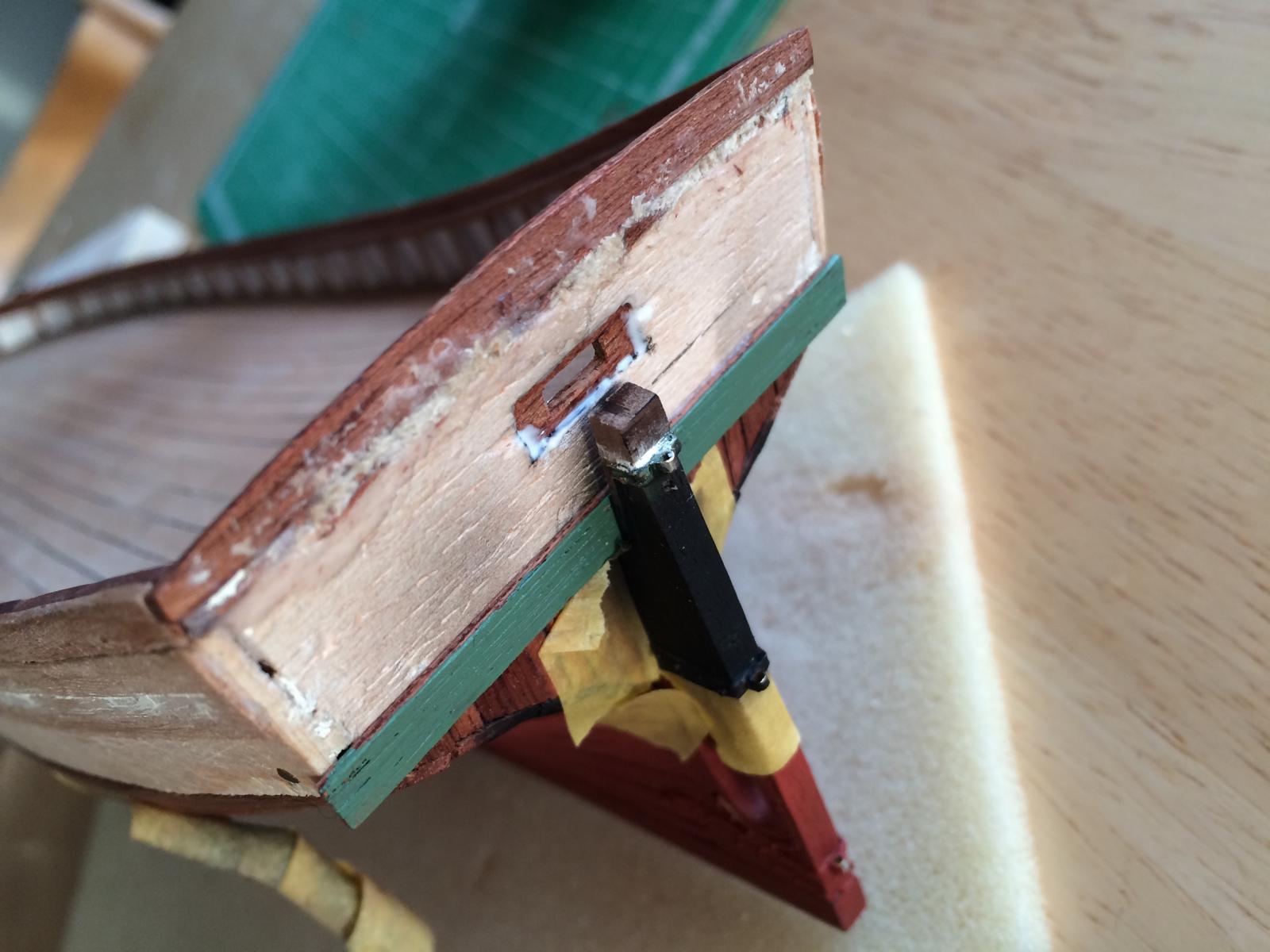
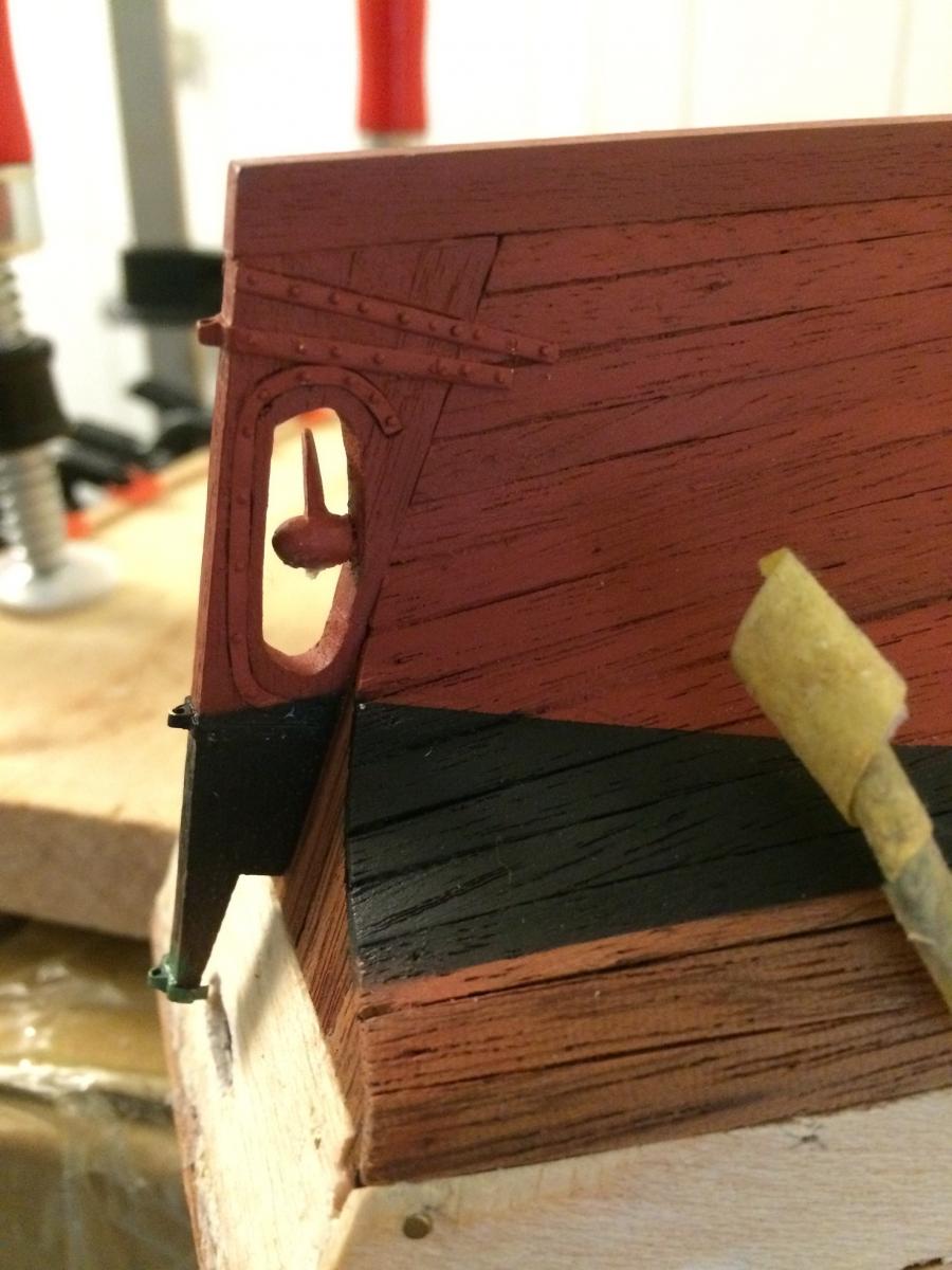
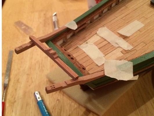
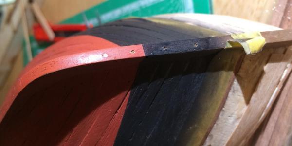
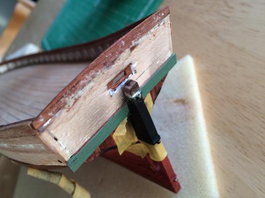
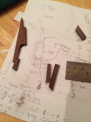
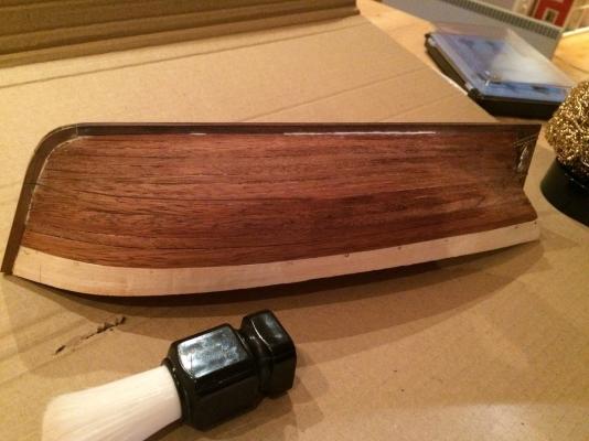
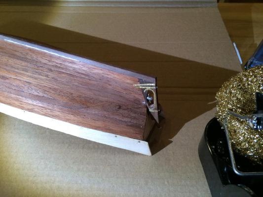
Thank you --- Just to ;mention it, I welcome all sorts of constructive criticism, on the design of the vessel itself as well as on how I build the things. Being new to the craft, I hope to improve anything that can be improved. --- Working in parallel with several parts. I had previously left out the iron reinforcements to the stem, as I had not found info on how it was done. Now, I found this excellent picture (linkie: http://digitaltmuseum.no/011014219978)which shows the bands above the waterline. They correspond pretty well to those on the MS drawings I got a few years back, with every fifth or so band longer than the rest, so I decided to go with that. In addition, the Fram seems to have had almost an identical arrangement at the time, sealing the deal. I cut brass strips and simply glued them on with epoxy, being quite apprehensive about ruining the paintjob, which I was quite happy with. As it were, the glue ended up everywhere, but once cleaned and painted over again it turned out ok. First I brush-painted the brass black, above as well as below the waterline, and followed up with a few very thin sprayed coats of appropriate paints. No shade difference between the new and the old painting can be seen, which I was mostly afraid of. The black primer also adds some shadow definition for the red part too. I also installed the stern davits, made from cherry (what a joy to cut joints in, compared to the kit supplied wood!). The sheaves are only suggested, with .4 mm holes drilled. A tricky job to get angles correct. The boom rest was installed after attaching the davits with dowels, fiddling around with the beam until all angles look square, then the davits were marked and mortices cut in-situ.I also simulated the leather protection on the boom rest with tissue paper, soaked with coloured white glue. I'm afraid the iphone is not very well suited for taking pictures of small things, but it'll have to do.
- 21 replies
-
- 4
-
-
- gjoa
- constructo
- (and 1 more)
-
On that topic Corel's Amphion is based on the yacht on plate 44 in Architectura navalis. The mentioned museum has a model based on a drawing by Chapman that is believed to be the real Amphion.
- 66 replies
-
- 3
-
-
- resolution
- hunter
- (and 2 more)
-
Many thanks for this advice, it is clear I need to study more before making this investment. The Boley in question was indeed a D-bed. I'm not sure what the bore was, but the seller wasn't either so I stayed clear. Going to keep looking for either watchmakers lathe or one of the old Austrian unimats. I'm not in a rush, so I'd rather wait for a good opportunity.
-
I'm looking for a small lathe myself, and found an ancient watchmakers lathe (Boley). Haven't decided whether to buy or not, as it lacks clamp and motor for driving. Anyone who knows if it's a reasonable idea to add a motor to run it (i.e. will as reasonable handy guy make it run reasonably well) or if I should try to find something more modern?
-
Agree, and the French takes the prize for the oddest. You can barely tell which way this thing is supposed to go (Carnot's near-sister Massena):
-
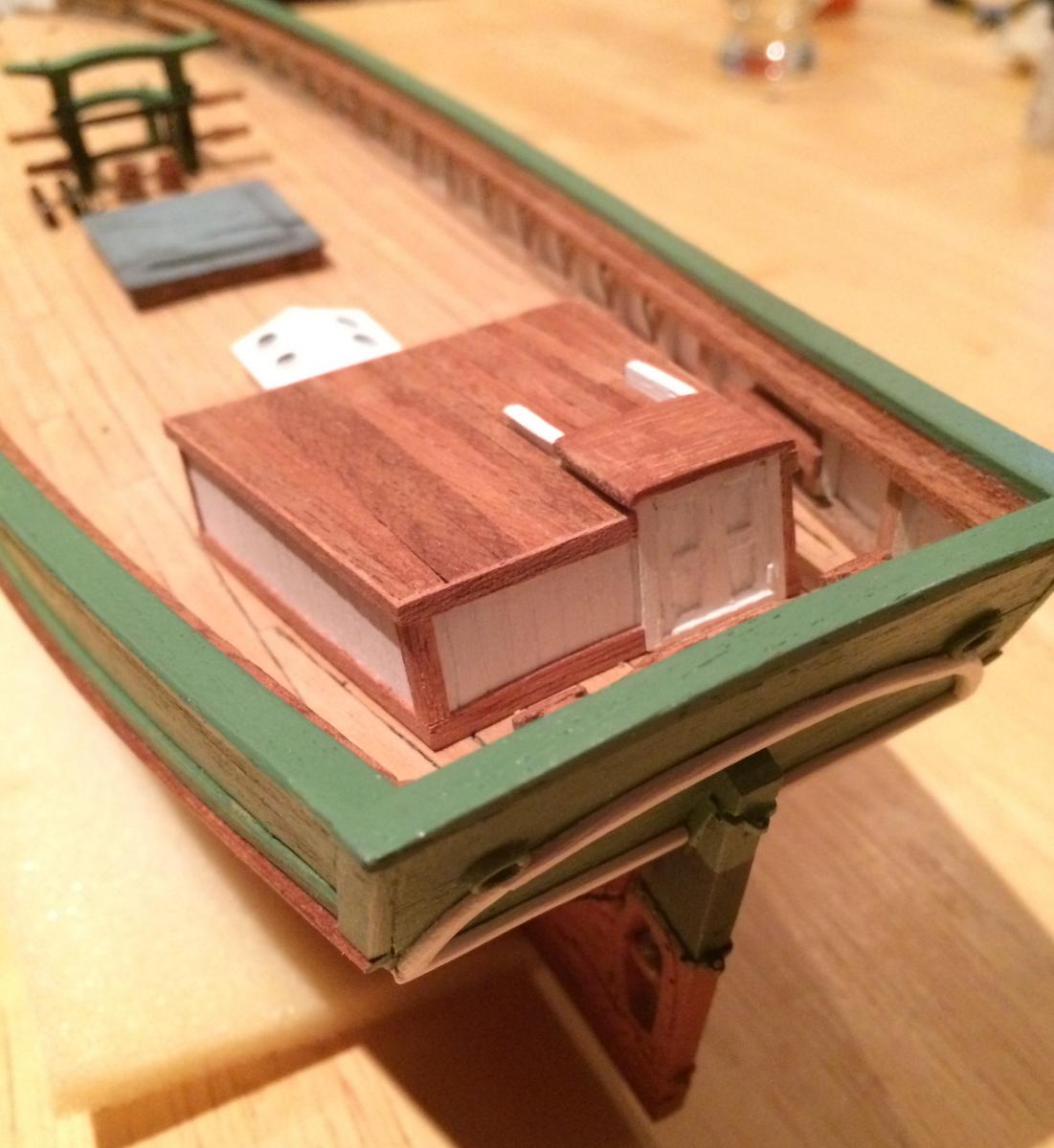
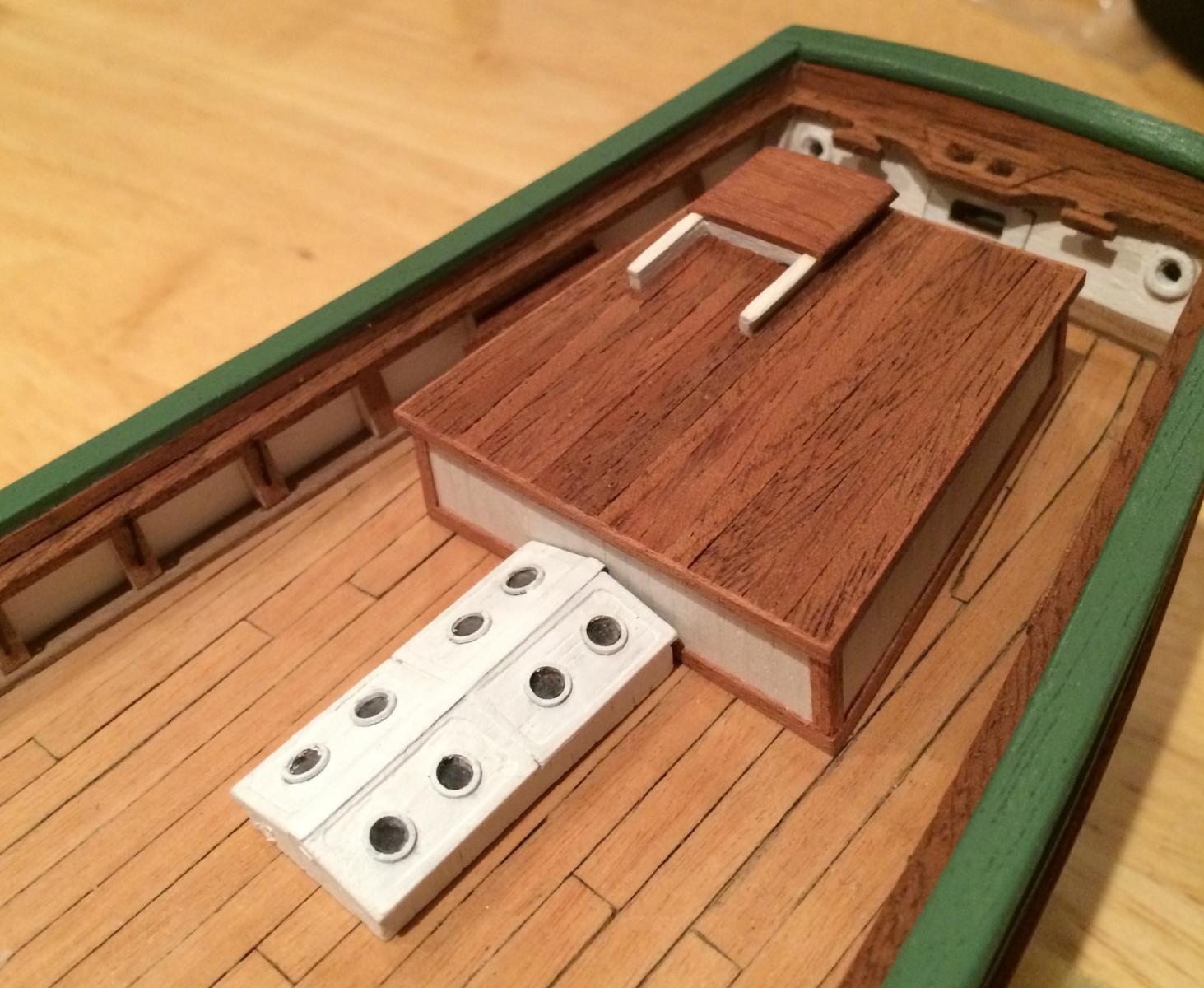
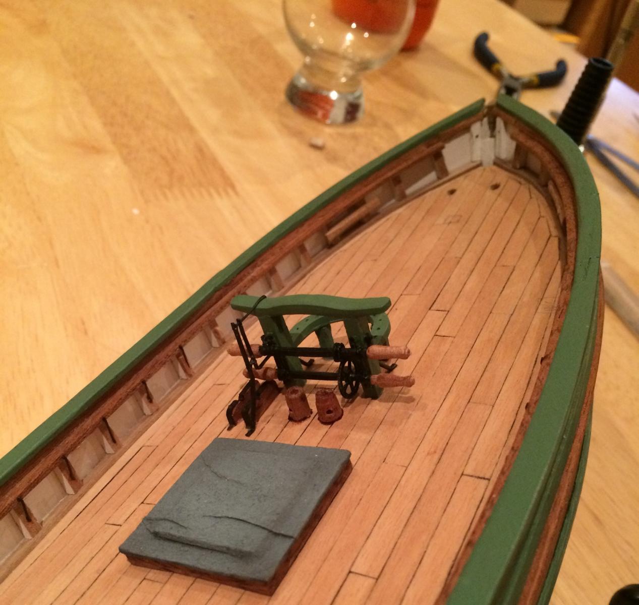
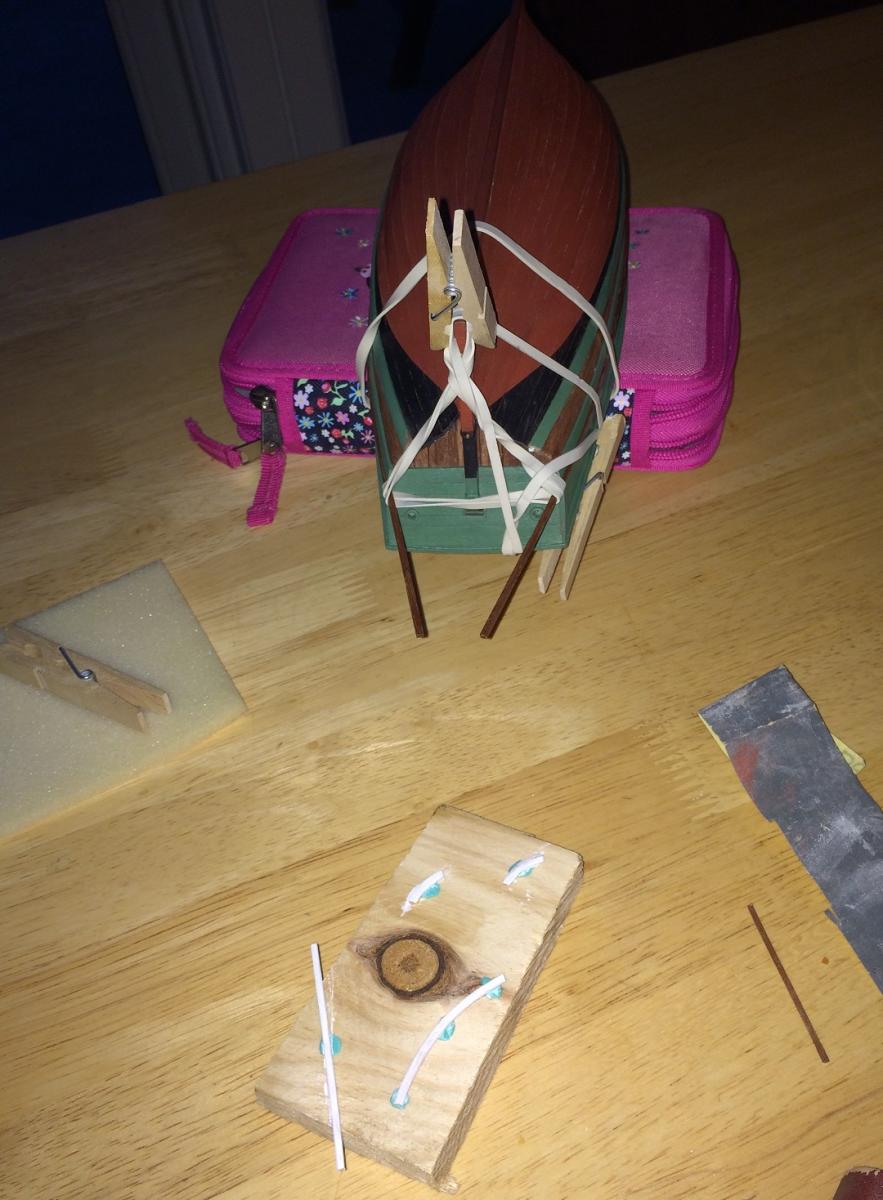
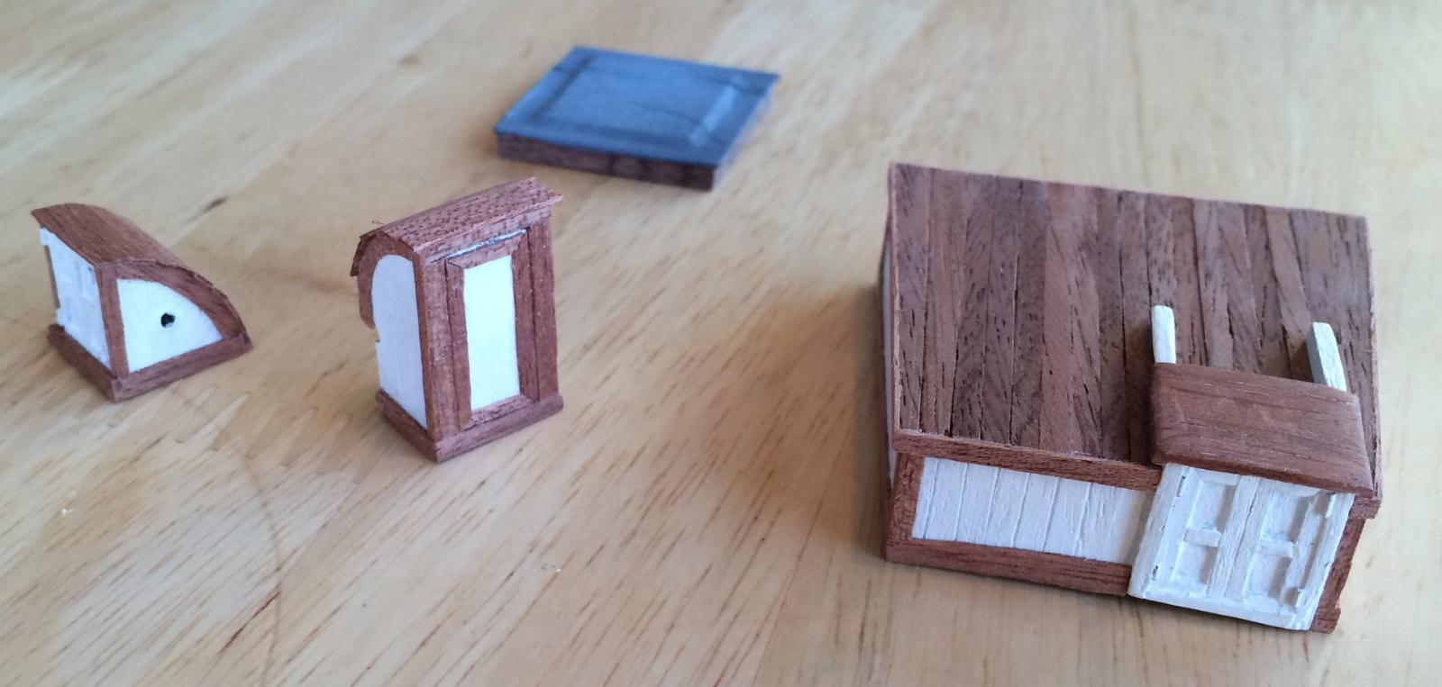
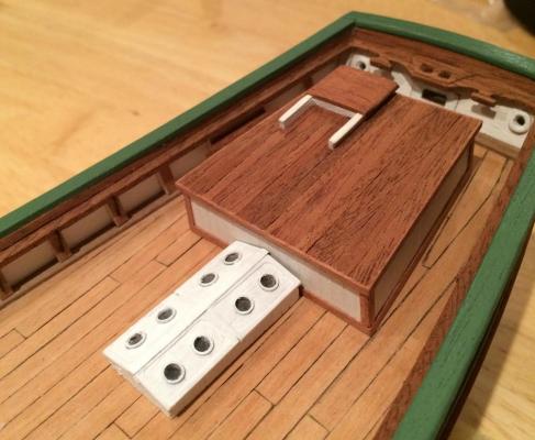
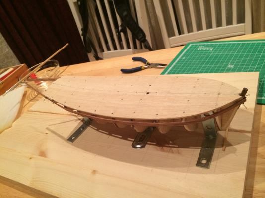
A belated thanks for the likes and a small update. Progress will continue to be slow as I'm spending a few hours weekly. I'm continuing the work on the deck furniture. A big problem is that the majority of available pictures show her in her present conditions. After the journey through the passage Gjøa spend six-seven decades in San Francisco, and beside a paint job or two, little was done to maintain her and time and souvenir-hunters slowly deteriorated her. After being returned to Norway she was restored, or rather rebuilt as much of the detail is now different. Apparently there were some reconstructing going on just prior to shipping her back, as told in this thread: .http://modelshipworld.com/index.php/topic/11776-help-identifying-some-things-on-the-bulwark-19th-century-merchant-vessel/ Almost no images show her prior to the SF stay. I try to reconstruct her from the images that exist from Golden Gate park. I found some googling around the net but am a bit skeptical on the copyrights as I believe they might be from the old MS kit instructions so I don't want to reproduce... they can be found by googling in any case. They show the ironworks - pump, winch, windlass (which seems to be different from the one currently on her) and the gears for driving the messenger chain. By the way, the chain will be able to drive the pump as well as the windlass. The winch for the rigging seems to be manual only though as I see no sprocket wheel on it. Anyway, here the current state of the rail around the mast. I have prepared the pumps as well and am working on the metal work. Similar pumps can be seen on this still sailing yachts. On Gjøa it could be driven by the engine via messenger chain and the junk on the left side is a guide for the pump handle and the wooden support for the axle with the sprocket and linkage to the pump handle. I couldn't figure out the construction of the hatch so I just covered it with tarpaulin Two shots of the house and the finished skylight. House built by veneer on ply core. Skylight portholes made with clear plastic glued in a recess and fastened with a sliced piece of brass tube of fitting size. The engine was beneath the skylight and the driving shaft will go through a hole through the forward side of it. They still need some detailing and are only doweled to the deck but the slow going is bad for motivation so I needed to see some progress. I don't like that the roof doesn't follow the deck camber but I guess that's how they did it.


- 21 replies
-
- 5
-
-
- gjoa
- constructo
- (and 1 more)
-
Hello Jay, Thanks for the article. I'm aware she's been restored on the border to rebuilt, and try to base the model on older images. Unfortunately they are very few, and on most of them Amundsen and his friends are blocking the details. Also, his account of the journey through the Passage is very interesting in itself, but offers few clues to the ship. There are plenty of pics available from her in the restored state but as you say, the details seem to differ for most of the fittings - e.g. the entire windlass seems to have been replaced. The pics I have posted here are from her time in San Francisco though, and I believe nothing has been added (apart from repaired bulwark planking as far as I can tell). Rather the other way round - for example as visitors were taking souvenirs, as indicated in the article. In short I'm trying to take the information from the San Francisco time and only use the current state if all information is lacking about that particular detail. So far only the paint job I have taken from the present, as that was supposed to be the scheme chosen by Amundsen.
-
Even if it the castles were built by the shipwrights on a military purpose vessel, they were probably of much lighter construction. The recently discovered wreck of the Mars, sunk in 1564 has a relatively preserved stern castle. She was a huge military-purpose vessel and although she was more modern, primarily an artillery ship, she still carried a castle that was built with a much lighter internal construction than the lower hull and clad with thin clinker planking as opposed to the thick carvel hull planking. Not sure how much that can be interpolated backwards in time, as Mars was a big step away from ships designed for primarily boarding towards ships designed for artillery duels, but I figure previous shipwrights would have noticed if the carracks starts flipping every other turn.
-
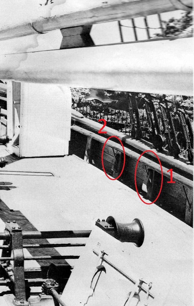
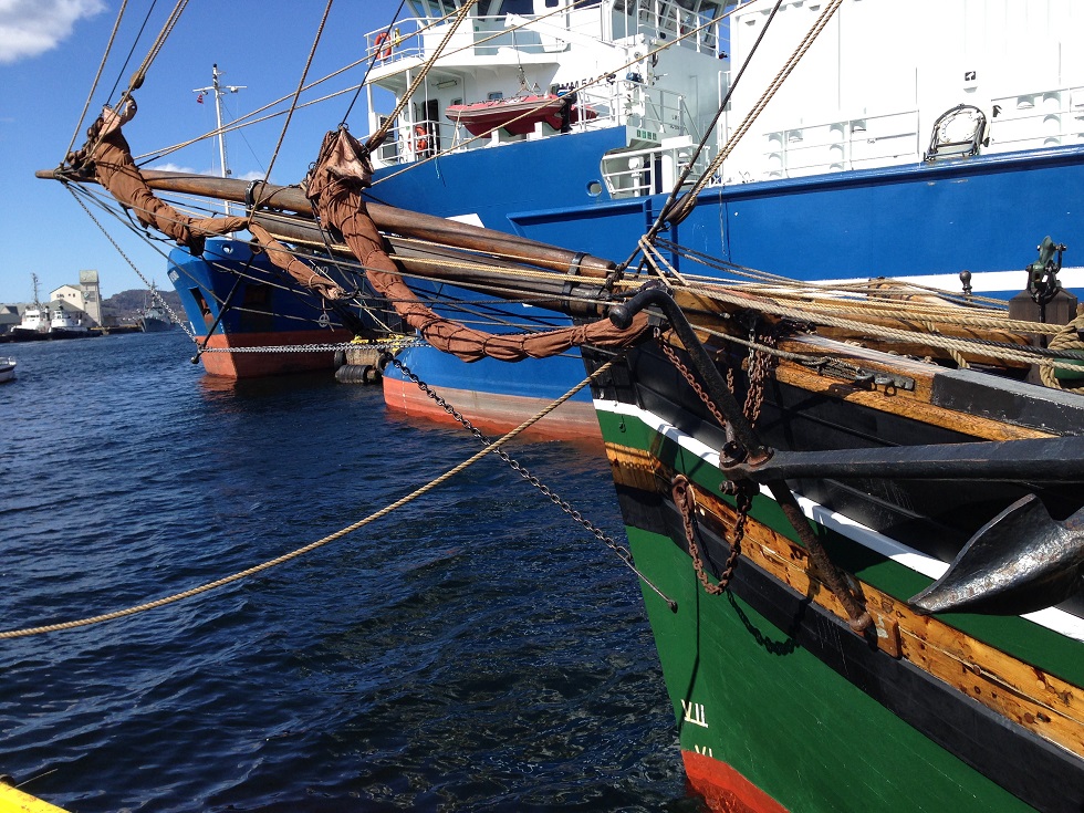
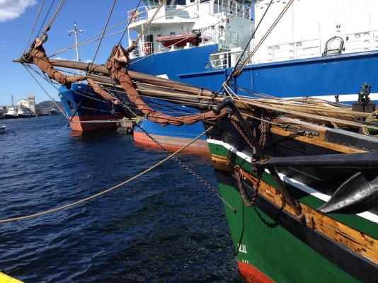
That was quick answers. Yes, there's a pin rail there, where the plans (I have two sets, none which I trust completely, but here they agree) have much of the rigging from the two square sails, plus jib halyards. What kind of rigging would need to go through these things? I imagine ropes coming at annoying angles or ropes prone to move about a lot? Or take strong forces? As you can guess, I'm not a sailor Pat, there's whiskers and the bowsprit shrouds go through them, but they are secured forward, as seen in this pic. The location of the "things" is amidships where the shrouds are. Pic from http://searcharchives.vancouver.ca/.
-
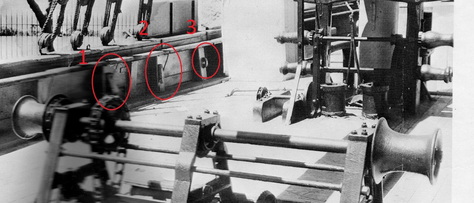
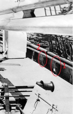
Hello all, I'm building a 19th century Norwegian yacht, Amundsen's Gjøa. I'm trying to identify some 3 things on the bulwark stanchions, two of them repeated both on port and starboard. The number '3' and maybe '2' I guess are some holders for the pump handle (can't see where else they could have put it, except below deck). Number 1 I can't begin to guess. It's no big deal if I never find out, as they are so small modelling them as they appear on the pics would be no problem, but I'm curious to know what they were used for.

-
Monthly update - despite horrible weather encouraging indoor activities I didn't do a lot. Painted the upper part of the hull and started with the backside decorations. I'm thinking to put some gloss lacquer on the wooden parts as the wood looks quite shiny on the vessels still floating. Followed by matt varnish everywhere. Not sure if that will take out the shine too much but we'll see. This kind of shine, as on her "near-sister" which I had the luck to see during this summer: Current state of paint. Looking at this image now I think the added planks are too thick... but it'll have to do. I also made a boo-boo by cutting the stem too short - you can see the extra piece I added on top to compensate. I will have to try to hide it better (there are many good reasons to paint ). And one with the stern decorations drying. Made them in several laterally bent 2 mm strip pieces. While waiting for the paint, I started on the deck furniture. I'm trying to built after the pictures and drawings of the original. There are plenty of detailed pictures of her in her current state, but lots have obviously been rebuilt/repaired and not with 100% faithfulness to the state in 1905. I'm trying to follow the few old original photographs and fill in what's missing from the new. I have more-or-less completed the deck house, the two WCs, the forward companionway, the hatch and started on the large skylight (test of concept picture below). Trying to figure out how to make the skylight. Testing to carve out recess and using that rock-hard packaging plastic for windows and cut brass tube for the holding ring. In the third post there is a picture from Norwegian maritime modellers' club (http://www.pbase.com/maritimmodellklubb/fartoyer) on Gjøa today showing how it approximately should look except that the windows have been removed now. Left to do is heavily laden with metalwork: winches, windlass, motorized pump (driven by messenger chains) and the small skylights.Not sure how to proceed, as I'm lacking tools to do especially the round parts and gears.


- 21 replies
-
- 6
-
-
- gjoa
- constructo
- (and 1 more)
-
Bolding mine: I'd be more than happy to be able to pack in these kind of details on twice the size... Stunning to say the least! I found your log searching for tips on metal working, and now I'm giving up on my hand tools and thinking which machines to buy (and where to buy the skills needed to use them ). The home-made photo-etch has fantastically well-defined edges, any change of sharing your procedure or a link to similar resources? Especially curious how you managed the profiles/variable depth (rivets, ridges).
-
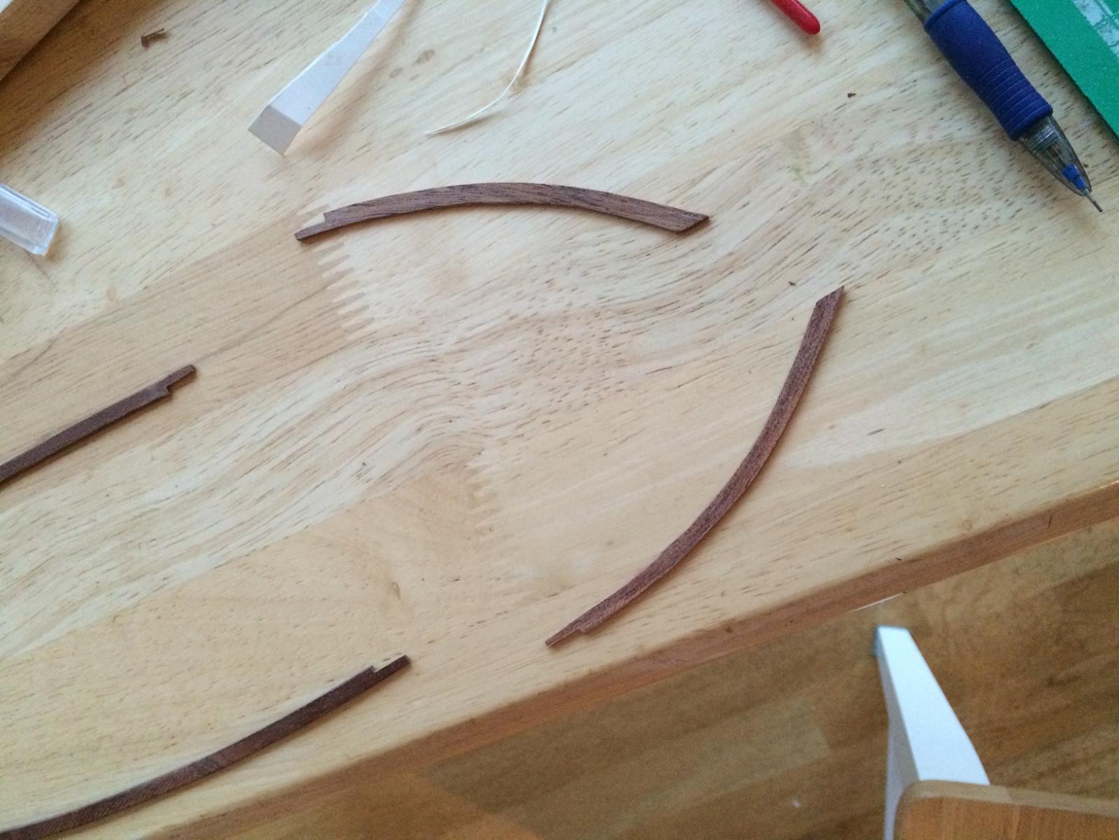
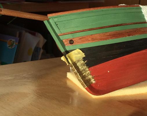
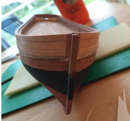
Progress at a snail's pace... the original was built faster Since the stem and stern are added outside the planking the construction does not feel robust - I drilled four holes front and back nailing them to the hull. I countersunk the holes and filled with a 'plug' of wood filler. The original seems to have the same reinforcements, so I will try to leave some contrast and let it be possible to see them. I'm building my way up the bulwarks, trying to copy the original as she appears now. Due to the paint scheme I'm following a strange procedure, only attaching the uppermost planks down to the in my case false extruding margin plank. The margin plank will be left natural or painted white (can't decide) and two more strakes will be natural, the rest green. The two green lines below the deck I am trying to shape without glueing, so that they can be painted separately and then mounted without the need of extra heat/soaking. Masking would be too complicated. What I'm aiming for: A view of the stern with the first piece of cladding with colour test. I'm redoing the opening for the tiller, not liking the fuzzy oval opening of the kit-supplied bulwark. The cap rail is also shaped to fit without attaching. I will paint it before attaching since I don't think I will be able to mask the millimeter-high part of the rail on the inside that should be natural. I expect that the top side will have to be sanded and repainted after gluing but that should be ok to do. The almost-straight pieces were made by left-overs from the hull planking, but I couldn't bend it to fit the bow profile. I instead lamintated three 1.5x2 mm strips of the same wood as the hull strips, bending them while gluing. The lines are barely seen unpainted so it should be good afterwards. Cap rail pieces and a front shot showing the cladding on the bulwarks:

- 21 replies
-
- 3
-
-
- gjoa
- constructo
- (and 1 more)
-
A couple of years ago the water level in Stockholm harbour was unusually low. On the beach of Kastellholmen island surfaced an unknown wreck suspected to be a 17th century Danish prize that later was deliberately sunk at the spot to act as pier. Only small parts remain, but interesting nonetheless. Pictures here, including a detail on what appears to show how a deck clamp was bolted to the frames: http://sv.wikipedia.org/wiki/Örlogsfartyget_vid_Kastellholmen
-
Here's the only picture I have found from before Amundsen bought her. It was taken during the expedition of the geologist Axel Hamberg who intended to study the icesheets/glaciers of the Arctic sea and Svalbard. That expedition was quite of a failure however as the skipper had no intention of keeping his deal with Hamberg, refusing even to close on the ice (Hamberg's money he kept though I suppose). Anyhow, some differences, except the propeller: five boats rather than three and different bobstay arrangement: More pictures from that journey: http://www.axelhamberg.se/Default.aspx?pageid=212
- 18 replies
-
- 2
-
-
- gjoa
- constructo
- (and 1 more)
-
Hello, I'm building the very same kit. Note that what you see there is the result of a century of weather and wind (if it even is the original deck), not only three years in the passage. The deck was pine I believe, so it would have been quite light in its youth.
-
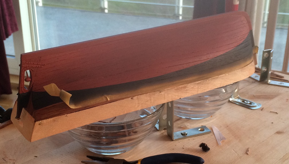
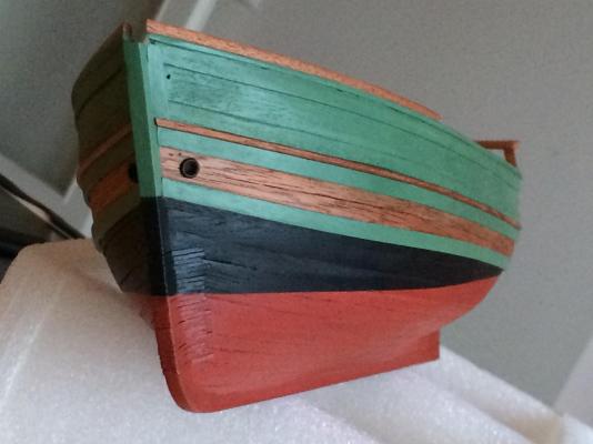
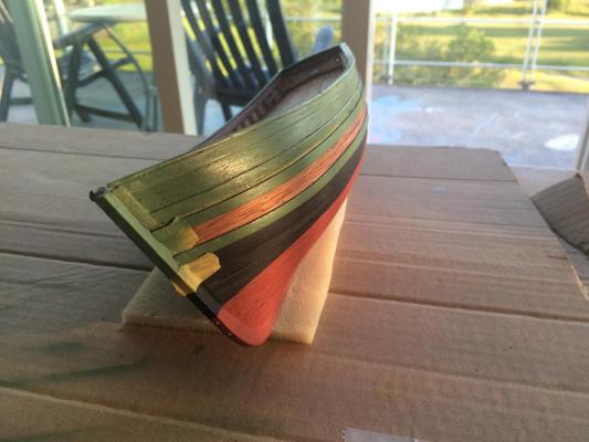
I decided to paint her as she appears now with red below the waterline, black up to the third strake below the deck, two natural strakes and green upperworks and wale. Looking at old pictures I suspect the natural wood strakes were painted white, but I like having some wood shine through and as long as I'm not sure I can convince myself that I can always paint it white later - but hardly the other way around. I also wanted to keep the rather 'used' look, and to accomplish this I will airbrush using much thinner and not using any primer. So far I've painted the red and the black and like the results to far: Last picture shows how long my home-made propeller made it... Not sure how to solve that. The bulwarks have been built up and is only missing the outer planking and caprails. The latter will be green so I plan to dry-fit them, remove and paint off the model rather than mask. The belaying pin rail was reinforced with brass rods through the false frame extensions. The picture below shows the construction after filling and sanding the outside and ready for the planking.


- 21 replies
-
- 8
-
-
- gjoa
- constructo
- (and 1 more)
-
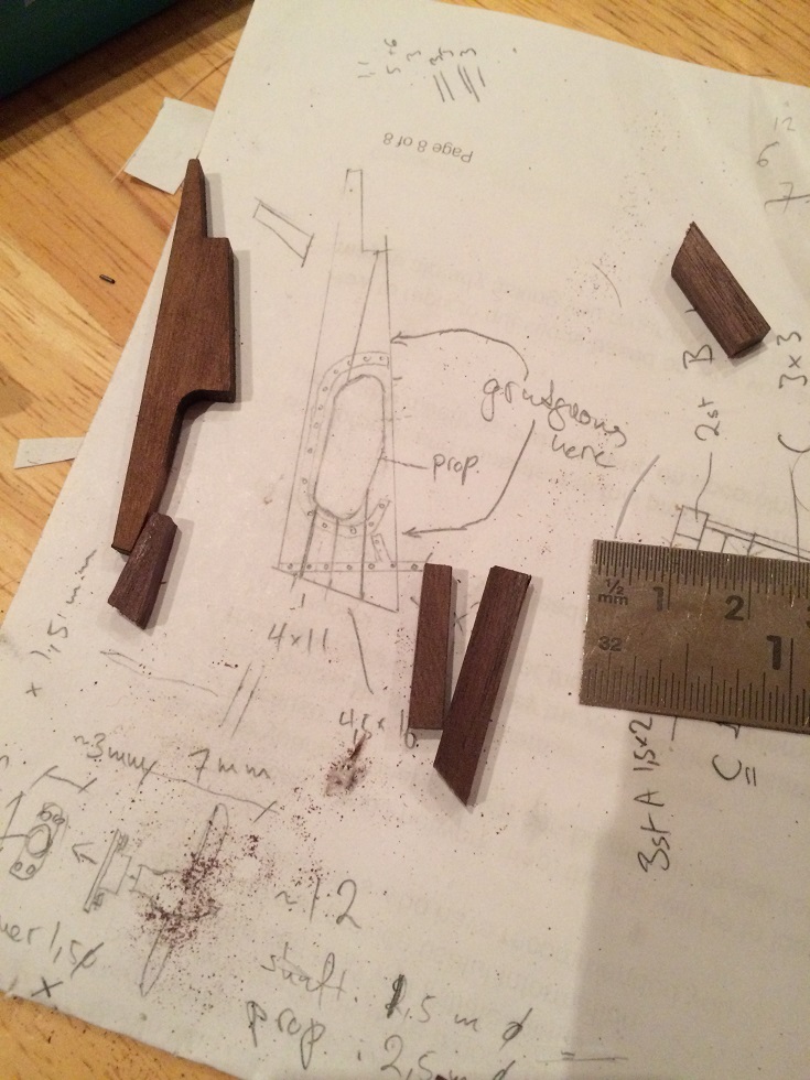
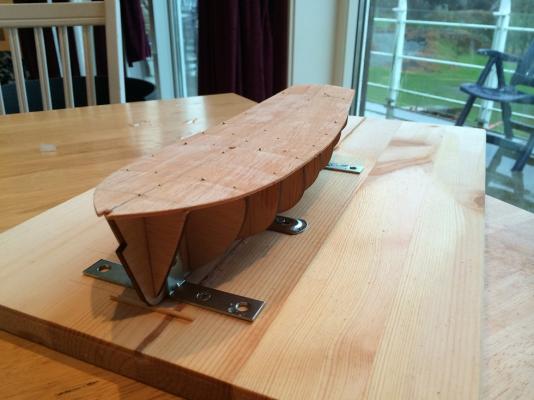
Recap continuation The keel and stem are added one top of the finished planking. This was a bit messy as I had to either cut into the planking or sand it down to a form flat even surface to attach the keel on. In the future I'll try to do the "traditional" way - this is also the point where I stopped reading the instructions. No matter how nice the booklet looks, the actual building is not that accurate either and is representative rather than replicating. I'm following drawings and images found on the net. Some filler was needed to close a gap between the garboard and keel, but this is ok as I will paint it over. The stem was way off from the original, with the propeller sitting far too close to the keel - I ended up re-building the thing from a sketch I took off the real ship (note the freudian slip =). The kit-supplied propeller is a three-bladed affair, so I remade it by cutting off two blades, reshaping the remaining to a much narrower design and soldered a scratch-made blade onto it, wondering how long that'd hold. The iron reinforcements and rudder hinges were modelled from brass sheet and rivets from .4 mm rods. Below is the finished planking, keel and stem.
- 21 replies
-
- 5
-
-
- gjoa
- constructo
- (and 1 more)
-
About the white bulwarks: I'm going to paint the model as I like the paintjob of these craft, often combinations of green, black, red and natural wood. Here's a few examples: Mathilde, http://www.hardangerogvossmuseum.no/hardanger-fartoeyvernsenter/norsk/fartoey-og-baatar/sj-mathilde.aspx Svanhild, re-rigged as a galeas: And Gjøa herself: ---
- 21 replies
-
- 2
-
-
- gjoa
- constructo
- (and 1 more)
-
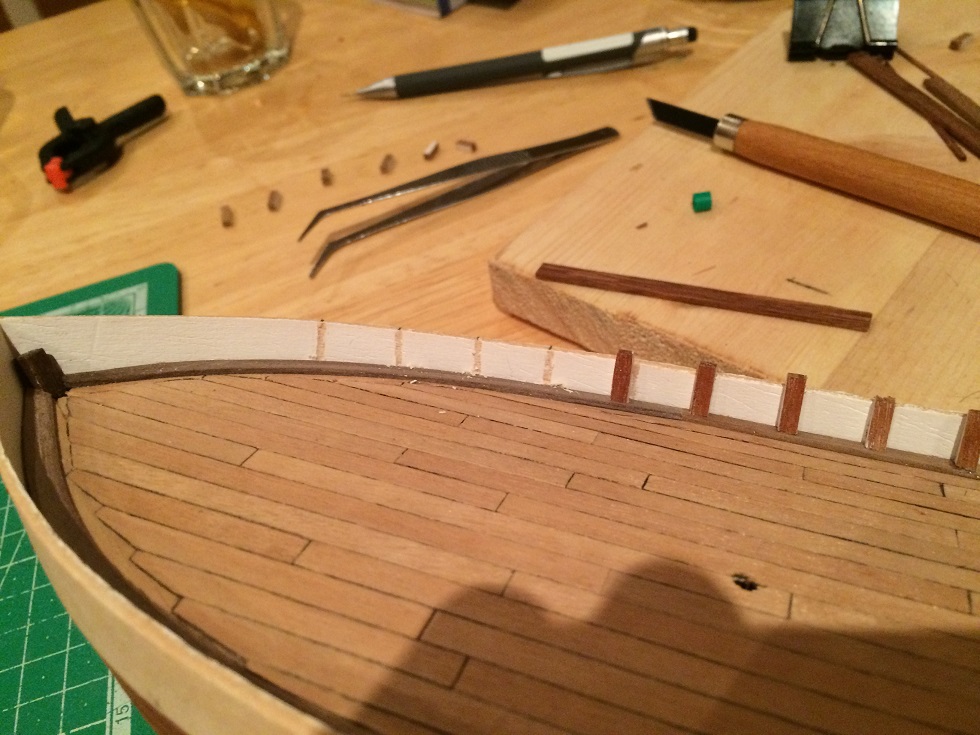
There are a lot of images of Gjøa in her current state here: http://www.pbase.com/maritimmodellklubb/gjoa_dekk&page=1 The deck was planked unevenly. I couldn't discern any apparent pattern from the pictures on the original, and went for a more or less random approach, but at trying to keep the butts where I thought it'd be deck beams. It's possible the deck's been repaired, but nevermind: The original deck was probably pine, so the light look of the kit-supplied wood should be ok. The bulwarks are built up with a laser-cut plywood sheet and planked on the outside. Kit supplied frame extensions to support them are 1x5 mm strips which I replaced with 3x3 mm tapered towards the top, as from the images, see image below. I'm not very happy how the joinery of the deck planks with the marginal turned out: the errors get really apparent on photo...

- 21 replies
-
- 5
-
-
- gjoa
- constructo
- (and 1 more)
-
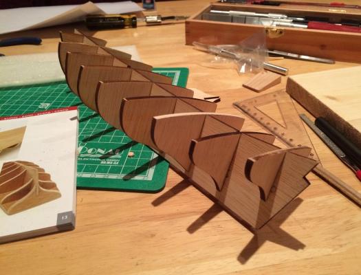
The kit comes with quite detailed constructions with plenty of pictures accompanied with short notes on what do in half the languages of the continent. Woods of three very different colours are supplied - I can never remember the exotic names. One is light like pine, another dark like walnut and one red-brownish colour which I've taken a liking too. By googling I had read rumours about Constructo's flimsy plywood, especially on this model, and wanted to proceed quickly after cutting out the keel and bulkheads. There was a small warp on the false keel already after cutting it free. I tried the method of wetting the concave side with hot water and put it into a jig. Most of the warp was gone the next day, but there was a small twist still on the aft section. This was removed by chopping away wood from only one side when removing wood to allow for the planking: the false keel will only have ½-1 mm of wood left to allow for the 1.5 mm planking on each side. The bulkheads fitted neatly - only one needed some serious sanding Here's a hint for future builders of this kit: if you use the kit-supplied bulkheads the lines will not be accurate for the last (or last two) bulkheads! I noticed this much much later, but I wish I'd known it here. The stern bulkhead sits too high/starts curving inwards too close to the deck, to that already the first strakes below the deck start twisting whereas on the original they don't. I'll put some pics on this later to show what I mean, I believe I don't explain it well. The false deck is a piece of thinner ply, which is to be bent to shape and fastened. This was not problem, it was just the right thickness to bend easily but not be too flimsy: The instructions had the deck planking as the next point, but I started planking the hull instead. Partly to make the structure more rigid, partly because I figured I would be rough with the deck while planking the hull. This is made with 1.5x5 mm strips from a the red-brown wood. The planking was a big pain somewhere below, with much forcing and twisting and bending the 1.5 thick planks in various unnatural directions they didn't want to bend. The instructions suggested using nails on every bulkhead to keep the planks in place, but I abandoned this after realizing that the thick nails would make the hull look like an inverted porcupine. CA was used at strategic locations to keep the wood in place until the casco-glue set. Here's pic of the first strake:
- 21 replies
-
- 5
-
-
- gjoa
- constructo
- (and 1 more)
-
Hello, This is a log over my first build, the yacht 'Gjøa'. I didn't plan to make a log - having very little spare time I thought I'd spend it building rather than writing, but a few days ago I found myself banging my head with the question 'what was that stain I used on half a year ago?!' Then I realized the value of a log.. especially when the progress is slooow. I've always been fascinated with polar exploration, not only is it the last frontier (or at least latest, since new frontiers tend to be opened up) but I also admire the lunacy required to venture into these areas. Gjøa was the first vessel to pass the North-West passage, captained by the greatest polar explorer of them all, Roald Amundsen. Being a small one-masted vessel it's also appeared to be a good starter model. And I really like the look of the rig. Gjøa is a hardangerjakt, which I believe would translate as Hardanger yacht, a vessel typical for the Hardanger fjord area in the 19th century. They were used for fishing and trading and several originals are kept in sailing conditions. Here's a whole bunch of them: Gjøa was built in 1872 and when Amundsen bought her in 1901 she had already spent many years sailing in Arctic waters between Greenland, Svalbard and Norway. She was rebuilt with a 13 hp engine and iron reinforcements against ice pressure. Much readings about the expedition through the North-West passage can be found online; I'll just mention that after the three-year long journey Gjøa was left in San Francisco where she stayed on display until 1972, when she was returned to Norway. Recently she was further renovated and now rests in a museum in Oslo together with Nansen's Fram. There's plenty of pictures of her online, which is extremely helpful. But also frustrating: they show plenty of errors and simplifications in the kit, but more on that later. I've been taking pictures of the built, so I will make a recap in the following posts.
- 21 replies
-
- 3
-
-
- gjoa
- constructo
- (and 1 more)
-
Fascinating subject! Building well-researched models could help sheddibg some light on the construction of these vessels (and a lot cheaper than building full scale replicas, goes without saying). Best of luck! Looks horribly unstable though, I have to admit. No wonder they didn't venture far or in bad weather.
-
Nice drawing The one thing that strikes me is that the heavy guns of a warship would be located a bit lower, and the channels should probably be above the ports. I think it helps to consider the internal deck placement when deciding the exact position of the guns. I agree that about 7 guns per side on the main battery deck seems reasonable for the size of Gripen.