Matle
-
Posts
123 -
Joined
-
Last visited
Content Type
Profiles
Forums
Gallery
Events
Everything posted by Matle
-
Unique 500 year old shipwreck in the Baltic sea
Matle replied to mic-art's topic in Nautical/Naval History
And another one found, this one from the end of the 16th century found on land in Stockholm. There’s plenty of buried old wrecks due to post-glacial land rise and hulks used as filler for man-made land reclaiming, but this wreck was relatively large and previously unknown. Built of pine from Hälsingland, which made identification easy: the only one fitting the records was the Samson, a Royal armed merchant built in the transitionary phase with mixed building styles. Sorry in Swedish, (and sorry it’s facebook), but there are some pics at least: https://m.facebook.com/story.php?story_fbid=2705387142816085&id=129042917117200 The wreck has been documented and then covered and protected for the future. -
Typos are as old as typography =)
-
Unique 500 year old shipwreck in the Baltic sea
Matle replied to mic-art's topic in Nautical/Naval History
Some boards of the aftercastle remains in place (seen in the video in the link), and it is clinkerbuilt just like on the later large warships of the first half of the 16th century. It also appears to have the rusty remains of two iron guns(one on each side), still sticking out through their ports. And there is at least one more gunport further forward and another further aft, though without guns. This makes me wonder if she is actually a small warship (or at least commisioned as such) as opposed to a merchantman as reported in Swedish papers, my guess is from the period 1500-1550, or even 1520-1570 (lots of naval activities in this area in this period, which should increase the probability of her having been parked down there). Six guns sounds too much for a merchantman of this size and age. I wonder what made them date her to the turn of the century (1500 that is), at least I can see nothing definite that would place her around either 1500 or 1550, for example. Anyway I bet they are wetting their pants in excitement over getting some wood up in order to date it, so we’ll know soon enough. And yes, that’s a pump alright, and the deck of some platform can be seen around the foremast, which well could be that of a forecastle (it is wider than the hull forwards). -
Unique 500 year old shipwreck in the Baltic sea
Matle replied to mic-art's topic in Nautical/Naval History
The recently found Mars (sunk mid 1500s), as well as Elefanten from the same time, also had round-tuck sterns and were carvel built. Gribshunden, which sank 1495, was built in the same way. Carvel became the dominant form of construction of larger ships in the Baltic during this time, but it is interesting to see a smaller ship built in the same style. —- Fabulous find- Even the boat is still there. I’ve been contemplating building a 16th century carvel ship, but with the rate they are currently uncovering new wrecks and how they were constructed my model would be built on obsolete information by the time I finished... -
Can i live without a BYRNES TABLE SAW
Matle replied to shihawk's topic in Modeling tools and Workshop Equipment
Oh, wish I’d seen that earlier - that is one opportunity not occuring often -
This was put on hold due to an upcoming move - I did not want to raise the mast before moving across countries. The move got postponed and postponed again. And now I am tired of its unfinished state. If the move does come and the model breaks, ah well, at least I tried and I’m truely sour how I bungled the deck planking anyway - I see the rest as practice. I added the mast and have begun with the shrouds. The upper dead eyes were connected to hearts (or whatever is the English term? - the white teardrop things) as was common in those days, and the shrouds looped around the hearts. How I made the hearts I do not remember, but the brackets are all brass. I have attached the first shroud on each side: now I’m trying to find out just how hard I should pull before permanently attaching the lanyards.
- 21 replies
-
- 7
-

-
- gjoa
- constructo
- (and 1 more)
-
To be honest I skipped every paragraph that started like that, as well as the simplistic «Viking» ship popular descriptions: I saw mostly the pictures, but they speak volumes :D
-
Wonderful Although interesting in itself, all those articles were more about 3D-scanning than the ship. It is maybe similar to the Galtabäck II wreck, which appears to be the same type of ship, from the same area and from within the same decade (or two). This period saw rapid changes in ship building though, and seems more intact than other wrecks, so this will generate interest for sure. And yes they did use iron nails at the time, alongside wooden, but they stay together anyway. At that time the boards were often fastened together with iron nails, while the frames, which were added later, were fastened with wooden ones. They say it is clinker built, but from the scan it looks like the uppermost boards could possibly have been built carvel style. That I have only seen on a single other wreck (also second half of 12th century), so that would be interesting to see more details about.
-
Beautiful Did I understand it right, that you print the wax, make a mould and then cast the final propeller, or am I missing something? What kind of material can you print the wax in?
-
I am as speechless as this is flawless. Thank you for sharing!
-
SS Mariefred by captainbob - 1:96
Matle replied to captainbob's topic in - Build logs for subjects built 1901 - Present Day
Indeed rigols - I've seen them made in a few logs on the forums on shipmodelinfo, where they make mostly modern boats, maybe you can find ideas there? Etching or casting would maybe work? Here is another view: Mariefred alongside quay in Mariefred I see darker pixels indicating carvings or reliefs inside them, but not more than that - how large would these things be on your model? Edit: I found a picture where you can see some detail, taken after the fire in 1980 before rebuild (you can search digitalmuseum.se for hundreds of old pics by the way): https://digitaltmuseum.se/011015402462/fo124957dia/media?i=291&aq=owner%3A"S-SMM"+text%3A"mariefred" -
SS Mariefred by captainbob - 1:96
Matle replied to captainbob's topic in - Build logs for subjects built 1901 - Present Day
I just strolled right in... might have changed since I moved but I got similar responces when I was living there. I think people just don't know about the place, it's a bit of an oasis, only minutes from the busiest areas of the city (this goes for Skeppsholmen too ). As a sidenote, this is where the Stockholm tar came from, the name of the place means "Tar isle". It does might be tricky to access the "parking lots" though, as they are usually fenced - but maybe one can get close enough for pics? -
SS Mariefred by captainbob - 1:96
Matle replied to captainbob's topic in - Build logs for subjects built 1901 - Present Day
She's parked on Beckholmen over the winter, if you are downtown someday (I used to stroll there, lots of old vessels to look on). Don't live in Stockholm anymore, so can't go and help out -
This has been said before but... can't believe it's "just" paper! For the record, the reason no one was on guard when the Anna Maria caught fire was quite specific: the drinks aboard were frozen solid so the last man left to join the others in the pub to warm himself with some of the still liquid variety. They were all awarded with a few days prison, after the shipowners asked the court to show leniency (makes me wonder if there were insurance frauds already then...).
-
For what it's worth, I remember an original drawing of an 18th century Swedish galley showing the same concave-convex arrangement on the joint of the two halves of each yard. So it seems like a persistent technology.
-
Grinnell & Minturn California line house flag + American clipper, I suppose it is Flying Cloud
-
Well, it's not cold all year round - that picture was taken in September, in Nome where, or so wiki tells me, the temperature ranges between 40 and 70 °F (5-20 Celsius) in September. Otherwise they were imitating local clothing, wearing furs: http://libweb5.princeton.edu/visual_materials/maps/websites/northwest-passage/amundsen3.jpg
- 15 replies
-
- 2
-
-
- gjoa
- polar exploration
- (and 1 more)
-
La Santisima Trinidad 1769 by Liberto - 1805
Matle replied to Liberto's topic in - Build logs for subjects built 1751 - 1800
Louie, maybe the carriages double as spacers for consistent positioning? -
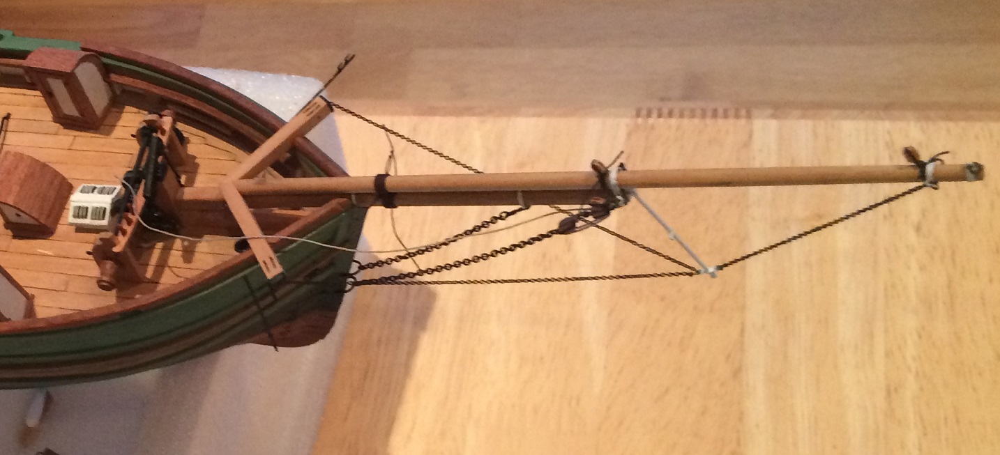
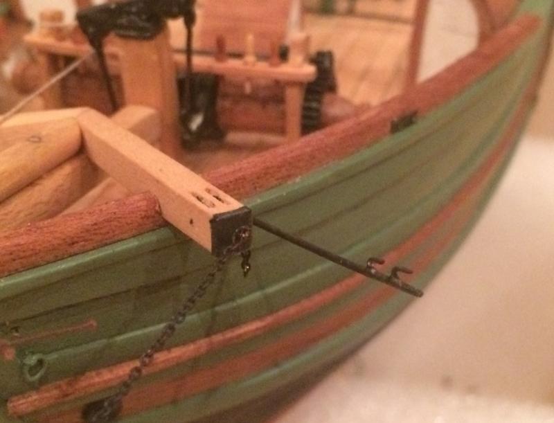
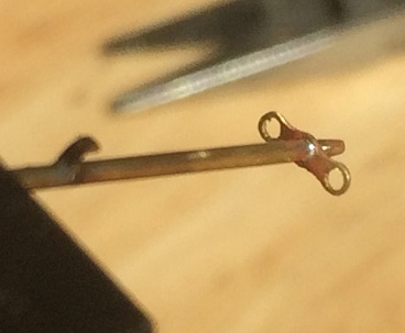
I base the rigging mainly on this image: http://digitaltmuseum.no/011014219978supplemented with numerous photographs of 4-5 still sailing vessels. There are some variations between the vessels in the details, but the overall rigging is quite similar. In addition Gjøa has recently been moved into a permanent indoor museum along with a partial restoration - the new fore rig seems identical to the linked contemporary picture. There are two chain bobstays. The lower terminates in a tackle with double blocks, and can be re-tensioned with a lanyard, which I belayed on the rail on the windlass. The dolphin striker was fabricated from a 1 mm brass rod tapered in each end, with a fastening bracket, fairlead and eyes cut and filed from brass sheet and soldered. The ball on the tip is a blob of solder, formed on the iron and carefully slipped onto the rod, careful not to heat too much to make it flow. The whole thing was painted white, as will be most of the iron work on the bowsprit and mast (for ref. caldercraft matt white). Chain martingales were "shackled" (read twisted copper wire with a little solder) to the aft eye and attached through a hole in the cat timbers in the other end. I used epoxy there. The front chain was attached to an eye in a band around the tip of the jib boom. Whisker booms were made from 0.7 mm brass. The two hooks were made from a single piece .4 mm brass bent to shape and soldered to the boom. Where the two pieces attacked, I file the pieces flat (removed 1/3 of the material) for a good surface to solder and keep the diameter down. They were not attached to the cat timbers, as seen on some recent images, but through the rail a bit behind them. This appears to have been corrected on the real thing in the latest restoration as well. I haven't added any shrouds yet as I will wait until after the stays and anchors. Below an image showing the current state. I have also attached gammoning and blocks for the jibs and square yard fore braces (the latter are the blocks on the sides of the tip of the bowsprit). Still have some stray pieces of rope to cut, but I haven't got a good tool to do it with (my blunt scissors produced results for the bin), so it'll have to wait.

- 21 replies
-
- 4
-
-
- gjoa
- constructo
- (and 1 more)
-
Antiquing a wooden ship
Matle replied to Bill Hime's topic in Painting, finishing and weathering products and techniques
I understand the goal is to make the new model look like an old model, and not as a new model of an aged ship (aka weathering), which is something else. Since this is basicly the same as faking antique furniture, I suggest you google just that: not for ship models but for how to make fake antiques - bitumen is regularly used for that purpose so I guess that is where that particular idea came from. Probably you can find more ideas in that department, since modellers usually are better at "weathering" -
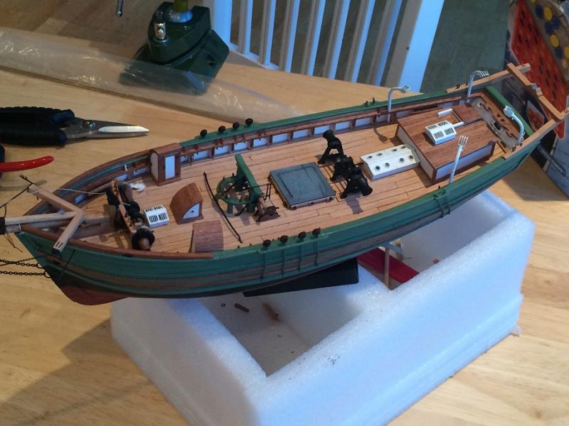
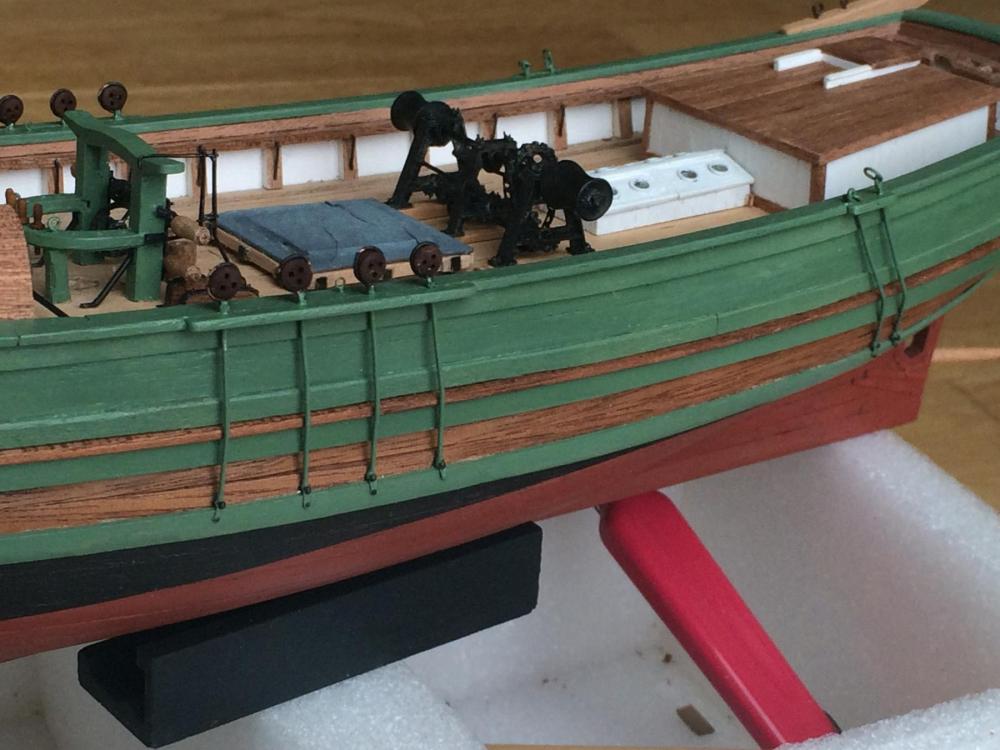
Major milestone reached: I have finally finished the deck fittings. The last item, the pump, has been prepared part-by-part but will be installed after raising the mast due to fragile parts. In the meantime I have drawn rigging plans (the kit plan is far from accurate) of all the rigging and added belaying pins for all the ropes. I will try to document the plan here so I have it saved. Here's an overview image of the rather crowded deck, the little vessel ready for rigging. I did start with the bowsprit rigging already while waiting for paint to finish on the last fittings, but I will document it in one post once finished - I still haven't installed the bowsprit shrouds.
- 21 replies
-
- 3
-
-
- gjoa
- constructo
- (and 1 more)
-
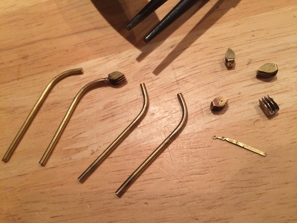
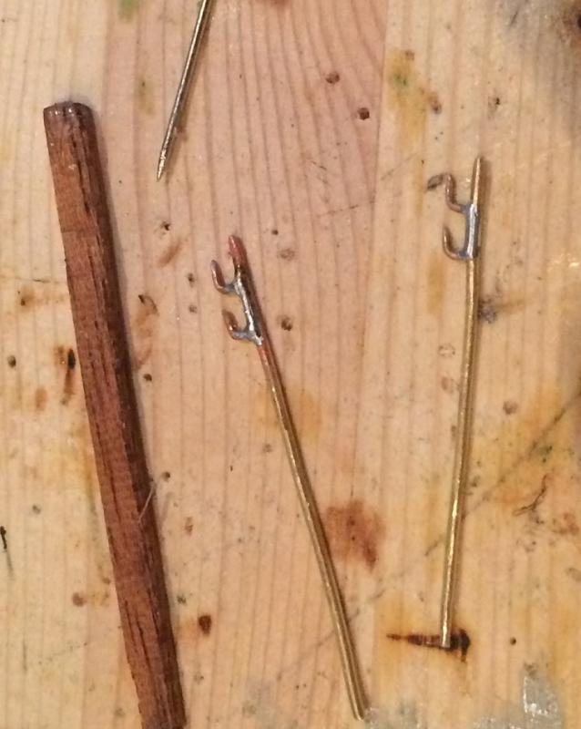
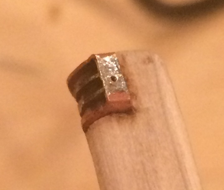
Gjøa carried three boats, one on the wooden stern davits and two on iron davits. I will probably make the boats last of all, but the davits better go on before raising the mast and its stays. Photo comparison shows the current davits are original. They have a three-sheaved pulley at the end, and simple cleats. See linked photos. http://m6.i.pbase.com/o2/55/752555/1/112920126.eNqlwtt8._M9J8794.jpg http://m6.i.pbase.com/o2/55/752555/1/112920136.Ll21Ge2V._M9J8804.jpg I made the davits from 2 mm brass, the eyelets or whatever they are called in English, were drilled and filed from brass sheet. The cleats were .4mm brass thread drilled and soldered into the davits. The pulleys were made from three pieces: one making up to two outer sides and the back which sits against the davit. The two inner 'wings' were soldered using positioning jig seen below. Holes for the sheave rod were drilled afterwards. A small positioning rod was drilled and soldered into the end of the davit, a corresponding hole drilled in the pulley which was initially glued to the davit to keep it in place during soldering. Holes were drilled in the pin rail and the davits test fitted. They still need sanding and several more paint layers, but since the paint tended to be sheared off when inserting into the holes, I first wanted to ensure I had big enough holes in the pin rail to avoid ruining the finished things. Please forgive me for the coin trick, wanted to try it at least once. I think I should have used 1.5 mm brass rod instead, they look slightly too stubby.


- 21 replies
-
- 4
-
-
- gjoa
- constructo
- (and 1 more)
-
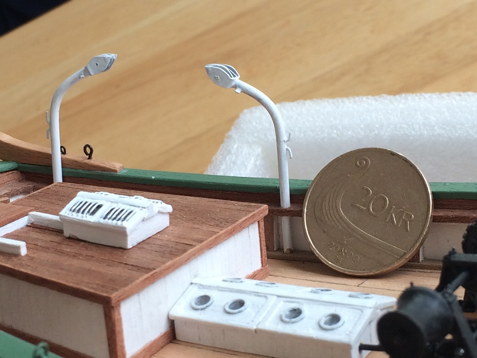
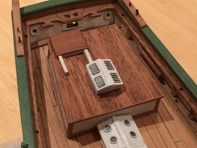
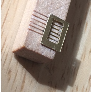
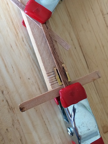
Thanks! Summer's over, at least here, and I've done some of the last work on the fittings. First, the skylights. There's two of them, one just aft of the windlass and one on top of the deck house. The image below shows the design. Both are similar but the deckhouse light appears slightly larger. I believe they are original. http://m1.i.pbase.com/o2/55/752555/1/112920141.taQyT3PK._M9J8809.jpg I've put this off since it caused me trouble: the protective bars are raised and I struggled to get these thin enough, strong enough and straight enough: the scale diameter is about 0.3 mm and on each lid there's 10 of them in the same amount of millimeters. After three failed attempts I found a method that I was satisfied with, I'll write in detail to remember till next time. The lid frames were made of brass with the openings for the windows drilled and filed. The bars were made from what the hobby shop marketed as 0.3 mm brass thread*, placed in a jig and bent together, the ends flattened with pliers for attachment to the frame - and greased with solder paste . A jig was made with grooves spaced 0.7 mm apart for the bars and the frame placed on top (upside down, photo below) with the flat areas pre-tinned with solder. Soldering was then made by simply heating the frames from the under side with the frame clamped solidly against the bars. Solder flows nicely to the soldering grease on the bars. Photos below show the frame on the jig and strapped ready for soldering. All except one of the 40 bars resisted my stress test, the last being superglued back. I then made wooden frames with windows inlaid, made from hard transparent plastic, and the metal frames (first painted white) epoxied on top. The lids were then glued on solid blocks and some detail added and then painted white. Finished result below. *) the fact that the bars stuck magnetically to my pliers and the golden colour got scraped off makes me suspect I've been duped. It did solder well enough though.
- 21 replies
-
- 4
-
-
- gjoa
- constructo
- (and 1 more)
-
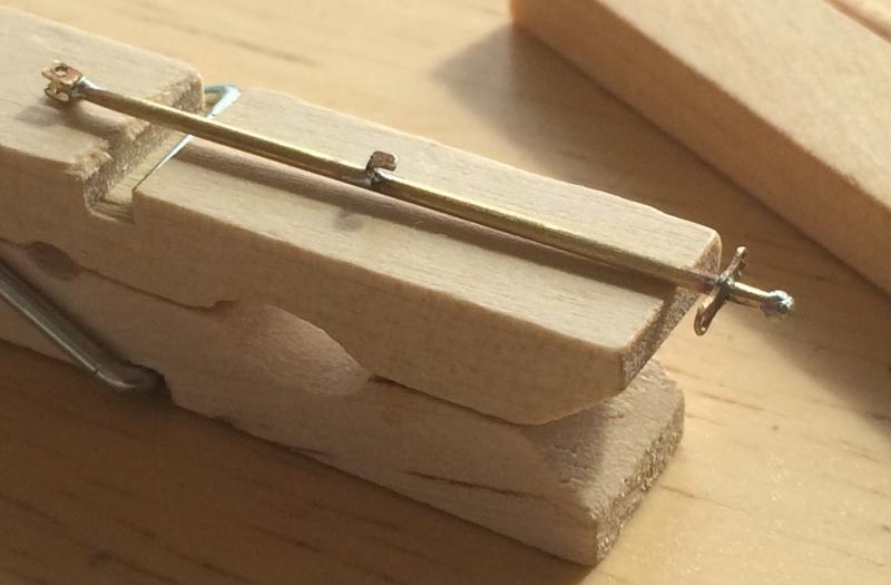
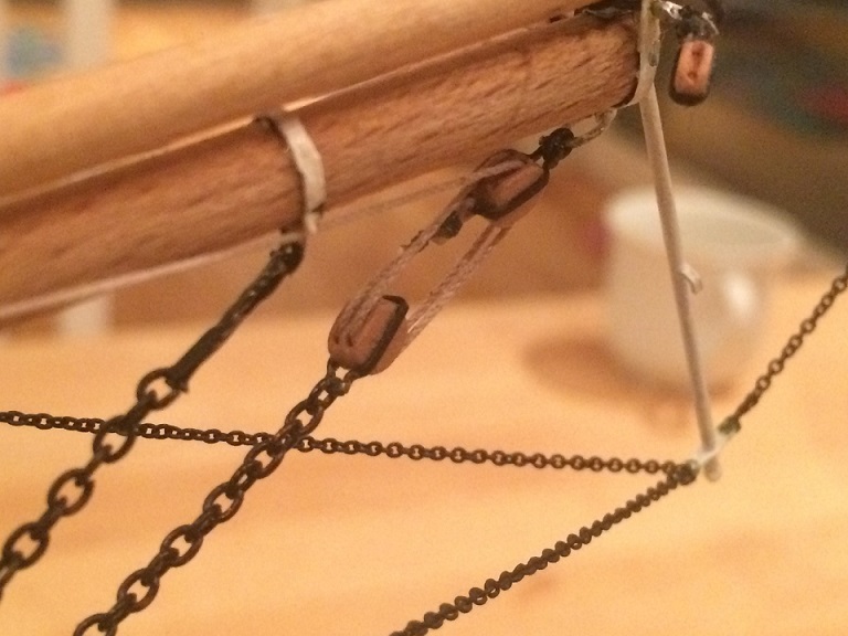
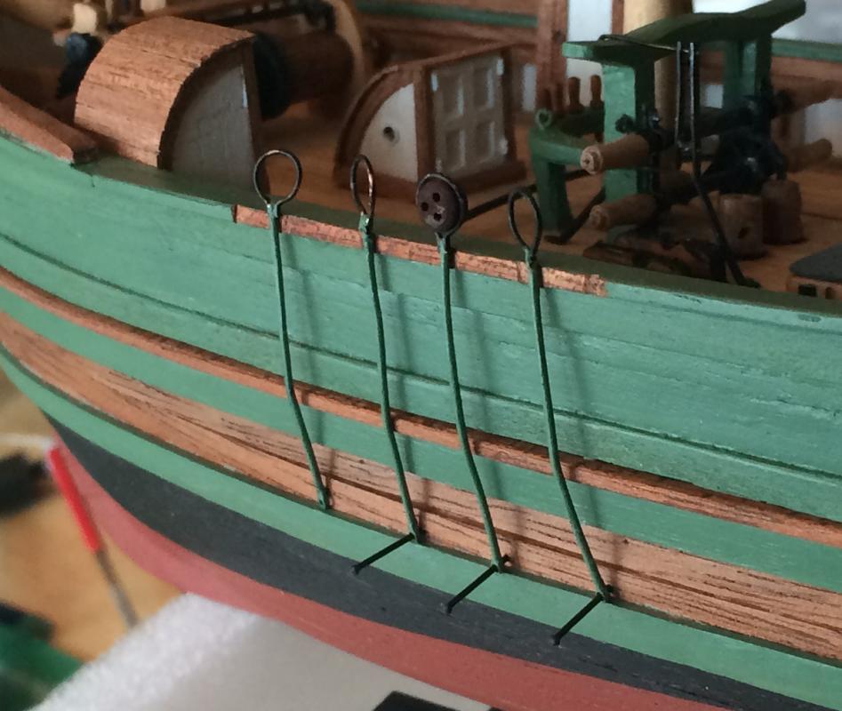
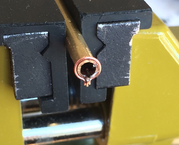
Thank you for that, it is encouraging. I'm a bit behind in writing, so I will try to catch up: Next on the list was the chainplates, which in this case are more like rods. Looking at this old image (http://dms10.dimu.org/image/022sA3QniuFe - a source of much information), it appears the chainplates are fastened to the unpainted wooden strake and not to the wale as they are fastened on the museum ship today. I can't see any backing brackets but this picture ( ) of a still sailing hardanger yacht (re-rigged with an extra mast) shows small backing brackets that are fastened on the lower wale - this is consistent with the original image of the Gjoa and I went for this construction. Chainplates are circular in cross section and made from .7mm brass rod. I soldered pieces ot brass tubing to make a hole for the bolt. Bolts were made by filing down the heads on brass pins. Backing links were made from brass sheet, cut, drilled and filed to shape. They became fairly similar, but if I have to do this again, I'd want to try to etch because it's quite a boring job. A little jig was made with a brass tube of suitable diameter to make consistent strops - image below. The strops were made from copper thread, flattened in the ends against the plate in the jig. They were soldered directly to the chain plates, in which small recesses were filed to take the strops. I managed to make four chainplates before realizing the strops were too small to pop the deadeyes in - note to future self, please take better measurements! Placing chainplates and drilling holes for the nails were made with the traditional dummy-shroud method. Deadeyes were from the kit, seemingly of correct size and shape. I just polished and stained them with walnut. The chain plates for the backstays were made in a similar fashion. Instead of deadeyes they are fitted with rings for the says. They can be seen in the image below, showing the finished result bar some touching up. I'm a bit unhappy with the joints between rail and channels, I'll have to be more careful next time. I also added a bunch of eyebolts and a rail for the staysail sheet.
- 21 replies
-
- 5
-
-
- gjoa
- constructo
- (and 1 more)
-
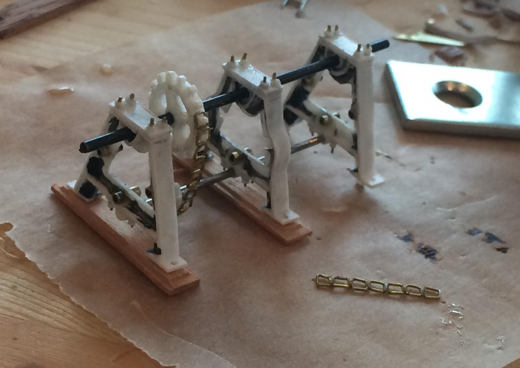
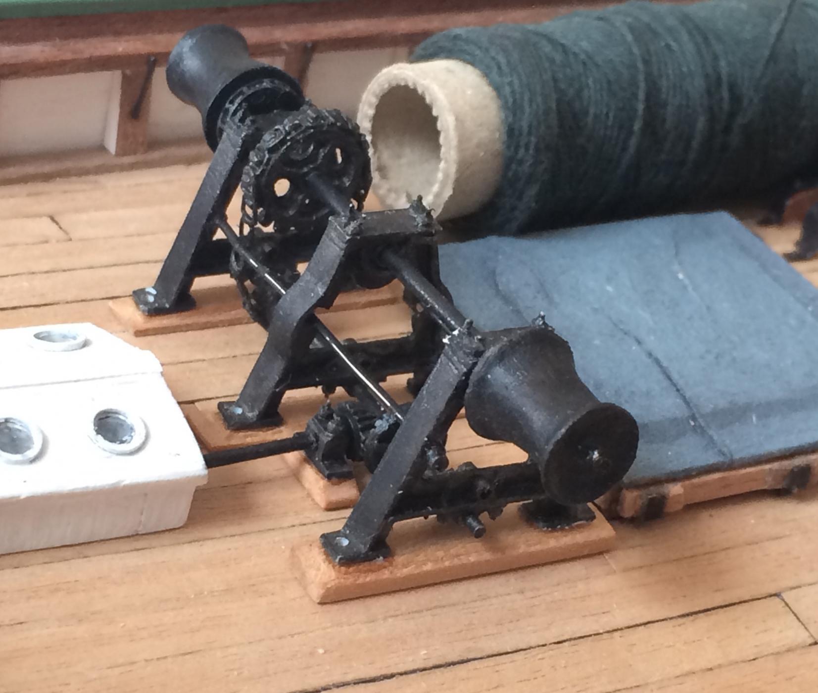
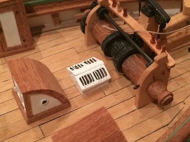
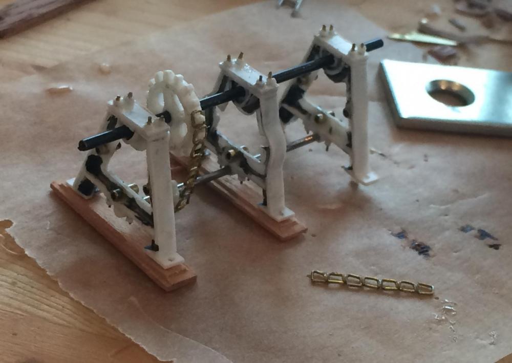
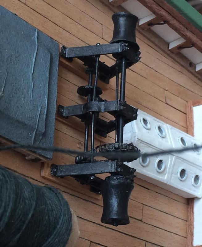
Gjoa. There. The search-function doesn't work with 'Gjøa' (can't find anything with ø), so I'm just adding the word spelled with o to be able to search for it. Before setting out on the trip through the North-West passage, the vessel was equipped with a small engine. Besides the propeller, it could power the pump or the windlass via a messenger chain. A shaft from the engine compartment came out on deck to a piece of equipment designed to change the gear and direction of speed, thereby rotating the messenger chain. Images of it can be seen here as it appears today: http://www.pbase.com/maritimmodellklubb/gjoa_dekk&page=3 Much of the stuff onboard today are replacements or restorations, but I believe this to be genuine. Seeing no possibility on how to make this is in metal to a level of detail I'd be happy with, I resorted to plastics. Styrene sheets were used to make the frames and the wheels. The two axles were made from brass tube respectively piano wire, since I wanted them to be absolutely straight. The two cylindrical supporting pieces were made from . 7 mm brass - they should look a bit dented in any case. The turnwheels were carved out of wood, but the chain connecting the upper and lower axles were made from 0.3 mm brass wire. I made a jig to create similar links and soldered or glued them together. Some images below, first from the attaching of the chain, the two latter from finished state (with exception of the bolts nailing them to the deck) - I was fearing this part at the onset and has delayed as long as possible, but I'm pleased with the result. It survived a couple of drops to the floor as well... Placed on the deck: Painting was made with airbrush and regular brush, Admiratly colours metal black mixed with Vallejo gunmetal . Writing this in case I need to repaint later.

- 21 replies
-
- 3
-
-
- gjoa
- constructo
- (and 1 more)