-
Posts
121 -
Joined
-
Last visited
About archnav

- Birthday 06/25/1966
Profile Information
-
Gender
Male
-
Location
Bavaria - Germany
-
Interests
Naval Architecture 17th and 18th Century, Ship modeling POF, original ropemaking, model ropery
-
 dunnock reacted to a post in a topic:
Rigging colors
-
 Archi reacted to a post in a topic:
Rigging colors
-
 Archi reacted to a post in a topic:
Rigging colors
-
 Keith Black reacted to a post in a topic:
Rigging colors
-
Marco Mercuri started following archnav
-
 ibozev reacted to a post in a topic:
Rigging colors
-
 ibozev reacted to a post in a topic:
Rigging colors
-
 ibozev reacted to a post in a topic:
Rigging colors
-
 archnav reacted to a post in a topic:
Interesting article on wreck of "Gribshunden"
-
 archnav reacted to a post in a topic:
Position of Channels on ships Hull
-
 archnav reacted to a post in a topic:
Position of Channels on ships Hull
-
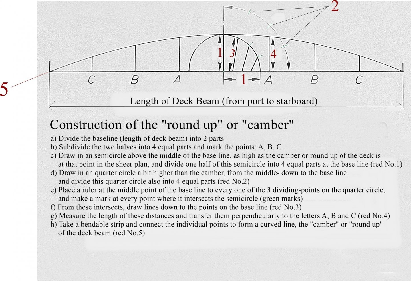
Hi Phil, unfortunately, there are very few explanations of this that can be used for the 17th, 18th and 19th centuries. David Steel 1805, Klawitter 1835 and other authors have given descriptions and drawings how to construct these deck cambers. Imagine, that the shipbuilders of that times had to "draw" this camber on every single deck beam. Only in midships where the length of the beams were nearly the same they could use the same pattern for all the beams in that area. I have made a construction template of how these lines were taken out on the beams sides. It is shown by Steel and Klawitter. If you study the way of construction, there is no doubt that the arc of every beam that is longer or shorter than at midships (to the aft and bow section), will differ in shape ! 😉 Make a try of this way of construction on CAD and you will see that the curvature of the deck, looking from fore to aft, will differ slightly. You will get NO fair lines along the whole deck. Of course, these discrepancies were hardly noticeable, but they were noticeable if you looked closely. The line of the camber definitely showed more of an ellipse but in no case a linear curve. I think one cannot apply the old construction methods to the 20th century, that would be a mistake. I hope my post helps you all.
-
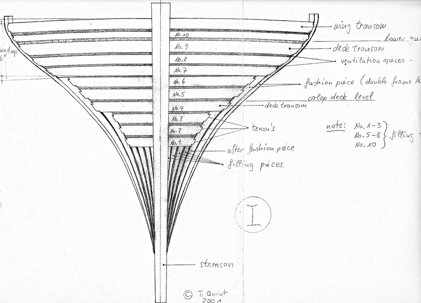
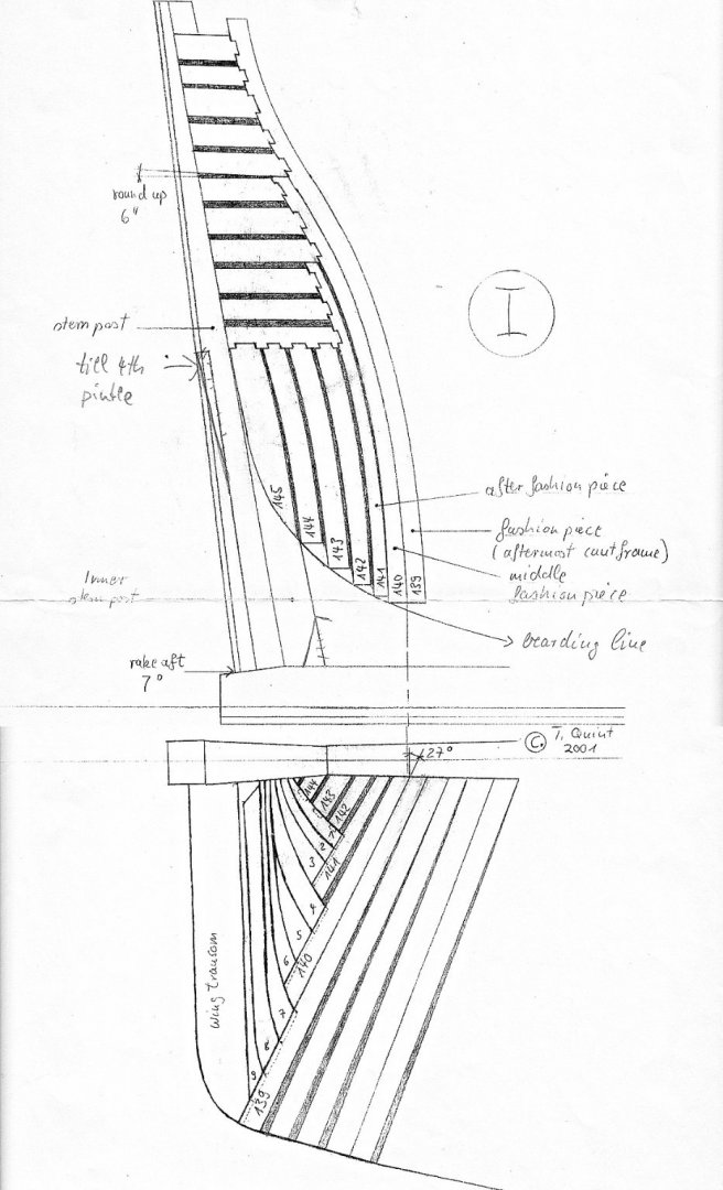
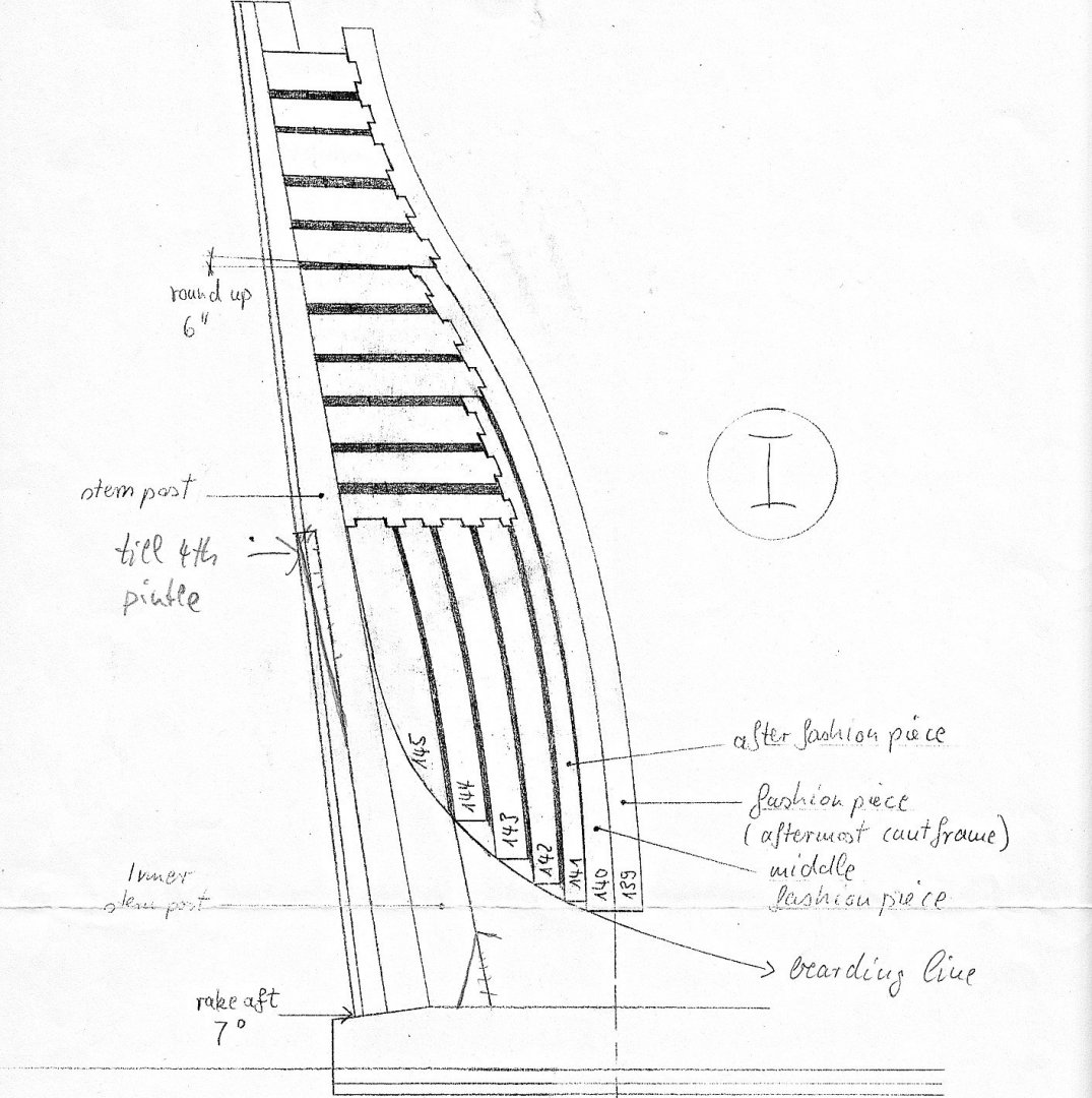
Hi Don 20 years ago I was deep in research work of HMS Victory. I visited the ship several times in the 1980`s and 1990`s. When studying the plans of Mr. John McKay / Canada, I was very disappointed. I started redrawing the framework, in particular the Stern timbers. The fallowing drawings are in made in 1:48 and I was told in 1985 from the carpenters on board that the original Stern Transoms had tenons for the connection into the fashion pieces. See my drawings. The work of David Steel can be used back until about the 1770`s - he adopted much of his work from earlier writers such as Stalkartt and "Shipbuilders Repository". I hope this is of help.
-
Hi Allan, sorry that my answer above was so detailed, but I thought it would be interesting to you. It`s sad to here that Chuck is no longer producing model rope, it was quite looking good. If you and others are interested: In the meantime I have built the fifth model-ropery and developed a professional machine that can twist at 4500 rpm. I have spent many years developing a professional machine, also the production of optimal cordage has cost me many thousands of attempts. Today, however, I am able to produce model ropes between 0.1 mm and 8 mm in diameter. Two-stranded, three-stranded, four-stranded with core, hawser layed or cable layed. I have experimented for a long time to be able to produce the perfect model rope and have orientated myself on the production techniques of the 17th and 18th centuries. I have studied all the books and documents from this period in detail and will also write a book about it one day........if I live that long. I have already thought about whether I should post a detailed report on the production of a professional model ropery, because that is a lot of work and at the moment, as you have noticed, I am still busy researching the ENDEAVOUR. I would also show the making of model rope step by step. Most model ropes are far too soft and loosely twisted and can be pulled apart like chewing gum with the slightest strain. This is a common problem with those who try. But that's only because they don't yet know exactly how to do it, that's all. The machine and the knowledge are elementary prerequisites for success. So if there is interest, I will make an effort to make an appropriate post. A longer introduction to the basics of rope making and a bit of historical knowledge, would then be the first areas. So if that is really wanted, then I will try to do my best.
-
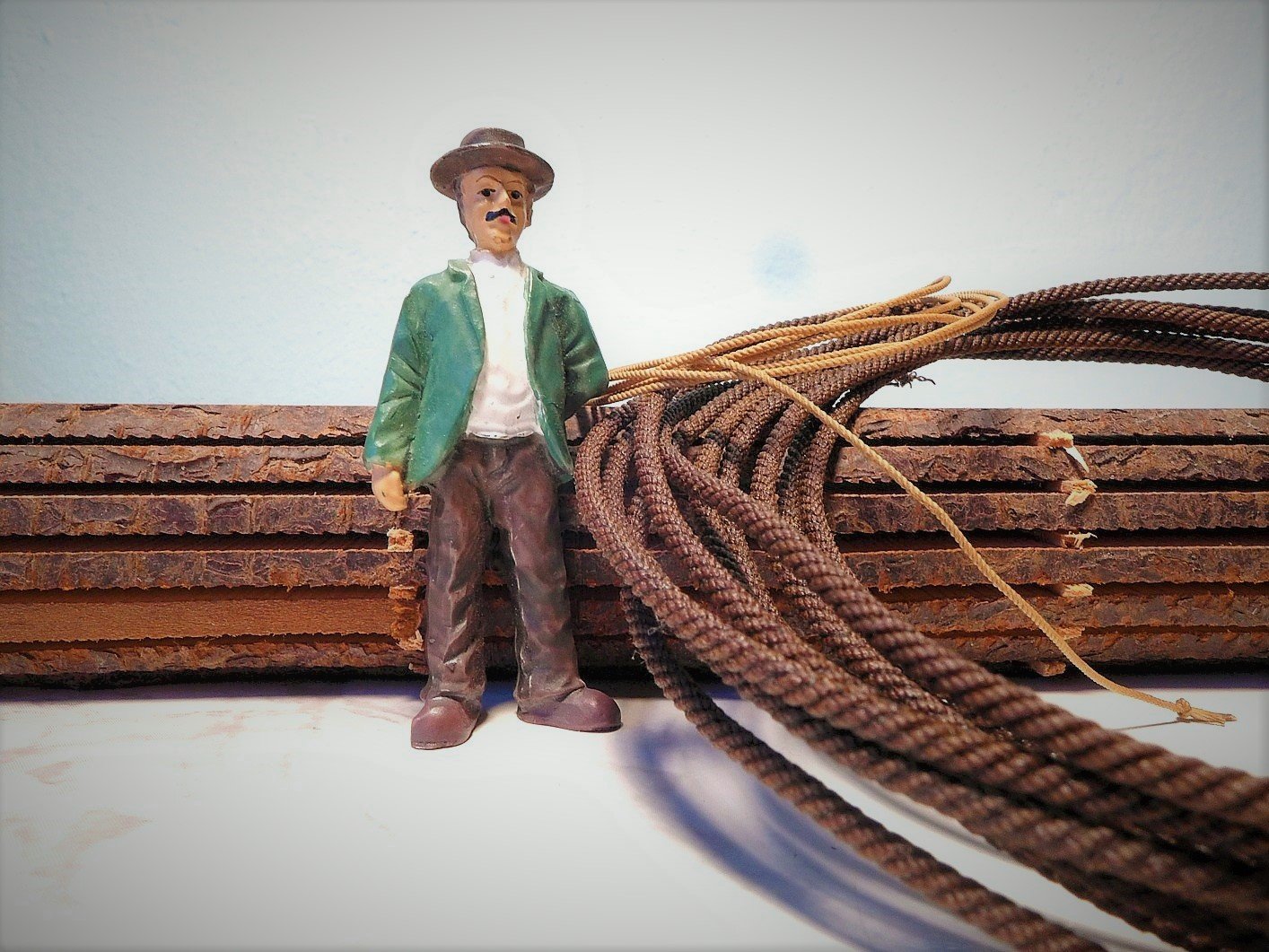
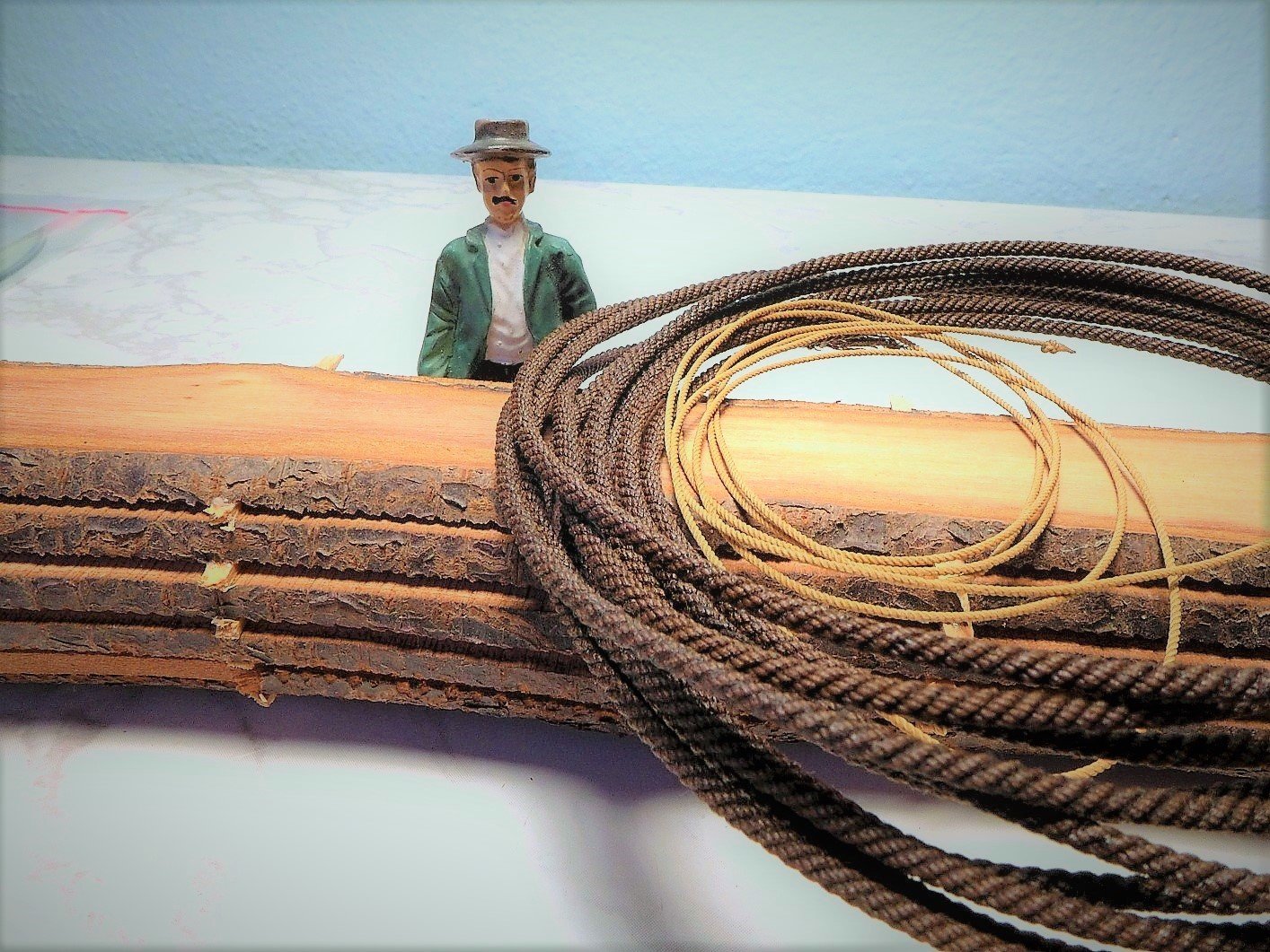
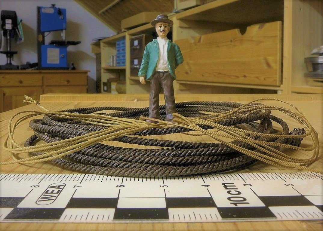
Hi Allan, in 2003 I was in Stockholm visiting the Vasa museum. I was in contact with Hans Soop, the author of several books on the sculptures and figure decoration of Vasa. He invited me and introduced me to the director of the museum, who gave me unrestricted access to the ship. I could move around the ship freely all day and that was an absolute privilege at the time. I had many interesting conversations with the people from the Vasa Museum and I also learned something about taring the rigging. I did a little round trip with a friend through the Nordic countries like Sweden and Denmark and we stopped in many coastal towns to see the maritime museums there and talked to the people. It was in a small fishing village in Sweden, I can't remember the name, that I noticed a boat builder who was still tarring his ropes as in old times. At that time, he told me the recipe with which the original "Stockholm Tar" was made and still is. He gave me an old tin of his mixture, about 250 ml, which I brought home with me. I also visited the original rope factory in Roskilde in Denmark, which made the cordage for the Viking ships. There, too, they showed me how the tar is made. When I started to work intensively with cordage and its production more than 10 years ago, I also made my first experiments with tar. I learned how to refine the recipe so that it could be used for model ropes to dye dark and light ropes. It took a few tries, but the result is so authentic that by now I only use original linen yarn and genuine Stockholm tar. Of course, the production of such cordage is complex costly and time-consuming. But the result is extraordinary. I made the rope in the photos more than seven years ago and it has not changed in colour. It is a real cable, four-stranded with a core, for a stay or a shroud. There is only one dealer in Europe who imports original charcoal tar "Stockholm Tar". But you can hardly work with tar alone. It has to be specially diluted and mixed with other substances so that it can be used. So it needs a special recipe. The rope must also be treated with it in various stages of production. Just dipping the finished rope into the tar does not bring success. The production of such ropes is really extremely complex and hardly anyone wants to do so. In any case, I think it is worth it, because the modellers of the time also worked with natural dyeing and preservation methods.
-
I would take a little more darker brown.....about the same as your mast wooldings are
-
I know it's a bit unusual, but I use real linen yarn and make my ropes on a specially designed machine. I dye my ropes exactly the way it was done back then, with real Stockholm tar. The following photos are just an example of how well this works and how real it looks.
-

Mast Lengths and their above deck heights for HMB Endeavour
archnav replied to dashi's topic in Masting, rigging and sails
David Steel: The Elements & Practice of Rigging and Seamanship 1794 1) HEIGHT OF MASTS IN THE ROYAL NAVY Mastmaking – Page 39: Rule: Length of Lower Deck + extreme breadth : 2 → Height of Main mast - Mast: For ENDEAVOUR - Main mast: 58ʹ 5" - Fore mast: 8/9 of Main mast 51ʹ 117/64" - Mizen mast: 6/7 of Main mast 50ʹ 055/64" - Main topmast: 3/5 of Main mast 35ʹ 019/32" - Fore topmast: 8/9 of Main topmast 31ʹ 155/64" - Mizen topmast: ¾ of Main topmast 26ʹ 37/16" - Topgallant mast: ½ of Topmast 13ʹ 123/32" - Bowsprits of 80 gun ships and upwards: 7/11 of Main mast --- - Bowsprits of 74 gun ships and under: ⅗ of their Main masts 35ʹ 019/32" 2) DIAMETERS IN PROPORTION TO THEIR LENGTH Main- and Fore mast: - of ships of 28 guns and under ⅞ of an inch to every yard in length Mizen masts: - of ships of 50 guns and under ⅔ of the diameter of the Main mast Main- and Fore Topmasts: One inch to every yard in the length of the Fore topmast Mizen topmast: 7/10 of the diameter of the Main topmast Topgallant masts: One inch to every yard in their lengths Bowsprits: - in 50 gun ships and under The same diameter as the Main mast 3) PROPORTIONAL LENGTH IN YARDS, IN THE ROYAL NAVY Main yard: 8/9 of the Main mast Fore yard: 7/8 of the Main yard Mizen yard: 6/7 of the Main yard Main-topsail yard: 5/7 of the Main yard Fore-topsail yard: 7/8 of the Main-topsail yard Mizen-topsail yard: 2/3 of the Main-topsail yard Topgallant yards: - Seventy-four gun ships and under 3/5 of their topsail yards Crossjack yard: The same as the Fore-topsail yard Spritsail yard: The same as the Fore-topsail yard Spritsail-topsail yard: The same as the Fore-topgallant yard Studdingsail yards: 4/7 of their booms Driver yard: The same as the Fore-topgallant yard 4) PROPORTIONAL DIAMETERS OF YARDS Main- and Fore yard, at the slings: 7/10 of an inch for every yard in length Mizzen yard: 2/3 of the diameter of the Main yard Topsail yard: 5/8 of an inch to every yard in length Topgallant yard: 6/10 of an inch to every yard in length Spritsail yard: The same diameter as the Fore-topsail yard Spritsail-topsail yard: The same diameter as the Fore-topgallant yard Studdingsail yards: One inch in diameter to every 5 feet in the length Crossjack yard: The same diameter sa the Fore-topsail yard Driver yard: The same diameter as the Fore-topgallant yard 5) PROPORTIONAL LENGTH OF BOOMS Lower Studdingsail booms: 5/9 of the Main yard Top Studdingsail booms: ½ the length of the yards they go on Flying Jib boom: 5/7 of the Bowsprit 6) PROPORTIONAL DIAMETER OF BOOMS Studdingsail booms: One inch to every 5 feet in the length Flying Jibb booms: 7/8 of an inch to every yard in the length 7) PROPORTIONAL LENGTH OF GAFFS Length of the gaffs: 5/8 of their respective booms Diameter of the gaffs: The same as their booms PROPORTIONAL LENGTH OF STAFFS Length of the Ensign staff: ⅓ of the Main mast, above the Taffarel Length of the Jack staff: ½ the length of the Ensign staff, above the Taffarel Diameter of the Ensign staff: Half an inch to every yard in the length Diameter of the Jack staff: ¾ on an inch to every yard in the length 9) Masts and Yards &c. for Boats Long boats, sloop fashion, but with Lug-sails Length Main mast: Twice and half the breadth of the boat Main yard: 5/8 of the Main mast Fore mast: 7/8 of the Main mast Fore yard: 5/8 of the Fore mast Bowsprit: ½ of the Main mast Diameters in frictional parts of an inch to every foot in length Main mast: ¼ Fore mast: ¼ Main yard: ¼ Fore yard: ¼ Bowsprit: 5/8 Pinnaces with Latteen-sails Lengths of the Masts: Twice the breadth of the boat and 8 inches added Length of the Topmasts: The length of the mast and 1/9 more Scarf of the Lower mast: ¼ its length Diameter of the masts: 5/16 of an inch to every foot in length Diameter of the Topmasts: 2/10 of an inch to every foot in length Pinnaces and yawls with Sprit-sails Lengths of the Main- and Fore masts: Twice and ¼ the breadth of the boat Length of the Sprits: ⅛ more than the mast Diameter of the masts: ¼ of an inch to every foot in length Diameter of the Sprits: ⅛ of an inch to every foot in length archnav - January 2021- 63 replies
-
- HMB Endeavour mast lengths
- above deck mast heights
- (and 3 more)
-
Hello Hans, you know I love your model and your ropework looks so beautiful ! Last stage and never forget the motivation before you retire. Just imagine all the time you'll have to finish your little French girl. I wish you a wonderful last working period and when the time comes, we will celebrate. ( Yo baby - Yo baby - Yo baby - Yo ! ) 🤪
-

Mast Lengths and their above deck heights for HMB Endeavour
archnav replied to dashi's topic in Masting, rigging and sails
Gentleman, after a long time with health problems, I am back and I´m deep into research again since a few month. I have started a new topic: Regarding to this topic here: There are new informations about the question, why the mizzen mast of the ship is given so short in the Gray-List. The answer I found is very simple. Apparently the mast and yards, after the voyage, were measured only by the parts, that were not rotten ! As Cook himself wrote in his Log when coming home, the mast and yards were in very bad condition.....rotten away, and also the rigging in very bad condition, main top-backstays broken etc. The rotten wood of the masts was no longer usable and was probably sold on cheaply. To do this, however, it had to be measured precisely and this was recorded in the Gray list. Apparently it was common knowledge that masts that were not built were more susceptible to dry rot than built masts. Cook also mentioned this once in relation to the small merchant ships in the coal trade. There is testimony from a researcher who has studied Cook and the Endeavour extensively that this was a common practice in the Royal Navy. It certainly seems logical. This would make all the speculation about why the mizzen mast of the ENDEAVOUR is so short superfluous. I am in the process of contacting this woman and getting one or more sources where this can be read. However, this statement must be true, as it has been published in scientific circles. I too have done all the possible variations for the calculation of the masts and yards and will publish the results in this topic here. I hope that I could again contribute something to answer the unanswered questions or come close to it.- 63 replies
-
- HMB Endeavour mast lengths
- above deck mast heights
- (and 3 more)
-
archnav changed their profile photo
-
Hi Siggi, what a beautiful work ! When using Balsa wood, it get`s "hard" when you coat the surface with diluted wood-glue, one or two times. The wood soakes the glue and the surface gets hard. A positive side-effect is, that planking is easier to do, because the surface is primed with glue yet Weiterhin viel Erfolg !
-
Hi guys, the fallowing links, showing these wooden timbers (bumpers) below the gunports. They`re only fixed on 19th century models of the NMM. So the question arises again, if it was possible, that these "carriage-stops" were fitted long before - see HMS Colossus. Unfortunately, no model before 1800 existing, nor any other evidence except the wreck of this seventy-four gin ship !? These models also show the mentioned half-ports, washboards and port-lids. http://collections.rmg.co.uk/collections/objects/68891.html http://collections.rmg.co.uk/collections/objects/68912.html http://collections.rmg.co.uk/collections/objects/68944.html http://collections.rmg.co.uk/collections/objects/66743.html http://collections.rmg.co.uk/collections/objects/68960.html Couldn`t find any more...maybe anyone has more information about these details ?
-
By the way... if these "half-ports" mentioned in Steel`s work, are the same type the french used at that time, it is clear why models do not show any of these ! The french version shows, that these very completely removable and only used in harbour. The so called "washboard" is also shown. It is very close to the finds in the gun port of HMS Colossus, remember the wooden "battens" for a thin washboard to slip down into it, with a semi-circular hole for the gun barrel to fit into. Maybe this was a standard fitting in preparing a ship for service. That`s why David Steel mentioned it. One can also speculate, that half-ports were in use already before 1800, because Steel took about 20 years to ask his sources and arrange all informations before he was able to write his work down. Examples for obsolete Informations existing in case of Masting and Rigging.
-
Today, I`ve taken a look in some of my books. Not very much is written on "half-ports". Though some have interesting sections also regarding "bumpers". I`ve made a little list here in the hope, that everyone of you do have these books in your library: 1) The NRG: Ship Modeller`s Shop Notes Vol.I - Pages 121 - 123 2) Milton Roth: Ship Modeling from Stem to Stern - Pages 204 - 208 3) Charles G. Davis: The Built-Up Ship Model - Pages 117 - 119 4) Jean Boudriot: The seventy-four gun ship Vol.II - Pages 164 - 167 and Plate XXXIX between Pages 172/173 Searching for more...
About us
Modelshipworld - Advancing Ship Modeling through Research
SSL Secured
Your security is important for us so this Website is SSL-Secured
NRG Mailing Address
Nautical Research Guild
237 South Lincoln Street
Westmont IL, 60559-1917
Model Ship World ® and the MSW logo are Registered Trademarks, and belong to the Nautical Research Guild (United States Patent and Trademark Office: No. 6,929,264 & No. 6,929,274, registered Dec. 20, 2022)
Helpful Links
About the NRG
If you enjoy building ship models that are historically accurate as well as beautiful, then The Nautical Research Guild (NRG) is just right for you.
The Guild is a non-profit educational organization whose mission is to “Advance Ship Modeling Through Research”. We provide support to our members in their efforts to raise the quality of their model ships.
The Nautical Research Guild has published our world-renowned quarterly magazine, The Nautical Research Journal, since 1955. The pages of the Journal are full of articles by accomplished ship modelers who show you how they create those exquisite details on their models, and by maritime historians who show you the correct details to build. The Journal is available in both print and digital editions. Go to the NRG web site (www.thenrg.org) to download a complimentary digital copy of the Journal. The NRG also publishes plan sets, books and compilations of back issues of the Journal and the former Ships in Scale and Model Ship Builder magazines.


