


Jaager
-
Posts
3,084 -
Joined
-
Last visited
6 Followers


About Jaager

- Birthday 09/11/1946
Recent Profile Visitors
6,983 profile views
.thumb.jpeg.ffac2f8a24d212961a83eab4efb06a6c.jpeg)


-
 phebe reacted to a post in a topic:
Philip Reed style Navy Board models: are there any on MSW?
phebe reacted to a post in a topic:
Philip Reed style Navy Board models: are there any on MSW?
-
Taygz reacted to a post in a topic:
Looking for the Correct Sequence and Terminology for Deck Plank Butt Shift
-
KeithAug reacted to a post in a topic:
Thurston saw blades
-
 Zocane reacted to a post in a topic:
Best paint for wooden ship models
Zocane reacted to a post in a topic:
Best paint for wooden ship models
-
miloman reacted to a post in a topic:
Wood Glues
-
miloman reacted to a post in a topic:
Wood Glues
-

bolting frames onto keel
Jaager replied to hamilton's topic in Building, Framing, Planking and plating a ships hull and deck
From the above, I would bolt the keelson to every timber. With a bolt already in every other timber a pattern that avoids having the keelson bolts and existing timber bolts on different tracks is needed. A "Z" with the hole 4" in from the edge of the keelson and since the floors are sided 11" ( 11/3= 3 2/3") about 3.5" in from the edge of the floor. The next timber would be a mirror. The floor bolts having the same pattern - staggered by one timber - but since it not visible, the floor to keel bolts can be skipped. -
bolting frames onto keel
Jaager replied to hamilton's topic in Building, Framing, Planking and plating a ships hull and deck
1. You do not make it easy when not identifying the class and year of Echo. 2. If you are at all serious about 18th C. RN vessels and aim at authenticity you should own a copy of Yedlinsky. 18 gun sloop of war: Floor timber : Every other floor timber to be bolted through the main keel - bolt dia. = 1" Keelson : To be square = 12" x 12" exclusive of what is let down between the floors which may be = 7/8" Scarphs in length = 4' 6" The keelson bolts should be driven through and carefully clenched on the underside of the main keel dia. = 1" Excepting where the rabbet for the plank is taken out in the middle. There, they come through and clench on the underside of the keel that is coaked to the main keel. -
Working from a fixed inventory, I am not surprised that Donna may have depleted Model Machines inventory. You may wish to try email and see what is left that you want by contacting Donna. Malco seems to offer single blade purchase on these pages: https://www.malcosaw.com/product-category/high-speed-steel-saws/jeweler-s-slotting-saws/?4860_attr_pa_diameter[0]=167&4860_attr_pa_diameter[1]=139&4860_attr_pa_hole[0]=144&4860_filtered=true&4860_paged=2 https://www.malcosaw.com/product-category/high-speed-steel-saws/plain-metal-slitting-saws/?4860_attr_pa_diameter[0]=167&4860_attr_pa_diameter[1]=169&4860_attr_pa_diameter[2]=139&4860_filtered=true https://www.malcosaw.com/product-category/high-speed-steel-saws/cutting-saws/?4860_attr_pa_diameter[0]=167&4860_attr_pa_diameter[1]=139&4860_attr_pa_hole[0]=144&4860_filtered=true Martindale may be a possibility -they seem to want to talk first- but you will need a 1" to 1/2" arbor adapter bushing. Even way back when it was Jarmac and Dremel as 4" table saw and ordering was snail mail and checks - their blades were 1" arbor. https://martindaleco.com/?s=&stype=p&wccaf_od=4.0000&wccaf_id=1.0000&wccaf_thickness=&wccaf_teeth=&wccaf_hub=No&wccaf_material[]=HSS&wccaf_material_data=HSS I did a Google search and found Temu.com and found low cost - no bets on the quality - 4" but their arbors are 20mm - I got that adapter bushing for the Diablo so I can do a trial - the prices are low enough to be worth the gamble. $16.00 for four different blades to sample. The HSS blades with lots of teeth, thin kerf, have small gullets and no set to the teeth. Not a good tool for resawing stock of significant thickness. The carbides have "ouch" kerf thickness.
-
Marquardt shows 6 long guns - 4 x 6lb 2x9lb 1x 6lb boat carronade on a turning base - forecastle. 1x 4lb Howitzer The 6 long guns were trussed and on the main deck. No sign of a location for the Howitzer - it may have been stored below until required for use in what stood for the main launch. The long guns were clutter and mostly in the way. Once England was out of site, I would consider parking them in the hold were I having FitzRoy's job. Running them out would be pointless. Any locals who might physically object to the English trespassers would probably find the carronade to be a sufficient discouragement. The U.S.Ex.Ex. used a gun to measure distance when mapping. The home ship would fire a gun, someone on a launch would use a stopwatch to measure the difference between the flash and the sound. The carronade would be perfect if Beagle used this method.
- 1 reply
-
- 3
-
-
Jaager reacted to a post in a topic:
Beginner looking for advice on first kit
-
Free CAD program
Jaager replied to Frank Burroughs's topic in CAD and 3D Modelling/Drafting Plans with Software
A NURBS modeler is better for precise and predefined curves. For animation in a vertex based program - a NURBS model that is then converted to polys can be way too "heavy" to allow render times within a human's lifespan. Is there a free NURBS based program? -
Sails are not attached to yard arms. They are attached to yards. The arms are the sections at the end of the larger yards with a step down diameter. Yardarms have popular notice because naval vessels attached the hangman's rope there for executions. A body hanging from a line at the yardarm would be over water, not the deck. The poo and **** would not foul the deck. Running rigging from higher yards and sails in front a lower yard would impede that yard's ability to swing and pinch the sail. It would no matter on a museum ship that is essentially a statue. It would require some special occasion for such a ship to even have enough manpower to set and furl even one sail - it seems to me.
-
Go back to the Byrnes site. Click on the Tablesaw in the "Our Products" dropdown. The saw itself is no longer available - but the blades and screws are. If you do not have an arbor adapter for blades with a 1" arbor - get at least one. If you get an adapter 0.787" (20mm) a Diablo 4-3/8" x 36 Tooth Finish Saw Blade - D0436X - carbide ( kerf is 0.05" though) will fit. Peachtree has it for $15.00 Harbor Freight has : WARRIOR 4 in., 24T Mini Table Circular Saw Blade 1/2" arbor is on clearance for $3.00 which probably means that it will not be available for much longer.
-
Is the Sergal Thermopylae (791) kit any good?
Jaager replied to Scottish Guy's topic in Wood ship model kits
David Macgregor drew a set of plans for Thermopylae I believe. His plans went to an outfit that really ain't much of an ally. Something is available: https://ssgreatbritain.printstoreonline.com/ship-plans/ here is a link here to chase: https://modelshipworld.com/topic/24168-merchant-sailing-ships-serie-david-macgregor/ and another: https://www.ssgreatbritain.org/wp-content/uploads/2021/05/david-macgregor-ship-plans-collection-july-2013.pdf This said, collect plans, collect books. I think that collecting kits only serves the kit manufacturers. The old pre-fire Mantua kits look to be really awful to me. I think three of their most popular subjects are the same hull in different clothes: Bounty, Endeavor, Beagle. For their kits in general: All of it seems to have been just the minimum required. A clipper is a major project. A composite hull post 1860 clipper even more of a challenge. Large hulls at a small scale is requiring miniaturist skills. Unless it is a widow recently stuck with "toys" that she resented having funds spent on when obtained, I suspect that "deals" for old kits are gilded bricks. Someone trying to recover some of the money spent on really poor decisions about illusions, dreams, and mirages. Here is an idea: Keep a diary of subjects as they grab your interest. Have the links and references there. Buy no kits until your board is clear. When you get to the 'buy another kit' stage, you will be surprised at the number of diverse trails, strange ideas, and dry holes there are in the diary. -
Jaager reacted to a post in a topic:
Is the Sergal Thermopylae (791) kit any good?
-
Two of the reasons for preserving an obsolete ship: sentimentality - a cultural symbol - purposes that both Constitution and Victory serve quite well true historical exhibit - as direct evidence and data for what the ship actually was in the instant of time it purports to represent. If the Ship of Theseus - had been repaired by using the same source material (species of tree, etc.), with the identical shape, and attached using the method that is identical to the original - even if none of the actual molecules are those of the ship as launched - it would be just as valid as if it had been teleported. The information would be identical and equally valid. Both Victory and Constitution are failures by this standard. Constitution underwent "improvement" and "modernization" probably about every 20 years while on active serve and after it was saved from the breakers, been manipulated and adjusted to the preconceptions of whatever committee was in charge when repairs of the effects of time, oxygen, microbes, electromagnetic radiation, was required. Victory has seen its share of the same. Both are chimeric rather than being a frozen instant of time. Would that we had now, and in the past, a more elaborate and minutia obsessed version of HAAMS for every vessel of some importance.
-
I think this was taken from Steele 1805 plates. A pilot schooner was probably about at the limit for long term deep water sail. Since it is from Steele, his table of scantlings should serve. Western wooden sailing vessels did not have bulkheads - except perhaps some fishermen with a live catch hold. They had deck beams. The outer ends rested on clamps - thick inside planks. The small vessel I have selected from Steele is the 10 guns Brigantine - small two masts clamps # 2 3.5" thick at upper edge 2.5" thick bottom edge the pair are 13" wide ( 6.5" + 6.5" or 7" + 6" - like that) Deck plank 3" Beams round up 6" sided 9.5" moulded 7" # 16 Use the location of the hatches and masts to give a starting point for the spacing. I do not have data for how wide the space between the beams at each mast is, but it was fairly close with room for changing the angle of the mast. The hatch just are. The other beams are probably at regular intervals. A deck house would be a hatch. The beams are a series of arched timbers 9.5" wide, 7" thick - each has a different length- Because the peak of the arch for each is 6" in the middle, the curve is different for each one.
-
Jaager reacted to a post in a topic:
Roar Ege by Scottish Guy - Billing Boats - 1:25
-
Richard @Richard Braithwaite, When I billoted my Holly, the near stream of water being pushed out of the cut end by the bandsaw blade told me that Holly has water tubes that communicate readily. Your paint MAY have saved the interior from the Blue Mold, but I would not bet any money that I could not afford to lose on that being the situation. But, even so, that would not decrease the value of the wood for model ship building. The structural integrity of the Holly is not affected by that particular mold as far as I can see. The color change is more in tune with ship building wood than is the snow white Holly that has become so expensive. Robbins egg blue would be weird, but Holly readily takes up alcohol based aniline dyes, so that is easily fixed.
-
To add to your possible options: First, I have been following this since the early 1970's and subscribing to all of the English language "journals" as well as about every book as it came out. The only instance of having a deck plank butt on the same beam with every other strake has come from OcCre. I have no idea where they came up it something both hideous and dangerous engineering. Having ax handle diameter trunnels - standing out like carbide lamp beacons - at and only at each butt - is graphitti. Wood swells across the fibers. They are not muscles. they do not get longer. If the end to end butt is tight when the deck is laid, a wide caulk filled seam is not needed. The end to end butts would be difficult to see. On actual ships that were well built, the deck trunnels were supposed to be as invisible as possible. If it is to be modeler's convention show off deck trunnels, there is a rigid pattern to be followed - and the contrast should still be subtile. Polaris is more boat than ship. I do not see when it was supposed to have been built - or where - but in early to mid 19th c US, 40 foot long 10 inch wide planks were specified for corvettes - much larger. A single plank per strake - without a cross scratch - would pass muster. If you are laying it on a subdeck before it joins the stanchions/top timbers and outside planking a single is easy. Trimming off the overhang at each end is easy. If the deck is laid on beams. with waterways in place, the complex ends are more difficult to fit. Jogging, nibbing, or curved starting outside in. Getting a winning role of the dice at both ends is difficult. Here two pieces may be easier. A simple 90 degree join in the middle is easier to pull off. Higher cost and not so good a choice for end cutting. Choppers - crush fibers - even as a knife blade - they do not cut. HF Drill Master 2 inch - motorized - needs a lot of work on the work surface- kinda dangerous - throws what it cuts off - is clearance so is probably soon to be extinct - MicroLux is probably the same unit. Prozzon wants your next born for something 10 times more expensive and maybe 25% better made. Quick and dirty: Use a saw - a razor saw - mass market work fine - Zona , Exacto, I prefer a cut on the pull stroke. This requires either a Japanese mini saw - expensive - or a razor saw with a blade that can be separated from its backing and reversed. a miter box - depends - with a saw with teeth that have set, the slot has to be wider - so some play. Protractor: Draw a line and cut by eye, then: Get a 3/4" thick square of wood 12"x12" is enough - plywood is OK, an off cut from an Oak stair tread wonderful. Overhang the end of the plank. Sanding blocks - 80 grit to remove a lot. 220 grit to finish. If you can find sand paper with a simple paper or cloth backing - not the non-skid stuff - a coat of rubber cement on the block and on the paper - wait 15 min - press together - endless supply. I found a $13 Porter Cable replacement miter gauge that might fit the board. A stick of wood with a center pivot, a distance out spike or screw, and a protractor with movable arms may be all you need to get accuracy for any angle.
-
Although Beagle was at the verge of explosive shells - which made their own splinters, it was of the kinetic ball era. Additional sources of wood splinters on deck - not all that wise. The boats in the waist tended to be nested. They were wood. They probably required having their hull planking kept wet enough that they did not desiccate enough to open their seams. That is not a good storage environment for loose parts and equipment. If Beagle's task was like that of the later U.S. Ex. Ex., the primary function of the larger boats was for mapping. The smaller ones were probably better at getting onto and off of a beach - water, food, getting investigators on to unknown shores.
-
Beech would be an appropriate wood for a 1:60 keel. But not a lot of help as something readily available as a economical domestic species in the Philippines. The tropics in South America have several desirable species, so the climate does not preclude the possibility of a domestic at reasonable cost per BF. From just reading the Wood-Database only Hard Milkwood comes up as a possible. It may take making friends with an old crotchety independent hardwood sawmiller to get a lead and source for domestic lumber with appropriate characteristics and get it in lumber form. With a chainsaw, a kiln, and a bandsaw, no tree would be safe - theoretically.
-
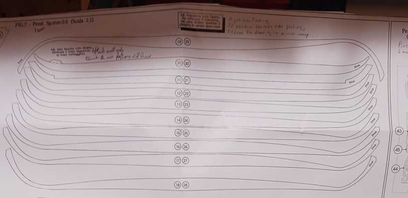
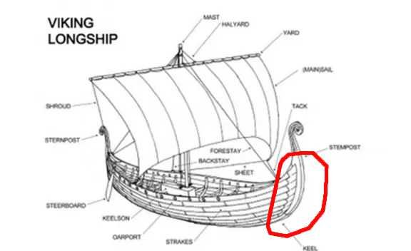
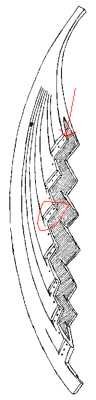
What I mean by tunnel vision in this situation is to focus on building Roar Ege as close to the way that Billing as designed it. I think that any time and effort spent on trying to augment or add realism would be better spent on a later project. A time tested, perhaps THE time tested, path into scratch building is to augment a kit with more sophisticated elements. I think that this particular kit has too much that is too far from real. It would be like starting in a deep hole. In preparation for composing what is real (or at least my admitted limited knowledge of what is real in Viking practice), I scanned all of the Viking kit build logs. Which are authentic looking? At least as far as the hull and the planking - which is pretty much my area of focus. Realistic seems to be Marine Models Dragon class solid carved, Dusek Gokstad, Dusek Knarr, Artesania Latina long boat. The sheer of all is sort of flat. Anything but realistic Billing Oseberg, Roar Ege, and Amati Drakkar. I thought that the impossible planking of Amati: and Roar Ege, which is a bit less cartoon - and pointing out that the planking was freed from Oak trunks/balks using a maul and wedges - I don't see how an individual smith could fabricate a saw. For your kit, the green box is the plank that this plank would have to be spilled from: That these extreme - probably for show - stem and stern were large carved timbers - not actual planks: And these two links are from logs here: https://modelshipworld.com/topic/29710-skuldelev-wreck-3-viking-knarr-by-antyronnen-billing-boats-120/ post 4 pic 4 https://modelshipworld.com/topic/20332-viking-longship-by-binho-dusek-scale-172-model-based-on-the-11th-century-skuldelev-2-wreck/ post 1 pic 4 That the planks had lands in the carved piece: Then I realized that the kits with these extreme curves on their planking were never intended to be realistic. It is a cynical method to avoid having to deal with providing the proper stemson and sternson. At least for Roar Ege, I think that the planks are far too wide. The extreme twist that includes countervailing directions for the kit planking at each end is something that I see as being a frustrating combat for a builder. Being totally outside my Universe, I am not qualified to rule on which short cuts are acceptable in a kit. Oh, about one of my POB terminology complaints - on most POB ships, the central spine fills the midline of the whole hull. Usually it reaches up to the lowest deck being included in the model. For Roar Ege, that part may only be as much as the actual keel. In this situation naming it "keel" would be correct. The possible horrible part would be if it is plywood, with end grain showing where it should not be. 😉 This is meant to be fun. Even if we were part of a university naval architecture department/museum and hair splitting stroum und drang - actual models are no longer in favor. Those decisions seem to be in the control of individuals who have the equivalent of a life long continuous release LSD depot somewhere in their body.

- 145 replies
-
- 5
-

-
-
- Roar Ege
- Billing Boats
- (and 2 more)