Rick01
-
Posts
652 -
Joined
-
Last visited
Content Type
Profiles
Forums
Gallery
Events
Everything posted by Rick01
-
I understand that the jackyard would not appear unless the topsail was being set, however I assume that at least some running rigging would be attached to the topmast at all times, specifically a halyard running through a block at the top of the mast. My question is - when not in use how is this halyard secured? Is it hooked to an eye bolt on the upper mast cap or run down to the deck and secured similarly there (this would entail a hell of a lot of excess rope 2 x total masts height). Sorry if I'm not using correct terminology but I'm still learning. http://www.acmssearch.sl.nsw.gov.au/search/itemLargeCopyright.cgi?itemID=921633&size=full&album=1&collection=823393&parent=442570 Rick
-
Having just finished a build of this model I can add a comment for others - page 13 of this build mentions that there is a problem with bulwarks/ bow " I have added my cap rails and extensions.. I am a bit dissapointed my keel at bow seems to have fallen a bit short of where it should be.. Stern could be a bit higher above rails also. I dont know how that happened,". I had exactly the same problem and brought it up with the manufacturer, basically was told it was my fault even though I'd followed the instruction sheet as well as possible. So I went back to basics and rechecked all my work and still couldn't see where I'd gone wrong. Final ting was to check measurements - low and behold - there is a 2mm difference in height one end to the other for the bulwarks and although the fit appears better with the high end to the bows it should in fact have the lower end to the bows thus allowing the extra room in the bow keel for the required drill holes. The instructions just say "identify and fit" no mention of the 2mm difference - I did point this out to the manufacturer and was told that they'd fix this in their next review. Rick
-
Regretfully, if the Brig Mermaid is any guide then the ship's boats will be plastic and the keel stem and stern posts ply needing to be "planked". Rick
-
Love to Brian but I'm afraid my night driving days (bad joke here) are over at the moment. Come daylight saving I'll have to look at a visit as I'm pretty sure I'll still have questions at that point. Rick
-
Thanks for the illustration Brian - with that and a number of other pictures I've found I've been able to work out ratios of side to width to height. However I haven't been able to find any measurements for a full size one that I can scale down. I realize that they'll vary but I'm guessing that the cabinet would stand between 900 and 1200 mm high. Can anyone confirm this for me. I can scale it down to 1/48th easily from there. Thanks Rick
-
Thanks guys - I should have had a little more faith in my own instincts. I had thought of a binnacle cabinet but wondered as she was such a small ship. I'll start a search here for examples and should be able to dummy something up without too much trouble. Rick
-
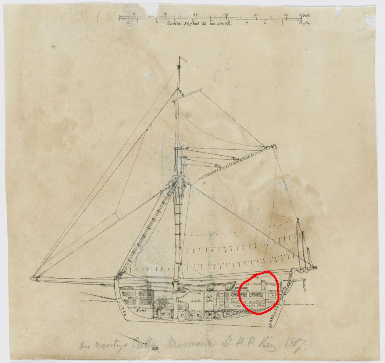
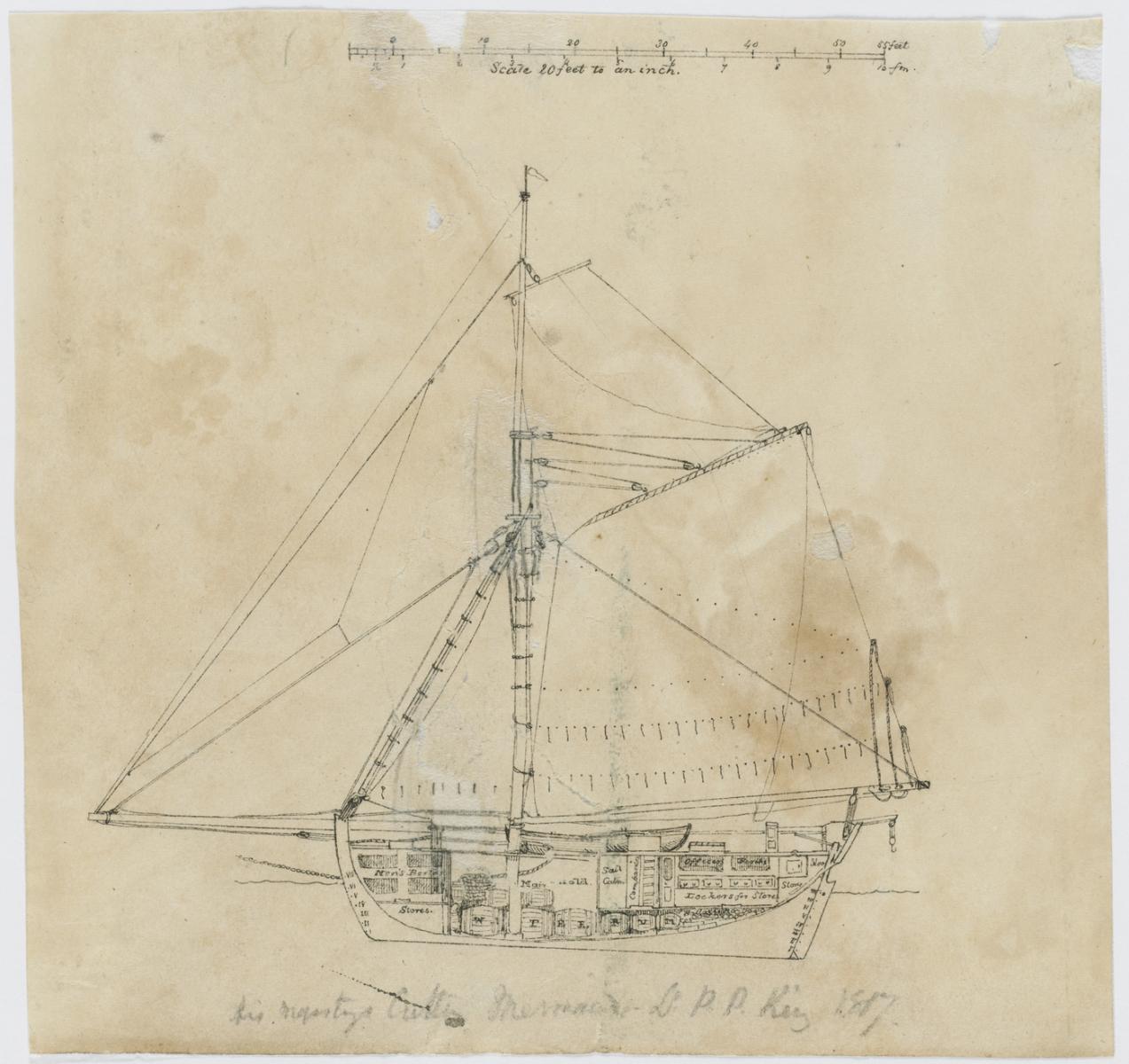
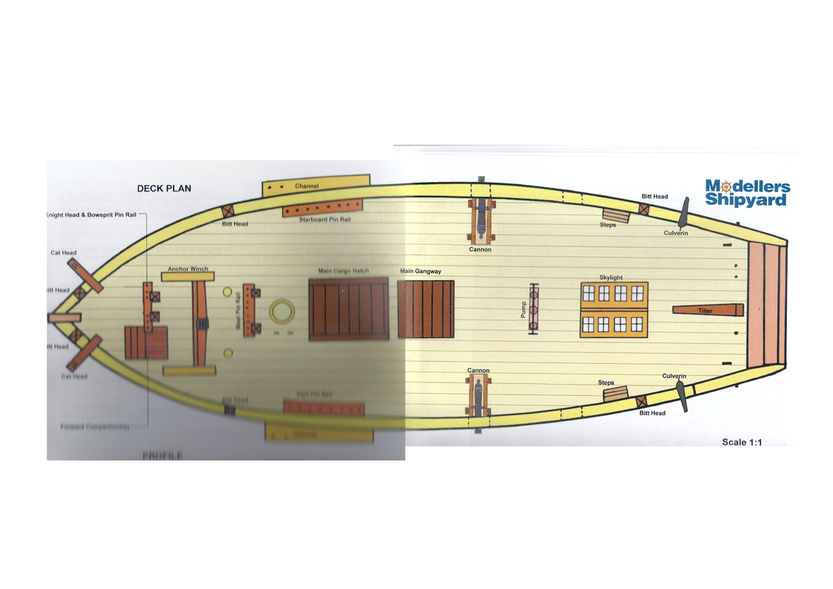
Can anyone help with identifying the item on deck just forward of the tiller please. The cutter was an 84 ton cutter built of teak in Calcutta, commissioned in 1817 and used to explore and survey the Australian coast. The kit makes no mention of this and I haven't been able to identify it with my (very) limited knowledge. Thanks in advance. As a matter of interest the bilge pumps don't appear in this sketch and the throat halliard and topping lift both seem to be running through blocks attached to or below the lower mast cap. This appears contrary to Lennarth Petersson's book and the kit instructions. Rick

-
HM Mermaid Rigging questions (edited by admin)
Rick01 replied to Rick01's topic in Masting, rigging and sails
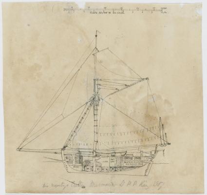
Now starting to rig the mast and spar and further questions have come up. Footrope stirrups - no length has been given for these - I'd guess that they should be scale equivalent of around 850 mm to allow feet on the rope and waist on the spar. Can anyone confirm/comment. Additionally as I'm using King's sketches which clearly show no topsail yard how/where do I attach cluelines and sheets? Rick -
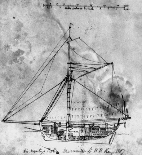
Here's a sketch by King - clearly shows the spreader bracing the top mast. I've ordered a copy of the book and expect to have to make some sort of allowance for the size difference - length 56ft beam 18ft 6 in. but I will at least get a better idea of the way the rigging works as some is not that clear on contemporary sketches. Thanks again. Rick
-
Thanks guys - the sketch makes sense and of course means more work for me! The supplied mast cap doesn't have enough depth to allow for a channel so it's off to the workshop and machine another one. I would think that the ringbolt would allow the spreader to be lowered easily for repairs, replacement etc. and the other square marks should be some sort of locator pegs. Off to buy a copy of Ienneth's book now before I get any more confused. Rick
-
I'm now at the point of assembling the masts, spars and booms but notice that King's illustration has a number of differences in rigging to that supplied with the instructions. Most obvious being 2 blocks between the mast caps (per King) and 4 per instructions. I can work out the basic run of the rigging fairly well from King's sketches however I'm wondering if there is a fairly straight forward book out there somewhere which will help me understand what's going on. I'm guessing that whilst the rig is basically the same on cutters there will be some variance in mounting and number of blocks used dependant on the size of the cutter. One other query - how is a topmast spreader attached to the mast cap? Again instructions are not to clear " identify ... fit and fix ... across the top of the lower mast cap" doesn't tell me a lot. Thanks Rick
-
Thanks John - what I expected but needed confirmation. Rick
-
Can anyone please help regards to mounting the bowsprit. The instructions indicate that the inboard end of the bowsprit sits on top of the pinrail between the knight heads, however there is no indication as to how it is secured at this point. I understand that there would be an eyeglass (?) fitting holding it at the stem post but are there additional lashings/bolts securing it at the point of the knight heads? Thanks Rick
-
Thanks - I hadn't picked up on that set of photos. Rick
-
Thanks - next stop my library I think. :-) Rick
-
So it would be normal with a cutter built to naval specs to have this area boarded in? As you may have Guessed my knowledge of ship construction is near zero so I'm using contemporary models plus King's own illustrations of the Mermaid to build my model and the more I do the more it seems the kit instructions have deviated from what would be correct. Rick
-
Next question whilst I'm working on the deck area of my model. This section of Ollie's build shows a series of "frames" as required by the plans http://modelshipworld.com/index.php/topic/3958-hm-colonial-cutter-mermaid-by-ollie-modellers-shipyard/page-16?hl=mermaidMy problem here is that all the models I've looked at of cutters built during the same 1800 period in the UK NMM do not show these frames. Who's correct? Not from NMM but a good clear shot anyway http://www.modelships.de/Museums_and_replicas/Science_Museum_London/gIMG_0584.jpg Rick
-
HM Mermaid Rigging questions (edited by admin)
Rick01 replied to Rick01's topic in Masting, rigging and sails
Thanks again - as my knowledge of ships is limited to port, starboard, bow and stern your advice has been very helpful. Rick -
Wayne - thanks for the high res. shot. It has helped answer my queries. For some reason I'd not found that particular link when looking for information. Rick
-
I've already got a query going in the rigging section but now have a point to clarify re fixtures and fittings. I'm basing everything on the sketches by King rather than Modellers Shipyard plans as these appear to be lacking in accuracy in some areas. In this sketch from left to right we appear to have a forward companionway, pinrail, windlass tight up against pinrail and then possibly ship's oven. Behind the mainmast is the main cargo hatch, gangway, sky light with the ship's boat stored behind, then lastly possibly the pump. The plans however seem to have gained a "main pinrail" unless it's hard up against the mainmast in King's sketch, reversed the pump and skylight and removed the ship's oven. I understand the oven is moveable so that's not of concern however any comments on these points would be appreciated. Rick


-
HM Mermaid Rigging questions (edited by admin)
Rick01 replied to Rick01's topic in Masting, rigging and sails
Thanks for the picture - better than the one I have. It has raised another couple of questions however. First the oven would appear to be exactly where the anchor windlass should be situated and second the anchor attachment would appear to be chain not rope. Any one like to comment, particularly over the windlass situation. Rick -
HM Mermaid Rigging questions (edited by admin)
Rick01 replied to Rick01's topic in Masting, rigging and sails
Not exactly something King would get wrong is it. Looks like I'll be making some VERY small hooks later in the build and I had no intention of kit bashing this early in my career. I thought it may be a stove but didn't realise they were "mobile" so looks like an Aussie BBQ isn't anything new. Rick -
HM Mermaid Rigging questions (edited by admin)
Rick01 replied to Rick01's topic in Masting, rigging and sails
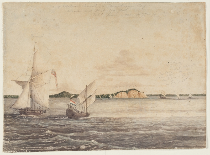
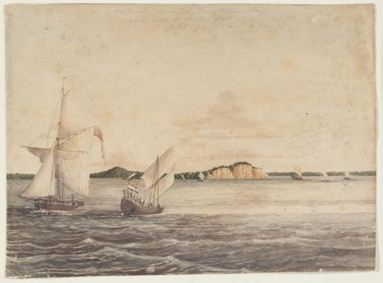
This watercolour seems to show hooks on the second and third visible blocks counting from the left. Blowing it up in Photoshop makes them appear quite clearly as a hook shape below the block. Just as a matter of interest this also shows something looking like an F1 air intake reversed on top of the anchor winch! Pittwater News has the best copy see http://www.pittwateronlinenews.com/bungaree-was-flamboyant-by-neil-evers.php Rick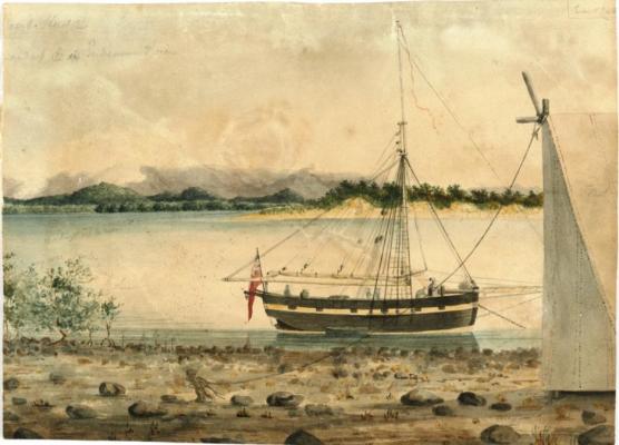
-
HM Mermaid Rigging questions (edited by admin)
Rick01 replied to Rick01's topic in Masting, rigging and sails
I'm basically working off those for details of rigging etc. rather than the plan booklet supplied. I also noticed that the blocks controlling the upper boom/gaff? seem to attach via hooks rather than having been bound to it. In this case the eyelets that they attach to would either have been bound to the gaff or bolted through it at a guess. I wouldn't have thought the latter however as that would seem to weaken it quite considerably. Rick -
HM Mermaid Rigging questions (edited by admin)
Rick01 replied to Rick01's topic in Masting, rigging and sails
OK next rigging query (and unless it's a problem I'll keep any rigging type queries going on this thread). The mainsail attaches to the mainmast via a number of large metal rings, when the sail is removed I assume that the rings stay on the mast, so if I complete my model under bare masts I assume that to be somewhere near correct these rings should still be apparent sitting on the yoke that connects the boom to the mast (excuse the terminology if it's incorrect). I'm nowhere near this stage yet but I prefer to have an idea of what I'm doing well before I get there and find I've got to tear something down because I forgot to ask the question. Rick