Rick01
-
Posts
652 -
Joined
-
Last visited
Content Type
Profiles
Forums
Gallery
Events
Everything posted by Rick01
-
I actually re-rigged it recently following more closely Chuck's longboat in the area of the stays for each mast using dead eyes instead of tying the stays directly to eye bolts as the instructions show. Rick
- 6 replies
-
- 1
-

-
- artesania latina
- longboat
- (and 2 more)
-
This may help a little http://modelshipworld.com/index.php/topic/8158-hms-endeavours-longboat-rick01-al-160/. It's my first build and I agree the rigging instructions aren't very helpful but a bit of research will clarify things a bit. The builds here should also help with rigging http://modelshipworld.com/index.php/forum/51-msw-group-build-of-an-18th-century-longboat/. Rick
- 6 replies
-
- 1
-
-
- artesania latina
- longboat
- (and 2 more)
-
Help in Identifying an Unknown Tool
Rick01 replied to BANYAN's topic in Modeling tools and Workshop Equipment
It scribes parallel lines but is missing a block. There's a couple of pictures here https://www.etsy.com/listing/64392965/antique-brass-wood-carpenter-scribe-tool. Set the two pins for the distance apart for the lines then set the block for distance from the edge of the wood. Especially useful for mortice and tenon joints. Rick -
"Lady Nelson" pin rails.
Rick01 replied to Rick01's topic in Building, Framing, Planking and plating a ships hull and deck
Tried them and they follow the painting and Tassie replica. Both of these seem to be based on an engraving published in England in 1803 purporting to show her in the Thames. Problem is that she was here in Aus. at that time - interesting point with the engraving is that it appears to have her showing scrambling netting set and personally I can't think of anyone liable to want to board her there! See Wikipedia illustration https://upload.wikimedia.org/wikipedia/commons/a/ab/His_Majesty%27s_vessel_the_Lady_Nelson_-_1799.JPG Rick -
I'm at the stage of mast assembly and rigging and need some advice on pin rails. As you will see there are no gunwales and so no points to attach rails securely ( the rail running round the hull is only approx 25~30 cm high in full scale. Rigged as a brig there wouldn't be much room for all the cleats needed on the masts themselves. Any assistance/comments/links to help would be greatly appreciated. Thanks Rick
-
Maybe look at a No. 3 scalpel handle with No. 11 blades plus a good supply of rubber bands. Rick
-
Thanks guys - Mark after a little thought and more examination of the original model (via the photos) your idea has more merit than my first thought. Fixing through the beams would cause the gun to buck on recoil as the pressures would not be in a straight line through the centre of the gun carriage (if that makes sense). Pat - I've studied various photos of the replica and see that the companionway has no glass which does make sense - however as there are a number of other features which do not follow the original model and the plans available from Float-a-boat in Melb were based on discussions with the Tassie people (again no glass - but companionway and skylight as a single unit) I thought I'd try for a third (or more) opinion. It was the paint job replicating glass that has thrown me. However no glass makes more sense than glass so I think I'll go that way. Rick
-
Anyone? Not even a guess? Rick
-
I'm slowly attempting to bash a kit into the Lady Nelson using the Royal Museums Greenwich as my base model. http://collections.rmg.co.uk/collections/objects/66562.htmlI've arrived at a point where I need to clarify a couple of items - firstly whilst the skylight is obviously glassed in the companionway side is solid but appears to be painted as if to resemble glass. Do I glaze or not? Second item - she carried 6 guns and on the way out from England these were described as 3~4 lb brass carriage guns - this info. from various log entries (not carronades as may have been swapped in later). Given that there are no gunwales would they have been secured with ringbolts through the deck (answer seems yes but I'm just checking :-) ). For locals seeing this post - I've seen and have copies of the Float-a-boat plans, these however do deviate from the original model layout and the various paintings/engravings out there all seem to be copies of the original of her in the Thames. This however is problematical as it was published in 1803 when she had already been in in Aus for some time. Rick
-
Crows nest/cross trees 18th Century Brig
Rick01 replied to Rick01's topic in Masting, rigging and sails
OK now I understand it better, I read Allan's post before having my morning coffee!!! The Lady Nelson plan also helps and that together with a search of the forum for pictures of these on other brigs of the same period have pretty well solved my problem. Thanks guys Rick -
Crows nest/cross trees 18th Century Brig
Rick01 replied to Rick01's topic in Masting, rigging and sails
Sorry Allan - badly worded request on my part. :-( I was actually asking about the crows nest/cross trees themselves. Masts are sorted and the brig was built in the UK in 1799 and then sailed to Aus in 1800. Rick -
I'm slowly bashing a cutter into the Australian Brig "Lady Nelson" and am currently working on the masts. Is there a formula (or set of dimensions) that set the size of of these. Side views obviously only give me the length but no clues as to widths. Rick
-
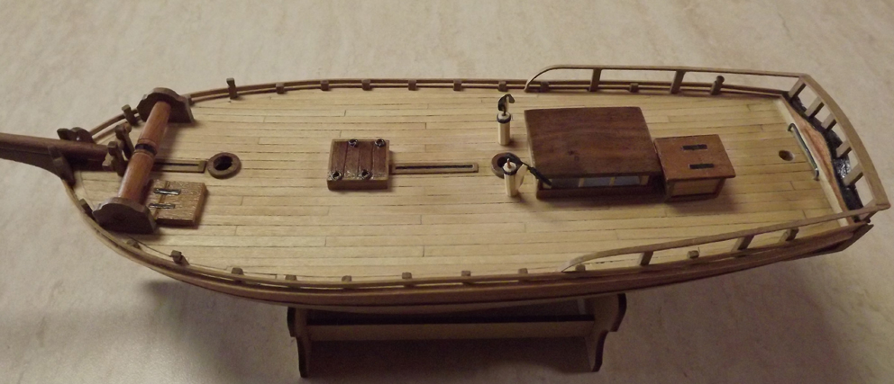
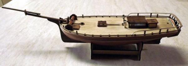
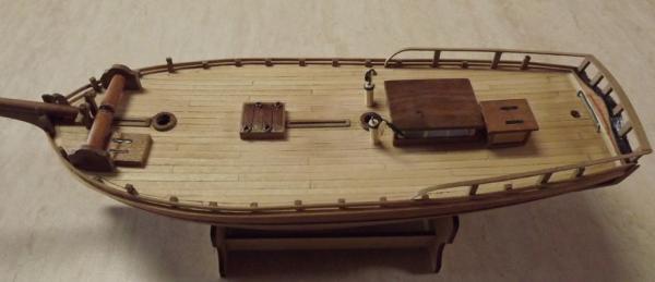
Here's my finished product http://modelshipworld.com/index.php/gallery/member/15284-rick01/ -a little different to the kit but not hard to achieve. Main differences being rigging and position of deck furnishings. Yell if you want to talk about any of it. I'm only a first time builder but happy to help if I can. Rick
-
For lack of any other reply I should add that I used a three plank pattern with the planks being 120mm long which visually seemed OK. Rick
-
If you search "Mermaid" you'l find a couple of builds plus a few queries that I've made regarding accuracy (or not) of the plans supplied. Before you fit the bulwarks be very careful as two of us have had a problem here which I later solved - "there is a 2mm difference in height one end to the other for the bulwarks and although the fit appears better with the high end to the bows it should in fact have the lower end to the bows thus allowing the extra room in the bow keel for the required drill holes. The instructions just say "identify and fit" no mention of the 2mm difference - I did point this out to the manufacturer and was told that they'd fix this in their next review." Rick
-
Tadeusz, thanks for your answer re shrouds and the reference book "Historic Ship Models" by Wolfram zu Mondfeld. This will help me immensely. Rick
-
Is there a rule/formula to give the number of shrouds required for any given mast? I'm looking at illustrations of HM Lady Nelson and a contemporaneous model on NMM clearly shows five including a possible backstay whilst an engraving at about the same period seems to indicate seven with possible backstays included. Rick
-
Thanks again Brian - if/when I start I'll give you a heads-up. Rick
- 57 replies
-
- 1
-
-
- Lady Nelson
- Victory Models
- (and 2 more)
-
Lady Nelson
Rick01 replied to Rick01's topic in Discussion for a Ship's Deck Furniture, Guns, boats and other Fittings
Hi John - yes I was aware how different she was having seen both the engraving and the contemporary hull model in the NMM. I'm off to Float-a-Boat next week so I'll have a look at their plans then. I'll just have to assume that the cannons referred to were the equivalent of 3 lb'ers. Interestingly the NMM model has a railing fore and aft rather than the full bulwarks shown on the engraving - wonder which was correct as the model is of her as fitted for the Aus. voyage. Rick -
I'm about to start an attempt to lightly bash the Amati "Lady Nelson" into the Australian "Lady Nelson". NMM have a good contemporary model of the hull http://collections.rmg.co.uk/collections/objects/66562.htmland I have copies of the plans used to build one of the replicas. I'm starting to research the fittings and need a little help with the cannons - her log book states that she was fitted with "2 brass carriage guns" with a further 4 added before she sailed for Aus. No mention of size however - I'm guessing that as she was an exploration vessel they would have been 3~4 lb cannon. Can anyone comment here giving me an idea of the relevant dimensions of them and how they would have been mounted as the model shows a low railing rather than a heavier bulwark to which they could have been braced. Thanks in advance Rick
-
One last question - was the "depth" measured including gunwales? If so can you give me the depth of the gunwales please. The other measurements are actually near as damn it correct for the Australian Lady Nelson if modelled at 1/54 so bashing may not be that hard given how close the hull appears. Rick
- 57 replies
-
- 1
-
-
- Lady Nelson
- Victory Models
- (and 2 more)
-
Thanks Brian - it looks as if the model is actually slightly larger that the Australian ship which at 1/64 would measure 26 cm length and 8.45 cm beam. This is an idea that I'm working on slowly but I don't think it's insurmountable. Rick
- 57 replies
-
- 1
-
-
- Lady Nelson
- Victory Models
- (and 2 more)
-
Hi Brian - I'm contemplating building the Australian "Lady Nelson" which is a two masted brig (cutter conversion per NMM). To see if this kit is readily usable as a base I wonder if you could give me the actual dimensions of the kit hull i.e. length, beam and depth. I've the figures for the original and just need to see how much work is needed to fiddle with the hull. Thanks in advance. Rick
-
HM Mermaid jackyard set flying with the gaff topsail
Rick01 replied to Rick01's topic in Masting, rigging and sails
Looking at the sketch again and in particular the slack line you have noted, is this a possibility? The line is fixed at the gaff peak and runs up and through a block on the yard then down to the deck, when she changes tack the line is then hauled in causing the peak of the yard to drop sufficiently to swing the whole assembly round the mast before being loosened again. This would then explain why it appears without tension in the sketch. Rick -
HM Mermaid jackyard set flying with the gaff topsail
Rick01 replied to Rick01's topic in Masting, rigging and sails
It's even more confusing for an absolute amateur! The "artist" was actually the captain who sailed this cutter around Australia for about 4 years and would have known his ship pretty well one would expect. However as I am rigging the model without sails my main concern is with the lifting rigging. Both the illustration I have provided and another sketch of her actually under sail seem to indicate that the lower corner of the sail is actually attached (via a loop possibly) to the peak of the gaff. If so then no block on the gaff, as King seems accurate with his rigging/blocks etc. in other respects I had assumed that the sail was attatched to and hoist with the gaff. The Mermaid was only a small cutter 17 metres stem to stern, beam 5.6 metres and weighing in at 84 ton. Rick