


NMBROOK
-
Posts
2,305 -
Joined
-
Last visited
Reputation Activity
-

 NMBROOK got a reaction from Ferit in MORDAUNT 1681 by NMBROOK - Euromodel - 1:60 - Beyond Bashed
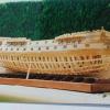
A small,but possibly useful update Work has stopped on my deck 'treenailing' as I have now been waiting a week for some more drillbits to arrive
I have decided to start producing the deck clamps 'in the rough'.These are made from 3mm thick pear sheet and spiled,profiled and prebent where necessary to conform to the inside of the hull.This is not helped by the fact that the tumblehome changes direction right in the middle of these pieces.My plan is to make and bend the sections overlength and add the hooked scarph joints to the ends a little later.
I have started at the bow,a paper template was made for the shape and pieces cut to suit oversize in height and length.The top edge cannot be accurately established until the deck beams are dry fitted and the hull cutouts used as a reference.The angle of cut of the top edge also changes massively at the bow as the profile is in effect twisted.
I soaked the piece to be bent for three hours in water,then this was placed in the kettle and boiled up.The strip was first worked in my fingers to ease the bending process.The strip was then clamped to the inside of the hull and left for 3 days!!!!.Upon removal absolutely no spring back was experienced.The final job for now was to dish the matting face to suit the tumblehome.
The second one is now clamped in place and is resting for it's 3 days I will continue with something else for the rest of the weekend
Kind Regards
Nigel
-
 NMBROOK got a reaction from tarbrush in MORDAUNT 1681 by NMBROOK - Euromodel - 1:60 - Beyond Bashed
A small,but possibly useful update Work has stopped on my deck 'treenailing' as I have now been waiting a week for some more drillbits to arrive
I have decided to start producing the deck clamps 'in the rough'.These are made from 3mm thick pear sheet and spiled,profiled and prebent where necessary to conform to the inside of the hull.This is not helped by the fact that the tumblehome changes direction right in the middle of these pieces.My plan is to make and bend the sections overlength and add the hooked scarph joints to the ends a little later.
I have started at the bow,a paper template was made for the shape and pieces cut to suit oversize in height and length.The top edge cannot be accurately established until the deck beams are dry fitted and the hull cutouts used as a reference.The angle of cut of the top edge also changes massively at the bow as the profile is in effect twisted.
I soaked the piece to be bent for three hours in water,then this was placed in the kettle and boiled up.The strip was first worked in my fingers to ease the bending process.The strip was then clamped to the inside of the hull and left for 3 days!!!!.Upon removal absolutely no spring back was experienced.The final job for now was to dish the matting face to suit the tumblehome.
The second one is now clamped in place and is resting for it's 3 days I will continue with something else for the rest of the weekend
Kind Regards
Nigel
-
 NMBROOK got a reaction from mij in MORDAUNT 1681 by NMBROOK - Euromodel - 1:60 - Beyond Bashed
A small,but possibly useful update Work has stopped on my deck 'treenailing' as I have now been waiting a week for some more drillbits to arrive
I have decided to start producing the deck clamps 'in the rough'.These are made from 3mm thick pear sheet and spiled,profiled and prebent where necessary to conform to the inside of the hull.This is not helped by the fact that the tumblehome changes direction right in the middle of these pieces.My plan is to make and bend the sections overlength and add the hooked scarph joints to the ends a little later.
I have started at the bow,a paper template was made for the shape and pieces cut to suit oversize in height and length.The top edge cannot be accurately established until the deck beams are dry fitted and the hull cutouts used as a reference.The angle of cut of the top edge also changes massively at the bow as the profile is in effect twisted.
I soaked the piece to be bent for three hours in water,then this was placed in the kettle and boiled up.The strip was first worked in my fingers to ease the bending process.The strip was then clamped to the inside of the hull and left for 3 days!!!!.Upon removal absolutely no spring back was experienced.The final job for now was to dish the matting face to suit the tumblehome.
The second one is now clamped in place and is resting for it's 3 days I will continue with something else for the rest of the weekend
Kind Regards
Nigel
-
 NMBROOK got a reaction from Kevin in MORDAUNT 1681 by NMBROOK - Euromodel - 1:60 - Beyond Bashed
A small,but possibly useful update Work has stopped on my deck 'treenailing' as I have now been waiting a week for some more drillbits to arrive
I have decided to start producing the deck clamps 'in the rough'.These are made from 3mm thick pear sheet and spiled,profiled and prebent where necessary to conform to the inside of the hull.This is not helped by the fact that the tumblehome changes direction right in the middle of these pieces.My plan is to make and bend the sections overlength and add the hooked scarph joints to the ends a little later.
I have started at the bow,a paper template was made for the shape and pieces cut to suit oversize in height and length.The top edge cannot be accurately established until the deck beams are dry fitted and the hull cutouts used as a reference.The angle of cut of the top edge also changes massively at the bow as the profile is in effect twisted.
I soaked the piece to be bent for three hours in water,then this was placed in the kettle and boiled up.The strip was first worked in my fingers to ease the bending process.The strip was then clamped to the inside of the hull and left for 3 days!!!!.Upon removal absolutely no spring back was experienced.The final job for now was to dish the matting face to suit the tumblehome.
The second one is now clamped in place and is resting for it's 3 days I will continue with something else for the rest of the weekend
Kind Regards
Nigel
-
 NMBROOK got a reaction from md1400cs in MORDAUNT 1681 by NMBROOK - Euromodel - 1:60 - Beyond Bashed
A small,but possibly useful update Work has stopped on my deck 'treenailing' as I have now been waiting a week for some more drillbits to arrive
I have decided to start producing the deck clamps 'in the rough'.These are made from 3mm thick pear sheet and spiled,profiled and prebent where necessary to conform to the inside of the hull.This is not helped by the fact that the tumblehome changes direction right in the middle of these pieces.My plan is to make and bend the sections overlength and add the hooked scarph joints to the ends a little later.
I have started at the bow,a paper template was made for the shape and pieces cut to suit oversize in height and length.The top edge cannot be accurately established until the deck beams are dry fitted and the hull cutouts used as a reference.The angle of cut of the top edge also changes massively at the bow as the profile is in effect twisted.
I soaked the piece to be bent for three hours in water,then this was placed in the kettle and boiled up.The strip was first worked in my fingers to ease the bending process.The strip was then clamped to the inside of the hull and left for 3 days!!!!.Upon removal absolutely no spring back was experienced.The final job for now was to dish the matting face to suit the tumblehome.
The second one is now clamped in place and is resting for it's 3 days I will continue with something else for the rest of the weekend
Kind Regards
Nigel
-
 NMBROOK got a reaction from janos in MORDAUNT 1681 by NMBROOK - Euromodel - 1:60 - Beyond Bashed
A small,but possibly useful update Work has stopped on my deck 'treenailing' as I have now been waiting a week for some more drillbits to arrive
I have decided to start producing the deck clamps 'in the rough'.These are made from 3mm thick pear sheet and spiled,profiled and prebent where necessary to conform to the inside of the hull.This is not helped by the fact that the tumblehome changes direction right in the middle of these pieces.My plan is to make and bend the sections overlength and add the hooked scarph joints to the ends a little later.
I have started at the bow,a paper template was made for the shape and pieces cut to suit oversize in height and length.The top edge cannot be accurately established until the deck beams are dry fitted and the hull cutouts used as a reference.The angle of cut of the top edge also changes massively at the bow as the profile is in effect twisted.
I soaked the piece to be bent for three hours in water,then this was placed in the kettle and boiled up.The strip was first worked in my fingers to ease the bending process.The strip was then clamped to the inside of the hull and left for 3 days!!!!.Upon removal absolutely no spring back was experienced.The final job for now was to dish the matting face to suit the tumblehome.
The second one is now clamped in place and is resting for it's 3 days I will continue with something else for the rest of the weekend
Kind Regards
Nigel
-
 NMBROOK reacted to shihawk in HMS Victory by shihawk - FINISHED - Billing Boats - 1:75
Quick couple of pics to show finished stern gallaries I think the brass looks alright , i can,t even begin to think how some of you guys can paint such fine detail , it would be completely beyond me .
I think it,s the T that is slightly off ??
-
NMBROOK reacted to rafine in Frigate Essex by Rafine - FINISHED - Model Shipways - Kitbashed
Work on the lower masts is now basically complete. The mizzen lower mast and it's top have been made and mounted. This was a simpler job than the fore and main because the mizzen does not have extended cheeks or a front fish. There are also no metal bands except at the head and only one woolding just below the bibbs. The only additional item is the rest for the driver boom which was cut from boxwood sheet with boxwood strip supports. There are some blocks which will be added to the mast head when they arrive ( i stupidly forgot to order all of the sizes I needed when I placed my first order for blocks).
With the completion of this work, I am starting work on the lower deadeyes and chains and then the hammock cranes and netting. It's very possible that the tedium of doing all those deadeyes and chains will cause me to go back and forth between the two .
Bob
-
NMBROOK reacted to rafine in Frigate Essex by Rafine - FINISHED - Model Shipways - Kitbashed
I've now completed and mounted the main lower mast. The procedure was identical to what I showed for the fore mast , with the exception that there are no blocks hung from the top or seized to the masthead and there is a deadeye seized to the lower part of the mast for the mizzen stay.
I'm now working on the lower mizzen mast.
Bob
-
NMBROOK reacted to jaerschen in HMS Leopard 1790 by jaerschen - 1/64 - POB - 50 gun ship
Thank you for your kind words Nigel. Now I looked to your builds and must say that you are doing also a great job.
@Ed
You are absolutely right. There are so many to read, I can't up my mind what to read at next
-
NMBROOK reacted to tarbrush in Mary Rose 1545 by tarbrush - Scale 1:72
thanks Nigel, I hope to not disappoint. I envy your home location, it would be so awesome to be able to go visit Mary Rose during the build.
-
NMBROOK got a reaction from tarbrush in Mary Rose 1545 by tarbrush - Scale 1:72
This is a truly fascinating build John and I am keenly following along I actually found the link for the UK news article covering the forecastle find.Alas,this was a dead link,the Daily Mail newspaper must have removed it
Having visited the vessel prior to getting her new home,the one thing that surprised me was how small she actually was,maybe this is due to seeing Warrior and Victory at the same time.Conditions must have been incredibly cramped on board.
I look forward to seeing more of your great work and following the model's progress.
Kind Regards
Nigel
-
NMBROOK reacted to tarbrush in Mary Rose 1545 by tarbrush - Scale 1:72
Working on the keel stem & sternpost the shortcuts begin right off.
Quoting from Peter Marsden's book Mary Rose Your Noblest Shippe : "The cross section of the keel varies throughout it's length. It's midship portion has an uneven hexagonal shape whereas fore and aft of this it becomes deeper and narrower with rebates for stealer planks cut into the upper part of it's sides".
hmmmmm.... ok, at the bow and stern it is rectangular as you move amidships it becomes hexagonal in shape that changes over the length of the keel. Well, Chidoken did it for his cross section.
I thought about it overnight. Not whether I would try it, but if I should switch to something easier. That made my eyes go crossed just reading the description. I knew I didn't want to try that.
By the next morning I decided that as I am modeling the whole ship the keel shape isn't going to be that noticeable a detail for the amount of effort it was going to require and I made the keel assembly as would on any other model.
Next up are the frames.
Although there is a great deal of information on Mary Rose there are still many questions. After reading through the information I had I am still not entirely sure of the framing arrangement. So rather then display the framing by leaving one side unplanked I will just have viewing ports on one side to enable the interior to be seen and leave off strips of ceiling
so that the framing is an interesting bit of detail behind the ceiling planks.
OK, to get started with the framing.
The plans showed the frames to be fairly evenly sided and spaced.
But on drawing on page 105 of Mary Rose Your Noblest Shippe show something far different. I will use this drawing as the basis for my frames sided dimensions and location, of course forward and aft of the diagram will just be a guess.
Mary Rose's framing was unique for a vessel of her time. An article I found online gave a good explanation of this.
The Structures of Atlantic Shipbuilding in the 16th Century, by Brad Lowen:
"In the case of the Mary Rose, the concept of tying each frame timber to a specific element in the frames design had become impracticable because the arcs were too long for the available timber supply. In particular, long enough first futtocks could not be found to cover the bilge arc, the futtock arc and overlap with the clamps at the first deck. The solution adopted by the builders was in some ways a precursor to the double-sawn frame. Instead of overlapping the the floor timber and the first futtock, these pieces were laid end-to-end, and a second timber laid between the frames in order to reinforce the area of the end-to-end joint".
This illustration from Marsden's book shows this and the hexagonal keel.
So far I have sawn and sanded several of the midship frames and most of the frame blanks for the rest of the hull, haven't begun to glue any on yet though.
-
NMBROOK reacted to jaerschen in HMS Leopard 1790 by jaerschen - 1/64 - POB - 50 gun ship
The Port Side is at the same progress as the Starboard Side.
I don't make many words because the procedure is the same.
Here some photos of the current progress.
-
NMBROOK reacted to jaerschen in HMS Leopard 1790 by jaerschen - 1/64 - POB - 50 gun ship
Much thanks for the kind comment Timmo.
It's going on with the build. I added two rails during the last days.
But I want to display how make the planks above (or under) the gunports at first.
First step is to mark the position where the plank must be wider
Then I saw the plank with the bandsaw
and sanded it
Thereafter it must be fitted to the other planks. I did that with a chissel. That's the easiest way to do it for me.
Here you can see the result.
And now some photos of the current progress.
-
NMBROOK reacted to jaerschen in HMS Leopard 1790 by jaerschen - 1/64 - POB - 50 gun ship
Thanks very much Alexander.
Slowly but constant. Here's a new update.
I added the Channel Wale and planks between the Main Wale and the Channel Wale.
-
NMBROOK reacted to jaerschen in HMS Leopard 1790 by jaerschen - 1/64 - POB - 50 gun ship
Could you tell me the result please. It's very interesting for me-
And now to the idea from Mark
I sanded the Main Wales about days and following this I used black stain.
How shall I put it?
You are right Mark, it looks mutch better. Thank you, the effort paid off.
In fact it's much better to seen as at the photos.
And also I planked the Lower Counter
-
NMBROOK reacted to jaerschen in HMS Leopard 1790 by jaerschen - 1/64 - POB - 50 gun ship
Hi Niklas and Adam, thanks for the kind words.
It's going on with the Main Wale. I done it in the same manner as John McKay is shown at his plans.
I made two templates at first because I must produce many equal pieces.
Also it must drawn the postion of the Main Wales to the Frames.
Thereafter began the agony
Here's the result
Juergen
-
NMBROOK reacted to jaerschen in HMS Leopard 1790 by jaerschen - 1/64 - POB - 50 gun ship
Hello,
after I put off my Triton build I started a new project. Now I want to build the 50-Gun Ship HMS Leopard 1790 (POB) ,1/64 scale
Therefor I bought the book The 50-Gun Ship from Rif Winfield. At this are the plans of the Leopard drawn by John McKay.
I don’t make many words about the build of the frames because that’s often described here on MSW.
Instead I show some photos.
Juergen
-
NMBROOK reacted to JPett in HMS Victory by JPett - Corel - 1:98
Ahoy Mates
This should be my last post as a Commander
Dragzz: That build is amazing
Scott: It's the edge bending
Lawrence: It just looked odd but its yours to do as you please. The wedges are coming in quite handy on this first planking. Not sure if they will be good on the second
Back to the build
Well planking this beast is sure turning out to be a learning experience. I still can not seem to get my head around belts; that and the edge bending is really getting a little out of hand.
I have completed the port belt and decided to do the Garboard belt next. My hope is that once complete I will be able to better plan the next two belts. I am winging the plank widths. I am going with "they need to taper just before the stern and then flare" as my last model did. So far it looks like I am close and any errors should only cause minor problems. Fingers crossed.
The edge bending has me concerned on all three belts. I am hoping the thinner walnut will be a little more receptive to the curves. The drop plank on the port side had to be done three times. I now have some "franken planks" as a result of my changes. I normally would have just replaced the complete plank but do not know how much extra wood Corel has included. Currently my waste is less then one strip. Possible only a half.
In the stern my planks do not line up on both sides and I will have to pay better attention to this with the walnut. I am debating whether to make a correction on this or not. On the bow I had to pull back my drop plank due to all my mistakes and there were quite a few. I was happy with the way it turned out until I saw this picture. I see I have one more issue to address. I am hoping all this experience will only help me on the final planking. Trust me when i say the thought of just slapping all these on and then throwing a sanding party; then inviting some filler is entertained quite frequently in the shipyard.
The bow end of the garboard plank was much easier then I thought. I just terminated it at bulkhead 2. Any further and it was curving up which I was told is something this plank should never do. I have some doubts as to how much and how I tapered the following planks as this led to considerable edge bending to get compliance. I went slightly wider on the last plank to hopefully reduce it for the ones that follow. If I were to do this again I would put a filler here.
In the stern getting the planks to conform and contact the plywood keel was not so easy. I found that nuking small pieces of paper towel in a shallow dish of water and then clamping them to the wood very helpful. Getting the wood to make full contact with the plywood keel took no less then five sessions.. Because I believe I will be sanding most of this all the way back down in some areas I felt full contact necessary. Its just which area???, that is why it all needs to be put down. Sanding here, fitting the walnut and the keel post are one of my biggest concerns with this project. I also pulled up the garboard strake where it met the keel post. The plans do not show the planks sweeping up as mine do but I felt that if I matched the plans with this layer I would not be able to with the final one. I did this plank two times before I realized this and then did it another two more times to get this. . I am be big believer in water solvable PVA. it really is a newbies best friend.
-
NMBROOK reacted to archjofo in La Créole 1827 by archjofo - Scale 1/48 - French corvette
Hello colleagues,
thank you for your encouragement.
Lately, I was not very productive. To this end, my scanty results:
Various works: boarding ladders port side, eye bolts with rings for the deck and inboard.
On the port side still had to be mounted the boarding ladders. This I had made some time ago and given to appropriate explanations.
For the open battery deck I made still eye bolts with rings, as well inboard of the gun ports, a total of 60 pieces. Also here is to note again that these differ in the size of the eye bolt on the outboard side.
To be continued ...
-
NMBROOK reacted to Kevin in HMS Triton 1:48 (cross section) by Kevin
good evening everyone
well after the 4th attempt i got it right, well i did on the 3rd as well but cut the 3 length the wrong size
i wanted a darker wood for the false keel so used some from my scrap wood pile
-
NMBROOK reacted to NAZGÛL in Wasan 1628 by Nazgul - FINISHED - Billing Boats Vasa 1:75
Cheers Nigel!
/Matti
-
 NMBROOK got a reaction from NAZGÛL in Wasan 1628 by Nazgul - FINISHED - Billing Boats Vasa 1:75
Excellent work mate!!!!!!
Kind Regards
Nigel
-
NMBROOK reacted to NAZGÛL in Wasan 1628 by Nazgul - FINISHED - Billing Boats Vasa 1:75
Hey all, here is an update finally. I've done the other side of the mainmast and made the portside of the mizzen mast. I found it difficult to imitate the sagging curves of the original, but it was easier on the mizzen as the shrouds are angled straight up. First a reference pic I took at the museum:
/Matti