
MORE HANDBOOKS ARE ON THEIR WAY! We will let you know when they get here.
×


KeithAug
-
Posts
3,867 -
Joined
-
Last visited
Reputation Activity
-

 KeithAug reacted to Julie Mo in Altair 1931 by KeithAug - FINISHED - Scale 1:32 - schooner
That brass strengthening strip really makes a big difference on your rudder, Keith. Very nice touch!
Your metal work is amazing!
-
KeithAug reacted to wyz in Altair 1931 by KeithAug - FINISHED - Scale 1:32 - schooner
Love'n your progress, Keith.
Tom
-
KeithAug reacted to captainbob in Altair 1931 by KeithAug - FINISHED - Scale 1:32 - schooner
Just found your beautiful build of this lovely boat.
Bob
-
 KeithAug got a reaction from aviaamator in Altair 1931 by KeithAug - FINISHED - Scale 1:32 - schooner
I had a go at the hawsepipe today. The complication is the plate as it exits the hull which is oval in form. This could have been tricky and I wanted it to be neat. The solution in the end proved to be simple and quick to make.
I started with a length of .200 inch diameter brass rod. I drilled out the rod on the lathe to the diameter of the hawsepipe. I then measured the angle the hawsepipe made with the hull at its exit point and set up the bar at this angle in the mill.
I then lopped off the end using a slitting saw.
The next operation was to solder the hawsepipe into the brass rod while still set up in the milling vice.
I then indexed the slitting saw down and repeated the cut.
With a bit of buffing the job was done.
-
 KeithAug got a reaction from KORTES in Altair 1931 by KeithAug - FINISHED - Scale 1:32 - schooner
Altair has 7 portholes just above the waterline, 3 port and four starboard. I had a play with 2 designs. In option 1 the window is glued into a recess cut in the front of the porthole. The porthole is cut from solid brass rod of .325 inch diameter. The window is cut from stiff clear plastic using a standard paper hole punch. Option 1 has the advantage that the resulting porthole seems less "heavy" at the rim. The disadvantage is that its hard to disguise the glue and any unevenness in cutting the edge of the window (made from plastic) is also apparent. The result can look a little messy.
In option 2 the window is inserted into the rear of the porthole and held in place by a tube which is also pressed in from the rear. The advantage is no glue and no rough edges - but at the expense of a heavier rim.
I made both types before choosing option 2 (on the left in the picture below). For me the neatness outweighed the heaviness.
The components below are pre-assembly. The tube was pressed in and then sawn off.
The portholes took about 10 minutes each to make - but as the picture shows they need a little cleaning up.
I'm off on my travels now so no more progress for a while.
-
KeithAug got a reaction from KORTES in Altair 1931 by KeithAug - FINISHED - Scale 1:32 - schooner
Julie - you might want to see the rest before stealing anything!
So here is how it developed.
I started to sand the rudder down to its final form but part way through the process I started to feel the larger pieces of mahogany were looking a bit monolithic and hence out of scale. I did like the pin stripes and I think I will bank this for a future date.
So decided to use what I had as the core of the rudder and clad it as I had done with Endeavour.
I started by laying two strips either side of the leading edge. I seemed to have created some sort of bug!!!!!!!
I then laid more strips across the rudder, parallel to the waterline. Another weird creature was born!!!!!!!
27 pieces per side = 54. Plus the 17 core parts = 71 parts in total.
After a lot of sanding..........
The next step is to make and attach the 2 strengthening plates - one either side of the rudder and then buff the rudder with fine sandpaper before painting with poly.
-
KeithAug got a reaction from KORTES in Altair 1931 by KeithAug - FINISHED - Scale 1:32 - schooner
Deck planking complete - but as yet not sanded:-
A quick post this time consisting mainly of photographs.
Yesterday afternoon / evening and earlier today I completed the deck planking the initial photographs show where i started yesterday.
The accurate marking and positioning of the deck edge planks paid dividends and by the time I reach the deck centre line the symmetry was virtually spot on. No doubt an element of luck played its part.
Deck sanding tomorrow...........
-
 KeithAug got a reaction from Nirvana in Altair 1931 by KeithAug - FINISHED - Scale 1:32 - schooner
I had a go at the hawsepipe today. The complication is the plate as it exits the hull which is oval in form. This could have been tricky and I wanted it to be neat. The solution in the end proved to be simple and quick to make.
I started with a length of .200 inch diameter brass rod. I drilled out the rod on the lathe to the diameter of the hawsepipe. I then measured the angle the hawsepipe made with the hull at its exit point and set up the bar at this angle in the mill.
I then lopped off the end using a slitting saw.
The next operation was to solder the hawsepipe into the brass rod while still set up in the milling vice.
I then indexed the slitting saw down and repeated the cut.
With a bit of buffing the job was done.
-
KeithAug got a reaction from KORTES in Altair 1931 by KeithAug - FINISHED - Scale 1:32 - schooner
I though I'd better finish and mount the rudder.
I needed to drill the holes to take the rudder pivot - a more complicated job than might be expected as I will explain.
I started by marking the position of the hole at the back of the keel. I used tape to mark out the angle and get the right distance from the hull (.200 inch).
I carefully drilled an undersized hole by hand, stopping frequently to check the drilling angles (alignment along the axis of the hull as well as parallel to the back of the keel)
I then started to widen out the hole with some miniature square section broaches - a birthday present from the wife.
Finally finishing to size with a round needle file. A bit complicated but the result was a hole that was exactly right in both size and alignment.
Drilling the top pivot hole was done through the lower hole. The drill bit was much too short for this but I stuck the drill bit in a tube to give it the required length.
The pivot was cut from brass tube and the rudder mounted as a test fit - it worked fine.
I then did a bit of brass bashing to create the rudder strengthening strips - they are about 1 inch x 1/8 inch - fastened in place by 4 rivets.
-
 KeithAug got a reaction from Tecko in Altair 1931 by KeithAug - FINISHED - Scale 1:32 - schooner
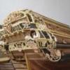
Keel and building board
A bit more progress fitted in around various DIY jobs. I transferred the keel shape to card that I the stuck to the ¼ inch ply before more jigsaw work. See Photos.
I made the building board from ¾ inch thick 6 inch wide MDF. For about 2/3 of the length of the hull the building board is double thickness with the stand off for the frames reduced in height to compensate (reducing plywood wastage). Using my router table I machined slots along the length of the MDF to facilitate:-
1. accurate alignment of the 2 boards
2. location of the frames along the center line
3. location of the board on the milling machine to cut slots for the frames at right angles to the center line.
The frame spacing was accurately measured from the plan and I used the digital read out on the mill to accurately set the positions for the frame sots. None of the frames were equally spaced which was a bit of a bind.
The photos should illustrate the process.
Finally I did a test assembly of the frames to give myself a feeling of progress.
Everything fitting together well and all right angles accurately made .......... feeling very content!
-
KeithAug got a reaction from KORTES in Altair 1931 by KeithAug - FINISHED - Scale 1:32 - schooner
And finally the capping rail is complete and ready for final sanding.
I put the outer edge of the rail in as a series of short lengths - approx 30cm long - 3 per side. This felt easier to manage than glueing and clamping the whole thing in one go.
I finished with a very slight dip where the stern rail joined the side rail. I tried to ignore it but failed. I then tried to fill the indent by overlaying it with infill planks and then sanding back. I still wasn't happy - so eventually I cut it out.
And replaced it.........
I then tried to ignore that it didn't match the other side. I failed so had to replace the good side as well.
Eventually all was done.
I think next I'll have a go at the rudder.
-
 KeithAug got a reaction from Piet in SS Kaiser Wilhelm der Grosse 1897 by Mirabell61 - FINISHED - scale 1:144 - POF - first German four stacker of the Norddeutscher Lloyd line
Hi Nils
Re vents for post WW1 liners. I have seen then made using a shaped plug which is pressed into a circular die. The vents are usually made from copper with many annealing steps to avoid work hardening and splitting. The tubes are than soldered on and the hole is cut from the inside of the tube. I am planning to have a go at this method later on in my current build....... just for the experience!
-
KeithAug got a reaction from Nirvana in Altair 1931 by KeithAug - FINISHED - Scale 1:32 - schooner
Julie / Tom
Thank you for your feedback. I feel I should be getting on quicker but unfortunately other time commitments seem to be getting in the way.
-
 KeithAug got a reaction from GuntherMT in Altair 1931 by KeithAug - FINISHED - Scale 1:32 - schooner
I had a go at the hawsepipe today. The complication is the plate as it exits the hull which is oval in form. This could have been tricky and I wanted it to be neat. The solution in the end proved to be simple and quick to make.
I started with a length of .200 inch diameter brass rod. I drilled out the rod on the lathe to the diameter of the hawsepipe. I then measured the angle the hawsepipe made with the hull at its exit point and set up the bar at this angle in the mill.
I then lopped off the end using a slitting saw.
The next operation was to solder the hawsepipe into the brass rod while still set up in the milling vice.
I then indexed the slitting saw down and repeated the cut.
With a bit of buffing the job was done.
-
KeithAug reacted to Julie Mo in Endeavour 1934 by Julie Mo - Amati - Scale 1:35 - America's Cup UK J-Class Challenger
After yesterday's bone-rattling experience, it was good to give myself a break and hole up in the workshop. I didn't get to spend much time but I did manage to lay a few more rows.
mineral spirits applied
I'm a little upset with myself for not mixing up the planks at the beginning. Once I started doing that, the wood grain really started to show through.
This shot told me I was on the right track with the diagonals. I was a bit worried how it would look as it reached midship.
-
 KeithAug got a reaction from allanyed in Altair 1931 by KeithAug - FINISHED - Scale 1:32 - schooner
I had a go at the hawsepipe today. The complication is the plate as it exits the hull which is oval in form. This could have been tricky and I wanted it to be neat. The solution in the end proved to be simple and quick to make.
I started with a length of .200 inch diameter brass rod. I drilled out the rod on the lathe to the diameter of the hawsepipe. I then measured the angle the hawsepipe made with the hull at its exit point and set up the bar at this angle in the mill.
I then lopped off the end using a slitting saw.
The next operation was to solder the hawsepipe into the brass rod while still set up in the milling vice.
I then indexed the slitting saw down and repeated the cut.
With a bit of buffing the job was done.
-
 KeithAug got a reaction from hexnut in Altair 1931 by KeithAug - FINISHED - Scale 1:32 - schooner
I had a go at the hawsepipe today. The complication is the plate as it exits the hull which is oval in form. This could have been tricky and I wanted it to be neat. The solution in the end proved to be simple and quick to make.
I started with a length of .200 inch diameter brass rod. I drilled out the rod on the lathe to the diameter of the hawsepipe. I then measured the angle the hawsepipe made with the hull at its exit point and set up the bar at this angle in the mill.
I then lopped off the end using a slitting saw.
The next operation was to solder the hawsepipe into the brass rod while still set up in the milling vice.
I then indexed the slitting saw down and repeated the cut.
With a bit of buffing the job was done.
-
 KeithAug got a reaction from tadheus in Altair 1931 by KeithAug - FINISHED - Scale 1:32 - schooner
I had a go at the hawsepipe today. The complication is the plate as it exits the hull which is oval in form. This could have been tricky and I wanted it to be neat. The solution in the end proved to be simple and quick to make.
I started with a length of .200 inch diameter brass rod. I drilled out the rod on the lathe to the diameter of the hawsepipe. I then measured the angle the hawsepipe made with the hull at its exit point and set up the bar at this angle in the mill.
I then lopped off the end using a slitting saw.
The next operation was to solder the hawsepipe into the brass rod while still set up in the milling vice.
I then indexed the slitting saw down and repeated the cut.
With a bit of buffing the job was done.
-
 KeithAug got a reaction from cabrapente in Altair 1931 by KeithAug - FINISHED - Scale 1:32 - schooner
I though I'd better finish and mount the rudder.
I needed to drill the holes to take the rudder pivot - a more complicated job than might be expected as I will explain.
I started by marking the position of the hole at the back of the keel. I used tape to mark out the angle and get the right distance from the hull (.200 inch).
I carefully drilled an undersized hole by hand, stopping frequently to check the drilling angles (alignment along the axis of the hull as well as parallel to the back of the keel)
I then started to widen out the hole with some miniature square section broaches - a birthday present from the wife.
Finally finishing to size with a round needle file. A bit complicated but the result was a hole that was exactly right in both size and alignment.
Drilling the top pivot hole was done through the lower hole. The drill bit was much too short for this but I stuck the drill bit in a tube to give it the required length.
The pivot was cut from brass tube and the rudder mounted as a test fit - it worked fine.
I then did a bit of brass bashing to create the rudder strengthening strips - they are about 1 inch x 1/8 inch - fastened in place by 4 rivets.
-
KeithAug got a reaction from Nirvana in Altair 1931 by KeithAug - FINISHED - Scale 1:32 - schooner
Julie
Most of the rudders on sailing ships were built solid from very heavy timbers - and even then they failed.
Cutty Sark is a good example:-
Cutty Sark lost her rudder in heavy seas in the Indian Ocean when racing Thermopylae with a cargo of China tea. The accident meant Thermopylae beat her back to London by 7 days.
Endeavour being of metal construction probably did have a fabricated rudder.
-
KeithAug got a reaction from Tecko in Altair 1931 by KeithAug - FINISHED - Scale 1:32 - schooner
I though I'd better finish and mount the rudder.
I needed to drill the holes to take the rudder pivot - a more complicated job than might be expected as I will explain.
I started by marking the position of the hole at the back of the keel. I used tape to mark out the angle and get the right distance from the hull (.200 inch).
I carefully drilled an undersized hole by hand, stopping frequently to check the drilling angles (alignment along the axis of the hull as well as parallel to the back of the keel)
I then started to widen out the hole with some miniature square section broaches - a birthday present from the wife.
Finally finishing to size with a round needle file. A bit complicated but the result was a hole that was exactly right in both size and alignment.
Drilling the top pivot hole was done through the lower hole. The drill bit was much too short for this but I stuck the drill bit in a tube to give it the required length.
The pivot was cut from brass tube and the rudder mounted as a test fit - it worked fine.
I then did a bit of brass bashing to create the rudder strengthening strips - they are about 1 inch x 1/8 inch - fastened in place by 4 rivets.
-
KeithAug got a reaction from Nirvana in Altair 1931 by KeithAug - FINISHED - Scale 1:32 - schooner
I though I'd better finish and mount the rudder.
I needed to drill the holes to take the rudder pivot - a more complicated job than might be expected as I will explain.
I started by marking the position of the hole at the back of the keel. I used tape to mark out the angle and get the right distance from the hull (.200 inch).
I carefully drilled an undersized hole by hand, stopping frequently to check the drilling angles (alignment along the axis of the hull as well as parallel to the back of the keel)
I then started to widen out the hole with some miniature square section broaches - a birthday present from the wife.
Finally finishing to size with a round needle file. A bit complicated but the result was a hole that was exactly right in both size and alignment.
Drilling the top pivot hole was done through the lower hole. The drill bit was much too short for this but I stuck the drill bit in a tube to give it the required length.
The pivot was cut from brass tube and the rudder mounted as a test fit - it worked fine.
I then did a bit of brass bashing to create the rudder strengthening strips - they are about 1 inch x 1/8 inch - fastened in place by 4 rivets.
-
KeithAug got a reaction from GuntherMT in Altair 1931 by KeithAug - FINISHED - Scale 1:32 - schooner
I though I'd better finish and mount the rudder.
I needed to drill the holes to take the rudder pivot - a more complicated job than might be expected as I will explain.
I started by marking the position of the hole at the back of the keel. I used tape to mark out the angle and get the right distance from the hull (.200 inch).
I carefully drilled an undersized hole by hand, stopping frequently to check the drilling angles (alignment along the axis of the hull as well as parallel to the back of the keel)
I then started to widen out the hole with some miniature square section broaches - a birthday present from the wife.
Finally finishing to size with a round needle file. A bit complicated but the result was a hole that was exactly right in both size and alignment.
Drilling the top pivot hole was done through the lower hole. The drill bit was much too short for this but I stuck the drill bit in a tube to give it the required length.
The pivot was cut from brass tube and the rudder mounted as a test fit - it worked fine.
I then did a bit of brass bashing to create the rudder strengthening strips - they are about 1 inch x 1/8 inch - fastened in place by 4 rivets.
-
 KeithAug got a reaction from Robin Lous in Altair 1931 by KeithAug - FINISHED - Scale 1:32 - schooner
I though I'd better finish and mount the rudder.
I needed to drill the holes to take the rudder pivot - a more complicated job than might be expected as I will explain.
I started by marking the position of the hole at the back of the keel. I used tape to mark out the angle and get the right distance from the hull (.200 inch).
I carefully drilled an undersized hole by hand, stopping frequently to check the drilling angles (alignment along the axis of the hull as well as parallel to the back of the keel)
I then started to widen out the hole with some miniature square section broaches - a birthday present from the wife.
Finally finishing to size with a round needle file. A bit complicated but the result was a hole that was exactly right in both size and alignment.
Drilling the top pivot hole was done through the lower hole. The drill bit was much too short for this but I stuck the drill bit in a tube to give it the required length.
The pivot was cut from brass tube and the rudder mounted as a test fit - it worked fine.
I then did a bit of brass bashing to create the rudder strengthening strips - they are about 1 inch x 1/8 inch - fastened in place by 4 rivets.
-
KeithAug got a reaction from hexnut in Altair 1931 by KeithAug - FINISHED - Scale 1:32 - schooner
I though I'd better finish and mount the rudder.
I needed to drill the holes to take the rudder pivot - a more complicated job than might be expected as I will explain.
I started by marking the position of the hole at the back of the keel. I used tape to mark out the angle and get the right distance from the hull (.200 inch).
I carefully drilled an undersized hole by hand, stopping frequently to check the drilling angles (alignment along the axis of the hull as well as parallel to the back of the keel)
I then started to widen out the hole with some miniature square section broaches - a birthday present from the wife.
Finally finishing to size with a round needle file. A bit complicated but the result was a hole that was exactly right in both size and alignment.
Drilling the top pivot hole was done through the lower hole. The drill bit was much too short for this but I stuck the drill bit in a tube to give it the required length.
The pivot was cut from brass tube and the rudder mounted as a test fit - it worked fine.
I then did a bit of brass bashing to create the rudder strengthening strips - they are about 1 inch x 1/8 inch - fastened in place by 4 rivets.