jbshan
-
Posts
1,222 -
Joined
-
Last visited
Content Type
Profiles
Forums
Gallery
Events
Everything posted by jbshan
-
Deleted by author.
- 29 replies
-
- 1
-

-
- Rope making
- z twist
- (and 2 more)
-
Dafi's photos are excellent, especially the bottom one.
-
Deleted by author.
-
 That's the way I see it, Mark. The pillar on the orlop deck would be taken away and the lower barrel of the capstan worked in a step that the pillar previously filled.
 -
In the for what it's worth department, archival tape for mounting artwork is linen tape with a wheat-based adhesive, activated by moisture. Think of an envelope or old stamps before they went to peel and stick with postage. One thing that might work is dilute artist's acrylic medium. It shouldn't discolor or cause degradation down the line.
-
If you can get some samples, even old furniture pieces, legs, panels, whatever, you can cut down to size, give it a try. Certainly they did some amazing things with mahogany. You will probably have to steam it.
-
OK, Mark, found your pp. 208-209. Reading that, and putting it together with the others, I can picture a mechanism or way of moving things around. I'm not sure how they would perform the lowering and lifting back up, but they were pretty ingenious, after all. The upper drumhead would still be available for use, just on the lower deck, so they wouldn't lose function.
-
A three-deck ship such as HMS Victory would not need the lowering capstan as her upper deck (below the boat skids) is clear, the capstan being on the next deck down. Therefore, we're looking for a two decker, 70, 74 or 80, earlier, perhaps a 50 or a 64. I see nothing in the Harland I referenced above concerning lowering of capstans.
-
In Steel, 'Naval Architecture' is the following: 'In large ships the fore-jear (sic) capstan is fitted so as to lower occasionally out of the way of the long boat, &c. In this case it has partners fitted on the lower deck similar to those represented by Fig. 5, into which is let up a sliding step, as in Fig. 6, supported by a pillar and two ledges, in such a manner that the whole may be taken away, and the capstan lowered, to work in a step provided for it on the orlop.' I don't have or cannot find Figs. 5 or 6, nor Plate 7, 'Plate of the Capstan', on which they apparently can be found, neither in the volume or in the set of large plates. From the sound of it, you could lower the capstan out of the way of the boats, and still be able to use the capstan from a lower deck. One of the large plates shows a fore capstan with a capstan room under it, but no indication of the mechanism that would be needed to perform this evolution.
-
In Steel, 'Vade Mecum', p. 212, it sounds to me as if you are to place the partners such that they will not impede the lowering of the lower barrel between the partners for the upper barrel when assembling or installing this piece of ship's machinery. When drawing the gun deck, 'The partners of the fore jear (sic) capstan may next be drawn, placing the coamings equally from the middle line (lengthwise of the deck), and sufficiently clear for lowering the capstan freely between them.' Steel mentions a Plate IV but I don't have any plates.
-
I looked in my Anatomy of the Ship, Bellona, and I see the 'capstan room' below the fore jeer capstan on plate F13, p. 69. It does not show on the orlop deck plan, plate C2, pp. 50,51, though I think it would be between the two #20s, 'sail room'. What I see in the 'capstan room' I take to be a pillar supporting the capstan from below, and I suspect it is merely walled off from the sail room and cable tier which are adjacent, to keep access available. This does not seem to me to be a place the capstan was removed to for storage. Plate B20, p. 43 'Details of Midship Construction' has a schematic showing a 'capstan room'. The steps for the capstans are substantial constructions, comparable to the mast partners. The capstan would have to be lifted up out of the step, the step removed (for both barrels, it might be said) before the capstan could be lowered for 'storage' below decks. The whole concept seems impractical to me. What Steel is this in? I have reread the top post in this thread which seems definitive.
-
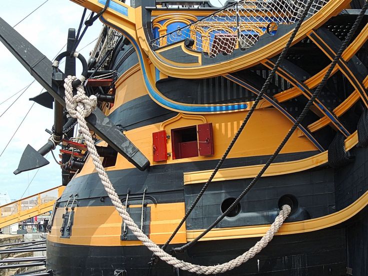
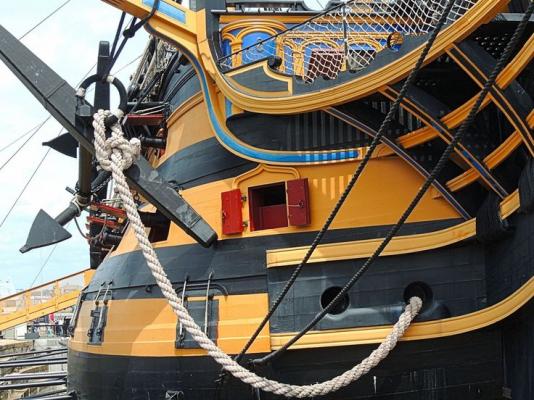
This is cable on HMS Victory. It is made from three strands of already made rope, so 9 strands, 3 X 3, to make one cable, and you can see the lines of the rope used to make up the cable. It is quite distinctive in appearance. 3 ropes made up left hand make into one cable made right hand. A 'cable' was 100 fathoms, 600 ft., and since about 1/4 of the length was lost in making up rope, upwards of 750 to 1000 ft. was needed to build a ropewalk. Additionally, I believe from my research that it would be wormed full length, a strand of small line being run in each of the cont lines, to help fill in the 'trough' in between the strands and keep the mud, stones, etc. from damaging the cable. The whole thing would be well tarred for waterproofing as well. A friend has described it as 'like a length of iron rebar' in stiffness. When USF Consitution was fitting out for the first time, some 300 to 400 people carried her cable from the ropewalk down to the harbor.
- 29 replies
-
- 1
-
-
- Rope making
- z twist
- (and 2 more)
-
I believe, without checking my sources, that there would be, in addition to the bolt, a block of wood also sliding in the slot. The traverse of the slide, by way of its wheels, would be enough for aiming, and, as you suggest, the carronade would be unstable and not function well if the carriage could pivot as you have shown on the slide. The elevation screw would remain in a position where it would function as well.
-
You're certainly approaching it from a novel angle! I have made spar stock by gluing up quarters, one 1/2" dia. spar made from four 1/4" square pieces. If you align any curves/warps so they counteract each other it should be a stable assembly.
-
no garboard strake
jbshan replied to kier's topic in Building, Framing, Planking and plating a ships hull and deck
And I forgot to mention that it wouldn't need to be all in one length. It could be in three or four lengths and that would help with the width problem. -
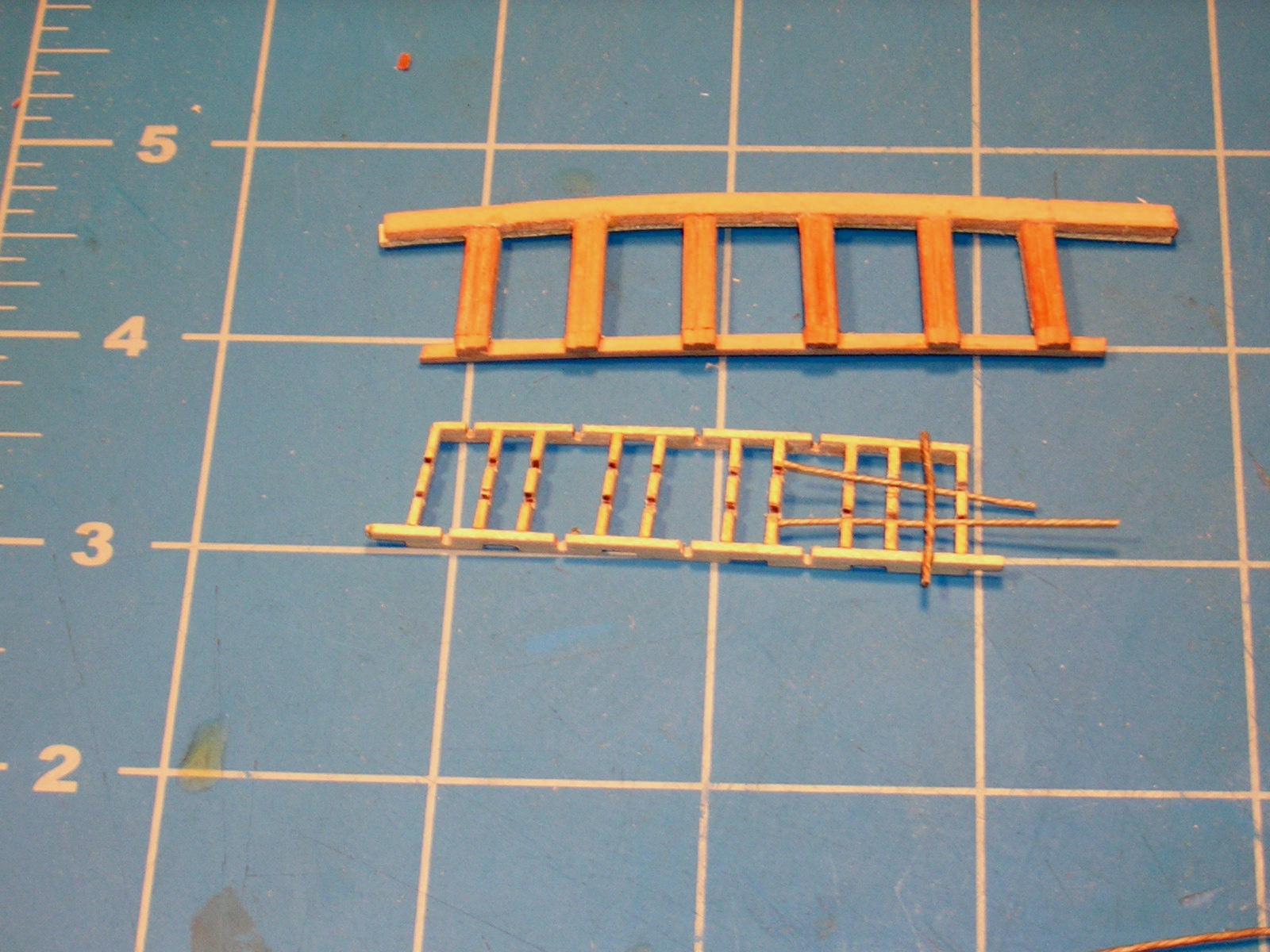
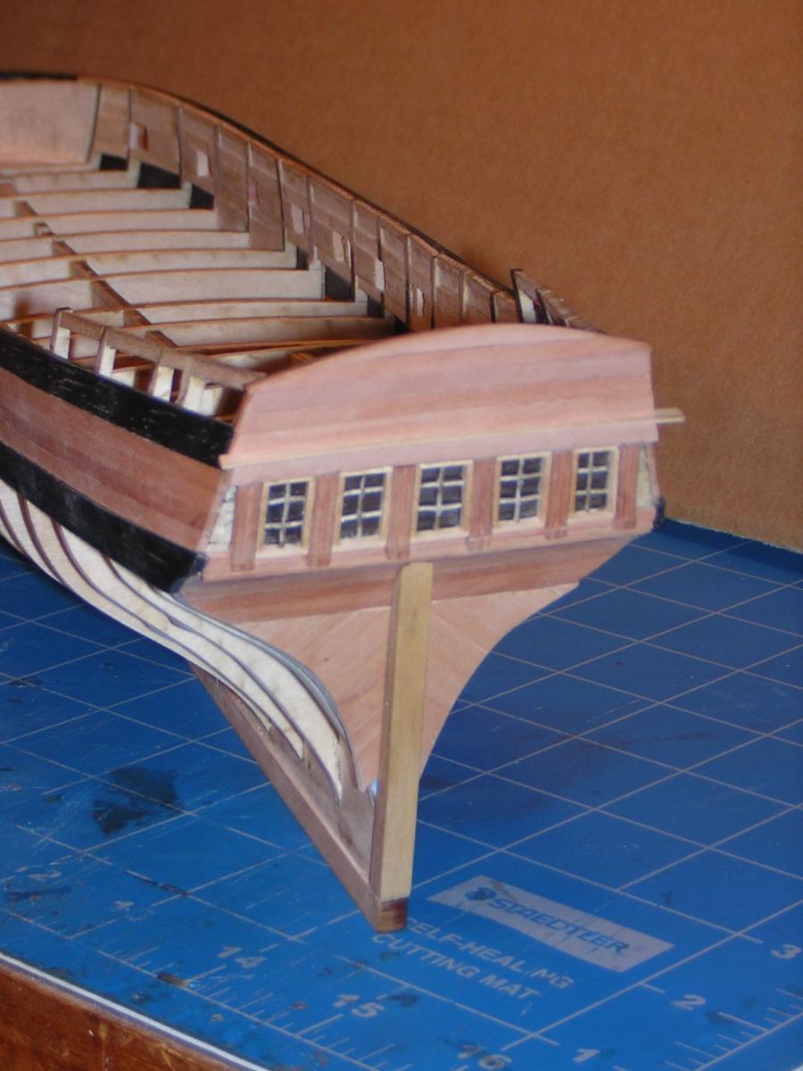
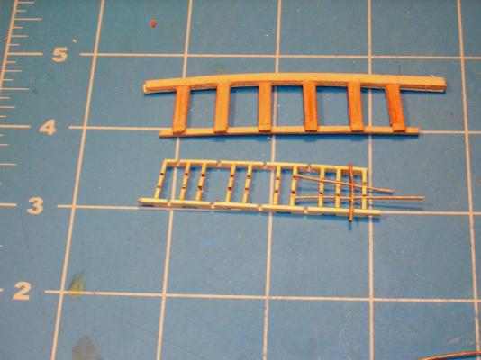
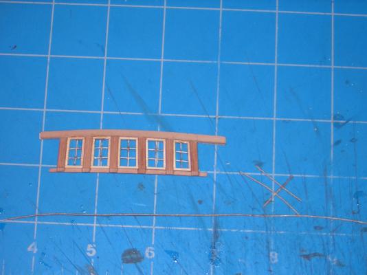
Here's what I have for the stern lights. The top assembly is the outer frame, what you see on the model. The lower assembly is the inner frame. This fits in from the back, so you only see the edges of it. The slots are to take the mullions and muntins for the individual panes of glass. I made these of heavy thread as I doubted my ability to work so small in wood, though the quarter lights have changed my mind on that. Once the cross pieces were in place, on top of those (behind both the frames and mullions) I glued small pieces of mica or isinglass, once used in wood stoves for little windows, and earlier used for lights on ships, fancy that. I used fly fishing head cement which is clear, almost liquid, does not have the white powder you get with CA, and merely adds to the character of the mica sheet. I also used it to glue in the thread, and to glue the joints in the thread. Since the backing for this whole area is almost touching, I painted the backing black, which allows the mica just enough reflection so it shows nicely, I think.

-
Two notes: HMS President of (you say) 1829 was supposedly an exact copy of the USS President they captured at the end of hostilities in 1815, which may be why the earlier ship had a name change in that year. The USN had HMS Macedonian which they paraded about as a trophy, and the 1829 President was used the same way, being assigned at one point to the North Atlantic (Halifax) station in a time of tension between the two countries. Being in the UK as you are, you might look into the Caldercraft line of models as they are more local to you. Local shops might carry them, and be able to give you specific help if you get stuck. I'm sure there is a range of difficulty levels in their kits, and they have an excellent reputation for quality and accuracy.
-
no garboard strake
jbshan replied to kier's topic in Building, Framing, Planking and plating a ships hull and deck
Kier, the garboard is the first plank next to the keel, so you WILL have one. Whether it can be cut from the stock provided is another matter. It might need to be cut from wider stock. -
Tapering masts, spars and yards
jbshan replied to bryanc's topic in Modeling tools and Workshop Equipment
The group isn't defunct. The Journal, now titled 'Warships to Workboats' is available at http://modelshipwrights.wikispaces.com/W2W_Archives though I don't think the very first one or two are there. The purpose of the Journal is to spread information. Please give the URL if you post anything, so more people can learn about the existence of this free, downloadable journal. Please also be aware that some of our authors make their living through their writing so don't publish anything from the Journal without permission as the authors own any copyright, not the Journal. At least two of our authors are members here also. -
HMS Victory colors
jbshan replied to rafterrat_2005's topic in Painting, finishing and weathering products and techniques
Model Expo has/had a set. If the set isn't available, the paint numbers may still be good. http://www.modelexpo-online.com/product.asp?ITEMNO=SM23MS I have seen the current yellow color compared to cheddar cheese, but as with cheeses, paint colors of that time might change according to what source was used for the pigment as there is variation in the minerals ground up to make the paint color. The official website calls it 'mustard'. Recent work suggests the yellow may have been paler than the current. http://www.theguardian.com/uk-news/2014/mar/17/conservationists-discovered-colours-admiral-nelson-flgaship -
Harland also wrote a small book on the subject- 'Capstans and Windlasses: An Illustrated History of Their Use at Sea', Pier Books/DuPont Communications, 2003 .
-
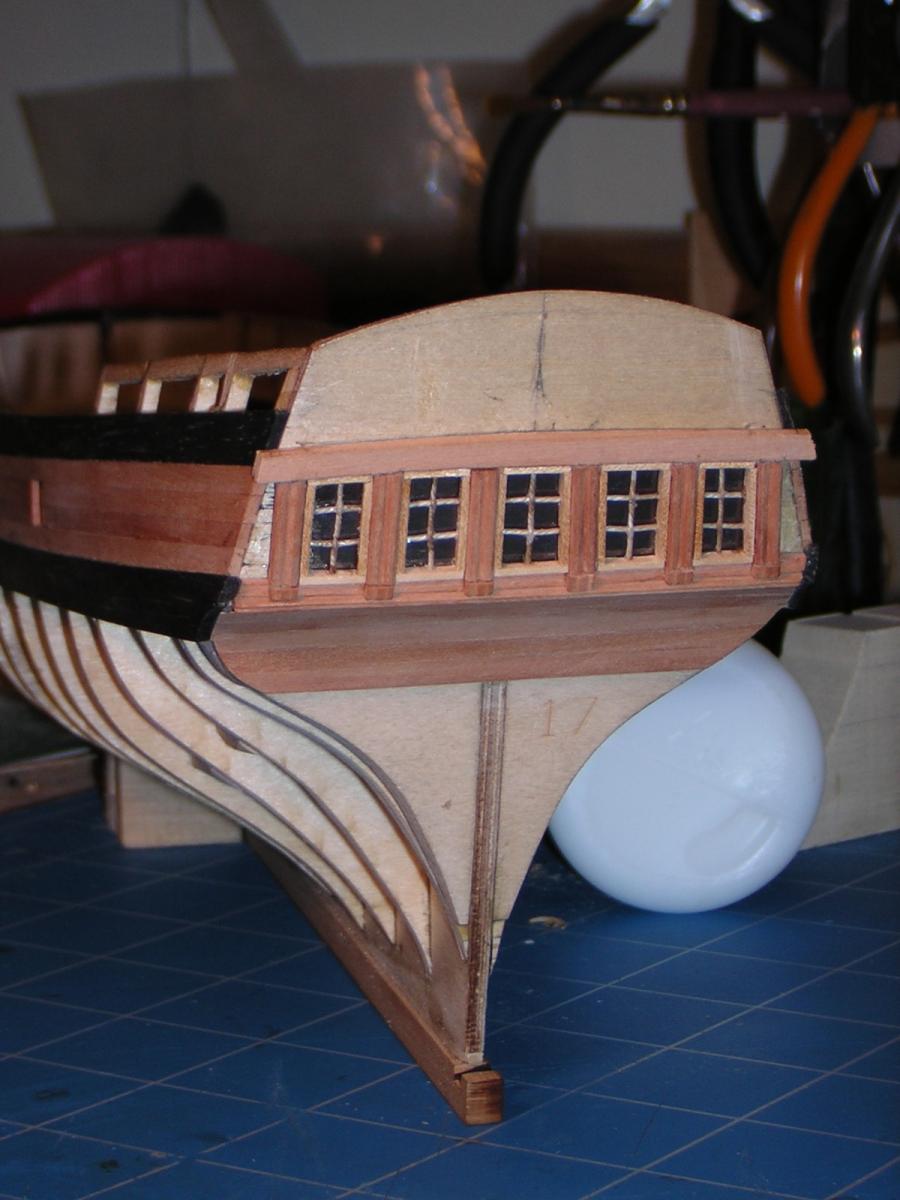
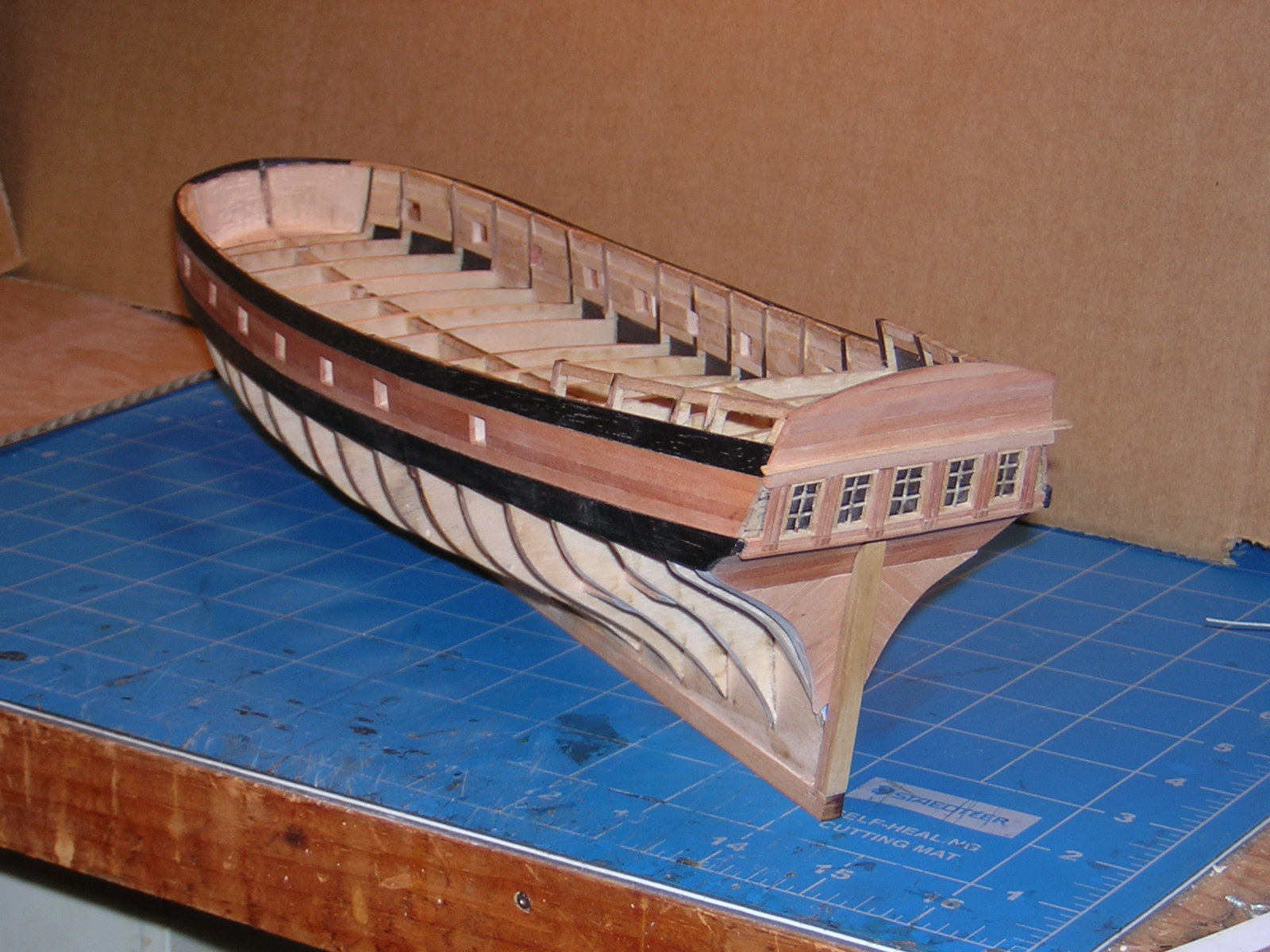
To blow these up, open in a new tab or window. I then see a magnifying glass with a '+' inside, or use the prompt under 'view' for zoom + or -. Here's about the next one in sequence. I took it to show the transom and stern lights but it will serve to show the planking process. First, having faired the blocking on the exterior, I put one strake of swiss pear along the bottom of the port openings. Using a batten to line this up makes this strake go in nicely. Next were the two strakes between the ports, again of swiss pear, then one more full strake. I held the strakes between the ports just to the edge of the openings in the blocking. The black strakes of plank are ebony. It is evil stuff. Next time I would use walnut or some other dark wood if I wanted the contrast in color. Here is a closer view of the square tuck stern. The planking is fairly straightforward here, though the photo is kind of blurry. The tafferail area is backed with some scrap 1/32" plywood and planked horizontally with swiss pear. The stern lights I will deal with in their own section. Below that is the counter, curved inward and set by a block that I think shows in one of the earlier pics. Below that is the tuck area that I planked diagonally, lower outboard rising to the center line. [edit: The stern post is applied on top of the plank.] I think you can see that I have left the top molding for the stern lights and the ends of the tuck long, later to be brought down flush, either to the side plank or to allow the bottom plank to run by and be in turn sanded back flush. There will be short horizontal pieces of plank outboard of the stern lights added before that area is brought back flush with the side.


-
Seeking information on determining load waterline
jbshan replied to trippwj's topic in Nautical/Naval History
They put into the specs where they *wanted* the ship to float, but if wishes were horses ... -
I used the stock keel and stem. Mine was one of the first sets sent out. I have another set one of the local club members decided he couldn't use because of health. I've used a little of the wood, but haven't touched the cut parts. I'll take a look later. LATER: 1/8 for the ply and 3/16 for the keel
-
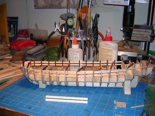
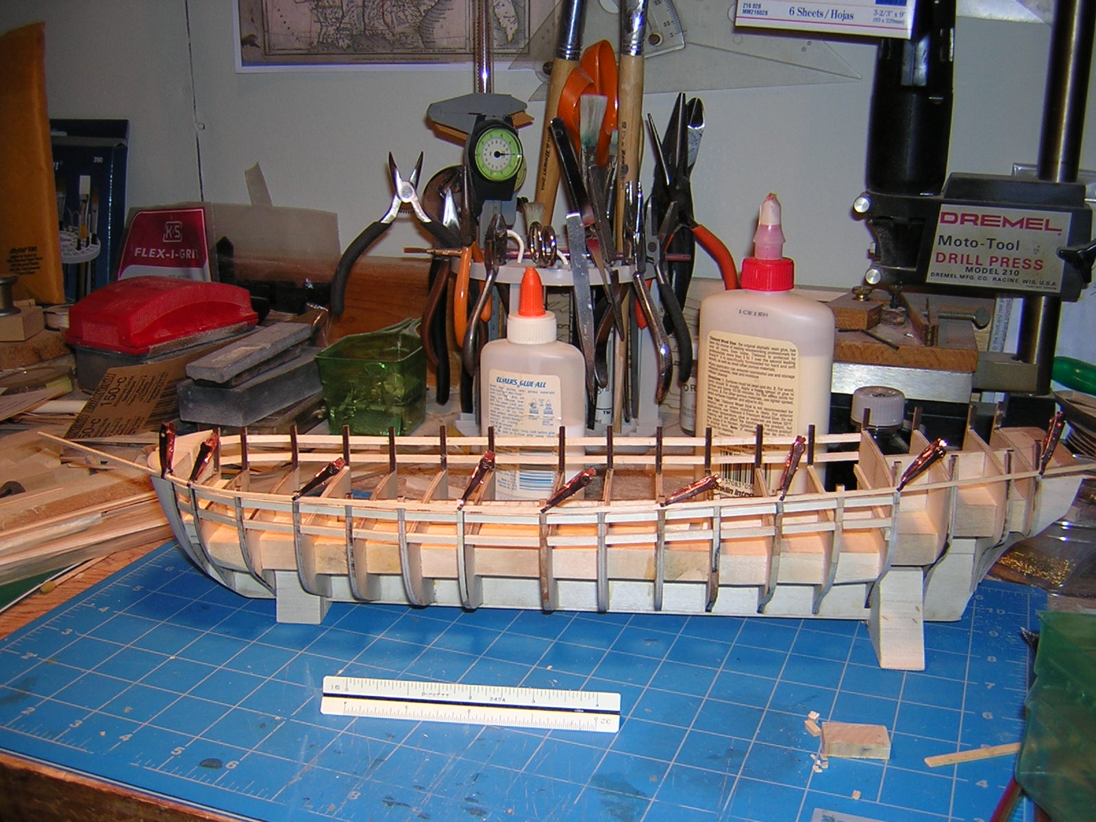
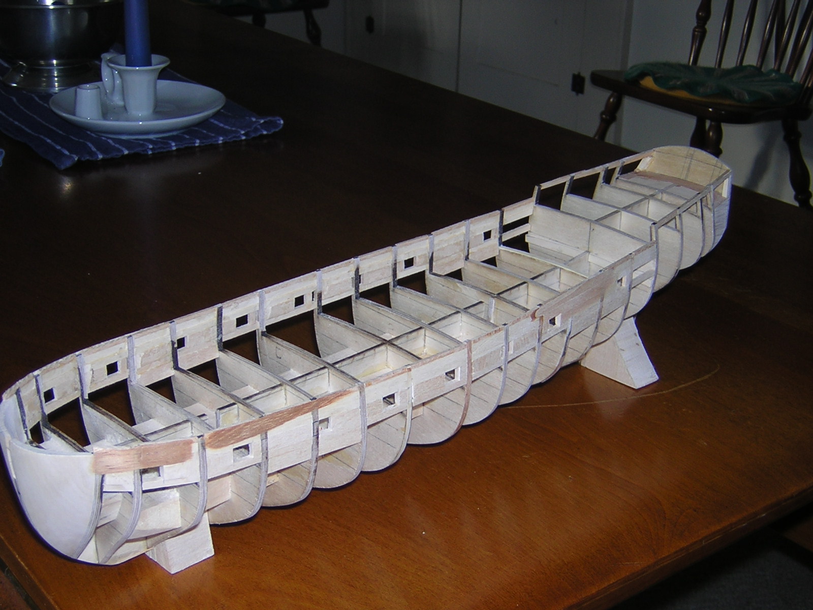
Here's about the earliest one, clamping a batten for the sheer. The top and bottom blocking for the ports is in. The kit is the standard 'egg crate' construction. It is a square tuck stern so pretty simple back there. I learned building Niagara by Model Shipways to block in the ports between the frames. It locates them securely and really stiffens things up. I ran battens for the top and bottom lines of the ports then measured for locations fore n' aft. One each side needed the frame to be cut right out, about midships. The third back needed the frame cut, but had blocking adjacent on the fore side to support the edge. The forward ports had to be at an angle because of the curve in toward the bows and that angle had to be allowed for. I make the blocking proud of the frames, then sand back to a smooth surface. The blocking makes putting in the port lining much easier later on. This vessel has the plank basically following the ports, but I would think this method would help with those where the plank does not line up, and easier than trying to measure each port out and cut already installed planking. I may remember more as we go but this is it for now on these pics.