jbshan
-
Posts
1,222 -
Joined
-
Last visited
Content Type
Profiles
Forums
Gallery
Events
Everything posted by jbshan
-

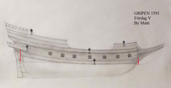
Gripen 1591 by NAZGÛL (Matti)
jbshan replied to NAZGÛL's topic in - Build logs for subjects built 1501 - 1750
You've designed a pretty ship, Matti. I'll be checking in from time to time to see how she develops. -
Specifications for Construction of U.S. Navy Ship Models
jbshan replied to Rob Wood's topic in Nautical/Naval History
It is allowed to use thinned white glue to secure knots and ends of line. Creeping slowly into the 20th century :-) -
If we learn from our mistakes, I must be pretty smart now.
jbshan replied to skipper1947's topic in Wood ship model kits
My old professor used to say 'never see it on a trotting horse', which I guess, just by speed, is a titch more fussy than your galloper. Yes, kit companies make mistakes. I wonder if they manufactured your kit so the supplied parts and plans conspired to give you problems, in other words the kit and plans didn't match. If the side scroll work is too short for the woodwork, or rather the wood is too long, when you put in the quarterdeck and stairs, there isn't room for the gun. That's one solution. Another solution is that the stairs are designed to be moved toward the centerline for action, and that makes room for the gun to function. It could be normally secured sideways to the bulwark and only brought out into battery at need. The crew could exercise at the adjacent gun while theirs was out of battery behind the stairs. I like to think of the process of building as also including 'covering up my tracks', by which I mean covering traces of what I needed to do to hide a mistake. I know it's there, but you're going to need magnifying lenses or X-Rays to find it. We should learn from our mistakes, but we don't have to take out a billboard about it. -
Specifications for Construction of U.S. Navy Ship Models
jbshan replied to Rob Wood's topic in Nautical/Naval History
A fellow member of my local club also belongs to a few clubs around the country. He *has* seen rigging come apart at the CA/non CA line. Maybe they're better formulated now, but I, and Mr. Wegner, will probably stay away from them. Likewise with lead-bearing cast fittings. A lot of his restrictions are based on longevity concerns. It takes 100 years to test whether a material will last 100 years, so be patient, or be willing to take the chance. Your heirs can always have a nice Viking funeral for your work if it falls apart. Another part of Mr. Wegner's requirements is for detail. He sets a minimum size for representation of items. If you take a careful, objective look at old models, such as the basket case in Rob Woods photo, there are a lot of things we would include today which are not on that model. Wegner's requirements are for models of Naval ships in a Navy museum which are usually highly documented and are basically builder's models. It is important for that purpose that the model serve as a record of the actual ship, down to a certain level of detail. In this particular instance, while we can take guidance for our own work, it is his museum, and he gets to define what is suitable for inclusion (and payment) and what is not.- 16 replies
-
- 1
-

-
- Specifications
- US Navy ship models
- (and 1 more)
-
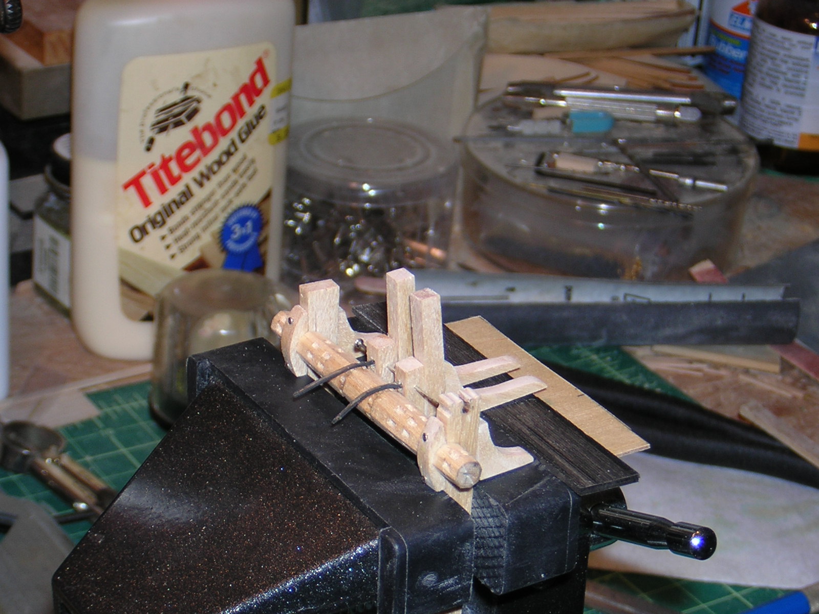
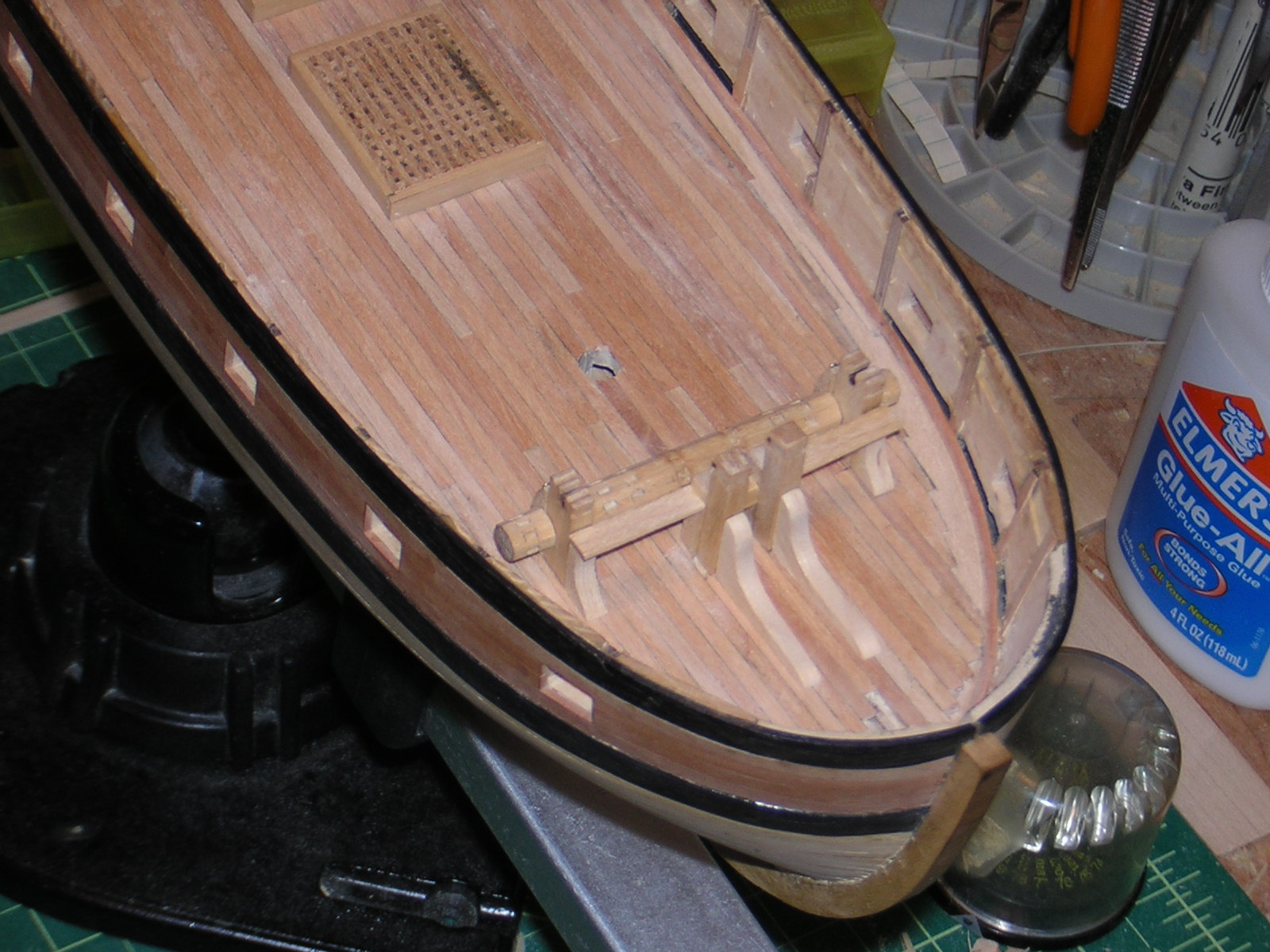
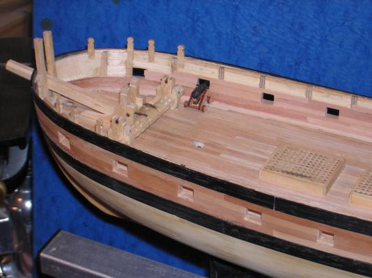
I'm getting a bit out of sequence now, but this is another item of deck machinery that I can cover fairly concisely. Windlass: The basic design I got out of John Harland's small book, 'Capstans and Windlasses', I think, at least there is a similar one in there. The barrel is made from four pieces of maple glued up to get the required diameter. This helps keep it straight and stronger, also less likely to split. It's all octagonal, with a straight section in the middle and tapering toward the ends. Notches for the pawls are cut with a tiny chisel (homemade) at the end of the straight section, and sockets for pulling bars from there out. Where the barrel passes the riding bitts is a narrow section acting as bearings in sockets cut in the bitts and the clamp. In this front view you can see the standards clearly, both those on the riding bitts and the larger ones on the bitts that hold the heel of the bowsprit. Between the bowsprit bitts and the barrel of the windlass are two more posts, these have the pawls in their after face. With the pawls working, you would pull down and aft on a bar, pulling in the cable. Loosen up tension on the bar and the pawl slips down keeping the barrel from freewheeling backwards. There is one more crossbar, it will have belaying points for the headsail halyards, etc. Back to an after view, you can see the pawls in their final form and the thumb cleats atop the riding bitts. The cable would be permanently wound around here, lashed up off the barrel in a large circle when not riding to anchor. Stoppers would do much of the work of holding the cable when anchored. The gun is there to check clearances. The pins used for dry fitting will be smaller headed and blackened in final assembly. You can see a mockup bowsprit stub in place. This will have small foredeck platforms P&S to access swivels located over the rail here. You can also see the timberheads and how they insert into the structure. There will be more on those perhaps later.


-
Matti, I did a little more looking around as well. The elaborate shapes you drew seem to be on larger ships, and, it must be said, on ships farther in the background of the pictures. Talos, I don't think it is perspective, I think the double curves are accurate. I think a stern gallery that followed the roundup of the deck would appear in the aft view as two arcs, one top, one bottom. Since the stern of the ship rakes aft, and is not rounded aft, if the gallery followed that rake, there would be no reason for a double curve to appear 'by accident'.
-
I think I would just go with straight lines on the galleries, Matti. The side galleries will be rising up with the sheer as they come aft, and the part across the stern could have the same roundup as the deck, parallel with the bottom as you have it drawn. That should be enough.
-
There isn't one complete source from that time, of course. Lavery says he started with 'the Admiralty Library Manuscript' which he describes as 'an anonymous treatise on shipbuilding, believed to have been written around 1625'. That document gives a port size of 2 1/2 feet square, which he then adjusts to fit the frame spacing he has previously worked out. Everything is interrelated; change one thing and you have to adjust something else. Fun, isn't it?
-
I've been doing some more looking. You probably have guns in the small range of size. Ports get smaller with smaller guns, but there is a limit. Your ports probably want to be in the range of 71 to 76 cm on each side, or 2ft. 3 inches to 2 ft. 6 inches square. This is from Susan Constant, Brian Lavery, from the AOS series by Conway. This ship dates from 1603-05 and the book is a reconstruction based on best evidence to assist the Jamestown VA folks to replace their replica ship.
-
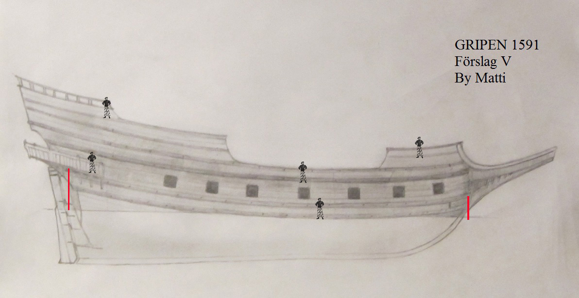
32 meters is what Matti mentioned. I applied that dimension to about the perpendiculars (rabbet of the gundeck) just to get a rough approximation. Putting the men in now gives a sense perhaps if it is too long or not.
-
Sharp and small. I used a home made chisel from an exacto blade, so you don't need to spend hundreds of dollars, though mine is a little flimsy. Good thing, though, perhaps, as it made me go slowly. The books mentioned will also teach you what your result should be like, in shape and curve, etc. That's important, too.
-
What I'm thinking of as scale to determine heights of deck etc. would be merely a human figure you could put in different positions to compare to your design. I find it a very useful tool. You note Cathead's photo from NC has only one wale. Most we have been looking at have two rails in the lower wale. I read, about two days apart, that 'no English ship at this time (happened to be 1650) had more than two rails in the lower rails, and a sketch from the time that had three. It seems that things aren't actually carved in stone, that there are always exceptions to any rule. Just to show what I mean by scale, I took your latest drawing and added some figures. If it is 32 meters between my two red uprights, then the men are about 2 meters tall.
-
Matti. Think about making the spacing between the two lower wales wider. That will let you raise your ports a little. I like the new look.
-
Jan wrote: "Mind, the pics of Dutchships shown are all from the post-Wasa period. It's not at allo clear whehter or not they provide you with info on how a pre-1600 ship would have looked like." I've been looking around and I think Jan is getting close. I'm still going for option 'A', but I like the stern gallery as in 'B'. Earlier, and you're going for more than 50 years before the van de Velds, and in smaller vessels, I'm seeing gun ports higher up, into the 2nd or chain wale. This puts the guns, because of the size of the ship, onto the weather deck. Do please work out where your decks/platforms will be located because deciding the combination of deck and port location will probably help work out the rest. I don't think only one deck exposed to the weather is correct. Everything has to go down a hatch anyway, and it wouldn't hurt if the cargo had someplace besides on top of the ballast to sit. I think there would be a platform or two at least.
-
Even the pinnace, Matti, as, if you look particularly at the van de Veld sketch in tallship's posting, the water comes quite farther up than the line or division drawn on the pinnace. The water comes about to the lower rail of the lower wale on all the other pictures. If the deck is also about there, the guns work out about right with regard to headroom and clearance for the barrels of the guns. Except for Kalmar Nyckel, for which I do not know the sources they used. Perhaps smaller or earlier ships were set up differently. Have you looked at pictures of the Spanish Armada and the English 'race-built' galleons? These English ships I think might be the forerunners of the type of vessel you're looking for, similar in look to the votive model somebody put up earlier.
-
The lower wale would be at about the level of the lower deck inside as it and the deck clamp would be fastened through each other. All four of the latest pics have a row of guns in the section just above the lower wale's upper rail. The lower wale is also at about water level.
-
Try wrapping a strip in a damp paper towel and putting it in the microwave.
-
I think picture 'A' is probably more likely. Check out port locations on Mayflower II. The guns are not on the open weather deck. The decks would probably not be continuous at this time. There might well be a step down aft, especially into any cabin area, and there might be a leveling off aft on a gun-bearing deck so any guns could be more easily moved into aft ports.
-
We have not considered Portugese, Spanish, any of several Italian cities, etc., etc. for their tonnage ratings. They probably are all different and all relate to cargo not displacement of water.
-
In re tonnage: Before the middle of the 1800s a ship's tonnage was either a calculated amount or an actual measurement. In both cases it was a measurement or approximation of the cargo a hull could carry, it was not displacement. The number of 'tuns' of wine a ship could carry, with a new ship perhaps actual stowing of barrels, would determine her tax liability, and the size of a warship followed the same principles. The calculations for British ships resulted in a number ending in /94 of a tun, i.e. 397 52/94 tuns. American usage resulted in /95 of a tun. Since the 'tonnage' was based on breadth, length of assorted parts, etc., two ships could have identical tonnages and be quite different if they had merely the same breadth and length. No accommodation was made for the fullness or sharpness of the hull. Don't be too quick to eliminate that lower aft port. It might be a ballast port; the lower deck or platform would be near there, it is near the waterline for shoveling ballast out of a boat and it can be caulked and nailed shut for the voyage.
-
Cross-Jack Yard on a cutter (Sherbourne 1763)
jbshan replied to tkay11's topic in Masting, rigging and sails
I seem to recall a discussion on another group years ago about this. I think the term comes over from Dutch, with the usual 'Englishification'. -
Cross-Jack Yard on a cutter (Sherbourne 1763)
jbshan replied to tkay11's topic in Masting, rigging and sails
As suggested, the yard used to spread the foot of the topsail could be called a cro'jack, even though it isn't on a mizzen mast. Depending on the particular vessel, there might be a 'fair weather sail' spread below the topsail on a cutter which would have its own pair of yards, or it might be bent to the 'cro'jack' and have another yard to spread its foot. If it had its own yard for the head of the sail, that yard might be hoisted on a 'horse' which was a rope running from the cap to the deck. This keeps this portion of the square sail rigging from interfering with the gaff sail. Biddlecombe has a listing for a 'jack stay' and I wonder if that is this 'horse'. I welcome clarification on the terms used for these items. -
Cross-Jack Yard on a cutter (Sherbourne 1763)
jbshan replied to tkay11's topic in Masting, rigging and sails
Biddlecombe was writing in the mid-1800s, but his work is based mostly Steel who was writing in the 1790-1800s. I looked at your log, and Caldercraft should have given you dimensions for the spars. -
Thinking Things Through - French Frigates
jbshan replied to mtaylor's topic in Nautical/Naval History
Did you get to the bottom of your measurement discussion? The translator of the Boudriot '74 Gun Ship', in a marginal note, explains some of that, and Boudriot used pre-revolution measurements, which is also explained. Makes sense, deuxieme, troisieme, though I've only seen it as eme. Obviously some holes in my education. There was an American source for Ancre publications, but he dropped that line. You'll have to go used or try Ancre from France. -
I haven't been able to find any drawing showing other than just the big pivot under the barrel, no block to keep it aligned in the slot. Since this has a large washer or retaining ring, and the slide has a slot for the ring, I can only assume this would be enough to keep the barrel from rising. They made a replica of one of Vasa's long guns and fired it, first with no recoil lines, breeching or tackle, and then hooked it up to the normal lines. Without breeching or tackle it was a wild ride! With them the gun was very tame and mannerly. Remember, the breeching only serves as an ultimate stop, most of the recoil is taken up by pulling the tackle through the blocks. I wonder if the carronade likewise would be 'tamed' and it could recoil with only slight ('slight' being a relative term here) pull up on the muzzle, just enough to keep it in contact with the slide at the rear.