trippwj
-
Posts
3,156 -
Joined
-
Last visited
Content Type
Profiles
Forums
Gallery
Events
Everything posted by trippwj
-
 Jersey City Frankie has made a couple of good points, Dashi, which you seem to dismiss out of hand. Reliance on a marking that appears on but a single plan over others is not the historians route. By any chance does this same plan show the mizzen step? Accuracy assumed for one aspect should agree with the others. One must recall that Cook was extremely familiar with colliers. As a general vessel type, were the tillers longer than expected? While modified by a Naval yard, the ship was originally and would remain fundamentally a collier.
 -
High there, John! Actually have a domain on Bluehost. Would appreciate any advice as I move forward! http://nauticalresources.info/
-
I probably could. Just need to figure out how to build and support a database integrated into the website. Very early draft is up - note that it is still a very early work in progress. Working to learn Wordpress as well as figure out a database method. (Yep, never done anything with a web page before). http://nauticalresources.info/
-
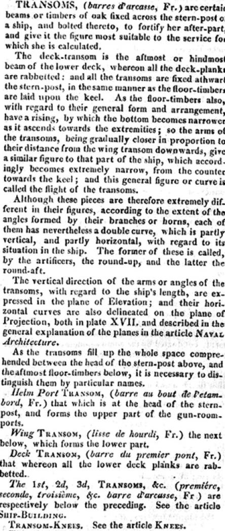
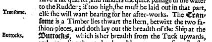
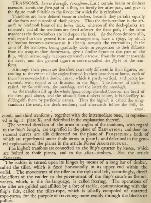
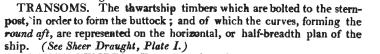
Actually, i think there is some logic to the addition of a support given the odd geometry and the length of the tiller. I was just supporting an earlier post concerning the use of the word transom. None of the period treatisers on shipbuilding chose to use that word to describe anything other than the stern timbers.
-
Here are some expanded definitions from the 1815 (Burney) edition. ALL identified transoms are the transverse timbers across the sternpost. Falconer, William. 1815. Falconer’s New Universal Dictionary of the Marine: 1815 Edition. Naval Institute Press. http://www.ageofnelson.org/Document11.html.

-
Each definition is for the noun transom - as used during the 17th and 18th centuries, no further description was needed, other than perhaps which of the transoms at the stern post (upper, middle etc), There were no other definitions for transom in these reference works.
-
For what it's worth, here are a few contemporary definitions of transom: Smith, Captain John. 1691. The Seamans Grammar and Dictionary, Explaining All the difficult Terms Navigation: And the Practical Navigator and Gunner: In Two Parts. http://www.shipbrook.net/jeff/seamansgrammar/. Falconer, William. 1769. An Universal Dictionary of the Marine: Or, A Copious Explanation of the Technical Terms and Phrases Employed in the Construction, Equipment, Furniture, Machinery, Movements, and Military Operations of a Ship, Illustrated with Variety of Original Designs of Shipping, in Different Situations; Together with Separate Views of Their Masts, Sails, Yards, and Rigging. To Which Is Annexed, a Translation of the French Sea-Terms and Phrases, Collected from the Works of Mess. Du Hamel, Aubin, Saverien, &c. London, Printed for T. Cadell (successor to Mr. Millar) in the Strand. http://archive.org/details/universaldiction00will. Steel, David. 1805. The Shipwright’s Vade-Mecum. http://archive.org/details/shipwrightsvade00steegoog
-
Count me in, Sjors! I promise not to drop any pop corn or spill my beverage!
-
Mast Lengths and their above deck heights for HMB Endeavour
trippwj replied to dashi's topic in Masting, rigging and sails
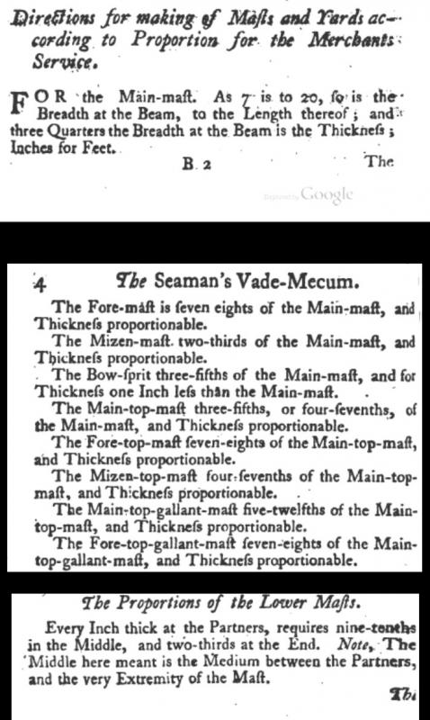
One last item to consider: The following excerpts are from Mountaine, William. 1761. The Seaman’s Vade-Mecum and Defensive War by Sea. http://books.google.com/books?id=a8IzAQAAMAAJ.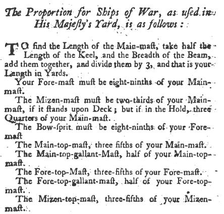
- 63 replies
-
- 2
-

-
- HMB Endeavour mast lengths
- above deck mast heights
- (and 3 more)
-
Mast Lengths and their above deck heights for HMB Endeavour
trippwj replied to dashi's topic in Masting, rigging and sails
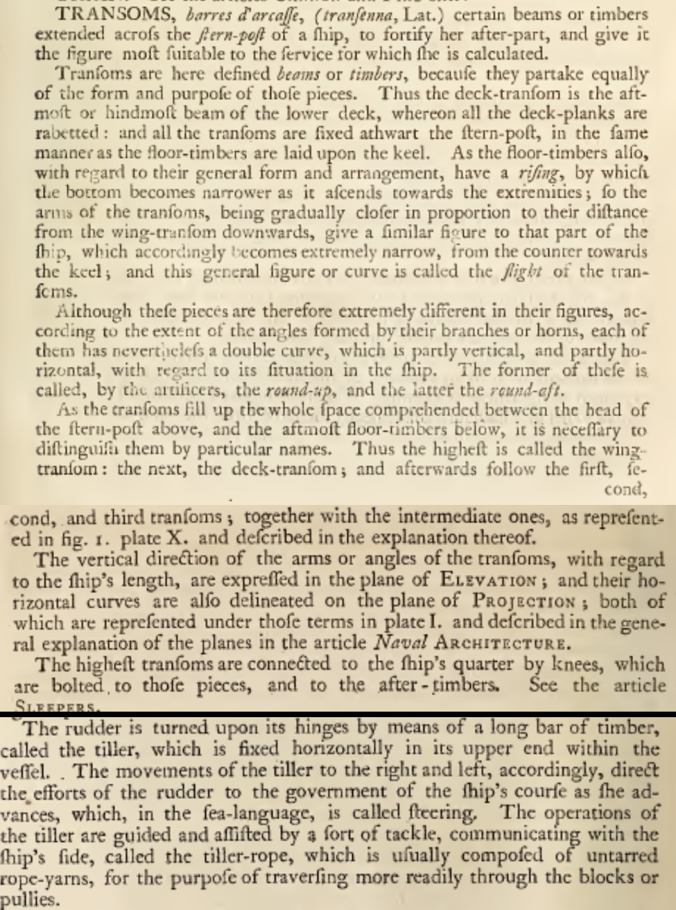
ooops....got disoriented looking through the plans! You are correct, that is the great cabin not the lower deck. Disregard that one! Boy, do I feel silly! Can I offer ZAZ6594 as compensation??? EDIT: Links I had added are provided in the post above.

- 63 replies
-
- 1
-
-
- HMB Endeavour mast lengths
- above deck mast heights
- (and 3 more)
-
French rigging practice in the days of spritsail topsail
trippwj replied to cerberusjf's topic in Masting, rigging and sails
The articles mentioned are available on the CD that you can purchase at the NRG website. -
Mast Lengths and their above deck heights for HMB Endeavour
trippwj replied to dashi's topic in Masting, rigging and sails
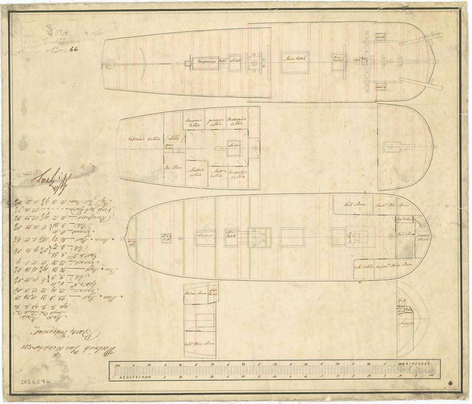
One of the challenges, or perhaps benefits, of the NMM is the abundance of draughts for some vessels. Here, for your consideration, I offer the following: Object ID ZAZ6591 Description Scale: 1:48. Plan showing the after fall (platform) with the great cabin for Endeavour (1768), a purchased collier, prior to final fitting as a ship-rigged Bark for exploration. Date made April 1768 Note the absence of deck beams below the mast - the red lines indicate the additions made to the vessel in the area to support this added level. The beams are evident. If the mast were to step here; it is quite likely that at least one beam would be very close to the step. The absence (and the circle representation) are indicative of the mast passing through the deck, not stepping upon it. When we look at the mast heights above deck, all the contemporary representations of the vessel indicate the mizzen was significantly shorter than the main or fore masts. Finally, I would not assume that William Gray [Master Shipwright, Woolwich Dockyard, 1767-1773] would sign off on the dimensions if he had not reviewed them and found them accurate. If we are willing to accept the other drawings as accurate and indicative of the as-refitted condition, why would you doubt these values? Remember, Steel was offering guidelines, not rules or requirements. The captain of a ship still had a great deal of freedom in the masting and rigging. Running the numbers based on the Woolwich values, I find the following: Fore Mast - closest match is Merchant vessel of 400 tons Lower Mast Length 65 feet 4 inches with height above deck of 47 feet 4 inches Steel's Tables for a Naval sloop of 300 tons - 56 feet 0 inches Naval 20 gun of 429 tons 64 feet 0 inches Merchant of 350-360 tons - 63 feet 0 inches Merchant of 400 tons 65 feet 0 inches Main Mast closest match is a Merchant vessel of 400 tons Lower Mast length 69 feet 4 inches with height above deck of 48 feet 10 inches Steel's Tables for a Naval sloop of 300 tons - 63 feet 0 inches Naval 20 gun of 429 tons 72 feet 0 inches Merchant of 350-360 tons - 65 feet 0 inches Merchant of 400 tons 70 feet 0 inches Mizzen Mast closest match is a Naval sloop of 300 tons, though a poor match. Lower mast length 50 feet 5 inches with height above deck (stepped to keelson) of 28 feet 5 inches of 20 feet shorter than the Main mast above deck. Steel's Tables for a Naval sloop of 300 tons - 48 feet 0 inches Naval 20 gun of 429 tons 61 feet 0 inches Merchant of 350-360 tons - 58 feet 0 inches Merchant of 400 tons 62 feet 0 inches The wide disparity in these between the tables from Steel and the reported for Endeavour are quite eye opening.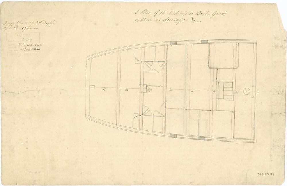
- 63 replies
-
- 2
-
-
- HMB Endeavour mast lengths
- above deck mast heights
- (and 3 more)
-
Mast Lengths and their above deck heights for HMB Endeavour
trippwj replied to dashi's topic in Masting, rigging and sails
Not the mast step but rather the support structure beneath were it stepped to the deck not the keelson. That's alot of weight added to an unstrengthened base. You would expect to see added structure beneath the deck to mitigate collapse.- 63 replies
-
- 3
-
-
- HMB Endeavour mast lengths
- above deck mast heights
- (and 3 more)
-
Mast Lengths and their above deck heights for HMB Endeavour
trippwj replied to dashi's topic in Masting, rigging and sails
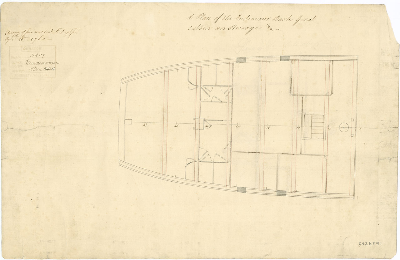
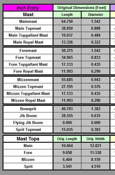
Interesting conundrum on the foremast. Here is the table of masts and yards from ZAZ6594, described as Scale: 96. Plan showing the quarterdeck, upper deck, forecastle, fore & aft falls (a type of platforms), lower deck, and fore & aft platforms for Endeavour (1768), after being re-fitted at Woolwich Dockyard. Signed by William Gray [Master Shipwright, Woolwich Dockyard, 1767-1773]. This same plan sheet shows the deck arrangements (both images may be found at ‘National Maritime Museum, Greenwich, London’, http://collections.rmg.co.uk/collections/objects/86385.html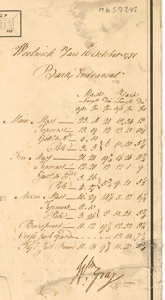
- 63 replies
-
- 2
-
-
- HMB Endeavour mast lengths
- above deck mast heights
- (and 3 more)
-
French rigging practice in the days of spritsail topsail
trippwj replied to cerberusjf's topic in Masting, rigging and sails
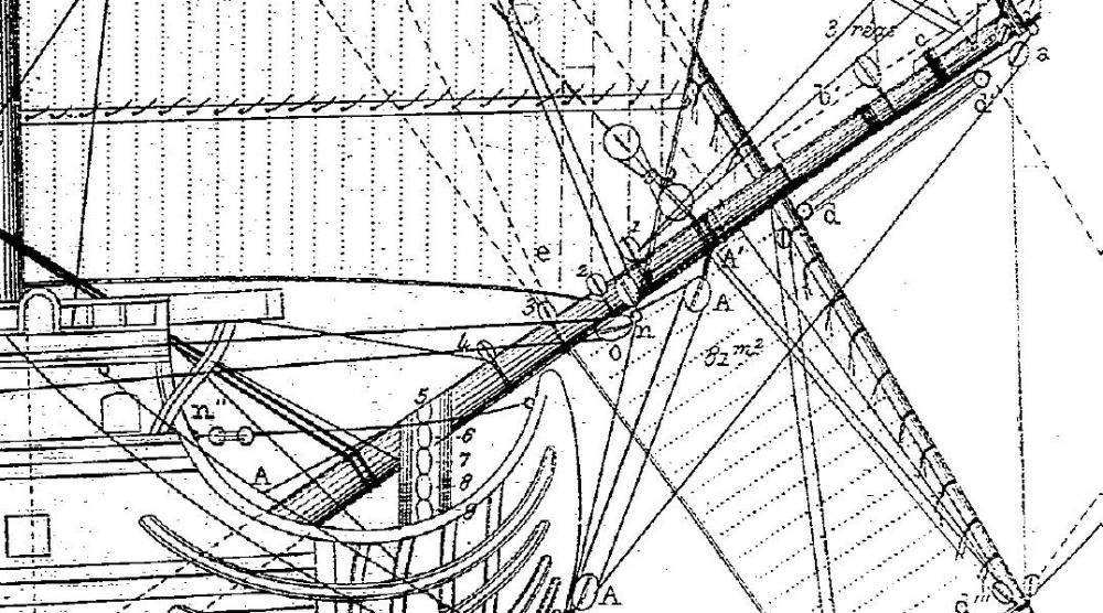
Good choice of reference for the rigging. I am not particularly familiar with French practice, but offer you the following. Pâris, Edmond (1806-1893). 1882. Collection de plans ou Dessins de navires et de bateaux anciens et modernes, existants ou disparus : avec les éléments numériques nécessaires à leur construction / par le vice-amiral Paris,... http://gallica.bnf.fr/ark:/12148/bpt6k5699565s. Here are a couple of excerpts from his drawings Royal Louis???)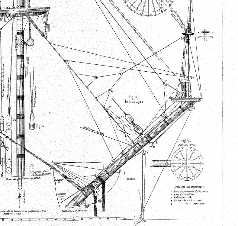
-
Robin - Here is the link to the Layman pamphlet Layman, William. 1813. Precursor to an Exposé on Forest Trees and Timber ... as Connected with the Maritime Strength ... of the United Kingdom. https://books.google.com/books?id=KNxbAAAAQAAJ. The Naval Chronicle for 1818 has an interesting little addenda to the Biographical memoir for Captain Layman as well (which mentions the pamphlet). See Gold, Joyce, ed. 1818. “Addenda to the Biographical Memoir of Captain William Layman of the Royal Navy.” The Naval Chronicle, Containing a General and Biographical History of the Royal Navy of the United Kingdom, with a Variety of Original Papers on Nautical Subjects 39 (January to June, 1818): 177–85. https://books.google.com/books?id=4AFdAAAAcAAJ.
-
In what context, Victor? Founded in 1860, they are still a very active professional society (website: http://www.rina.org.uk/). Many of the older volumes of Transactions can be found on the internet (see detailed index here Royal Institution of Naval Architects. 1905. Index to Transactions of the Royal Institution of Naval Architects Vol 1 - 54. https://books.google.com/books?id=8cU6AAAAMAAJ.)
-
Mast Lengths and their above deck heights for HMB Endeavour
trippwj replied to dashi's topic in Masting, rigging and sails
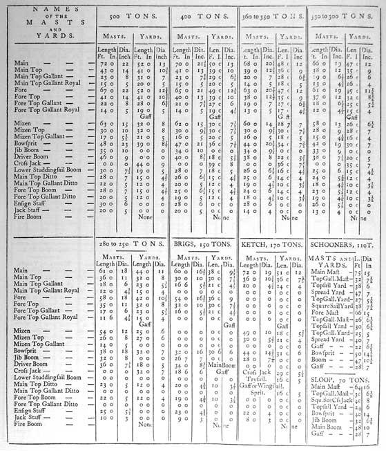
Here is another point to ponder - the following are from The Elements and Practice of Rigging And Seamanship, 1794, by David Steel (online at http://www.hnsa.org/resources/manuals-documents/age-of-sail/the-elements-and-practice-of-rigging-and-seamanship/ ) First, a table of masts for Naval vessels of similar tunnage Now a table for merchant vessels of like tunnage.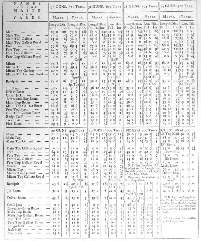
- 63 replies
-
- 3
-
-
- HMB Endeavour mast lengths
- above deck mast heights
- (and 3 more)
-
Mast Lengths and their above deck heights for HMB Endeavour
trippwj replied to dashi's topic in Masting, rigging and sails
The interesting thing about Steel is that he was neither a mariner nor a ship builder, but rather a lawyer (who once worked in the Admiralty and was fairly well connected) and a book publisher! It has been a topic of speculation over many years as to who actually wrote some of the materials Steel published. It was obvious where his Navy Lists came from, but the information on rigging and seamanship, not to mention his Naval Architecture, have been confounding historians for many a year.- 63 replies
-
- 3
-
-
- HMB Endeavour mast lengths
- above deck mast heights
- (and 3 more)
-
Mast Lengths and their above deck heights for HMB Endeavour
trippwj replied to dashi's topic in Masting, rigging and sails
Here's the output if you use the 1745 Establishment (spreadsheet courtesy of Danny Vadas, posted here http://modelshipworldforum.com/ship-model-masts-and-yards.php)based on a 20 gun 6th rate. If I change to a 30 gun we get the following.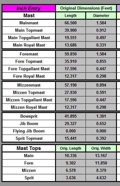
- 63 replies
-
- 2
-
-
- HMB Endeavour mast lengths
- above deck mast heights
- (and 3 more)
-
Mast Lengths and their above deck heights for HMB Endeavour
trippwj replied to dashi's topic in Masting, rigging and sails
I think Robin's point is that it would be a significant rebuild to the vessel to reinforce the deck to support the mizzen rather than stepping it to the keelson. I would use the results from Steel with a measure of caution - while it is a good starting point, it was not prescriptive (that is, did not describe how it must be done). You may want to take a look at Lees, James. 1984. The Masting and Rigging of English Ships of War, 1625-1860. He offers a variety of mesures for different periods, including a table from the 1754 Establishment for various rates. An additional check may be made of the early Universal Dictionary by Falconer.- 63 replies
-
- 3
-
-
- HMB Endeavour mast lengths
- above deck mast heights
- (and 3 more)
-
Greetings all. I have been gathering links to a wide variety of resources (old and new) available on the internet for use in model building. These range from scanned treatises from the 16th century (the oldest I currently have is from 1578) to available academic research (including theses and dissertations). Topics range from ship specific (such as the US Frigate Constellation) to highly generic (such as period treatises on rigging). I am contemplating posting these links to a website that I can update periodically, rather than continuing to update my posts here on MSW. Where i could use your help is, first, in getting a feel for whether you would use such a site, and second in deciding the best way to organize the website - I will not be uploading the actual documents, but rather a brief description with a link to the URL to access the document. Would it be more useful to be organized by subject (such as Dutch Shipbuilding; Masts and Rigging; Naval Architecture; Early American Frigate documents) or in some other manner? How would you want to be able to find the desired information on such a site? CAVEAT - I know NOTHING about web design, and am going to be learning as I go, so keep any advice on the structure and so on for a neophyte with little or no knowledge! Many thanks!
-
Brig USS Enterprise 1799 info gathering
trippwj replied to CharlieZardoz's topic in Nautical/Naval History
The copy at Mystic is probably one of those printed in 1973. Since Mystic does not own the copyright, only a copy of the plan, they can not offer reproductions - even for personal use. Unless he transferred it, Burrows owns the copyright. Wonder if anyone is familiar with him? -
Brig USS Enterprise 1799 info gathering
trippwj replied to CharlieZardoz's topic in Nautical/Naval History
I believe that you can order a copy of the 1973 plans by Burows. They list the following: ENTERPRISE: Lines; Profile SHIPS PLANS Blueline print Burrows, John Shober Blueline print SP.1973.4.14.21.1 http://mobius.mysticseaport.org/detail.php?t=objects&type=all&f=&s=SP.1973.4.14.21&record=1 ENTERPRISE: Schooner of war SHIPS PLANS Plans set Spencer, Henry; Burrows, John Shober 1973 1 sheet of plans for 83.5 ft. schooner of war, ENTERPRISE (built 1799), built by Henry Spencer. Date on plan is 1973. SP.1973.4.14.21 http://mobius.mysticseaport.org/detail.php?t=objects&type=all&f=&s=SP.1973.4.14.21&record=0 These remaining ones may be of the J class yacht Enterprise but not sure. SP.1983.12.43.83.1 ENTERPRISE: Lines Burgess, W. Starling View SP.1992.62.90.43.43 ENTERPRISE: Sail View SP.1995.1.1.908.1 ENTERPRISE: Sail; ENTERPRISE: Profile Stephens, W. P. View SP.1995.1.1.908.2 ENTERPRISE: Profile Stephens, W. P. View SP.1995.1.1.908.3 ENTERPRISE: Lines; ENTERPRISE: Arrangement; ENTERPRISE: Profile Stephens, W. P. View -
Metric vs English
trippwj replied to jdiven's topic in Building, Framing, Planking and plating a ships hull and deck
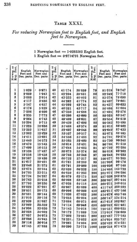
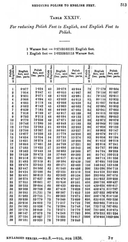
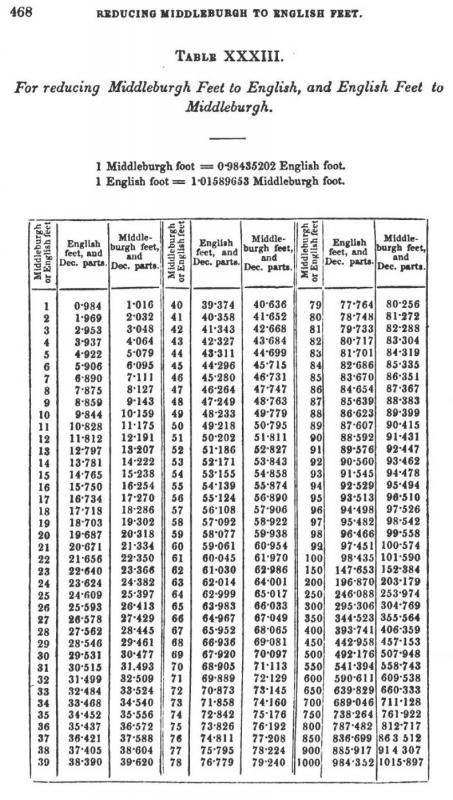
Just as an aid in your future endeavors in converting measurements, I offer the three tables below extracted from the 1838 edition of The Nautical Magazine and Naval Chronicle... a Journal of Papers on Subjects Connected with Maritime Affairs. Simpkin, Marshall & Company. https://books.google.com/books?id=QAV1riauZOQC. Remember - not all feet are created equal! :P :rolleyes: