trippwj
-
Posts
3,156 -
Joined
-
Last visited
Content Type
Profiles
Forums
Gallery
Events
Everything posted by trippwj
-

Metric vs English
trippwj replied to jdiven's topic in Building, Framing, Planking and plating a ships hull and deck
Not hardly, Robin! I have, over my various endeavors for the past too many years of my working life, had the need to work in metric, imperial, and the International System of Units (successor to the metric system). Each has it's place. As others have noted, I can "see" a foot, a yard and so on. I grew up using the imperial system (though I never did get the difference back in the day between a US and a Canadian gallon, but I digress). I like the precision of metric, but do not like the loss of fidelity when converting. Most period ship plans were laid out in some variety of imperial units (although those varied over time and across nations), as were the ratios and derived dimensions (such as keel for tunnage). Those don't always convert so nicely to metric - try converting a number like 127 & 87/95 tun (note this is not to be confused with a weight of a ton/tonne, but rather a cargo capacity of a tun, as determined by the regulations of the time) to a metric equivalent! I guess what I am saying is that, as has been pointed out by others, working in a measurement system that one is familiar with is the most important - fighting a measurement system while also trying to get reasonable measurements for a build is counter-productive. Trying to convert some measurements from old systems to others is, likewise, a potential source for error to creep in. -
Metric vs English
trippwj replied to jdiven's topic in Building, Framing, Planking and plating a ships hull and deck
Ummmm....a lump of coal? Postage due, of course. Taxes and duties payable upon receipt. -
Seeking information on determining load waterline
trippwj replied to trippwj's topic in Nautical/Naval History
The convergence of three separate yet ultimately related concerns resulted in the availability to the shipbuilder of a reasonably accurate method to predetermine the displacement (and thus the LWL) for a ship, whether a war ship or a merchant ship, when fully loaded for the intended purpose. The need to accurately determine the carrying capacity of a vessel (particularly a merchant ship) for collection of duties, port fees and so on. The desire to identify the form of a ship which offers the least resistance to the water. The requirement to identify the shape and form of a ship which provides suitable sailing and handling qualities in all conditions, and to handle the intended sails well. Each of these separate lines of study, coupled with advances in scientific theory and mathematical capabilities, resulted in methodologies that also allowed the shipbuilder to predetermine the displacement from the plans, before construction, rather than having a desired floating level that was dependent on limiting stowage on the ship. The first concern has already been discussed in an earlier post, with incremental changes in methods leading up to the work of Moorsom in the 1850’s, which relied on mathematical approaches developed in response to the other concerns. Efforts to identify the best form of a ship have been ongoing for more than 300 years, and continue today, although with a much higher level of sophistication. As various approaches were developed to identify the best form to part the water, efforts were also undertaken to mathematically explain the empirical results. Euler, Bouguer, Beaufoy and Chapman are among those who developed stability (and displacement) theories based on initial work around the form of least resistance. Earlier work by Pardies, Renaud and others attempted to provide a theoretical framework to describe the motion of a ship – why it could sail against the wind, for example, rather than be pushed hither and yon. This yielded a method to calculate the dérive (drift of ships or lee way) as a point of reference (see figure from Pardies below). From Pardies, I.G. 1673. La statique ou la science des forces mouvantes. Sébastien Mabre-Cramoisy. http://echo.mpiwg-berlin.mpg.de/MPIWG:46XPZMX8.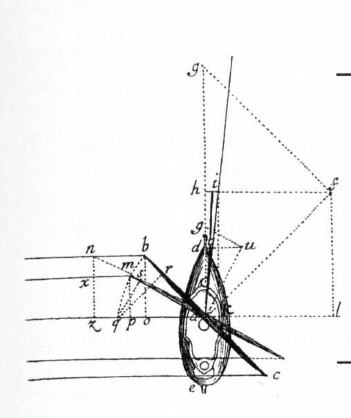
-
Here are a couple of additional places to check for information: Biddlecombe, G. 1848. The Art of Rigging. http://books.google.com/books?id=9RkEAAAAQAAJ. Lever, D. 1853. The Young Sea Officer’s Sheet Anchor; Or, A Key to the Leading of Rigging, and to Practical Seamanship (American Edition). E. & G.W. Blunt. https://books.google.com/books?id=HmJJAAAAYAAJ. Kipping, R. 1853. Rudimentary Treatise on Masting, Mast-Making, and Rigging of Ships. John Weale. ———. 1864. Rudimentary Treatise on Masting, Mast-Making, and Rigging of Ships. Virtue Bros.
-
Sea ports were a much more crowded beast, with individual lines and merchants owning their own pier to recieve cargo. While some may have had cargo handling gear, most did not. When in port, some spars and blocks could be used to hoist cargo, with the occassional temporary spar fitted. The ship needed to be self sufficient as possible, so they had ways to do it. Will do some checking in Crothers, Clark and Lubbock to see what I can find.
-
Daniel - I believe they can be found in Navy Records Society (Great Britain). 1905. Fighting Instructions, 1530-1816 Publications Of The Navy Records Society. Vol. 29. [London]. http://archive.org/details/fightinginstruct00navyuoft. Portions are also available online at The Maritime History Virtual Archives website - “Sailing and Fighting Instructions for His Majesty’s Fleet”, 1775. Accessed May 15. http://www.bruzelius.info/Nautica/Signalling/SFI(1775).html.
-
“At the very forefront of early photojournalism, John Gibson and his descendants were determined to be first on the scene when these shipwrecks struck. Each and every wreck had its own story to tell with unfolding drama, heroics, tragedies and triumphs to be photographed and recorded – the news of which the Gibsons would disseminate to the British mainland and beyond.” https://artblart.com/2014/03/30/photographic-archive-the-gibson-archive-at-the-royal-museums-greenwich-rmg/ The archive of dramatic and often haunting images, assembled over 125 years (1872 to 1997) by four generations of the Gibson family, records over 200 wrecks – the ships, heroic rescues, survivors, burials and salvage scenes – off the treacherous coastline of Cornwall and the Isles of Scilly, was acquired by the RMG at auction in 2013. The collection includes the following: 585 Glass plate negatives (214: 12 x 10in: 8 x 6in) housed in 16 original wooden boxes and one cardboard box. 407 Glass plate copy negatives (6½ x 4¾ in) in 4 cardboard boxes. 179 Glass plate negatives (4¼ x 3¼in). 198 film negatives (5 x 4in) in three boxes. 335 cut film negatives (various sizes) and 39 (35mm) film negatives. 97 original photographs of shipwrecks (silver prints, 12 x 10in) Manuscript ledger by Alexander and Herbert Gibson on the shipwrecks of Cornwall and the Isles of Scilly. A collection of books by John Fowles, John Arlott, John Le Carré, and Rex Cowan on the Gibsons of Scilly, together with newspaper and magazine articles. I am not sure if they are on display at the Royal Museums Greenwich or not, but several may be viewed at the link above. Enjoy!
-
You may want to take a look at the section by Richard Barker, 2003. “Cradles of Navigation” Re-Visited. In Shipbuilding Practice and Ship Design Methods from the Renaissance to the 18th Century: A Workshop Report, 103–163. Preprint 245. [berlin]: Max-Planck-Institut für Wissenschaftsgeschichte. https://www.mpiwg-berlin.mpg.de/Preprints/P245.PDF. He provides several sketches of a variety of launching methods starting on page 155.
-
Nice work, Elijah. To respond to your interrogatories, the stern post and rudder would not be planked. The stern post serves to relieve the ends of the planking (see rabbett), but the copper plating would continue around the post and the rudder would also get coppered .
- 701 replies
-
- 3
-

-
- phantom
- model shipways
- (and 1 more)
-
Looks sweet, Denis. I like the color on the deck.
-
Portsmouth-based aircraft carrier HMS Illustrious up for sale
trippwj replied to dgbot's topic in Nautical/Naval History
Age, my friend, is all relative. In my case, it is relatives that remind me that I am older than dirt... I wonder if they would consider a cross cultural location - she would look awesome moored here in Eastport, or maybe as the border bridge at the narrows in Lubec.... -
You are doing a great job, Elijah. The photos are quite fine enough to see the care you are taking with each step. Until next time -
- 701 replies
-
- 2
-
-
- phantom
- model shipways
- (and 1 more)
-
Seeking information on determining load waterline
trippwj replied to trippwj's topic in Nautical/Naval History
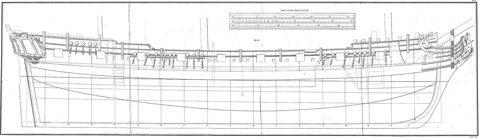
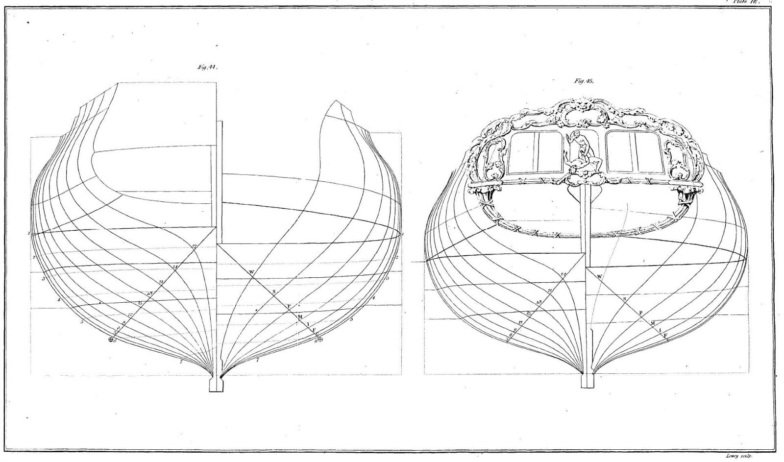
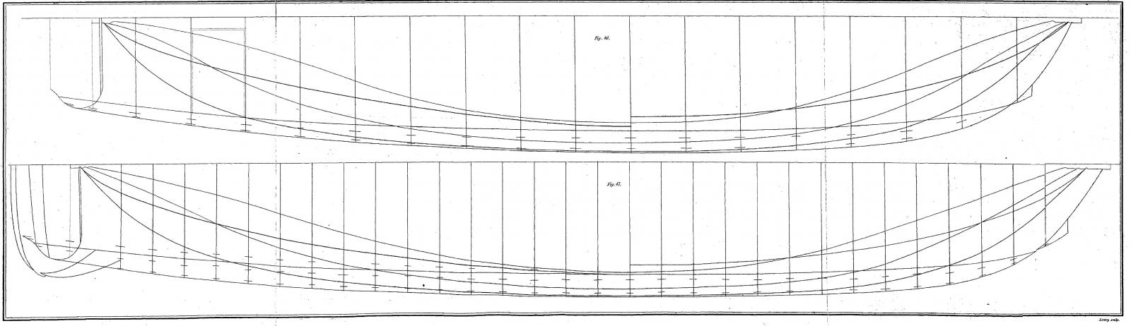
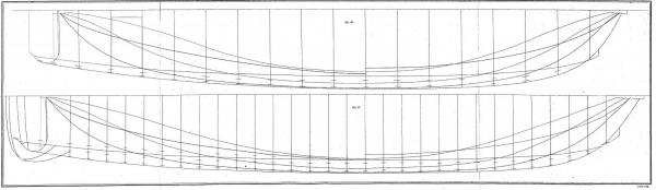
Thought it might be polite to provide the other 3 figures used in the above Scale of Burden for a Privateer.
-
Seeking information on determining load waterline
trippwj replied to trippwj's topic in Nautical/Naval History
Chapman's work is, indeed, of great interest, and will represent a seperate posting when the time comes - I am working with the Inman translation of his Tractat om skeppsbyggeriet, first published in 1775 to complement the author's Architectura navalis mercatoria. The plates and figures related to many of the calculations are included, and detailed methods discussed. Additionally, it is long out of copyright so the figures and text are freely available for quotation and so on. I am working though some of his details and it is quite interesting! As one tidbit: To construct from hence a scale of burden. (182.) Draw two lines perpendicular to each other, the one in a horizontal direction, the other in a vertical direction; make on the horizontal line a decimal scale at pleasure to represent lasts, and on the vertical another scale of feet also at pleasure, as is seen in Fig. 50. Below the horizontal line and at the distance from this superior line of 1.62, 3.24, 4.28, 6.48, 8.1, 9.72 and 11.2 feet, draw parallels thereto. On the scale of lasts, take the quantities, which have been found, in lasts 45.16, 85.89, 120.88, 149.75, 171.45, 184.6 and 189.58; set off these quantities on the corresponding horizontal lines, from the vertical line. Through all the points so determined pass a curve, and you will have a scale of solidity. The horizontal scale is in French tons, English tons, and Swedish lasts. The method of using the scale is this. The line a b (NOTE 53.) on the sheer plan is the load water-line, the privateer being laden. Suppose that the water-line before it is entirely laden, were cd; then the distances ac, bd are taken, which by the scale of the plan give 4 feet 1 ½ inches and 5 feet 1 ½ inches; these two quantities are added, and half the sum is taken, 4 feet 7 ½ inches. Take this quantity 4 feet 7 ½ inches on the scale of solidity" you will have e g, which must be transferred perpendicularly to the line e f, until it meet the curve in h. From h draw the line hi perpendicularly to f e, or what is the same thing, parallel to e g; this line marks on the scale of lading the weight, which must be put on board to bring down the ship to the line a b, namely, 175 Swedish lasts. (183.) If the ship be quite light, one may in this manner find the lading, which it can take; or if the water-line of a ship ha~. been once observed, supposing another to be found, one may be able" by means of the said scale, to obtain the weight which the ship has taken on board, or of which it has been discharged, to render it so much more brought down, or more raised.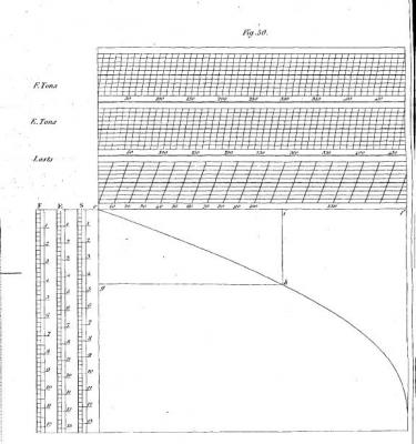
-
Seeking information on determining load waterline
trippwj replied to trippwj's topic in Nautical/Naval History
This approach to ship design was fairly common in the 15th and 16th centuries. Bellabarba (1993) observed that Many ships have been built, right up to our times, using a few measurements and proportions between the main parts, and the 'master's eye' dealing with all the rest. Although this method provided respectable, indeed admirable, results, it did not permit a successful example to be reproduced exactly, nor any mistakes to be corrected intelligently. Any possibility of making progress depended on individual masters' memories and insight and their willingness to share their experience with others (colleagues or successors). With this intuitive yardstick, it was impossible to build a series of identical units which was particularly essential for the fleets of Mediterranean galleys and likewise to prefabricate parts of the hull. But, in contrast, the ancient method of design allowed a hull shape to be reproduced exactly the same as any other one or its characteristics to be subtly varied by means of a set of 'rules' which, in addition to simple measurements (length, height, width, proportions etc.) included indications for defining the hull curves geometrically. These instructions could be memorised and easily communicated, with no need for either drawings or mathematical calculations. This distinguishes the ancient method described here from all the other, more or less contemporary ones, based on mere intuition (the 'master's eye') or the ribbands, which we shall come back to later. The set of 'rules' were numerical instructions which could be used directly in the yard during shipbuilding. So the method could be described as a 'method of rules' as opposed to the more recent method of drawings. Bellabarba, Sergio. 1993. “The Ancient Methods of Designing Hulls.” The Mariner’s Mirror 79 (3): 274–92 . doi:10.1080/00253359.1993.10656457. Loewen (1998) offered a brief description of the process: Three major steps made up the ship carpenter's process of designing a hull. First, he worked out the four basic dimensions of the hull: its breadth, its keel, its length from stem to sternpost and its depth of hold. These dimensions mirrored those used by ship surveyors to gauge a ship's tonnage and, in practice, allowed a carpenter to convert to a merchant's desire to build a ship able to carry a certain tonnage of goods into real measures. Second, within the parameters of the breadth and the depth of hold at midship, the carpenter worked out the shape of the master frame, using as his fundamental elements a series of five tangent lines and arcs: the floor line, the bilge arc, the futtock arc, the arc at the greatest breadth and the tumblehome line. He then devised a master mould from this shape, and marked off the points on the mould at which his lines and arcs touched. Third, using the master mould, he worked out the shape of frames fore and aft of the master frame by means of three systematic adjustments to the master mould, namely: the rising of the floor, the narrowing of the floor and adjusting the aspect of the frame from the bilge upwards. Loewen, Brad. 1998. “Recent Advances in Ship History and Archaeology, 1450-1650: Hull Design, Regional Typologies and Wood Studies.” Material Culture Review / Revue de La Culture Matérielle 48 (1). http://journals.hil.unb.ca/index.php/MCR/article/view/17791. In A Treatise on Shipbuilding: And a Treatise on Rigging, Written about 1620-1625, the anonymous author offers a detailed description of the process of “whole moulding”: 'Suppose I would mould out the 20th bend of timber aft: 1st: I strike a ground line upon the foot of the timber and cross it at right angles with a middle line for the depth. 2nd: I set off the rising of that bend from the ground line, at the length it is marked upon the floor mould. 3rd: I seek the depth of that bend, which set off from the rising line I draw a parallel to the gound line for the breadth. 4th: I take the narrowing aloft out of the greatest breadth and at that breadth draw a parallel to the middle line. 5th: I set the narrowing alow upon the middle line of the timber and score out by the mould both within and without the frame of the mould. 6th: I bring down the sine mark of the lower part of the futtock to the haleing down thereof upon the wrong head and score out that part of the futtock. 7th: I bring down the lower end of the upper futtock to the haleing down marked upon the lower part, and score out the upper part of the futtock. 8th: I put up the top timber upon the end of the futtock according to the mark of putting up, that it may fit his breadth at the upper surmark, and score aut by it the top timber mould. And so is the whole bend truly moulded with all his parts'. Salisbury, W, and R. C Anderson, eds. 1958. A Treatise on Shipbuilding: And a Treatise on Rigging, Written about 1620-1625. Occasional Publication No. 6. London: Society for Nautical Research. -
Seeking information on determining load waterline
trippwj replied to trippwj's topic in Nautical/Naval History
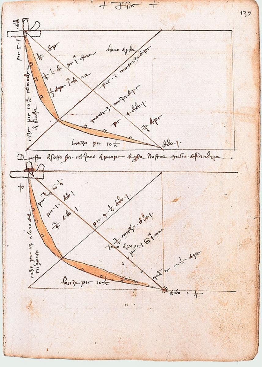
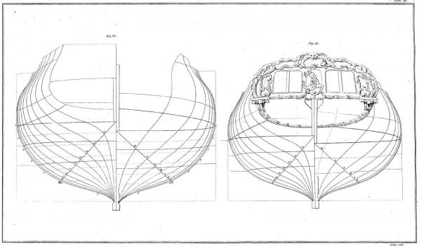
Having stuck my neck out by making this broad a statement, let me offer some of the reasons behind this assumption. While the processes and methods used to design vessels are as old as the use of ships, for the purposes of this discussion I am going to limit the time frame to about 1400 through 1800. This period includes a variety of design and construction methods, as well as increasing awareness of the science of flotation and resistance. The upper end point is very carefully chosen as representing the point where, particularly in Great Britain, there was a paradigm shift about to occur in how the ship builder thought about the form and design of the ship. Sepping’s bow, diagonal riders, stability calculations, the advent of steam and iron construction – all of this and more influenced a paradigm shift during the first half of the 19th century, worthy of study separate from the earlier periods. The modern approach to designing a ship is generally thought of in terms of measured drawings and plans drawn on paper and then transferred to the mould loft floor. These drawings were used to determine the exact shape of the ship - before the start of building. The drawings were also used to store good designs both for review and reuse. Neither measured plans nor even the technique for making them existed in the Middle Ages. Ship design, in terms of determining final dimensions, was carried out in the shipyard while the ship was being built. While the overall shape of the vessel was easily envisioned, determining the dimensions of hundreds if not thousands of individual parts that had to be cut from timber and assembled together was the challenge. What methods were used to store the “good” designs and retrieve them for later use? In 1434, Michael of Rhodes sat down to write out the manuscript for which he is remembered. He recorded his full name of Michalli da Ruodo twice in the 440-page text. In his treatise on shipbuilding, he provides two approaches to the challenge of ship design. For the types of ships built in private shipyards, he describes a system based on a proportional approach; for the galleys built in the state-run Arsenal, his approach reflects the recording of actual measurements on paper. Michael's manuscript contains some of the earliest known ship-design drawings, marking an early stage in the transfer of design from the shipyard to the drawing office. Most of a galley's frames were shaped by proportion, or "moulded." The geometry, however, did not extend all the way to the bow and stern which were shaped by hand, using thin wooden battens, or ribbands, as guides. The shapes of most of a galley's frames were determined by proportion, but the geometry did not cover the shape of the bow or stern. These were determined in the yard, using string to get the proper curve. This drawing was intended to illustrate part of the process. The top diagram provides dimensions relating to the shape of the stempost; the bottom diagram, dimensions relating to the stern. Source: Stahl, Alan M., ed. 2009. The Book of Michael of Rhodes: A Fifteenth-Century Maritime Manuscript, Vol. 2: Transcription and Translation. Trans. Franco Rossi. Vol. 2. 3 vols. Cambridge, Mass: The MIT Press. Also see The Michael of Rhodes project. Accessed April 28, 2016. http://brunelleschi.imss.fi.it/michaelofrhodes/index.html.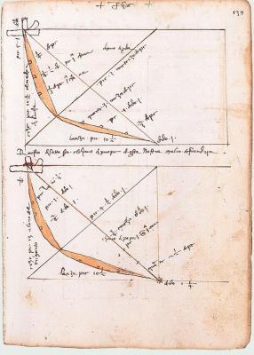
-
Seeking information on determining load waterline
trippwj replied to trippwj's topic in Nautical/Naval History
John – You bring up some interesting considerations – thank you! One of the aspects that comes out in trying to research this topic, esoteric as it may be, is that there was a distinction to be drawn between the theorist and the builder. Many of the mathematicians (Bernouli, Euler, Fourier, Newton etc.) were mathematical theorists. They developed methodologies and approaches to the task, yet were not ship builders themselves. Nor, for that matter, did they design ships. There was, of course, the mathematically oriented ship builder – people like Deane, Pett, Baker (and Tom Wells) and Chapman. They not only designed and built ships, but also applied the mathematical theories in their work. Now we come to the pure ship builder of old. They had enough mathematical background to determine the measurements of components (often based on simple rations, arcs and so on – see Rees and Steel, publishing someone else’s narrative, for examples), but did not apply the mathematical theories to the effort. The frustration in English naval architecture can be found in the publications by The Society for the Improvement of Naval Architecture (Society for the Improvement of Naval Architecture. 1791. An Address to the Public, from the Society for the Improvement of Naval Architecture. Instituted 14th April, 1791. https://archive.org/details/someaccountinst00unkngoog.) To promote this important object as effectually as possible, the society purpose to encourage every useful invention and discovery as far as shall be in their power, both by honorary and pecuniary rewards.—-They have in view particularly to improve the theories of floating bodies and the resistance of fluids—to procure draughts and models of different vessels, together with calculations of their capacity, centre of gravity, tonnage, &c. —to make observations and experiments themselves, and to point out such observations and experiments as appear best: calculated to further their deigns, and most deserving those premiums which the society can bestow. But though the Improvement of Naval Architecture in all its Branches be certainly the principal object of this institution, yet the society do not by any means intend to confine themselves merely to the form and structure of vessels. Every subordinate and collateral pursuit will claim a share of the attention of the society in proportion to its merits; and whatever may have any tendency to render navigation more safe, salutary, and even pleasant, will not be neglected. We also find, in 1860, the Reverend Wooley reflecting on the progress and state of mathematics in Naval Architecture (Wooley, J. 1860. On the Present State of the Mathematical Theory of Naval Architecture. In Transactions of the Royal Institution of Naval Architects, I:10–38. The Institution. https://books.google.com/books?id=xR-oHqNU7RIC) In former times, the constructors of ships in the Royal Navy were restricted to certain relative dimensions of length, breadth, and depth, which in fact gave a small amount of natural stability, and necessitated a recourse to ballast. Sir William Symonds was the first surveyor of the Navy who obtained the power of building ships without those unnatural restrictions, and he gave considerable beam to his vessels, and with it great natural stability, and so was enabled to reduce very materially the quantity of ballast--a very important gain. Whatever may be thought of the form of his vessels in other respects, it cannot be denied that, so far as increasing beam and diminishing ballast are concerned, he effected an immense improvement in the vessels of the Royal Navy. The scientific constructor would do well, however, not to confine his investigations to mere formulae derived from analytical processes, and to inferences drawn from them; but he would derive immense information, and add most materially to the breadth and practical value of his views, by examining from first principles, and in a more geometrical method, the several elements on which stability may be made to depend. In this way he may gain most valuable experience as to the twofold nature of stability which I have already indicated. Interspersed among a multitude of period writings are observations concerning the limited mathematical skills of most ship builders and shipwrights. Indeed, more recent scholarly research has drawn the similar conclusions (see, for example, Tebeaux, E. 2008. Technical Writing in English Renaissance Shipwrightery: Breaching the Shoals of Orality. Journal of Technical Writing and Communication 38, no. 1: 3–25. http://jtw.sagepub.com/content/38/1/3.) The information was there, but most of those who were in a position to use it and benefit from it were not trained in how to use it. Time for a working hypothesis. The central question: At what point did shipwrights shift from marking a load waterline based on where they felt it should be to determining where the load water line would be based upon the form and structure of a vessel. The Hypothesis: Early shipbuilders developed their methods and designs based largely on trial and error. As the size of vessels increased, methods became more formalized in an attempt to maintain the relationship between form (shape), function, and performance. Systems such as “whole moulding” and “shell first” construction were developed over many years of trial and error, to guide a builder in forming the body of a ship. No attempt was made to predetermine accurately the immersion of these vessels, but rather institutional knowledge (what had worked for similarly built vessels) guided the builder. -
Very impressive! You are going to need a bigger house to keep this big girl in appropriate style! Enjoy your vacation, kind sir. Are you bringing the gnomes with you?
- 1,616 replies
-
- 5
-
-
- caldercraft
- agamemnon
- (and 1 more)
-
I am still trying to locate the 1914 Admiralty investigation - have found a snippet or two, but not yet able to locate the full report. Will try again in the morning - time for me to tuck it in. Only have the one day off each week (Sunday) from work, so try to get up early to make the most of it! Dafi - let me know if any of the documents listed are helpful. Will keep searching for the Admiralty one from 1914.
-
Daniel - I think this may be at least a couple of the documents to which Robin was referring. James, W. 1826. The Naval History of Great Britain, from ... 1793, to ... 1820, with an Account of the Origin and Increase of the British Navy. Vol. 4. https://books.google.com/books?id=NpF7KhRs8RcC. Desbrière, E. 1901. Projets et tentatives de débarquement aux Iles britanniques: 1793-1805. Vol. 1. Chapelot. https://books.google.com/books?id=NiMEn3UHHIgC. Desbriere, E. 1933. The Naval Campaign of 1805: Trafalgar, Vol. 1: Text. Trans. Constance (translator) Eastwick. Clarendon Press. https://books.google.com/books?id=tMOoYgEACAAJ. Additional volumes are listed on that same page.
-
Jud - Gun Port stops function much the same as the soffit (stops) on modern doors. If modern carpenters, with thousands of years of institutional knowledge behind them, not to mention untold bazillions of doors installed, have found the stop an effective way of ensuring that a simple household door doesn't move further into the opening than intended, why should we think a ships carpenter, working in a non-planar building surface, would be so presumptuous to think that the port lid (all 110 or so for the largest ships) would fit right, every time, at sea or anchor? That series of holes in the side was the Achilles heel, so to speak, of nearly every war ship afloat. In a rough sea, if a port broke open (the port lid pushed through the port), the volume of water admitted could, in a short time, create major stability issues as the vessel settles lower due to water accumulation in excess of the pump ability to remove. In terms of protecting the interior planking from the gun, that was not a major concern. The waterway was designed as the stop for the carriage wheels. The pressure of the gun carriage against the side was planned for - that was how a gun was intended to be used and stored. The bigger design challenge was to come up with a design for the eye bolts used to anchor the various gun tackle to withstand the recoil after firing. The gun, accelerated to a velocity due to recoil, wants to stay moving in that direction at that velocity. Inertia (the resistance of any physical object to any change in its state of motion) and momentum (product of mass and velocity) mean that it takes a large or prolonged force to bring it to a stop afterwards. That force is applied by the various tackle, all anchored to very small sections of the hull by the eye bolts.
-
Interesting thought, Dan. I can come up with several definitions (interestingly, none in english) that describe it as essentially a rudder angle (tiller angle) indicator. The other definitions all describe a method using lenses to determine alignment, also for use in fitting spectacles. Will keep looking.
-
Were the anchors rigged so both were raised/lowered at the same time? Nope - as the references provided describe, only one at a time. These were brutally heavy with massive cables some 22" or more in curcumference. Man handling these into the cable tiers was anything but simple, as these thick cables were not particularly flexible. Add to that the capstan could only bring one at a time due to the weight and technology. The above, of course, covers weighing (raising) the anchor. Setting the anchor is a whole 'nother adventure in semi controlled violence!
-
Welcome back, Elijah. Hope you had a good time! What part of Virginia did you visit (I think I missed that post....)
- 701 replies
-
- 3
-
-
- phantom
- model shipways
- (and 1 more)
-
She is a beauty, Sjors. Your zoo is doing admirable work!
- 1,616 replies
-
- 6
-
-
- caldercraft
- agamemnon
- (and 1 more)