trippwj
-
Posts
3,156 -
Joined
-
Last visited
Content Type
Profiles
Forums
Gallery
Events
Everything posted by trippwj
-
 Indeed, welcome back. Hopefully we kept things tidy enough while you were out (Mark brought his shop vac in to clean just last year...).
 -
"Gunnery notes" from William Rivers (*1755, †1817)
trippwj replied to dafi's topic in Nautical/Naval History
The manuscript in question appears to be at the Royal Navy Museum Portsmouth, according to the Cole citation. I have not yet been able to track it down any further. Cole, Dr Gareth. 2009. “Royal Navy Gunners in the French Revolutionary and Naploeonic Wars.” The Mariner’s Mirror 95 (3): 284–95. doi:10.1080/00253359.2009.10657104. https://ore.exeter.ac.uk/repository/handle/10036/3762 Also see the following book by Cole where the Rivers manuscript is again mentioned somewhat prominently. Cole, Gareth. 2012. Arming the Royal Navy, 1793-1815: The Office of Ordnance and the State. London; Brookfield, Vt.: Pickering & Chatto. Of course, i should have clicked your links first - I would have realized you already had the link to the Mariner's Mirror article. -
location of stud sails (stuns'l) when stowed
trippwj replied to timboat's topic in Masting, rigging and sails
Anderson is still copyright protected with no "legal" pdf versions found. It can be purchased from Amazon and others either as a print or ereader version quite inexpensively. Also look into the original version The Rigging of Ships: in the Days of the Spritsail Topmast, 1600-1720 Could you describe the 1719 document better (or is that a time frame of interest?) I have a few that give some information around that time frame, but none specific to the 1719 Establishment (which, as I recall, just dealt with the desired principle dimensions). -
American sailing warships with no plans or records
trippwj replied to CharlieZardoz's topic in Nautical/Naval History
Let me just interject a word of caution concerning the semantics of the time. It is important to keep in mind that for the period under discussion (1770 - 1840), the term "Sloop of War" had absolutely nothing to do with the rig the vessel carried. A "Sloop of War" was anything smaller than the smallest rated war ship (generally a 20 gun 6th rate). In the American nomenclature, the early definition was quite similar. The rig was immaterial - there were Brig Sloops of War, Schooner Sloops of War. During the period of interest, terminology concerning the rig was much less precise and varied regionally. Standardization would have to wait the development of the more bureaucratic navy during the mid 19th century.- 401 replies
-
- 6
-

-
- John Adams
- Alliance
- (and 3 more)
-
location of stud sails (stuns'l) when stowed
trippwj replied to timboat's topic in Masting, rigging and sails
A couple of more describing setting the studding sails. From Bushell, Charles. 1856. The Rigger’s Guide. http://archive.org/details/bub_gb_FF8BAAAAQAAJ. Pages from 1856 The_Rigger_s_Guide_and_Seaman_s_Assistant_Bushell.pdf Also, Martelli, Charles. 1838. The Naval Officer’s Guide for Preparing Ships for Sea ... Second Edition. Richard Bentley. https://books.google.com/books?id=0LJWAAAAcAAJ. Pages from 1838 The_naval_officer_s_guide_for_preparing_martelli.pdf -
location of stud sails (stuns'l) when stowed
trippwj replied to timboat's topic in Masting, rigging and sails
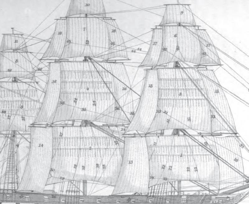
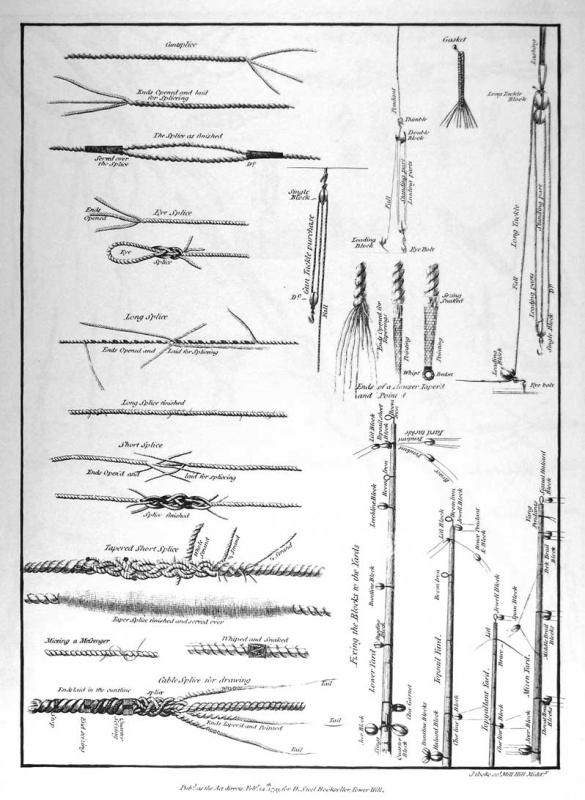
The attached from Lever (1853) and Biddlecombe (1848) may be of some use for you. Based on what I have seen, studding sails would be kept below deck in the sail locker and brought out when needed - much like many of the stay sails &c. which were only bent when needed. Lever, Darcy. 1853. The Young Sea Officer’s Sheet Anchor; Or, A Key to the Leading of Rigging, and to Practical Seamanship (American Edition). E. & G.W. Blunt. https://books.google.com/books?id=HmJJAAAAYAAJ. Pages from 1853 The_Young_Sea_Officer_s_Sheet_Anchor_LEVER.pdf Biddlecombe, George. 1848. The Art of Rigging. http://books.google.com/books?id=9RkEAAAAQAAJ. Pages from 1848 The_art_of_rigging_Biddlecombe.pdf Also, the following from Steel, David. 1796. The Art of Rigging. David Steel. https://books.google.com/books?id=slnnnAEACAAJ&hl=en. Pages from 1796 TheArtofRigging_Steel.pdf Plate II from 1796 TheArtofRigging_Steel.pdf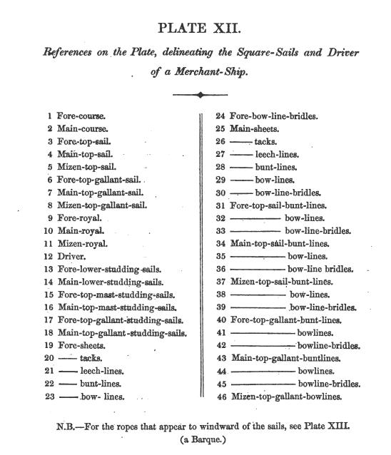
-
Seeking information on determining load waterline
trippwj replied to trippwj's topic in Nautical/Naval History
I'll see what I can find. The 30 gun is actually French, Duhamel du Monceau treatise of 1754, translated and included in Mungo Murray's treatise. I need to fix that in the table! -
See info here:http://www.awiatsea.com/Privateers/R/Rattlesnake%20Massachusetts%20Ship%20[Clark].html Not sure the source used.
-
Seeking information on determining load waterline
trippwj replied to trippwj's topic in Nautical/Naval History
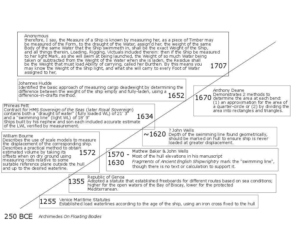
Here is a new attempt at a timeline of developments relative to the overall topic. Would appreciate any recommendations - is it too cluttered or hard to read? Note I still have information to add for the period after 1707. THANK YOU!!!
-
Looks good, Sjors. I am, however, going to show my apparent ignorance by asking what that is attached to the mast in the second photo...almost looks like an electrical device, but I am pretty sure that isn't true! Merry Christmas to you & Anja!
- 1,616 replies
-
- 4
-
-
- caldercraft
- agamemnon
- (and 1 more)
-
Wow - missed the start on this one! Looks like a nice fun build for you. Now that I have found it, will stay for the show! Hope you are doing well, Denis!
- 453 replies
-
- 7
-
-
- thermopylae
- sergal
- (and 1 more)
-
Very nice work, Elijah. The bowsprit looks quite neat. I had forgotten how tall that lower mast is!
- 701 replies
-
- 7
-
-
- phantom
- model shipways
- (and 1 more)
-
Seeking information on determining load waterline
trippwj replied to trippwj's topic in Nautical/Naval History
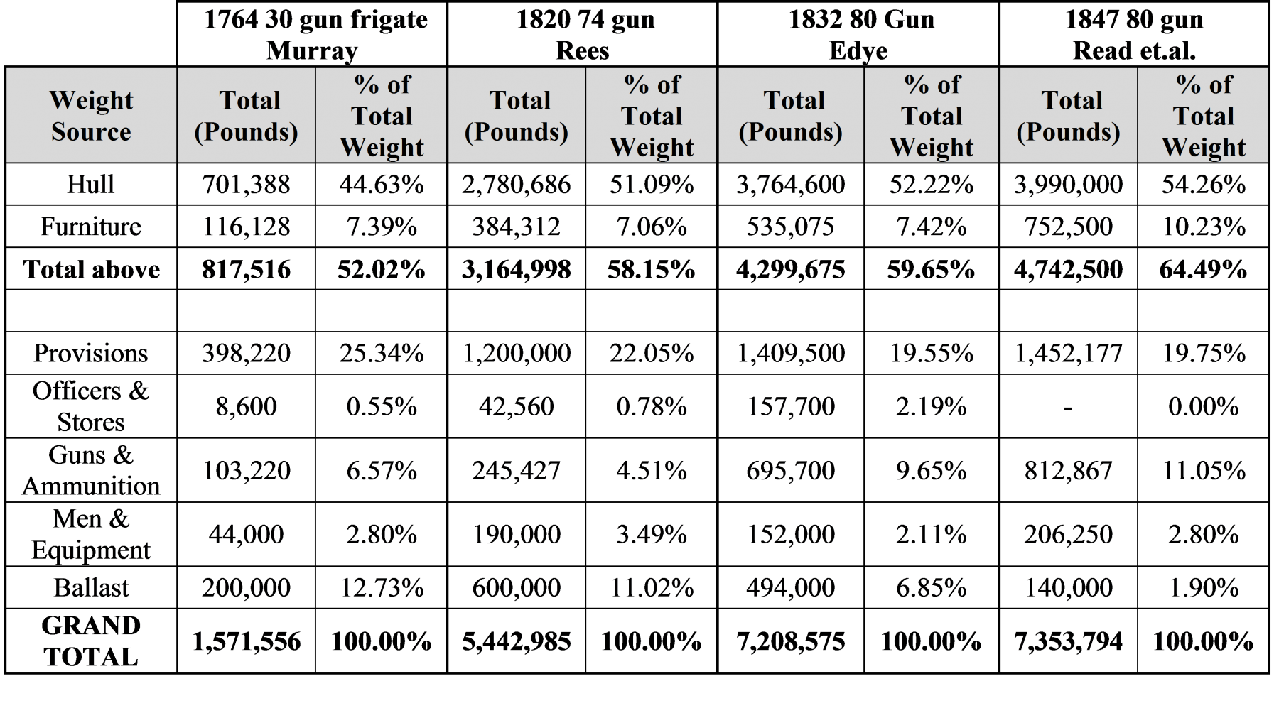
Whilst working my way through various contemporary treatises, some more legible than others, it occurred to me that for the application of the Archimedes Principle to be effective, it was necessary to be able to estimate the actual weight of the vessel before it was constructed. I took a detour, as it were, to search out some examples where estimates of a ships weight were given. The four provided below are just representative cases – there are others. It is interesting to see how the relative proportion of each part of the ship has, surprisingly, remained rather consistent across classes and decades. For example, in 1754 the hull was 44,6% of the total weight for a 30 gun frigate, and in 1847 (with much more accurate methods used) it was 54.3% of the total weight for a proposed 80 ship. Sources: Murray, Mungo. 1754. A Treatise on Ship-Building and Navigation. In Three Parts, Wherein the Theory, Practice, and Application of All the Necessary Instruments Are Perspicuously Handled. With the Construction and Use of a New Invented Shipwright’s Sector ... Also Tables of the Sun’s Declination, of Meridional Parts ... To Which Is Added by Way of Appendix, an English Abridgment of Another Treatise on Naval Architecture, Lately Published at Paris by M. Duhamel. London, Printed for D. Henry and R. Cave, for the author. https://archive.org/details/treatiseonshipbu00murr. Rees, Abraham. 1819. Article on Shipbuilding in The Cyclopædia; Or, Universal Dictionary of Arts, Sciences, and Literature. Vol. 32. London : Longman, Hurst, Rees, Orme & Brown [etc.]. http://archive.org/details/cyclopaediaoruni32rees. Edye, John. 1832. Calculations Relating to the Equipment, Displacement, Etc. of Ships and Vessels of War. Hodgson. Read, Samuel, Henry Chatfield, and Augustin Francis Bullock Creuze. 1847. Reports on Naval Construction, 1842-44. W. Clowes.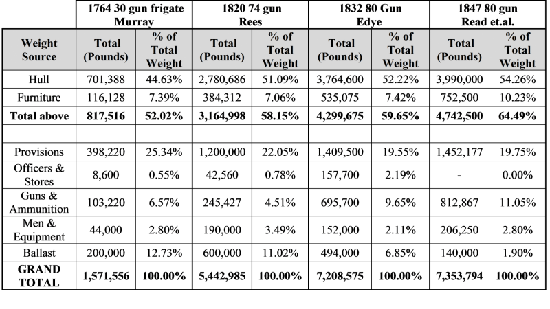
-
I suspect the green inner bulwarks was not done with these beasties. The Revenue Marine (which preceded the Navy by a few years) was a much more subdued branch - their duties, specifically assigned to the cutters and their crews as legislated by Congress and expounded by Hamilton included: Boarding incoming and outgoing vessels and checking their papers (ownership, registration, admeasurement, manifests, etc.); Ensuring that all cargoes were properly documented; Sealing the cargo holds of incoming vessels; Seizing those vessels in violation of the law. They were also tasked with a number of other duties that were not related to protecting the revenue. These included: Enforcing quarantine restrictions established by the federal, state or local governments; Charting the local coastline; Enforcing the neutrality and embargo acts; Carrying official (and unofficial) passengers; Carrying supplies to lighthouse stations; Other duties as assigned by the collector. Their primary purpose, however, was to protect the revenue of the United States by deterring smuggling. The funding for these cutters was tiny - around $1,000 each for the original 10 cutters; while there is sparse detail, without digging into legislative records, that is, the available information indicates that in the 1816-1825 period when these were built, the cost was less than $3,000 each (actually, the Active (1816) shows a cost of $1,390, while the bill for the Detector and Search totaled $12,500.) The mission post- Second War with Britain expanded to include anti piracy, but retained the former anit-smuggling and revenue protection missions. They were still extremely active in the anti-smuggling role during this period. The area where I live, Moose Island and Eastport, was the last US Territory occupied by the British following the war and was not returned to the US until 1818 (Statehood followed in 1820). Smuggling was a way of life before the war, and following the departure of those pesky British it resumed once more. There are many tales from this region of the hatred felt toward the Cutter Detector by those in the Machias Bay area. The office of Collector of Customs in Eastport was a rather Dangerous position. Unfortunately, most of the older records from the Customs House were either captured by the British in 1814 or burnt in one of the 2 great fires of the late 19th century. My point, though, is that the overall cost was low to build and equip these vessels - they would not waste much money on expensive paint schemes. Basing the color of a cutter on Naval paint schemes is, for this period, probably not accurate. The cutter role required stealth - they needed to remain nearly invisible to the smuggler to intercept them at night. Often they would lay-up in small coves or bays to wait for the smuggler. The anit-piracy role required similar actions, hence an incentive for more subdued colors. As to the green inner bulwark, another probably not. Even the Constitution historians (including experts such as Tyrone Martin) debate how accurate the green is for the early 19th century. I think you would be fairly accurate to go with tarred or black for the outer hull above the waterline, probably coppered below. Perhaps a narrow white or yellow ochre stripe along the hull, inner bulwarks either natural or whitewashed. Not much decoration, very utilitarian to match the role.
- 362 replies
-
- 6
-
-
- active
- revenue cutter
- (and 1 more)
-
While I am still looking, a cursory search shows that the Nonsuch was actually not a Revenue Cutter. She appears to be a privately built schooner initially issued a letter of margue as a privateer before purchase into the Navy. Her exploits are covered in Dudley, William S., ed. 1992. The Naval War of 1812: A Documentary History; Volume II. 1813. Vol. II. IV vols. Government Printing Office. http://ibiblio.org/anrs/1812.html Fortunately, there is a good index available where entries for each ship (and many Captains, for that matter) are listed.
- 362 replies
-
- 4
-
-
- active
- revenue cutter
- (and 1 more)
-
The Mystic items are listed as ships plans - but that is all the info I have on them. Here is the guidance on purchasing copies: For Builders & Modelmakers Full size black-and-white copies of plans in the collections are available for the non-profit use of owners, builders, restorers, modelmakers, researchers and others. These prints are produced from digital scans of the original plans. Prices Sets of plans from the Ships Plans Store are priced as marked. [note - the Doughty plans are not listed with a price. May be able to contact them for more information] Limitations These copies are sold as historical documents, and Mystic Seaport makes no warranty as to the accuracy of the plans or their usefulness for a specific purpose. They are not certified by Mystic Seaport for construction. Plans are sold for research, boat or model building only. For commercial use of any kind and for reproduction in any form you must contact the Ships Plans office in advance at 860-572-5367. If you are interested in more than what you find in our Ships Plans Store https://store.mysticseaport.org/ships-plans/ , visit the site for the Daniel S. Gregory Ships Plans Library at Mystic Seaport. The Library contains 100,000+ naval architectural drawings from 1827-2004, grouped into collections based on their source. Many of the collections within the library have an online finding aid that lists all of the vessels and sets of plans in that collection. https://store.mysticseaport.org/ships-plans/contacts
- 362 replies
-
- 5
-
-
- active
- revenue cutter
- (and 1 more)
-
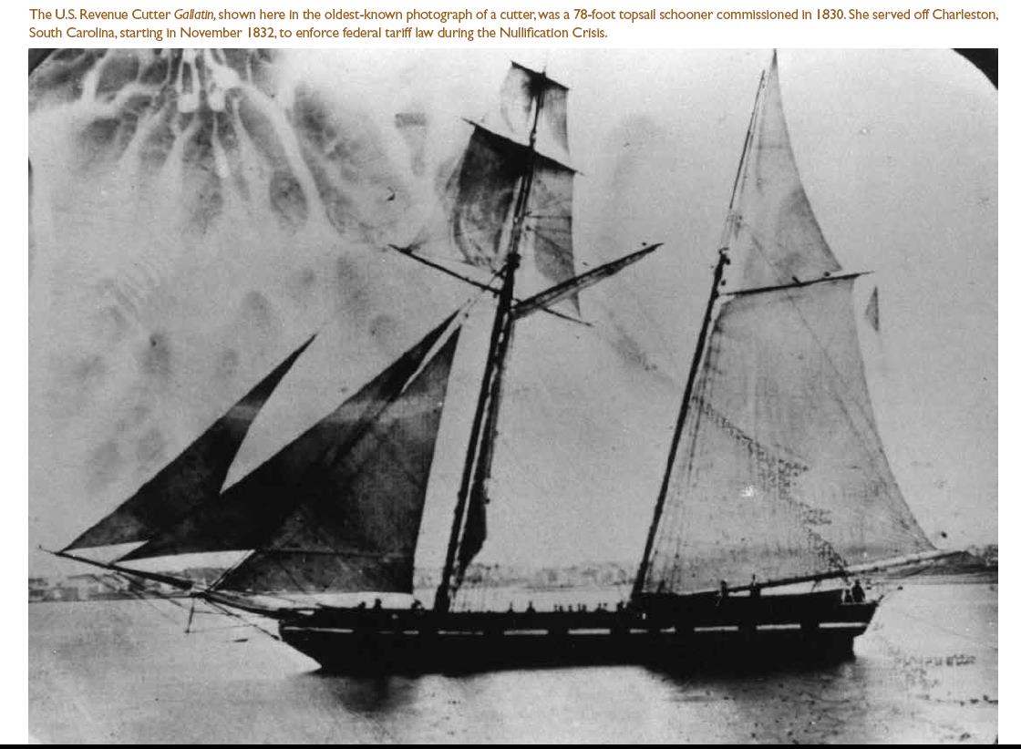
Tracking down these Doughty Cutters has been an on again off again project for me over the past few years. Have you looked into what you can learn about the following in the Coll. 52, Daniel S. Gregory Ships Plans Library, Mystic Seaport Museum, Inc. http://research.mysticseaport.org/coll/spcoll052/ 52.33 UNIDENTIFIED; 60 ft. U. S. revenue cutter Designer, Willliam Doughty; Builder unknown; 1825 52.34 UNIDENTIFIED; U. S. revenue cutter Designer, Willliam Doughty; Builder unknown; 1815 52.36 UNIDENTIFIED; U. S. revenue cutter Designer, Willliam Doughty; Builder unknown; 1815 The photo below is from Prologue | Fall 2014, available at https://www.archives.gov/files/publications/prologue/2014/fall/cutters.pdf (NOTE - this would be the follow-on to the 1815 Gallatin - somewhat larger at about 80' and 112 tons). The apparent color scheme may aid in your estimation of what was the common practice in the early to mid 19th century.

- 362 replies
-
- 4
-
-
- active
- revenue cutter
- (and 1 more)
-
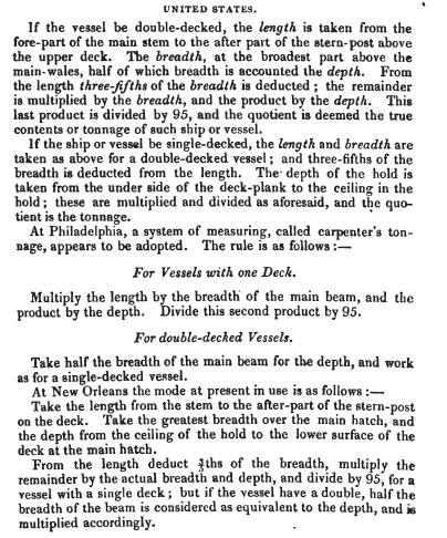
I pulled some information on the various names you suggested from other parts of the USCG Historian website (see attached). US Coast Guard History Extracts.pdf As far as the "tonnage" (or, as listed on the USCG information sheets for each vessel, "displacement"), I would not get too focused on that as a precise measure - close is close enough from that time period. Of interest is that the Dallas (1816) is listed as precisely the Doughty tonnage - that is probably drawn from Canney (who relied on Chapelle). The US had a mish mash of tunnage laws and regulations at this time - and much variance between ports. Here are but a couple of examples: 1789 U.S. Stat. L, vol. I, p. 55. United States Tonnage Law, passed 1st September 1789. Known as 'Custom House Measurement'. The length was measured from the fore part of the main stem, to the after part of the sternpost, above the upper deck. From this, 3/5 of the beam was deducted in order to obtain the Length for Tonnage (LT). The breadth ( B ) was measured at the broadest part above the main wales. The depth (D) varied. In single decked vessels the depth was measured from the underside of the deck plank to the ceiling in the hold. In ships with two or more decks, the depth was taken to be half the breadth. In all vessels, the formula used was (LT x B x D)/95 1793 Joshua Humphreys, War Department Papers TNB06 describes how the tunnage of his frigate designs was determined. In the first place to find the length of straight rabbet forward you take 3/5 of the beam as usual from that point to the after part of the stern post allowing its width for measurement not to exceed 1/12 of the beam. That length being determined you then multiply it by the length of beam & that product by the height of the gundeck beam amidship on the top of the beam added to half of her waste amids which last product divide by 95 which will give the number of ton required. Humphreys also offers the following: Rules for the measurement of ships & vessels to be built in Philadelphia as agreed on by the Shipwright Society January 3rd, 1811 For all plain built ships with two decks - allow 3/5 of the extreme breadth for the rake of the stem beginning to measure twelve inches before the rabbit at the middle of the rale with should determine the point of straight rabbit forward; from that point to the after part of the stern post allowing one twelfth of the extream breadth for its width clear of the rabbit shall determine the length of the keel for tonnage. The breadth for tonnage shall be ascertained from the inside of one rale to the outside of the other in the widest part of the vessel. The depth of hold from the top of ceiling next the keelson (allowing the strake next the keelson the same thickness as the running plank) to the top of after beam amidships & the height between deck from plank to plank amidships then multiply the length of keel by the extream breadth & that product by the depth of hold added to half the length between decks which last product divided by 95 shall give the number of tons required. Single decked vessels on the double deck plan with about 12 inches waist, when depth does not exceed half the extream breadth, measure & multiply length & breadth as above & that product is the depth but when the depth exceeds half the extreme breadth then add that difference to half the extreme breadth for the multiplier for measurement & divide as aforesaid. Single deck vessels primed out on the wales measure & multiply length, breath & depth & divide as above. Frigate built with two flush decks long quarter decks & forecastle with a tier of ports - multiply the length by breadth & make product by the height of the gun deck from the ceiling, as aforesaid added to half of the height of the waist amidships which last product divide as above. Ships with 3 decks & a tier of ports multiply the length & breadth as aforesaid & that product by the height of the middle deck from the ceiling as aforesaid added to half the height between decks which product divide as above. Single decked vessels with a long quarter deck & forecastle deep ^& light waist with a tier of ports multiply the length with the extream breadth & that product by the depth from the ceiling as aforesaid to the top of the beam amidships added to half the height of the wait amidships which last product divide by the common divisor as above Lastly, this extract from Williams, Commander George. 1834. The Nautical Magazine: A Journal of Papers on Subjects Connected with Maritime Affairs Vol. III. Brown, Son and Ferguson. There are also, in other records, examples where various ports of the period used divisors ranging from 92 to 110. I think you are on the right track names wise, for the most part, although I doubt the Alert and Active were Doughty designs. Going with Dallas or Surprise for the mid-size cutters would be very reasonable, as would either of Alabama or Louisiana. Eagle for the largest class would be reasonable, although there is so little known about this one.
- 362 replies
-
- 2
-
-
- active
- revenue cutter
- (and 1 more)
-
Very nice work, sir. Are the models you show contemporary (1820-ish) or modern? Contemporary models are excellent historical references. Modern are at best interpretive, some based on research, others on artistic vision. I wouldn't be quite so dismissive of Chapelle. More recent publications on USCG vessels rely heavily on his early to mid 1900's work (as I recall, he died around 1975). I like the contract resource - always a good authority. Where did you find that one?
- 362 replies
-
- 4
-
-
- active
- revenue cutter
- (and 1 more)
-
Seeking information on determining load waterline
trippwj replied to trippwj's topic in Nautical/Naval History
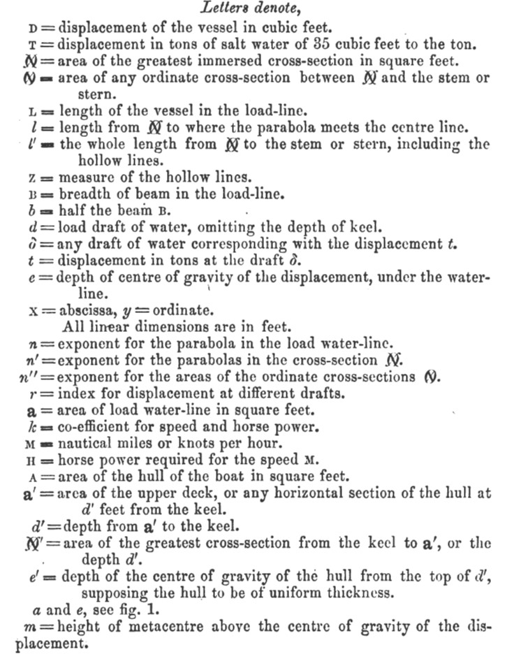
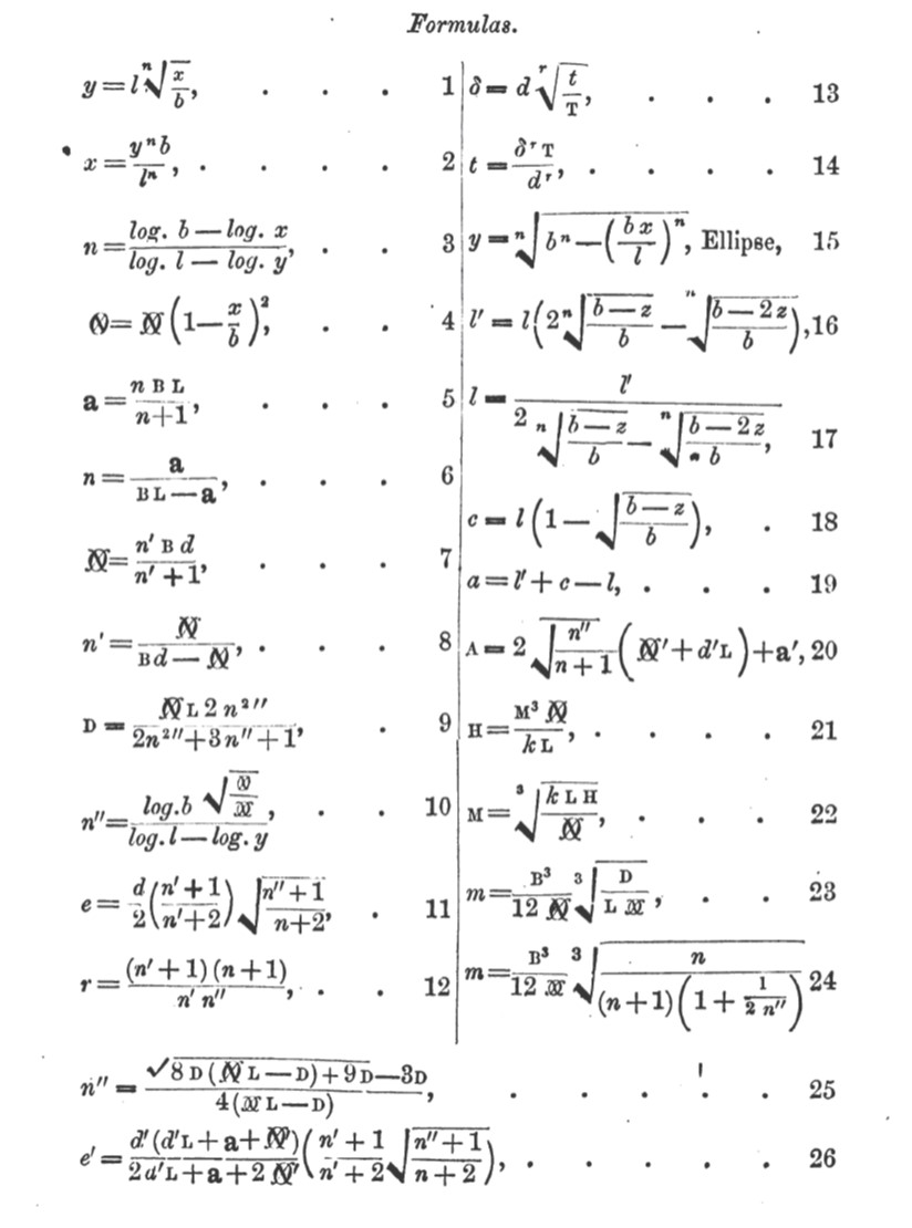
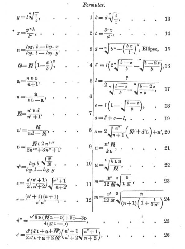
A brief jump forward – let’s visit the US in 1863, and an interesting little work by a gentleman by the name of John Nystrom. John W. Nystrom (Swedish: Johan Vilhelm Nyström) (1825–1885) was a Swedish born, American civil engineer, inventor and author. He served as an assistant Secretary and Chief Engineer of the United States Navy during the American Civil War. In 1863 he published an interesting little treatise (less well known than his writings on numerical systems and mechanics, apparently) entitled A Treatise on Parabolic Construction of Ships and Other Marine Engineering Subjects. Philadelphia : London: J.B. Lippincott & Co. ; Trèubner. http://catalog.hathitrust.org/Record/100209615. Let’s start at the beginning, when Nystrom introduces us to his theory. The Parabolic Construction of ships was originated by the celebrated Swedish Naval Architect, Chapman, who published a work on the same in the year 1775. Mr. Chapman came on the fortunate idea, that a vessel of the least possible resistance in water, should have the ordinate cross-sections of the displacement diminishing in a certain progression from the dead flat. In order to find out that certain progression, he collected a great number of drawings of ships of known good and bad performances; on each drawing he transferred the ordinate cross-sections to rectangles of the same breadth as the beam of the vessel, placed the upper edges in the plan of the water line, by which he found that the under edges of the rectangular sections formed a bottom, the curve of which was a parabola in the ships of the best known performances. I have labored very hard to find out some theory by which to sustain Chapman's hypothesis, but have not succeeded; found it necessary to start on new hypothesis, namely, that the resistance to a vessel of a given displacement, bounded in a given length, breadth and depth, is proportioned to the square of the sine of the mean angles of incident and reflection. By differentiating and integrating those angles, and finding their maxima and minima, will result in, that the square root of the ordinate cross-sections of the displacement should be ordinates in a Parabola, the principle upon which the Parabolic Construction is herein worked out. Whew! Sounds difficult. Nystrom then proceeds to offer 26 equations which define the fundamental properties of a ship based on parabolic design and construction.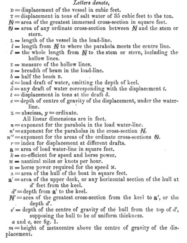
-
Seeking information on determining load waterline
trippwj replied to trippwj's topic in Nautical/Naval History
Well, it took me a bit, but I located the reference. Rev. Inman, in his 1820 translation of Chapman and added commentary (Chapman, Fredrik Henrik af. 1820. A Treatise on Ship-Building, With Explanations and Demonstrations Respecting Architectura Navalis Mercatoria Published in 1768. Translated by James Inman. Cambridge: Printed by J. Smith, sold by Deighton & sons. Page 277), offers the following: PREPARATION OF SOME OF THE PRINCIPAL LINES IN THE DRAUGHT. (10.) Before the constructor proceeds farther, it may be proper to draw the few lines he has fixed on in pencil, and to prepare the paper for the insertion of the other parts of ,the draught. Draw a straight line for the length of the load water-line from the after edge of the stern-post rabbet to the fore. side of the stem rabbet. At the extremities square up and down perpendiculars to this line; upon which take the draught of water head and stern, and draw a line for the bottom of the false keel. Set up square to this line the thickness of the false keel and next of the keel itself as far as the lower edge of the rabbet; and draw another line parallel to the former... Basing the development of the plan on the LWL rather than the previous standard of a "baseline" would open numerous areas for experimentation. While it may seem insignificant at first blush, the implications for the layout of the lines (such as the station lines being perpendicular to the waterline and NOT to the keel, as one example) certainly alter the paradigm. It is quite different from that described by Rees or Steel, as but 2 examples. Note, however, that toward the end of his description of designing a ship, Inman does add the following, on bringing the station lines back perpendicular to the keel (page 295): (41.) Lastly, it may be of considerable importance to form from the draught, now considered as complete, a block model of the vessel it is proposed to build; from which a still more accurate judgment may be formed of the fitness and beauty of the body. And should any defect be thus discovered, farther alterations must still be made; till the draught and the model are perfectly approved of. These different alterations and repeated calculations in some cases may appear very tedious, but they will not appear unnecessary to any person at all skilled in the business of construction. The many obvious reasons for using every means to ascertain the correctness and even nicety of every part of a ship, previous to its being built, need not be mentioned. The different transverse sections in the construction which follows, in conformity to the method described above" are projected on a transverse plane perpendicular to the load water-line; also the curves are supposed to be drawn on the outside of the planking. Whereas in draughts for building', the sections are perpendicular to the keel, and the curves go no farther than the exterior surface of the timbers. To form one draught from the other, to space the timbers, place the ports, &c. is a mechanical operation, which it would be improper to describe here; this is within the reach of every practical person tolerably acquainted with the use of the drawing pen. -
Wow, Buck. I haven't been around too much, so just catching up on your build. While she may be a tad picky, it appears that Becky has indeed sent you along a good path! Amazing looking work on the brass bits. Any idea what's next in the lineup?
- 515 replies
-
- 6
-
-
- artesania latina
- whaleboat
- (and 1 more)
-
Attached is the log of the Euryalus from Jackson, T. Sturges (Thomas Sturges). 1899. Logs of the Great Sea Fights, 1794-1805. Vol. 2. [London] Printed for the Navy records society. http://archive.org/details/logsofgreatseafi02jack. Pages from 1899 logsofgreatseafi02jack.pdf
-
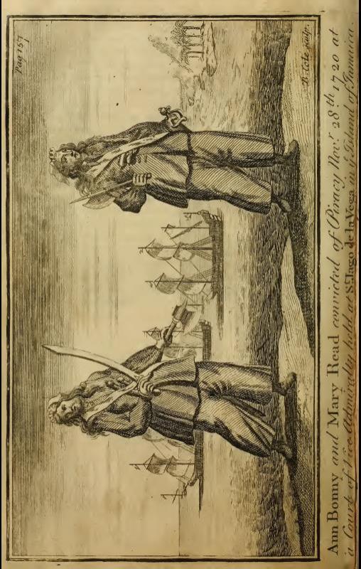
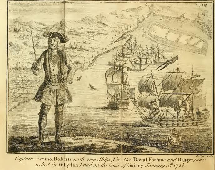
Uniforms of the Royal Navy and Marines circa 1724?
trippwj replied to timboat's topic in Nautical/Naval History
When in doubt, refer to either contemporary sources, which could be of mixed veracity:: Defoe, Daniel, and Charles Johnson. 1724. A General History of the Pyrates, : From Their First Rise and Settlement in the Island of Providence, to the Present Time. With the Remarkable Actions and Adventures of the Two Female Pyrates Mary Read and Anne Bonny ... To Which Is Added. A Short Abstract of the Statute and Civil Law, in Relation to Pyracy... London: : Printed for, and sold by T. Warner... http://archive.org/details/generalhistoryof00defo. Or Scholarly research: Little, Benerson. 2012. “Eyewitness Images of Buccaneers and Their Vessels.” The Mariner’s Mirror 98 (3): 312–26. doi:10.1080/00253359.2012.10709007.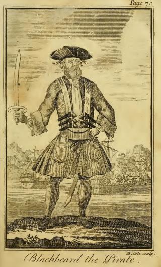
-
Maritime historian John Lyman wrote and edited a mimeographed news letter called Log Chips: A Periodical Publication of Recent Maritime History. Starting in July 1948, each issue was twelve pages and each volume consisted of 12 issues. There were four volumes between 1948 and 1959, and Norman Brouwer edited a series of Log Chips Supplements in 1980. From Issue 1: LOG CHIPS, of which this is the first issue, has been created to preserve and disseminate in a concise form the research of the Editor and his correspondents, and to serve as a means of communication among them. It is in no sense intended to be a competitor of “Sea Breezes”, "American Neptune", “Steamboat Bill”, or the other excellent periodicals already existing in the field of maritime history and nautical research. It is intended rather to supplement those publications by presenting, in an extremely simple format, lists and tabular matter of slight interest to the casual reader but of permanent value to the serious student, preliminary treatments of aspects of recent maritime history for circulation among those having personal knowledge of the facts and events; and observations and notes for which no suitable medium of publication at present exists. Each mimeographed issue offered a variety of information to the historian. Topics were wide ranging, and the collection is a wonderful resource for those people who are interested in commercial sail in the Pacific after about 1860. Most issues included a List of Launchings in the United Kingdom, biographical articles, launching lists for ship builders up and down the coast (such as Matthew Turner, Hans D. Bendixsen and the Hall Brothers). Lyman likewise covered the East Coast, particularly New England. The men and the companies who built the East Coast schooners were included, along with lists of schooners and their story from seven masts down to three masts. Why do I mention this, you might ask? Well, chummly, it seems that, through the generosity of the San Francisco Maritime National Historical Park, pretty much the entire collection of Log Chips has been posted to The Internet Archive. Note that these are NOT Google scans, but appear to have been done at a higher resolution specifically for the Archive. This is a treasure not to be missed! Here is a link to one issue – at the bottom of the page you will see more. https://archive.org/details/LogChips1948July Here is a bibliography of Lyman's various writings as well. lyman.pdf