trippwj
-
Posts
3,156 -
Joined
-
Last visited
Content Type
Profiles
Forums
Gallery
Events
Everything posted by trippwj
-
 Good point, Pat. As to a practice for securing shot in the racks, no info found as of yet, although ordnance has not been one of the areas I have spent very much time exploring (still have a research project on displacement to wrap up and submit for publication before I can look deeply into a different topic). Having said that, let me offer a couple of possible resources, always keeping in mind that the Endeavor was a unique vessel, and applying standard Royal Navy practice to her is probably an approximation at best, and misleading at worst. Such a unique mission, nonstandard vessel, and interesting crew makeup! The following are, in general, of a somewhat later period, although some of the practices were likely of a traditional type, and some historical information is also included in the treatise. Log books, scientific publications (such as Philosophical Transactions of the Royal Society of London or The Navy Chronicle) would be a potential source, along with the records from the Board of Ordnance. That is another interesting bureaucracy that had a strong influence on the Navy over a period of many years! Burney, C. 1867. The Boy’s Manual of Seamanship and Gunnery: Compiled for the Use of the Training Ships of the Royal Navy. 5th ed. Trübner & Company. https://books.google.com/books?id=1UcOAAAAQAAJ. Muller, John. 1768. A Treatise of Artillery ...: To Which Is Prefixed, an Introduction, with a Theory of Powder Applied to Fire-Arms. John Millan. Robins, Benjamin. 1805. New Principles of Gunnery: Containing the Determination of the Force of Gun-Powder, and an Investigation of the Difference in the Resisting Power of the Air to Swift and Slow Motions. With Several Other Tracts on the Improvement of Practical Gunnery. F. Wingrave. Sir Howard Douglas. 1855. A Treatise on Naval Gunnery. J. Murray. http://archive.org/details/bub_gb_PK50sbOOfjUC.
 -
While NOT specific to the Endeavor, here are a couple of excerpts from Simmons, R. 1812. The Sea-Gunner’s Vade-Mecum: Being a New Introduction to Practical Gunnery, Expressly Accommodated to the Use of the Royal Navy, &c. and Including the Rules of Decimal Arithmetic, So Much of Practical Geometry as May Be Required in the Art ... and a Variety of Information with Instructions Useful to Gunners, Both at Sea and On-Shore. Steel and Company. Starting on Page 62: Regarding the gunner's duties: 8. He is never to keep any quantity of powder in any other part of the ship than the magazine, except that which the captain shall order to be kept in the powder-boxes, or powder-horns, on deck ; 14. He is to be attentive in keeping the shot-racks full of shot, the powder-horns and boxes of priming-tubs full, and a sufficient quantity of match primed and ready for being lighted at the shortest notice. 27. Whenever he shall be directed to strike any guns into the hold, he is to pay them all over with a thick coat of warm tar and tallow mixed together ; and, after having washed the bore of the gun with fresh water, and very carefully spunged and dried the inside, he is to put a good full wad, dipped in the same mixture, about afoot within the muzzle, and to see that the tompion is well driven in and surrounded with putty ; and he is to drive a cork tight into the touch-hole, and to secure it there. Note particularly item 27 - the crew would certainly not be very pleased hauling these buggers from the hold as a major cleaning would be required. Likewise, striking them back to the hold! Both are very messy work, not to mention back breaking (remember, a "4 pound gun" weighs in at something north of 11 cwt, so even these wee beasties were no simple thing to move around below decks, particularly as the carriage was also stowed below and not affixed to said barrel for moving it around). In terms of the Endeavor, I would suspect a minimum of shot stored on deck - no reason for the added weight on the upper works if the guns were in the hold, so why have that extra weight on the deck (reduces stability somewhat by raising CG). Likewise, since bringing the guns up from the hold was not something done in an hour or so (remember, they needed to be cleaned of all that protective stuff before use), there was likewise plenty of time to bring shot (as well as powder, for that matter) up and prepare it before the guns were ready for action.
-
Cruizer-class Brig-Sloops of the Royal Navy
trippwj replied to molasses's topic in Nautical/Naval History
That makes sense - Fincham was a major part of the School f Naval Architecture with Inman. His success may, perhaps, be best described by the death notice in The Times (1859): The death of this gentleman [John Fincham] took place at his residence at Highland Lodge, near Portsmouth, yesterday morning, in his 75th year. The deceased gentleman will be best remembered by the general public as for many years master shipwright of Portsmouth Dockyard, and more especially as the builder of the celebrated Arrogant, the first screw frigate possessed by this country, and still looked on as one of the finest of her class. Much of his time and study was devoted to the introduction of the screw propeller into the British navy. For a long period he was superintendent of the School of Naval Architecture at Portsmouth. His History of Naval Architecture, Outlines of Shipbuilding, a Treatise on Laying-off Ships, and on Masting Ships, are unequalled in the English language for the amount of research and professional knowledge they contain. His 1843 work was at the tail end of Symonds tenure as Surveyor of the Navy, and reflects one of the 3 major views in that prolonged period of discord (Symonds' "empirical" school of shipbuilding came into conflict both with the "scientific" school led by the new class of professional naval architects and the first School of Naval Architecture (such as Fincham, Morgan, Creuze, Pearse &c.), and the "traditional" school led by Master Shipwrights from the Royal Dockyards. Quite an interesting period of time for the British Navy that period from about 1790 through 1850. -
Cruizer-class Brig-Sloops of the Royal Navy
trippwj replied to molasses's topic in Nautical/Naval History
Concerning point 2 - the Crown OWNED the Oak growing in Britain. HOWEVER - quality Oak, in the quantities needed, was becoming more scarce. See, among other research, the following: Albion, R.G. 1926. Forests and Sea Power: The Timber Problem of the Royal Navy, 1652-1862. Harvard University Press. http://archive.org/details/ForestsAndSeaPower. Knight, R. 1986. New England Forest and British Seapower: Albion Revisited. The American Neptune XLVI, no. 4: 221–229. Layman, W. 1813. Precursor to an Exposé on Forest Trees and Timber ... as Connected with the Maritime Strength ... of the United Kingdom. https://books.google.com/books?id=KNxbAAAAQAAJ. Loewen, B. 2000. Forestry Practices and Hull Design, Ca. 1400-1700. In Fernando Oliveira E O Seu Tempo. Humanismo E Arte de Navegar No Renascimento Europeu (1450-1650), ed. F.C. Domingues, 143–151. Patrimonia. https://www.academia.edu/5766940/Forestry_practices_and_hull_design_ca._1400-1700. An additional consideration, particularly at this time, is that the theory and science of Naval Architecture was undergoing a sometime vicious shift in the paradigm of design. This was the period of the Reverend Inman and George Atwood. We also saw the influence of the Society for the Improvement of Naval Architecture and Fredrik Henrik Chapman on the field. The changes, while sometimes slow, were incremental and evident. They were not accomplished via simple edicts from the Surveyor of the Navy and Admiralty (history showed how poorly that approach had worked over many decades - too many of the ship yards were passive-aggressive on implementing those orders). Steel, as a case study, perhaps, is in a unique category. There has been, since long before our life time, speculation concerning the source for his Naval Architecture. The timing of the publication implies that there was some connection to the attempt to incorporate scientific theory into ship design - and, indeed, some of the narrative in Steel's Vade Mecum seem to advocate for such a path. Steel was a publisher and former barrister with the Admiralty, but not a ship builder nor rigger. What he was, however, was well connected - as evidence by his ship lists &.c. published over many years. -
Cruizer-class Brig-Sloops of the Royal Navy
trippwj replied to molasses's topic in Nautical/Naval History
Would be quite interested in your source for this table - based solely on the terminology used, this appears to be a late 19th century analysis rather than a contemporary description. Also, given the long history of the class, as well as the number constructed, there was quite probably a difference between the early rig dimensions and the latter members of the class. -
Welcome aboard! You may find some useful information in these books: Lubbock, B. 1975. The Colonial Clippers. Brown, Son & Ferguson. ———. 1984. The China Clippers. The Century Seafarers. London: Century Publ. MacGregor, D.R. 1993. British & American Clippers: A Comparison of Their Design, Construction and Performance in the 1850s. Annapolis, Md: Naval Institute Press. MacGregor, D.R., and G. Hunt. 1984. The Tea Clippers: Their History and Development 1833 - 1875. 2. ed., and expanded. London: Conway Maritime Press [u.a.].
- 4 replies
-
- 2
-

-
- Tea Clippers
- British
- (and 4 more)
-
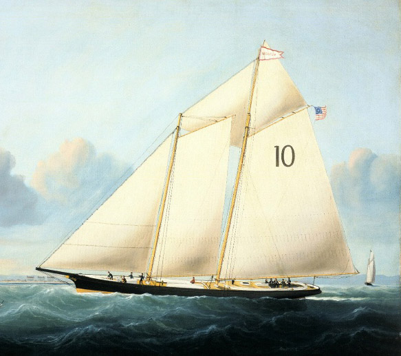
Continues to come along nicely, Elijah. As to the strange cockpit, I suspect it served 2 purposes - (1) provided a spot to sit while manning the helm or passing time. They carried multiple pilots (as many as 6 or 8) when on station, and the pilots were not essential to operating the vessel itself (there was a separate crew of 4 sailors, a cook and a the boatkeeper, an apprentice pilot, responsible for operating the vessel when none of the pilots remained on board). (2) provided a measure of protection from any water that came over the deck to prevent it getting into the cabin. These were fairly small vessels, comparatively, and often provided pilot services in rough conditions, beating into a sea to disembark the pilot onto the ship they were meeting. Indeed, they frequently ranged far off shore, competing with other pilot boats to reach an incoming ship first. In addition, as pointed out by Chuck in his practicum, the deck within the cockpit would be about a foot lower than the surrounding deck - the cockpit coaming also provided a measure of trip and fall protection for the crew working the deck. There is some good description of these boats in Leather, J. 2002. The Gaff Rig Handbook: History, Design, Techniques, Developments. 2nd ed. Brooklin, ME: Woodenboat Publications. See http://blueworldwebmuseum.org/item.php?id=283&catid=78&category=Schooners&artist_id=60for the original of this painting.
- 701 replies
-
- 9
-
-
- phantom
- model shipways
- (and 1 more)
-
While not specific to the vessels shown in this thread (which are absolutely amazing), there is some fairly detailed description of the lateen rigged Mediterranean vessels (including some very good lines drawings and frame disposition from wrecks) in Castro, F., N. Fonseca, T. Vacas, and F. Ciciliot. 2008. A Quantitative Look at Mediterranean Lateen- and Square-Rigged Ships (Part 1). International Journal of Nautical Archaeology 37, no. 2: 347–359. http://onlinelibrary.wiley.com/doi/10.1111/j.1095-9270.2008.00183.x/abstract. Information for model making (at least for some of these types) may, perhaps, be available from http://www.grazianogozzo.com/en/barche.htm
-
Seeking information on determining load waterline
trippwj replied to trippwj's topic in Nautical/Naval History
I wanted to take a moment to consider the manuscript attributed to Baker. From Castro, F. 2002. Fragments of Ancient English Shipwrightry. Ship Treatises and Books. http://nautarch.tamu.edu/shiplab/treatisefiles/ttfragments.htm The Fragments of Ancient English Shipwrightry is a collection of miscellaneous notes and incomplete plans of ships started by an English shipwright named Matthew Baker (1530-1613) in the 1570s, and continued with notes from one of his apprentices, John Wells, and annotations on mathematics. Baker was born in 1530, the son of a shipwright of King Henry VIII of England. There is notice of him traveling to the Levant in January 1551, at the age of 21, probably as a ship's carpenter aboard an English merchantman. He may have visited Italian and Greek shipyards and collected Venetian and Greek designs of midship frames. A fairly cultured man with a good understanding of mathematics, he certainly had contacts and was influenced by the Italian shipwrights hired by Henry VIII in 1543. These Italians appear to have remained in the country for over forty years, earning wages thirty percent higher than their English counterparts. In 1572 Baker was appointed Master Shipwright of the kingdom. He worked with other men of knowledge, and his notes reflect the first steps of a trend to change English shipbuilding from the medieval empirical method to the modern standard of paper plans and conceptual models that could be repeated, improved and enlarged. When he died in 1613, he left the manuscript to his neighbor and protégé John Wells. Baker's notes present a compilation of precious observations, abacus, tables, and drawings, comprising more than 30 geometrically defined midship sections, from the sections of 4 galleasses designed by his father, James Baker, in the second half of the 16th century to the early 17th century midship sections that were in use when new methods to determine the rising and narrowing of the bottom of the vessels in the central portion were fully defined in England. The part added by John Wells is mostly occupied with calculations of spherical geometry, making extensive use of logarithms from 1617 on. Richard Barker (1985 - “Fragments from the Pepysian Library.” Revista Da Universidade de Coimbra XXXII: 161–78.) provides additional information concerning this manuscript. Of particular interest for this post is the following: One of the more intriguing aspects of the numerical work in Fragments is the frequent calculation of sectional areas of moulds below the depth by Baker, usually linked with the product breadth x depth, effectively giving a prismatic coefficient. Taken with Bourne’s Treasure for Travellers on mensuration of ships lines and waterplanes, from which it is perfectly clear that Bourne and his contemporaries knew how to measure displacement tonnage at any selected draught, either as a paper exercise or with the use of models, it is difficult to avoid the conclusion that Deane’s contribution to the principles at least of determining displacement (and thence draught at launching) has been overstated. It appears to rest entirely on Pepys’ record of what Deane told him. Even Deane is not explicit in his Doctrine about his methods in the procedures covered now by Simpson’s Rules, and begs a number of question in his treatment. Just what Baker was doing with prismatic coefficients and immersed (?) areas of sections remains a mystery, but the practice should at least be credited to his era. It is at least possible that the incentive for both Baker and Wells was the search for a satisfactory tonnage rule. Baker apparently changed his method about 1582: Wells was heavily involved in a Commission to investigate tonnage rules in 1626. Johnston, S. 1994. Making Mathematical Practice: Gentlemen, Practitioners and Artisans in Elizabethan England. PhD Dissertation, University of Cambridge. http://www.mhs.ox.ac.uk/staff/saj/thesis/ A re-creation of the figure from Page 35 pf Fragments: The diagram is a simplified version of Baker’s drawing. There are many more inked and scribed lines in the original, as well as numbers for the calculation of areas. In this example of Baker’s procedures for drawing the midship mould, breadth and depth are given as 36ft and 16ft respectively. dg = 1/5 ed. With eh = dg, draw gh. Then draw ec, cutting gh at i. Through i draw mk perpendicular to ed; ek is the floor for this half of the mould. Mark point l on gh such that hl = 2/3 gh. The first centre n is on mk and has its arc passing through k and l. Extend line ln beyond n; the second centre o is found on this extended line and its arc sweeps from l to c. To find the third centre, first mark the other half of the floor with p. The third centre q is at the intersection of oc and pn (extended). Baker then draws the upper futtock in three different ways. Bellamy, Martin. 2006. “David Balfour and Early Modern Danish Ship Design.” The Mariner’s Mirror 92 (1): 5–22. doi:10.1080/00253359.2006.10656978. Page 12: With Balfour’s contract for the Hummeren in 1623 there came another significant change in that the contract specified the draught of the completed ship. This was a notoriously difficult measurement to predict and along with a vessel’s tonnage, was surrounded by a certain element of mystery and mystique.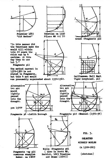

-
Very nice work, Maurys. Glad to see you have gotten those stern timbers under control.
- 525 replies
-
- 1
-
-
- anchor hoy
- hoy
- (and 1 more)
-
Tools and techniques used in the 18th Century
trippwj replied to tkay11's topic in Modeling tools and Workshop Equipment
MM is "Mariners Mirror", published by the Society for Nautical Research. Their website is snr.org.uk and you can search the MM archives from their (first published about 1911 as I recall). -
Tools and techniques used in the 18th Century
trippwj replied to tkay11's topic in Modeling tools and Workshop Equipment
Tony - You may also want to take a look at some of the writings and research by R.C. Anderson, Nance and others (see various volumes of MM during the 1920's) concerning ships models. Very interesting descriptions and analysis offered. Keeping in mind the evolution of purpose for the "Admiralty" style models, there was quite likely a parallel evolution in the craftsmanship and the nature of the tradesman doing the modelling (the earliest were used to 'sell" a design to the decision makers, while the later were a part of the materials required to be submitted, along with plans and drawings, for consideration.) The tools used quite certainly also changed over time. Considering that folks like Hahn and Underhill were able to produce amazing models, of similar character to the "Admiralty" style, using mostly simple hand tools (many home made), I would suspect that 200 years earlier, the tradesman making the model was not working with very much else. Indeed, considering that model making was not a frequent requirement, I doubt if there was a position in a government yard (commercial yards more probably to have someone) who had a primary job of building models. More likely a task assigned to apprentice ship wrights learning the trade in the loft and drafting sections. -
What are these? does anybody knows? thanks.....
trippwj replied to BIGMAC's topic in Masting, rigging and sails
The descriptions of how these rigs were operated would tend to support a designed curvature. The optimum location for the sail is on the leeward side of the mast so that it is pushed away from the mast, filling and using the most available sail volume. In order to accomplish this, the yard would need to be brought to the other side of the mast. One (probably most common) way this was done was to bring it to a nearly vertical position then physically wrestle the yard to the other side of the mast. The curved yard would ease this by keeping the ends away from the mast, avoiding (or at least reducing) interference with the mast itself as well as shrouds. See Campbell, I.C. 1995. The Lateen Sail in World History. Journal of World History 6, no. 1: 1–23. http://www.jstor.org/stable/20078617as well as Castro, F., N. Fonseca, T. Vacas, and F. Ciciliot. 2008. A Quantitative Look at Mediterranean Lateen- and Square-Rigged Ships (Part 1). International Journal of Nautical Archaeology 37, no. 2: 347–359. http://onlinelibrary.wiley.com/doi/10.1111/j.1095-9270.2008.00183.x/abstract (available at http://nautarch.tamu.edu/shiplab/00-pdf/Castro%202008%20-%20IJNA%20-%20Lateeners%201.pdf ) -
What are these? does anybody knows? thanks.....
trippwj replied to BIGMAC's topic in Masting, rigging and sails
I have continued digging as time allows, but surprisingly little detail accessible (that is the operative word) concerning the actual manufacture of the spar. I can find a huge volume concerning the evolution and dispersal of the rig, and some tantalizing tidbits that I can not access (see, for example, Landström, B. 1961. The Ship: An Illustrated History for what is purported to be a good description of how the lateen sails were handled). I would suspect, based solely on the visual evidence of the attachments (on galliots, galleys &c.), that they were indeed sometimes of other than sheep skin. Rounded wooden "caps" would offer nearly similar protection (the purpose being to protect the aft sail from damage). -
Sorry to hear about the recent misfortune, Sjors. Having seen your work, however, I have every confidence that you shall persevere and rebuild it even nicer! Looks great so far, though. All the best -
-
What are these? does anybody knows? thanks.....
trippwj replied to BIGMAC's topic in Masting, rigging and sails
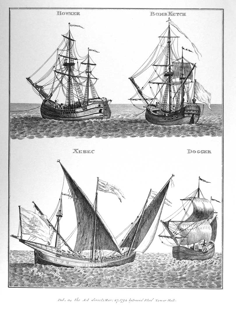
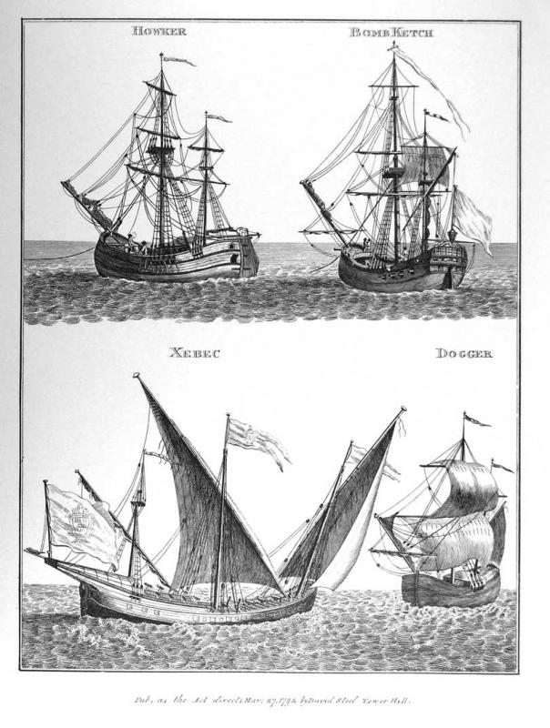
Not really getting much closer concerning the function, however the object in question is hardly unique to the galleot. Note the 2 images below where Steel shows a similar appendage on the Xebec and the Pink. Decidedly not a sheave (block, pulley &c.). No lines evident in any of the views, yet control lines are visible along the lateen yard. May want to take a look through some of the history of fore and aft rig resources out there (Chatterton, Leather, R.C. Anderson) for descriptive information.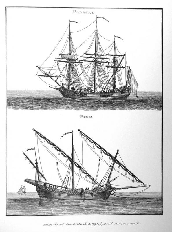
-
Cruizer-class Brig-Sloops of the Royal Navy
trippwj replied to molasses's topic in Nautical/Naval History
You may want to consider downloading in PDF a slightly abridged version of Steel (note that the plates are missing from this, however they can be pulled from the link provided above). STEEL, D. 1806. The Art of Rigging ... The Second Edition, Considerably Enlarged and Improved; with Additional Tables, Expressly Adapted for Merchant-Shipping. https://books.google.com/books?id=Cq1WAAAAcAAJ. Biddlecombe also has a good resource (some claim it is a reprint of Steel, others that Steel and Biddlecombe used the same original sources. Note that Steel was a publisher, not a mariner. Biddlecombe was a mariner). Biddlecombe is also available for either download or as a Dover reprint. Biddlecombe, G. 1848. The Art of Rigging. http://books.google.com/books?id=9RkEAAAAQAAJ. Last one to look at would be Darcy Lever. Lever, D. 1819. The Young Sea Officer’s Sheet Anchor, Or, A Key to the Leading of Rigging, and to Practical Seamanship. Dover ed. Mineola, NY: Dover Publications. -
Thanks, Greg - I do need to save up for both of these!
-
Now, if he is only interested in the subject of ship models, as opposed to ship modelling, and also not a fan of the coffee table (that is, mainly photos) book, there are not a lot of options out there. For just one book, I would recommend R. Morton Nance, 2000. Classic Sailing-Ship Models in Photographs. Dover ed. Mineola, N.Y: Dover Publications. This modern reproduction by Dover books is from the 1924 original by Nance, R.M. Sailingship Models, a Selection from European and American Collections. Halton and T. Smith. The 2000 reprint is available for under $1 USD on Amazon (not including shipping), or for the Kindle (and other ereaders) for $9.99 USD via Dover (or Google or Amazon &c.) Other possibilities include some of the research articles in journals such as Mariner's Mirror. See, for example, Laughton, L.G.C. 1925. The Study of Ship Models. The Mariner’s Mirror 11, no. 1: 4–28. http://dx.doi.org/10.1080/00253359.1925.10655300. Unfortunately, in the same manner as there not being one exemplary "how to" book that meets every beginners needs, there is not a signle all encompassing book concerning the history and development of ship models. The book by Nance and the collections listed in the Laughton article are, perhaps, the most comprehensive discussions of which I am aware.
-
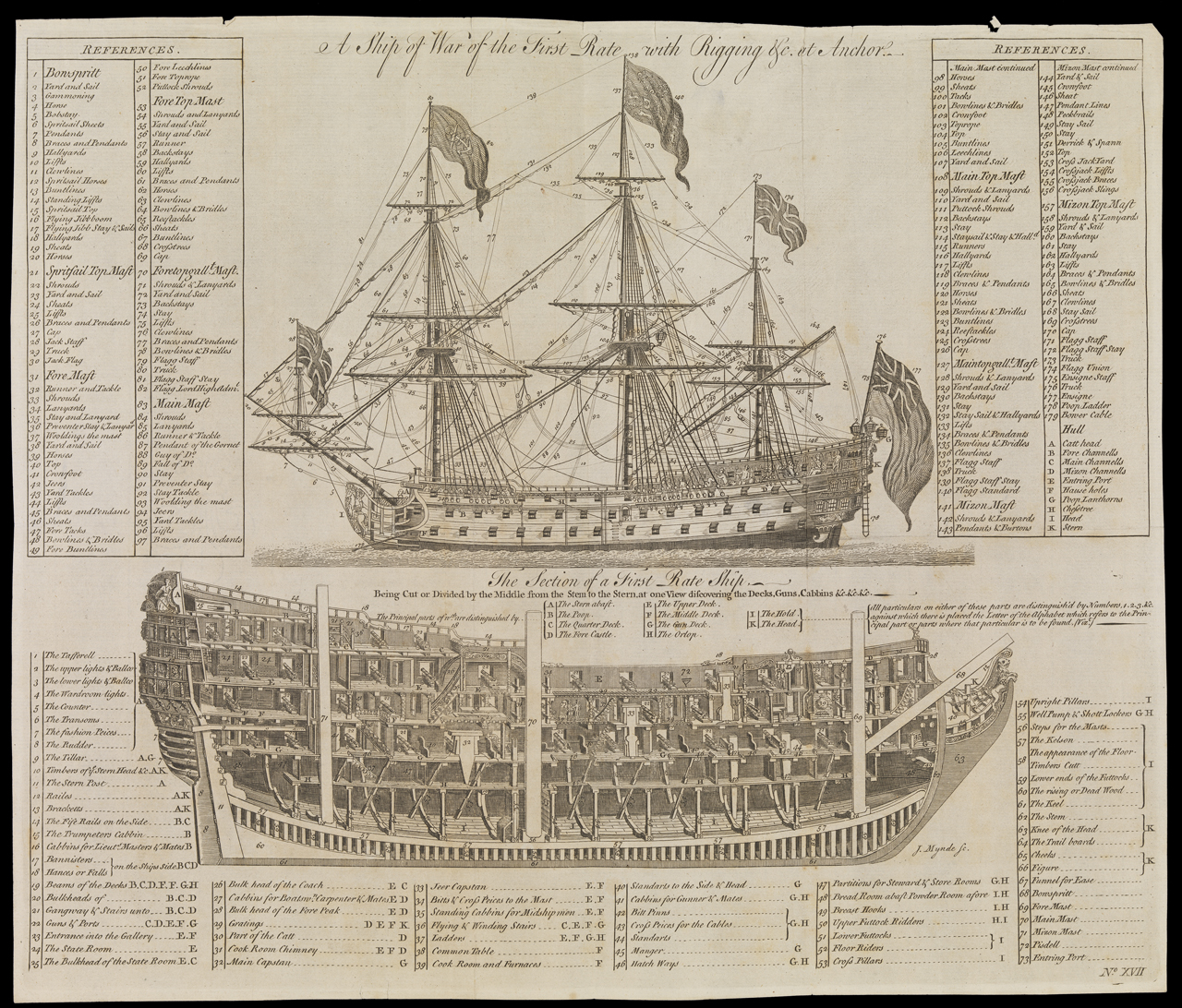
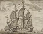
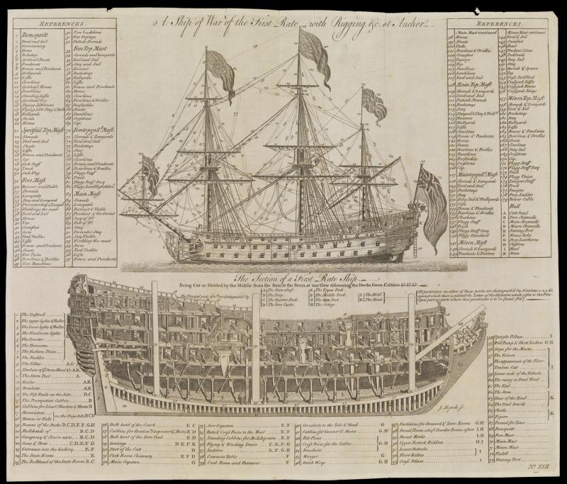
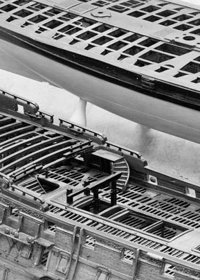
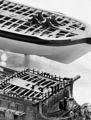
Daniel - Here are a couple of relatively contemporary items for your consideration. Note the model of the Britannia appears to show the same scuttles. Looking through Longridge and Campbell, I was surprised to not see any indication of the scuttle either in the text nor on the plans by Campbell. NMM. 1719. Britannia (1719); Warship; First Rate; 100 Guns - National Maritime Museum. Model, Ship, Wood. National Maritime Museum, Greenwich, London. On loan from the Worshipful Company of Shipwrights. http://collections.rmg.co.uk/collections/objects/66184.html. Note the small opening to the port side of the ladder to the lower deck. Not so evident at the foremast, however. This may offer a glimpse at the run of the lines. J. Mynde 1754?. A Ship of War, of the First Rate, With Rigging &c at Anchor. The Section of a First Rate Ship - National Maritime Museum. Engraving. http://collections.rmg.co.uk/collections/objects/152570.html.
-
For the solid hull Phantom, about 0.5" at most. Measure the length of the supplied lower mast dowel. Then, from the plans, measure the height of the lower mast above the deck. The difference (dowel length minus height above deck) is the amount available for your hole in the solid hull. Start slightly short of the target and dry fit to see if things look right.
- 701 replies
-
- 6
-
-
- phantom
- model shipways
- (and 1 more)
-
Any particular time frame and nation? English and American rigging practice began to diverge drastically during the early days of the US Navy. There is information in the Humphreys Notebook for several American Naval vessels. The British navy is much more thoroughly covered, as you no doubt have discovered. There are also some Dutch, Spanish and french resources, although I am not as familiar with them. Anderson is a very good resource - his perspective was a bit broader than just Britain, and he covered earlier time periods. Best of luck!
-
You may want to contact Model Expo and explain the problem - they may replace the hull for you.
-
Explanation of Dockyard Terms circa 1691
trippwj replied to trippwj's topic in Nautical/Naval History
Sorry about that - link should work now. For nearly 700 photographs and sketches from the excavation, see https://canmore.org.uk/search/image?SIMPLE_KEYWORD=dartmouth&per_page=96&images_page=1 -
Explanation of Dockyard Terms circa 1691
trippwj replied to trippwj's topic in Nautical/Naval History
The Dartmouth is an interesting vessel - and does represent an example of taking a "rebuild" to an extreme! A very detailed report on the archeological survey and supporting research may be found in Martin, C.J.M. 1978. The Dartmouth, a British Frigate Wrecked off Mull, 1690 5. The Ship. International Journal of Nautical Archaeology 7, no. 1 (February 1): 29–58. A downloadable version may be found here: http://orapweb.rcahms.gov.uk/wp/00/WP000741.pdf There is included a precis concerning various repairs, which notes that during a "Refit at Captain Castle’s Dock, Rotherhithe, 6 June 1678", among other repairs was an expense of 132 £ 15 s 0 d for "Fitting a new maine keele 88 ft 6 in x 13 in square" There is a rather extensive listing of the additional repairs made at that time included. Interesting, just a year later (1679) there is an expense at Portsmouth for 408 £ 17 s 9 d for the following: 2 gundeck beames on each side of the maine mast to be shifted ‘being rotten and ready to fall in hold’. Several knees of the same deck to be shifted, and new bolts to be drove in the rest. Two pairs of standards to be fitted to the lower deck. Three lower deck beames-one broken and two decayed to be replaced. Some lower deck knees to be shifted, A string to be brought on under the gun deck ports. Part of the upper deck to be shifted. Quarter deck crossbeames to be replaced. Breast hooks to be new bolted. New cathead timbers. New tillar. Part of the maine wale to be shifted. Several gundeck ports to be new. Gun wales, railes, and planck sheirs to be repaired. Joiner, carver, painter and glazier work required. To be caulked withinboard and without, and to be graved per estimate