trippwj
-
Posts
3,156 -
Joined
-
Last visited
Content Type
Profiles
Forums
Gallery
Events
Everything posted by trippwj
-
 Very nice work, Tony. Love those little details for the interior!
- 129 replies
-
- 4
-

-
- armed launch
- panart
- (and 1 more)
-
Seeking information on determining load waterline
trippwj replied to trippwj's topic in Nautical/Naval History
Thanks, Dave! Interesting side bar: Lord Barham set up a Commission of Revision which reported in 1806, among other things, that there should be a deeper study of the principles of ship design. It was recommended that the best apprentices in the Royal Dockyards should be given special instruction in Naval Architecture and related subjects. The first School of Naval Architecture was set up in Portsmouth in 1811 but, following a change of Government, was abolished in 1832. Inman and Fincham were among the faculty. Indeed, at that same time Robert Seppings was replaced as Surveyor of the Navy by William Symonds. Seppings, you may recall, published two significant treatises on ship building - On the Great Strength Given to Ships of War by the Application of Diagonal Braces and On a New Principle of Constructing Ships in the Mercantile Navy. Quite the uproar over appointing a non-shipbuilder but rather a Naval officer (and purely political patronage appointment) to the position of surveyor of the navy! -
Seeking information on determining load waterline
trippwj replied to trippwj's topic in Nautical/Naval History
Several times during our discussion the point has been made that design waterlines were just that – the desired draught for a fully loaded ship. Indeed, that was the intent, but it was also a critical design element. By the 18th century, a warship was designed with a desired number and weight of guns on a specified number of decks. This primary design criterion brought with it a host of other specifications – the intended crew size and composition (as well as the accommodations for officers &c.), the weight in powder and shot for the typical mission profile, the quantity of spares and materials for repairs, the victualling and water, and on and on. It also, based on the weight of gun, drove the scantlings to support the guns and facilitate their use. While the weight of all of these could be estimated (see earlier posts), they were far from firm – there was always variability. The ship designer needed to consider these factors, along with the form of the vessel for best sailing and handling, to ensure that when fully loaded the vessel maintained a safe freeboard (well defined by the 1700’s as 3 to 5 feet from LWL to lowest gun port). I suspect that it was the increased focus on the builder delivering a ship which achieved an appropriate compromise between these various factors (handling, speed, draught of water and ability to carry intended weapons and supplies) which ultimately forced the shipbuilder to actually determine the displacement and determine whether the ship design could achieve what was desired. While there was a certain amount that could be done to mitigate the draught by adding or removing ballast, this had implications for the handling and seaworthiness of a ship – the ballast was intentionally there to bring the center of gravity (even if not understood as such) lower and improve the roll and pitch – to keep her from becoming crank, as it were. Too little ballast resulted in a top heavy ship that rolled excessively. The same holds true for merchant ships – the ballast was much more variable (and there are many documented cases where ballast was added or removed for specific cargos), but the builder (and owner) wanted to maximize the cargo capacity for a given set of tunnage admeasurement rules, while ensuring adequate speed, handling and (of some great importance for some routes) keeping the overall draught of water within a given limit (particularly for bays or harbors with shallow entries or bars). At the same time, the merchant wanted to use a small a crew as possible, so the types and nature of the rigging was also a major consideration. How did they balance all of these, in the absence of slide rules, spreadsheets and calculators -
Seeking information on determining load waterline
trippwj replied to trippwj's topic in Nautical/Naval History
Bruce - You bring up some excellent points! For constructors, the emphasis on cargo tunnage as the measure of the ship (even for warships) meant that they had little reason to think in terms of displacement tons when measuring their ships. This fact partly explains the long delay in many countries in adopting displacement tonnage as a unit of measure, as both constructors and owners (including admiralties) continued to apply the simpler admeasurement rules and avoided the more exact measures required for correctly calculating displacement. There is evidence that some British constructors were estimating load waterlines by the 1630s, although it was probably not common practice. For example, see the examples in this post http://modelshipworld.com/index.php/topic/9892-seeking-information-on-determining-load-waterline/?p=296187 And this one http://modelshipworld.com/index.php/topic/9892-seeking-information-on-determining-load-waterline/?p=300218 Ferreiro, among others, makes the point that displacement calculation as a matter of routine was unique, perhaps, in that usually the need to accomplish something drives the development of a methodology. In the case of displacement, and the subsequent stability calculations, the need to calculate the curves and so on was driven by the development of the capability – which, to a certain degree, was driven by the financial interest in accurate determination of cargo capacity. Much of the theory related to displacement was driven as well by interest in determining the best forms for a ship to “divide the water”. A great deal of effort was expended in model basin testing to try and derive the best shape – and some interesting detours into false premise and failed designs followed, as well as some successes. We know that there were successful efforts to identify the swimming and LWL as far back as the 1600’s. We have the plan for the Danish ship Elephanten (1705) built and designed by Olaus Judichær showing clearly marked waterlines (see facsimile in Ferreiro, Ships and Science). We have the contracts and information by the Pett’s, and also by Deane. We have the LWL beginning to routinely show on plans by the mid-1700’s in British ships. By the late 1700’s we have Humphreys and other American designers discussing the design draught for their ships. What we also have, though, is a clear indication that while it was possible, it was not routinely done. In 1791, we find the establishment of The Society for the Improvement of Naval Architecture in Great Britain. Among their early awards, was the following: The Societv offer a Premium of Twenty Guineas and the Silver Medal for the most ready and accurate method, by approximation or Otherwise, for determining the tonnage of vessels and ships of every description, from an admeasurement of all the principal dimensions. Among the contributions was one by Chapman discussing the Swedish methodology. It is an interesting and worthwhile read. Society for the improvement of naval architecture London. 1792. Some Account of the Institution, Plan, and Present State, of the Society for the Improvement of Naval Architecture: With the Premiums Offered by the Society, List of Members, and the Rules and Orders of the Society. To Which Are Annexed Some Papers on Subjects of Naval Architecture Received by the Committee. http://archive.org/details/someaccountinst00unkngoog. We also have, slightly later, Steel (1805) bemoaning the fact that displacement is not calculated: By this rule, all vessels, whether their bodies be extremely full or. extremely sharp, will appear to be precisely of the same burthen or capacity, if the length of keel and extreme breadth be similar. Thus, the sharpest cutter will seem to carry as much as the fullest merchant-ship of the same length and breadth extreme. This method is, of course, exceedingly detrimental to that principle which promises velocity; as the ship which is narrowest above, and widest and deepest below, will measure least in proportion to her real capacity; the very reverse of which is necessary for fast sailing. In order to ascertain the true burthen of a ship, we ought to find the place of the light-water line, and thence calculate the number of cubic feet below the line of floatation: as the product, deducted from the number of cubic feet contained at the load-draught, would shew the real capacity by which the tonnage may be computed: and, if the difference be multiplied by the weight of a cubic foot of sea water, 64 3/8 lbs., the product, divided by 2240 (the number of lbs. in a ton), will give the true burthen in tons. Or, in other words, by deducting the weight of the ship at her light-water mark from her weight when brought down to the load-water mark, the remainder will be the tonnage. -
Seeking information on determining load waterline
trippwj replied to trippwj's topic in Nautical/Naval History
By all means, feel free to print it off and peruse at your leisure! I keep going back to that Humphreys calculation and pondering why the tunnage is so great. Here is a direct paste from his 1793 letter to Samuel Hodgdon: Dec 16, 1793 Dear Sir I think it necessary to inform you in what manner the tonnage is calculated that I have made the estimate from. In the first place to find the length of straight rabbet forward you take 3/5 of the beam as usual from that point to the after part of the stern post allowing its width for measurement not to exceed 1/12 of the beam. That length being determined you then multiply it by the length of beam & that product by the height of the gundeck beam amidship on the top of the beam added to half of her waste amids which last product divide by 95 which will give the number of ton required. I am respectfully yours &c Joshua Humphreys It is that additional factor (1/2 her waste amidship) that results in the dramatic increase in tunnage. I pulled up another description from him dated 1804 (in response to an inquiry from the auditor of the navy concerning builders measure in Philadelphia in 1799). In this letter, he does NOT include that addition to the depth of hold! 'Dear Sir I shall with pleasure endeavour to explain the Mode of ascertaining the Tonnage you require I hope it will be satisfactory. The rule for ascertaining of Tonage of Vessels Carpenters Measure in this Port in the Years 1799 & 18oo was as follows- Breadth of Beam was ascertained from the outside to outside of the timbers - or the Moulded Breadth at dead flat or widest part of the Ship or from inside to inside of the plank or Wales at the same place, which is the same thing. When the length of Beam is so found you take three fifths of its length which is allowed for the rake of the Stem, let the rake be what it may either more or less - but the rake is generally less- In order to assertain the point of straight rabbet on the Keel, you must set 12 inches before the rabbet of the Stem at the height of the Gundeck from that point let fall a line at right Angles with the rabbet of the Keel then Measure from that line 3/5 of the Beam & wherever that distance terminates on the Keel is the point called straight rabbet & from which to the rabbet of the stern post is the length of Keel for Tonage Carpenters measure of this Port - then Multiply the length of the Keel so found by the Breadth of the Beam as above & that product by half the length of the Beam- which last product divide by ninety five which will give the Number of Tons required. (transcription provided in M. V. Brewington. 1941. Notes: Tonnage Rules in 1799. The American Neptune: A Quarterly Journal of Maritime History and Arts I, no. 3: 295–296. http://phillipslibrarycollections.pem.org/cdm/compoundobject/collection/p15928coll3/id/939). When I change the depth of hold to 1/2 the beam, the calculated tunnage is much more agreeable - 1080 & 68/95 tuns carpenters measure. Mr. Humphreys was an interesting character, and regrettably his working notebook (compilation of all sorts of tidbits around shipbuilding &c.), while containing a great deal of information, is NOT chronological, in the sense that it traces events in order, but rather a sequential listing of information in the order it was entered. For example, the first entry is a transcription of the British 1719 Establishment, followed by a description of some method of ascertaining tunnage (NOT either of the two above given), then followed by more of the 1719 Establishment. This is then followed by an entry titled "Navy Office, August 1st 1737 Dimensions", and about 20 pages later "An abstract of numbers, natures, lengths & weight of cannon according to several rates of ships as proposed at a meeting of Flag Office and established by His Majestic Council on the 6th of July, 1716." -
Seeking information on determining load waterline
trippwj replied to trippwj's topic in Nautical/Naval History
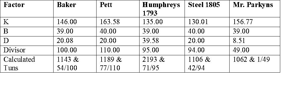
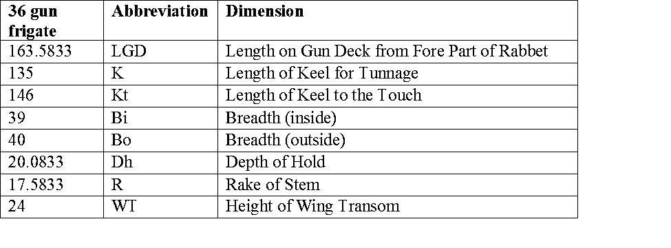
The next step in the process, then, is to look at how these various measures compare when looking at a single vessel. I opted, for convenience sake, to work with the design specifications for the 36 gun frigates from Joshua Humphreys, primarily because I had a good detailed set of specifications available. Note that the actual vessels “as built” differed from these specifications, but for my purposes here that was not important. The calculations here are preliminary – I still have some additional tweaking to do, but they serve to illustrate how broad the tunnage can be when the different admeasurement methods are used. K = length of Keel for tunnage B = Beam (maximum breadth) D = Depth of Hold for tunnage

-
Seeking information on determining load waterline
trippwj replied to trippwj's topic in Nautical/Naval History
There are several dozen potential ways that have been identified by Salisbury (among others) for measuring tunnage. For the sake of simplicity and illustration, I am only going to highlight a few of them. Mr. Bakers Old Rule (from about 1582): The old way, which was established in Queen Elizabeth's time, and never questioned all King James time, is this: The length of the keel, leaving out the false post, if there be any. Multiply by the greatest breatdh within the plank, and that product by the depth taken from the breadth to the upper edge of the keel produceth a solid number which divided by 100 gives the contents in tons, into which add one third part for tonnage, so have you the tons and tonnage. K = Length of keel excluding false post B = greatest breadth within plank D = depth from B to upper edge of keel Divisor = 100 Naval Papers of Peter Pett (about 1650) Take the Length from the inside on the Upper Deck between the Stem and the Sternpost, and the greatest Breadth from Outside to Outside: likewise, the Depth from the underpart of the Beam of the Upper Deck to the floor by the side of the Keelson. Multiply the Length by the Breadth, and that by the half Breadth, except the Depth exceed the half Breadth, then you are to multiply by that and divide the quotient by 110. K = Inside on upper deck between stem and stern post B = greatest breadth outside to outside D = depth from underpart of beam to floor by side of the keelson or ½ B, whichever is greater Divisor = 110 The Massachusetts Rates and Duties Act. (In The Acts and Resolves of the Massachusetts Bay (Boston, 1869-1922), I, pp. 207-8.) (from about 1695) ... the breadth at the main beam within board, the depth to be accounted half the said breadth, and the length three times so much as the breadth, after the usual manner of multiplying, and dividing the product by one hundred. K = 3 x B B = width at main beam within board D = ½ B Divisor = 100 An Act for Making a Convenient Dock or Basin at Liverpool (1709) Take the length of the keel of every ship or vessel so much as she treads on the ground and the breadth to be taken within board by the midship beam from plank to plank and half that breadth shall be accounted for the depth ... Then the tonnage will be (L x B x D)/94… any custom practice or usage notwithstanding. K = Length of keel treads on ground B = width at midship beam within board D = ½ B Divisor = 94 13 Geo. III, c. 74 (pg 1) (The Smuggling Act.) The' Old Rule', adopted for general use in all later Acts until the 'New Measurement' of 1836. (1772) The length shall be taken on a straight line along the rabbit of the keel of the ship, from the back of the main-post to a perpendicular line from the fore part of the main-stem under the bowsprit; from which subtracting three fifths of the breadth, the remainder must be esteemed the just length of the keel to find the tonnage; and the breadth shall be taken from the outside of the outside plank, in the broadest place in the ship, be it either above or below the main wales, exclusive of all manner of doubling-planks that may be wrought upon the sides of the ship; then, multiplying the length of the keel by the breadth so taken, and that product by half the breadth, and dividing the whole by ninety four, the quotient will be deemed the true contents of the tonnage. According to which rule the tonnage of all such ships and vessels shall be measured and ascertained, anything in the said recited act of the sixth of George I, or any other act or acts of parliament, to the contrary notwithstanding. K = Along rabbet of keel from back of main post to perpendicular from forepart of main stem below bowsprit, minus 3/5 B B = greatest breadth outside to outside exclusive of doublings D = ½ B Divisor = 94 U.S. Stat. L, vol. I, p. 55. United States Tonnage Law, passed 1st September 1789. Known as 'Custom House Measurement'. (1789) The length was measured from the fore part of the main stem, to the after part of the sternpost, above the upper deck. From this, 3/5 of the beam was deducted in order to obtain the Length for Tonnage. The breadth was measured at the broadest part above the main wales. The depth varied. In single decked vessels the depth was measured from the underside of the deck plank to the ceiling in the hold. In ships with two or more decks, the depth was taken to be half the breadth. K = the fore part of the main stem, to the after part of the sternpost, above the upper deck minus 3/5 B B = the broadest part above the main wales D = Single decked: underside of deck plank to ceiling in hold. Double decked = ½ B Divisor = 95 Joshua Humphreys, War Department Papers TNB06 (1793) http://wardepartmentpapers.org/document.php?id=9527 In the first place to find the length of straight rabbet forward you take 3/5 of the beam as usual from that point to the after part of the stern post allowing its width for measurement not to exceed 1/12 of the beam. That length being determined you then multiply it by the length of beam & that product by the height of the gundeck beam amidship on the top of the beam added to half of her waste amids which last product divide by 95 which will give the number of ton required. K = length of straight rabbet forward minus 3/5 B to after side stern post B = width at midship beam within board D = top of gun deck beam to floor plus ½ B Divisor = 95 The following are provided in Steel’s Vade Mecum (1805) THE GENERAL RULES OBSERVED FOR MEASURING THE TONNAGE OF SHIPS IN THE KING'S AND MERCHANTS’ SERVICE, ARE AS FOLLOW. Let fall a perpendicular from the foreside of the stem, at the height of the hawse-holes*, and another perpendicular from the back of the main post, at the height of the wing transom. From the length between these perpendiculars, deduct three-fifths of the extreme breadth+, and likewise as many 21/2 inches as the wing transom is high from the upper edge of the keel, and the remainder is accounted the length of the keel for tonnage. Then multiply the length of the keel for tonnage by the extreme breadth, and that product by half the extreme breadth; then, dividing by 94, the quotient will be the burthen in what is denominated Builder's Tonnage. Or, Multiply the length of the keel for tonnage by the square of the extreme breadth, and divide the product by 188, the quotient will be the burthen in tons. K = length from foreside stem at hawse holes to back of main post at wing transom minus 3/5 B minus 2 ½ “ per height of wing transom above upper edge of keel. B = extreme breadth outside to outside D = ½ B Divisor = 94 * In the merchant-service, this perpendicular is let fall from the foreside of the stem, at the height of the wing transom, by reason of the hawse-holes being generally so very high, and their stems also having a great rake forward. + By the extreme breadth, is meant the breadth taken from timber to timber outside, with the thickness of the bottom on each side added; or, which is the same thing, the thickness of the bottom on each side added to the moulded breadth. RULES BY MR. PARKYNS, LATE OF HIS MAJESTY's YARD, CHATHAM. RULE I. For Sharp Ships, particularly those of the Royal Navy, Take the length on the gun-deck, from the rabbet of the stem to the rabbet of the stern-post, or between the perpendiculars. Then take 23/24 of this length, and call if the keel for tonnage: To the extreme breadth add the length of the gun-deck, or length between the perpendiculars; then take 1/23 of this sum, and call it the depth for tonnage, Set up this depth from the limber strake; and, at that height, take a breadth also from out to outside of the plank at dead-flat, and another breadth between that and the limber strake; add together the extreme breadth and these two breadths; take one-third of the sum, and call it the breadth for tonnage. Multiply the length for tonnage by the depth for tonnage, and the product by the breadth for tonnage, and divide by 49. The quotient will be the burthen in tons nearly. K = Length on gun deck (between perpendiculars) x 23/24 B = at height D above limber strake take breadth outside to outside. Add to extreme breadth plus breadth at limber strake divide the sum by 3. D = extreme breadth plus LBP x 1/23 Divisor = 49 Rule II. For Ships of Burthen, or Commercial Ships, in general, Take the length of the lower deck, from the rabbet of the stem to the rabbet of the stem-post; then take 31/32 of this length, and call it the keel for tonnage. To the extreme breadth add the length of the lower deck; then take 3/55 of the sum, and call it the depth for tonnage. Set up this depth from the limber strake; and, at that height, take a breadth also from out to outside of the plank at dead-flat. Take another at two-thirds of this height, and another at one-third of the height. Add the extreme breadth and these three breadths together, and take one fourth of the sum for the breadth for tonnage. Multiply the length for tonnage by the depth for tonnage and the product by the breadth for tonnage, and divide by 36.6666 or 36 2/3 and the quotient will be the burthen in tons. K = Length on lower deck (between perpendiculars or LBP) x 31/32 B = at height D above limber strake take breadth outside to outside at dead flat. Take second at 2/3 this height and a third at ½ the height. Add to extreme breadth plus these three breadths and divide the sum by 4. D = extreme breadth plus LBP x 3/55 Divisor = 36 2/3 (36.6666) -
Seeking information on determining load waterline
trippwj replied to trippwj's topic in Nautical/Naval History
Well, I’m back. I have taken a brief detour into the realm of tunnage admeasurement, not simply for my personal education, but because it is so closely intertwined with the development of accurate determination of displacement for a vessel. I won’t bore you with a history of tunnage admeasurement – that is very well covered in numerous other more detailed studies (See attached bibliography) Tunnage References.pdf Saulisbury (1966a) offers the following very concise description of admeasurement: Some sort of tonnage measurement, based on some arbitrary and artificial unit of capacity or weight, was necessarily closely connected with the development of merchant shipping. Warships could be described satisfactorily by the number of men or guns carried or by the number of oars or men required to propel them, and even today some small craft can be classed by such 'natural' units. Ships designed to carry cargo, however and particularly those driven by sails-needed altogether different treatment. In default of statutory enactments, an artificial unit which was to be generally acceptable had to evolve by usage alone, and this demanded a state of economic activity in which large quantities of a common commodity were frequently shipped over a wide area. Many of the references (see attachment) address the inaccuracy of the methodology used – essentially, the maximum breadth was a key factor, the length of keel for tunnage was a derived measurement (that is, it was not a measurable length but rather derived from other values, of which more below), and the depth of hold was, likewise, generally derived from the breadth. The result was that two vessels having the same breadth and length (whether on gun deck or between perpendiculars) would have the same tunnage, with no account of the shape of the ship. A sharp vessel with large deadrise would have the same tunnage as one with a flatter bottom and full body. While this was good for the collection of customs duties, it was not equitable across vessels nor a true reflection of cargo capacity. For a model builder, some important considerations arise – The Length of Keel provided in many references works (such as Winfield) are not always able to be identified as actual length of keel or length of keel for tunnage – two very different values! Period documents are not always clear as to which methodology is used to determine the tunnage, and in many cases (as we shall soon see) the value is not able to be recreated based on available data. Methods for determining the tunnage changed many times over the more than 300 years of interest, varying not only by nation but also by region. Some terminology may be of use before I look at a few of the methods used to admeasure tunnage. Admeasurement: The measurement of cargo capacity, usually in volume (tuns) Ton/tonnage: The term "ton" can describe both weight and volume, so to avoid confusion, ton and tonnage will be used for weights and displacements. Tun/tunnage: These terms will be used for volumetric measures (admeasurement). -
Taking this solid hull to a whole new level - very thorough and detail oriented - which are good things!!! Carry on!
- 701 replies
-
- 2
-
-
- phantom
- model shipways
- (and 1 more)
-
What lays first?
trippwj replied to Telp's topic in Building, Framing, Planking and plating a ships hull and deck
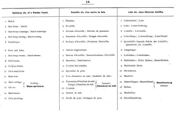
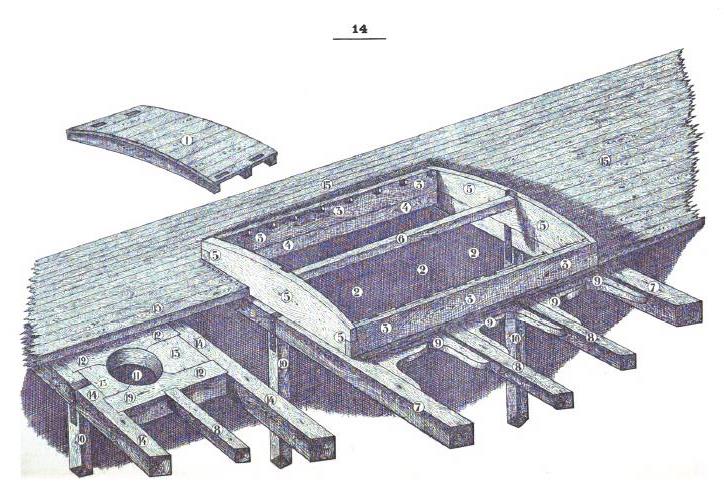
This is from Paasch, H. 1901. “From Keel to Truck” Marine Dictionary in English, French & German... https://books.google.com/books?id=mG_VAAAAMAAJ&.
-
What lays first?
trippwj replied to Telp's topic in Building, Framing, Planking and plating a ships hull and deck
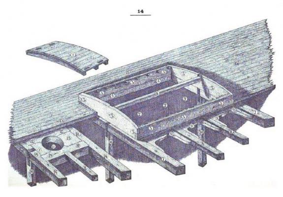
Not necessarily the best, but here is one example of framing around a hatch. (Source: Curtis, W. H. 1919. The Elements of Wood Ship Construction. http://archive.org/details/TheElementsOfWoodShipConstruction ) I will keep checking some other resources to see if I can find a better sketch. Any particular ship/era/type you are interested in? Practice varied, as in so many parts of ship building, over time and between nations.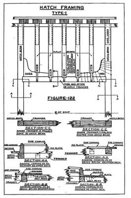
-
What lays first?
trippwj replied to Telp's topic in Building, Framing, Planking and plating a ships hull and deck
In a real ship, the deck planking ends at the hatch coaming (often thicker right around the hatch). -
Next up, a very incomplete listing of model ship building related books. I only have about a third of these - Please feel free to offer up additional titles to add to the list! Model Shipbuilding Resources 20Mar2016.pdf
-
Table of Contents Laying the Keel (Gene Bodnar) Behind the Tiller - an interview with Ed Tosti One Eyed Willy’s Treasure Hunt (Sponsored by Lauck Street Shipyard) The Model Shipwrights Lumberyard (Dave Stevens) Silver Soldering (Bob Hunt) On the Cover - Ocean Harvester Turning Belaying Pins (Bill Edgin) Modelers Toolchest - Magnification Shipwrecks of the World - USCG Escanaba Heraldic Ship Badges - HMCS Ville de Quebec The Book Nook - Nicolaes Witsen and Shipbuilding in the Dutch Golden Age Gene’s Nautical Trivia http://www.msbjournal.com/
-
Looking good, sir. You may want to look for the book by Gene Johnson on building ship models - he has a short section on shaping solid hulls.
- 701 replies
-
- 2
-
-
- phantom
- model shipways
- (and 1 more)
-
Bummer, dude - but if you aren't satisfied, then a re-do is the way to go! I thought things were already looking good, so can only imagine the next result!
- 1,616 replies
-
- 6
-
-
- caldercraft
- agamemnon
- (and 1 more)
-
Continuing with Topical selections, here is an Assortment of Resources on the Original American Frigates. First Frigates Resources 13Mar2016.pdf
-
Thought I would add a brief listing of resources on Dutch shipbuilding. Far from comprehensive, but a start. Dutch Resources 13Mar2016.pdf Additional suggestions welcome - enjoy!!!
-
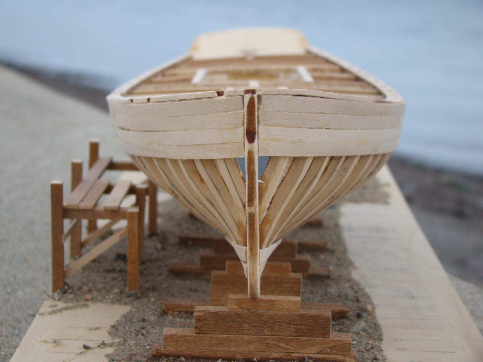
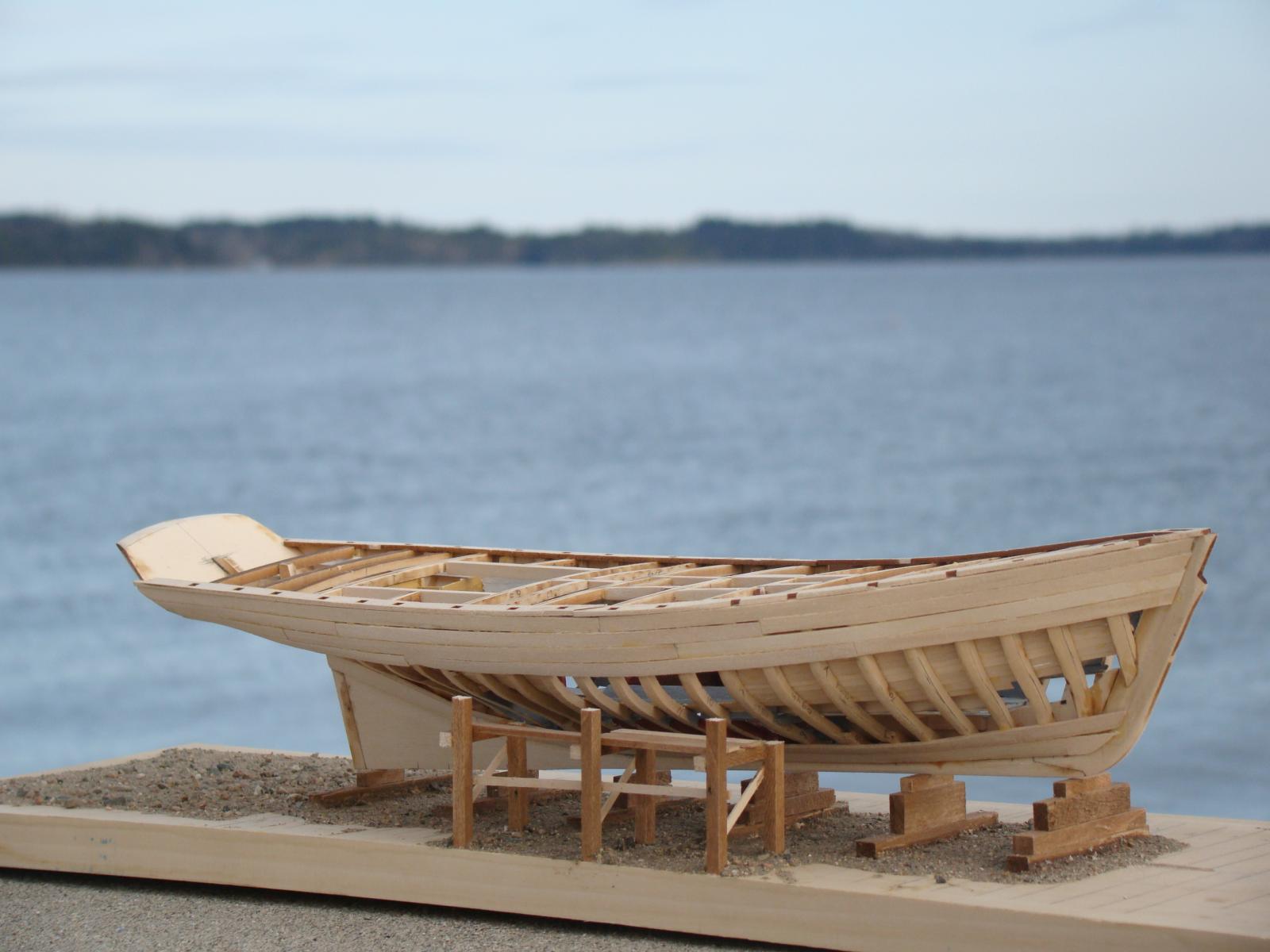
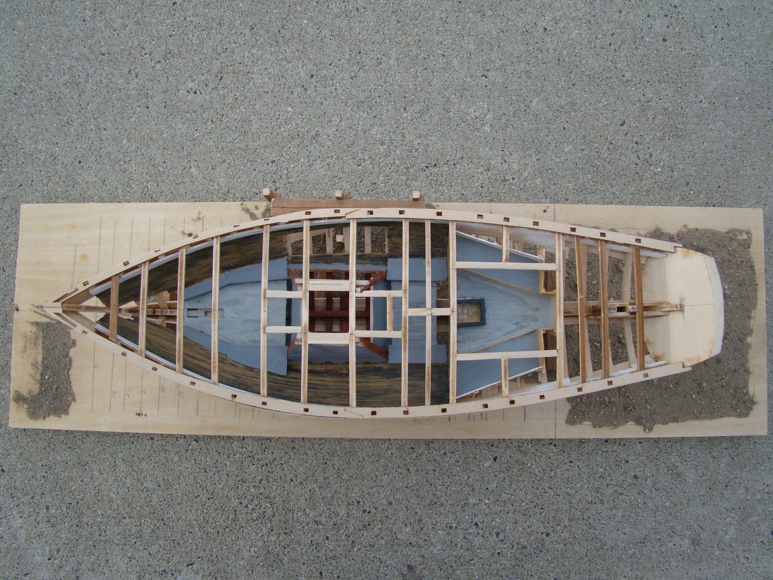
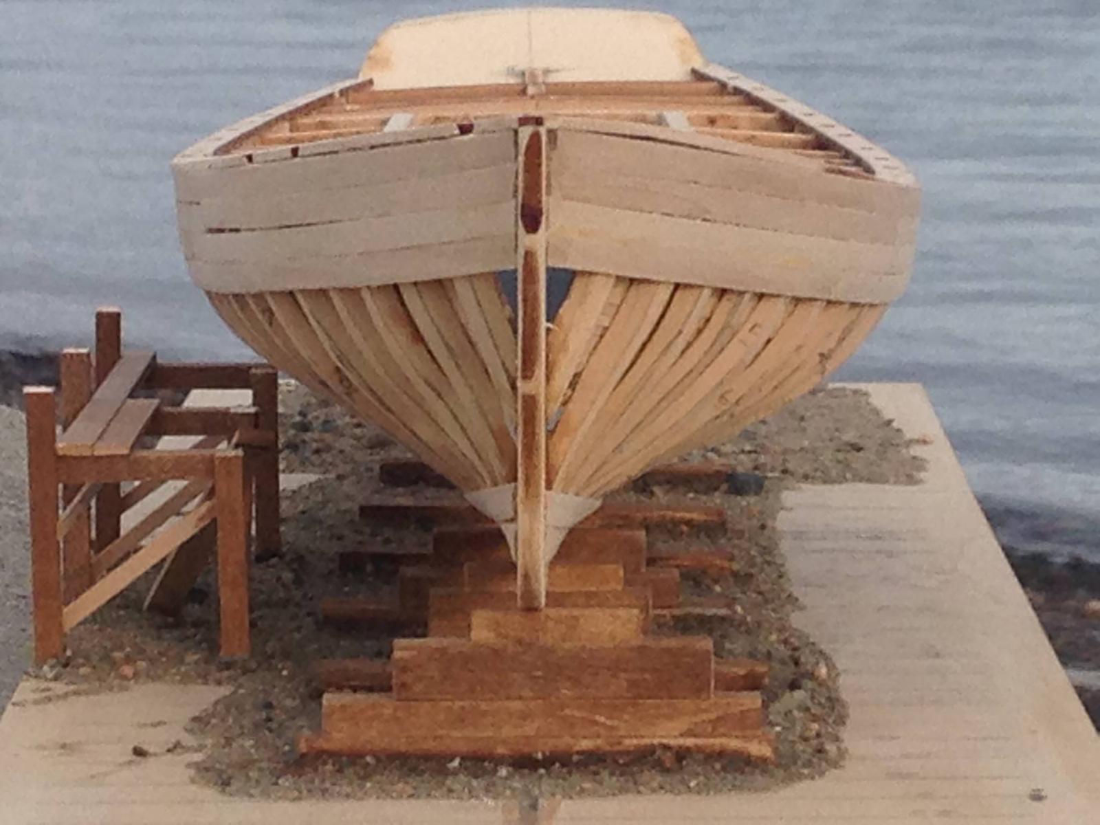
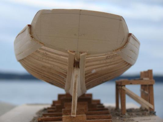
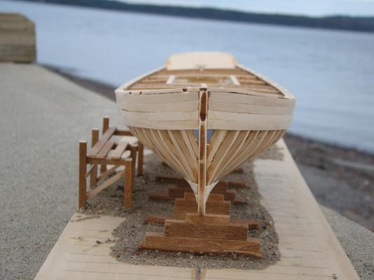
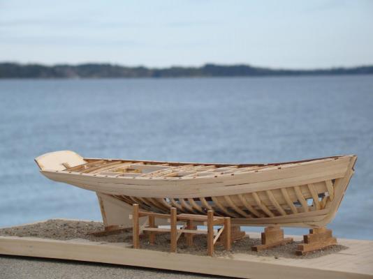
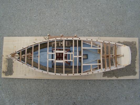
Well, now, I guess it's time for some updating! The workshop is now re-floored and operating. The ECB is on the table and have added the garboard strake and the next strake above. Moving along very slowly, but progress is occurring! Since the weather was so nice, I took her down to the shore for some pictures in her "natural habitat". Starboard side - this is the side that will be partly planked (the port side will be fully planked). Bow view Stern view View from above.


-
The subsciption frigate New York and other details
trippwj replied to CharlieZardoz's topic in Nautical/Naval History
Should one have an abiding interest in the papers of Samuel Humphreys, one would be well served to inquire of the Historical Society of Pennsylvania concerning the availability for public research in the following collection - Joshua Humphreys papers (Collection 0306), The Historical Society of Pennsylvania. Listed amongst the collection, should one be so inclined to investigate, are found the following entries - Volumes 1739-1845 2.0 Linear feet ; 19 volumes Volume 18: Samuel Humphreys Philadelphia Naval Yard journal (1818 - 1820) Volume 19: Samuel Humphreys surveys of ships (1834 - 1845) Also - Box 3, Folder 8: Samuel Humphreys documents (1806 - 1838) Box 3, Folder 11: Loose documents from Volumes 18 and 19 (1818 - 1845)- 51 replies
-
- 5
-
-
- frigate
- subscription
- (and 1 more)
-
What they all said, Denis! Looking spiffy, she is. I like the lighting effect - nicely done!
-
Gracious! Step out for a week or so and miss a total revision to the concept! Looks nice, Denis. As noted by others, the whole world is watching and waiting anxiously to see what becomes of the that temptingly open and flat surface.......
-
She is progressing well, my friend. Your gnomes are doing admirable work on those animal parts!
- 1,616 replies
-
- 5
-
-
- caldercraft
- agamemnon
- (and 1 more)
-
Looking good there, Tony. I'm probably not the best to ask about planking - haven't finished planking a hull yet (3 started, with 1 suspended and 2 delayed due to life). It think you've gotten the basics on the planking down quite well!
- 129 replies
-
- 5
-
-
- armed launch
- panart
- (and 1 more)
-
When considering Continental (American) practice, keep in mind the variety of influences upon their approach to shipbuilding. British, Dutch, and French design practices all influenced, in varying degrees, the American shipwright. many (perhaps most?) were not exposed directly to British (naval) practices until they were already well established as shipbuilders. Remember, until the late 18th century, there were NO dedicated warship constructors in America - all were builders of commercial ships that dabbled (on occasion) in privateers and small ships of war. Humphreys, as one example, was not a builder of warships (though it is generally accepted that during the Revolutionary War there were a couple built in his yard). He was, however, likely intimately familiar with the French Designed/Dutch built Frigate South Carolina (L'Indien). The reported scantlings of the South Carolina are very similar to those of a British 74 gun ship - and are commonly believed to have strongly influenced Humphreys design of the original 6 American frigates.