

baskerbosse
-
Posts
212 -
Joined
-
Last visited
Content Type
Profiles
Forums
Gallery
Events
Everything posted by baskerbosse
-
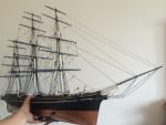
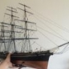 Definitely the right choice adding the sails! Looks great! Is the mizzen yard going up a bit more? Fore end looks a bit close to the deck? Room for the sail to clear the deck? (with bonnet?) Cool idea with the bottom of the display case as a weather deck (though you do know that the Vasa did not have treenailed weatherdeck?) Looks nearly finished, and a great looking model! cheers, Peter
 -
Thanks! That’s a good picture. I was looking for one where the main halliard could be seen, but have not been able to yet. Another omission on the 1/10 model? Oh dear.. For those intersted in scandinavian rigging around this time, church ships can be a source of information, as long as one is careful. A lot of these have been subjected to multiple ‘renovations’ during their life, but rare ones have original rig or professionally restored: https://commons.m.wikimedia.org/wiki/Category:Models_of_ships_in_churches_in_Sweden# Especially the one in Dalarö church is quite interesting. It has been renovated, but was found in need of renovation but with original rig by Sam Svensson who was heavily involved in the early Vasa efforts. Prior to his work on the Vasa, Sam had spent some 30 years on researching these. One of the aspects of rigging he investigated was the mast head, which he argued, based on these church ships (at least the ones with sufficently preserved rigging) the recovered masts of the Vasa, a mast recovered from the ship ‘Gröne Jägaren’, has a common theme of evolution back to the Viking masts (There is an article ‘A Seventeeth Century Masthead’ by him in Mariners Mirror 48, 1962), specifically concerning how the mast head takes the load of the shrouds, but also the sheaves integrated in the mast practice. But you are not rigging your Viking ship? ;-) Cheers, Peter
-
Very nice and clean. Looks much more like Clayton’s setup now. Yes, there would be a lot of penned up research findings regarding the rigging. I fully expect the Vasa II book to be filled with both ‘aha’, and additional uncertainties and confusion. Research has a tendency in general to go from ‘dead sure but wrong’ to ‘full of caveats but increasingly correct’. For example, from memory, I believe Fred once pointed out that it would be warranted not to raise a mouse on the stays. It had been found that it was apparently not always done in the days, sometimes it was just a loop and there is no evidence either way... So there, an example of more information leading to less certainty. :-) We had some interesting discussions covering many aspects of the rigging in the previous forum I mentioned, but there is bound to be even more not yet revealed information, so I keep waiting for the book! ;-) One detail I noticed and pointed out to Fred (not many things you can point out to Fred!) was that the Vasa rigging was supplied by a scotsman. There is also a contemporary rigged bone model of the Danish ship ‘Norske Løve’ in Rosenborgs Castle which was also rigged by a scotsman. It shares many rigging similarities with the Vasa. For example the famous ‘mystery’ combination of ‘dutch’ caps and sheaves in the masts.. You might want to have a look. There's an article on this forum: https://modelshipworld.com/index.php?/topic/11869-ivory-ship-model-rosenborg-castle-denmark/ Nearly done now! And looking excellent! Cheers, Peter
-
Hi Marc, Especially if you are interested in the ship as an archeological find, Vasa I is for you. Very interesting chapters on the deterioration process on the sea floor, the recovery of the ship and it's many finds. It also has in separate sheets new drawings of the hull, decks and cross section (5 plans) plus a colour 3D bottom survey map of the sea floor in the area of the wreck site. For those who may be interested in the older discussions 2006-2013, they mostly took place here: https://groups.yahoo.com/neo/groups/SwedishWarshipWasa/conversations/messages In regards to the proportions of the stays, the numbers for their diameter given by Fred back then were: Forestay: 115 mm Mainstay: 135 mm Mizzenstay: 85 mm , possibly even 75 mm The stay diameters were apparently derived from the strop scoring in the stay deadeyes, so should be fairly accurate. Also, Michael, it pains me to say this, but you're bound to find out once you get Vasa II anyway; -None of the ropes were served on the Vasa, save for the clews on the sails, research has found. The serving of the ropes on the 1/10 model date back from the 80s and is based on known practices from 18 century treatises and has unfortunately been found to be inaccurate. It does make for very neat looking ropes though. Cheers, Peter
-
Hi Michael, There are many aspects of the Vasa that have conflicting evidence with no clear cut solution. I have had the privilege of participating in many discussions with Clayton, Fred (and further back Lars Bruzelius) in regards to the Vasa and its technical details. I too have the Corel kit, but have become somewhat bogged down in the build and am currently building WWI aircraft models instead. :-/ Partly the mounting number of needed corrections, partly the ongoing wait for Vasa II. I am very impressed with what you have accomplished with your model. The Corel kit is quite a bit of a challenge here. Sorry if my comments are causing more work in the finishing up phase. (In your place, I would probably leave it as is at this late stage of the build. At most pop the blocks out and only replace those. If there is still not enough room behind the mast.) Regardless of what you do, it's still an excellent model. Viking ship next? Cheers, Peter
-
Hi Michael, In my opinion, the main trick here is to create something to scale that looks reasonable. As you noted, the Corel deck cutout is quite a bit too large. In reality, the opening is about the same diameter as the mast, and as can be seen it is centred directly behind the mast. I believe Clayton had to exaggerate the offset of the stay somewhat, due to scale issues with blocks and ropes. On Clayton's model, the stay appears nearly tangential to the mast, whereas on the real ship it does not appear to be more than to the side of the central mast timber. It seems that with the Corel model, the problem gets even greater due to the smaller scale. (Which may be why they made the deck opening larger) The Corel mizzen stay blocks end up being a size close to the diameter of the main mast, which is clearly overkill for a mizzen stay of the size of the Vasa's. I think Fred has mentioned earlier that the 1/10 does not represent the most recent findings, but I would still think that exceeding the correctness of the 1/10 would be quite an accomplishment! (The 1/10 model provides no solution to this problem and is just rigged with the ropes clashing. ) Cheers, Peter
-
Hi Michael, Looking excellent as usual! I really like how the sails and the rigging is turning out. With regards to the main halliard, I think you’ll find that it is indeed centered behind the mast. It is the mizzen stay that is offset to port. Usually hard to see on photos because of the angle required for a good picture does not seem to line up with visitor viewing points.. :-/ Here’s the best I could find: https://i.pinimg.com/originals/05/03/6c/05036c72fbbbe3af86e39dda5a8e0b2d.jpg Here’s a picture of Clayton Johnson’s excellent model: https://5881f258-a-62cb3a1a-s-sites.googlegroups.com/site/clayton707/swedishwarshipwasa/5.JPG?attachauth=ANoY7cq867DXhshM1gm1J-ta4ePpFgwa4p_KPc9UG45CYqGSQotA8LvT5q09GC4kb64l7gPdNVB8_HwC5Ft6zXIwvskG7AAlCUtJXmOV_qEtOH3msNBkYLRcaYuIPPQFVJgtAEhiYHOzlNeN6TMBsYawwP6e7HB3qpZOckJrZkVwTZz5Dynx1qka86aOeOF9bhXBrdpOsbs65b9SWpgofvr46SCPNZw3SC0mWBpwKpOnIutjMyMEJe4%3D&attredirects=0 I remember during this build there were extensive discussions with Fred Hocker at the Vasa museum over just about every detail. This was one. Hopefully clears up the mystery somewhat.. I believe that with models, due to challenges with scale, this becomes a bigger problem than the real ship (blocks easily get bigger, ropes thicker etc). With thinner ropes and smaller blocks, the problem is less severe. Also, the mizzen on the Vasa is not a large mast. The main stay however does force the fore halliard to need to be placed off center, but remember; the main stay and the main yard halliard support some of the largest timbers on the ship. (They kind of get priority) In the end, I’d be hesitant to adjust fixed features of the ship to locations we know to be incorrect from surviving historical evidence. If the solution does not match the historical evidence, clearly something is missing. Cheers, Peter
-
If it's according to the instructions, it should be ok? Have you received examples of the arch sculptures to try out? There should be room for three more arch sculptures under this overhang.. alternatively, one could omit one without too much visual impact keep up the good work! Peter
- 305 replies
-
- 3
-

-
- deagostini
- vasa
- (and 1 more)
-
The instructions are available, perhaps of limited use and lacking rigging, but could help with adjusting hull shape if you are using a different ship as basis anyway.. http://www.billingboats.com/components/com_redshop/assets/document/extrafields/1461830443©BB432 Gothenburg.pdf /Peter
-
I see, Those are very thin planks. Could the wales be of help as guidance if you attach them first? -Or could it be possible to clamp 3-4 planks together in some kind of jig and steam bend them that way? /Peter
- 305 replies
-
- 2
-
-
- deagostini
- vasa
- (and 1 more)
-
With regards to bending the planking sideways: As you can see on my picture above, it is possible to run the planks in such a way that you do not need to bend the planks much at all at the stern. The real area to keep an eye on is the bow. Quite a bit of bending is required here. In fact if were to do this again, for the bow, I would cut curved planks.. It's hard to get a picture from the museum that does not exhibit fish-eye effects. (for obvious reasons you cannot take a picture from a distance) So here's an older picture: This is what I did for plank run at the stern: -Peter
- 305 replies
-
- 4
-
-
- deagostini
- vasa
- (and 1 more)
-
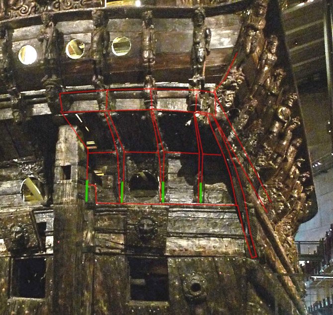
The arching planks towards the stern overhang looks a bit thick. I would probably remove these and just use the second layer planking. Remember, the decoration here goes on the outboard side of the planking without it being obvious from a distance that this is the case. This is what I did (sorry, not very sharp): Real ship: Cheers, Peter
.jpg.a46ca1cf2d3883bce93db266f819e6e6.jpg)
- 305 replies
-
- 6
-
-
- deagostini
- vasa
- (and 1 more)
-
Oh dear, I just ordered some stuff from a Swedish company, hope it doesn't get lost in the mail? :-/ The Vasa does not have a waterline as such, only loading marks, so I wouldn't worry.. ;-) /Peter
- 305 replies
-
- 3
-
-
- deagostini
- vasa
- (and 1 more)
-
If it helps, here are some views where you can see the run of the gun ports in the bow. https://digitaltmuseum.org/021016514730/regalskeppet-wasa-i-torrdocka-efter-bargningen-1961/media?aq=topic%3A"Regalskepp"&i=12 Note especially how forward facing the chaser ports are. As noted by Michael, you may need to more the upper gundeck port slightly upward. I suggest to keep an eye on your distance between the upper edge of the upper deck gunports and the height of the weatherdeck.. The hull shape is looking great. Looking forward to second planking.. Cheers, Peter
- 305 replies
-
- 5
-
-
- deagostini
- vasa
- (and 1 more)
-
The rigging is looking great. I'm not sure if I mentioned it earlier, but could make sense when researching rigging details; The Vasa was rigged by a scotsman. Looking at the bone model of Norske Løve in Rosenborg castle Copenhagen which was also rigged by a scotsman, you can spot some striking similarities. Regarding gun recoil; Indeed older guns would have been less powerful than later ones, both in terms of the effectiveness of the gunpowder, bit also in terms of metal strength of the barrel. As pointed out above, a longer gun barrel helps here, the reason for this is that the projectile accelerates for a longer time (acceleration ceases the moment the projectile leaves the barrel) These (weatherdeck)cannons have way less recoil than the main guns, they are also lighter and can be maneouvred easier, which could explain the need for less deckspace for these guns (-still, Corel has too little deckspace and oversize guns here. They also have bulkier deck gratings. On the Vasa, the deck grating is flush with the deck with only the coaming portruding) As to the point that the weatherdeck guns also could be loaded from the outside, it may be worth noting that the channels are located just below these guns. There is an interesting mix of new and old in the armament, even seen in the complement of 24 pounders; Gustav II Adolf drove a modernisation and standardisation of artillery in the army as well as the navy. A ship didn't have 'its own' guns in earlier days, it was equipped ad hoc with what was necessary and available, leading to a mix of all sorts of calibers that needed to be carried and also supplied to the right guns for battle. All 24 pounders were new and of standardized modern lighter style, except for two. It is interesting to compare these two variants: the old 24 pounders are about 37% longer and twice the weight of the new ones. Weatherdeck was armed with a mix of older cannons of weights nearly all the way down to 100kg. The weatherdeck represents the older armament style while the main gun decks represents new and modern. Lots of space here, including an unusual amount of headroom compared to other ships of the day, which in hindsight might not gave been such a good idea..
-
Problem with the lack of space for the guns is probably due to Corel errors in the hull shape. At least for the Corel Vasa, the deck is WAAY to narrow. I am not familiar with the La Couronne.. Unfortunately rather difficult to do anything about after the hull is built.. :-( -Peter
-
Hi Mr Pucko, A good idea. That is what I did too, -a word of caution though; You cannot just use the museum plans scaled to the correct scale as the template directly. The plan is a projection and therefore needs to be adjusted for the curvature of the hull. Cheers, Peter
- 305 replies
-
- 3
-
-
- deagostini
- vasa
- (and 1 more)
-
Looks good, With DeAgostini, you seem to be getting a pretty accurate model compared to other manufacturers. The hull shape looks excellent. There's always bound to be inaccuracies though, as long as they are accurate enough for your purposes, that's fine. (I't easy to get bogged down in correcting every detail) For the Corel Wasa, I found the inaccuracies too great to ignore with respect to the gun ports (wrong sizes, wrong locations, even the wrong number of gun ports), so I made a template from the museum plans. Even that is inaccurate, since I only made one template for both sides (on the real ship, the gun port layout differs from port to starboard) I would be a bit worried trusting the manufacturer to get all the building steps right though. (You mentioned it's difficult to change things when not knowing what DeAgostini has planned, do you get any plans from the start?) It often even pays to consider the rigging phase while building the hull. The Vasa for example has the main halliard knighthead below deck. It helps to rig this early in the build (before closing up the deck) I don't know what DeAgostini has planned here? Potentially place it on deck instead? Cheers, Peter
- 305 replies
-
- 5
-
-
- deagostini
- vasa
- (and 1 more)
-
-Also, the lower gun ports should be slightly larger than the upper. (That's despite the fact that both decks were armed with 24 pounders, -possibly an artefact from an earlier armament plan with smaller guns on upper gun deck) Looks good so far, just be careful of the structural integrity of the planking when you cut the gun ports if you still have gaps between the planks. cheers, Peter
- 305 replies
-
- 2
-
-
- deagostini
- vasa
- (and 1 more)
-
Hi Michael, I believe I heard from Fred Hocker that Vasa strangely enough had clove hitches on the last shrouds as well, so I would call it a win on the 1) -decision.. :-) Cheers, Peter
-
Hi Michael, It's looking really great! Amazing work! One question; I see you tried the main stay around the bowsprit, then decided against it? Which rigging plan are you rigging from? I believe the latest one hasn't been published yet (caught up in funding bureaucracy) Keep up the great work! Cheers, Peter
-
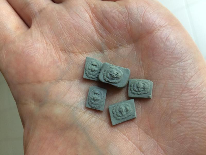
Sorry for the lack of updates, things have been a bit busy. Here's a current picture: sculpting gunport lions. The clay is Super Sculpey, oven bake polymer clay. Cheers, Peter
-
Found this: http://4.bp.blogspot.com/-2UZc9axeO0I/VdiCR6dPTEI/AAAAAAAAGxw/inrZpgmQd54/s1600/vasa12a.JPG This is the replica top at the museum, you can see the fid to the left. cheers, Peter
