Check out our new MSW Sponsor Innocraftsman
×

baskerbosse
-
Posts
212 -
Joined
-
Last visited
Content Type
Profiles
Forums
Gallery
Events
Everything posted by baskerbosse
-
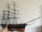
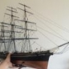 Sorry for the lack of updates, Not much going on here throughout July. I started making some blocks, using toothpicks. Needed to re-do the sheet rigging that was done using copper rings with a dab of glue on them. Needless to say, the rope does not run well through these blobs of glue which makes the re-rigging of these near impossible. New toothpick blocks (copper ring blob visible above): Other than that, fore yards now have blocks attached as well as footropes and halyard chains. Fore yards are hanging in their lowered position, will be hoisted when done. (easier to rig the lifts in this position) Cheers! /Peter
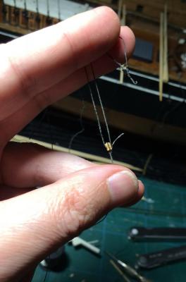

- 92 replies
-
- 7
-

-
- Cutty Sark
- Billing Boats
- (and 2 more)
-
Got drill chuck replacement, Much better (new one to the left). Spins perfectly true, even at Dremel speeds! :-) The right one, not so much.. Time for an attempt at miniature block making. Cheers! /Peter
-
Thanks Keith, Interesting, I hadn't noticed. I looked up some pictures, -for example: http://blogs.rmg.co.uk/cuttysark/wp-content/uploads/sites/13/2015/01/Cutty-Sark-at-Circular-Quay-discharging-cargo-in-Sydney-1890-%C2%A9-Cutty-Sark-Trust.jpg The Cutty Sark at Circular Quay. She also has fewer yards then unfortunately. Interesting how they take the bowsprit in when at port. (I've seen it on more than one picture of her at docks..) /Peter
-
Looks great! I love the detail of the construction, even where not visible! -Are you building at the Maritime Museum? Cheers, Peter
- 745 replies
-
- 1
-
-
- francis pritt
- mission ship
- (and 1 more)
-
Cutty Sark by NenadM
baskerbosse replied to NenadM's topic in - Build logs for subjects built 1851 - 1900
Hi Nenad, That is sad news indeed. Very sorry for your loss.. Take care, Peter- 4,152 replies
-
- 2
-
-
- cutty sark
- tehnodidakta
- (and 1 more)
-
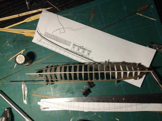
Received the drill chuck, which turned out to be a dud and more suited to draw circles with. The jaws were off center: https://goo.gl/photos/VvEPQvkaCTmJkbKj6 Credit to My Tool Store in Brisbane, responding straight away and sending a new one! (Will probably spend until well into next week in the care of Australia Post though.. :-) ) In the meantime, doing an experiment in small boat building: "Salslup #3" from FH af Chapman's Architectura, Plate 47: Scale? -Scaled to fit an A4 printout.. :-) Cheers, Peter
- 92 replies
-
- 1
-
-
- Cutty Sark
- Billing Boats
- (and 2 more)
-
Ok, well then. Warning was issued. Excuse the mess: Billings strange idea of anchor hoist: (windlass handles visible in the background) Fake 'blocks' I'm now getting rid of: Stunsail yards in progress (I know CS used to carry these, I might have been a bit unclear. What I meant to say was that lazy teenage me never made any, just parts of the attachment irons) Cheers, /Peter

- 92 replies
-
- 2
-
-
- Cutty Sark
- Billing Boats
- (and 2 more)
-
That looks nice! Haven't decided how to do my sheaves yet. Looks like some great ideas here! -cheers! /Peter
-
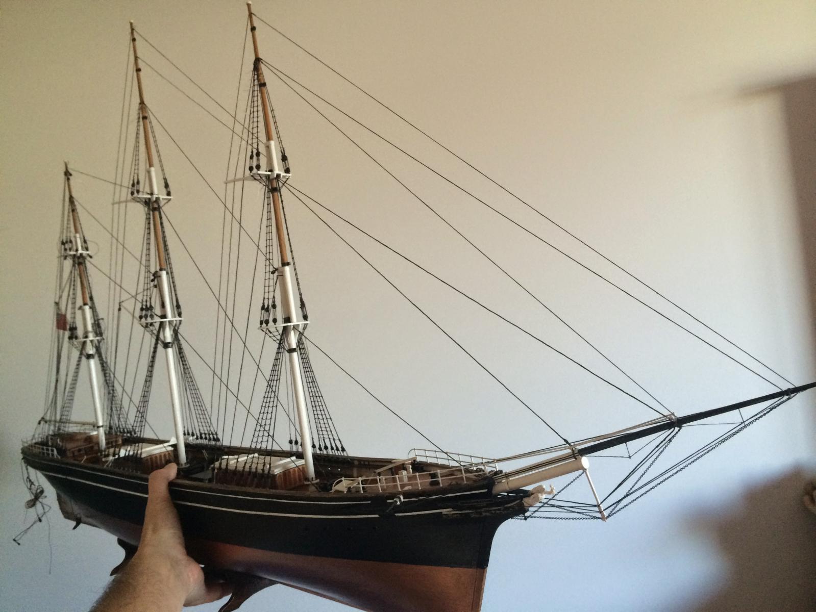
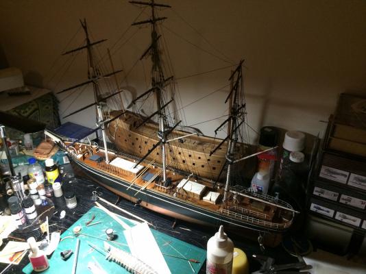
Update; Cleaned up the deck a bit. More paint touch up. Installed windlass handles. Started putting the yards up. No photos yet. Workspace needs serious cleanup.. I realised that the Billings CS does not have catheads. Instead some kind of deck crane for the anchor. Not fixing that one. In the meantime I have had some issues in that I had to fix. Number one, It would have appeared that I had the 'brilliant' idea when I built this model first, to simulate small blocks by using small copper rings that were then given a drop of glue to give it rounded appearance. Not very cooperative solution when you are re-rigging and need to tension lines up a bit. This was mostly on sheets and associated yard blocks. End result: had to cut most of it off. Now waiting for a drill chuck I ordered for my Dremel. Going to attempt making some small blocks, but my usual pin vise drilling is not something I'd like to try here... Number two, Work had been started on rigging stunsail yards, but no stunsail yards were ever made, nor provided in the kit. Made four so far, using bamboo skewers. (10 needed) She's starting to look alright now, with some yards up. Rather big too! :-) /Peter
- 92 replies
-
- 1
-
-
- Cutty Sark
- Billing Boats
- (and 2 more)
-
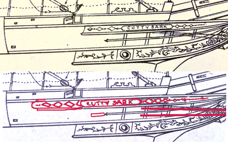
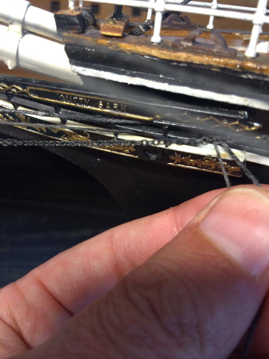
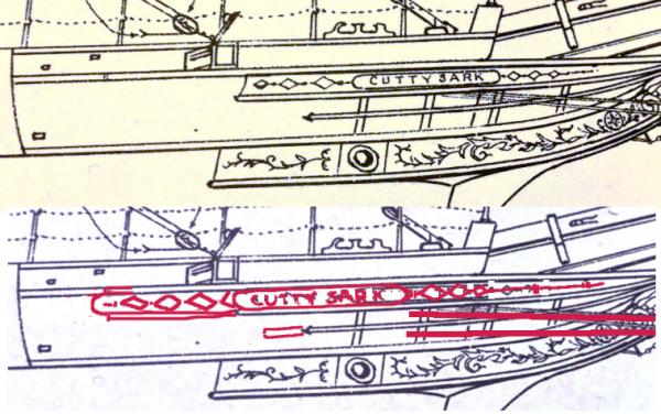
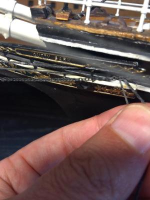
I just noticed that comparing this picture to the Billings name board. And then Campbell's name board, that the Campbell name board agrees with Billings. I.e. is also wrong. Something like this: Caution.
- 92 replies
-
- 1
-
-
- Cutty Sark
- Billing Boats
- (and 2 more)
-
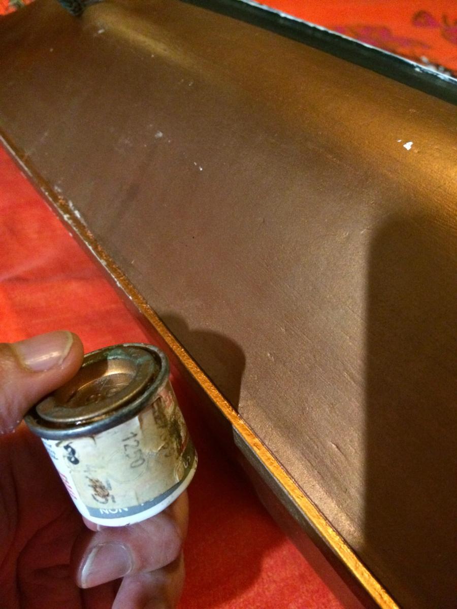
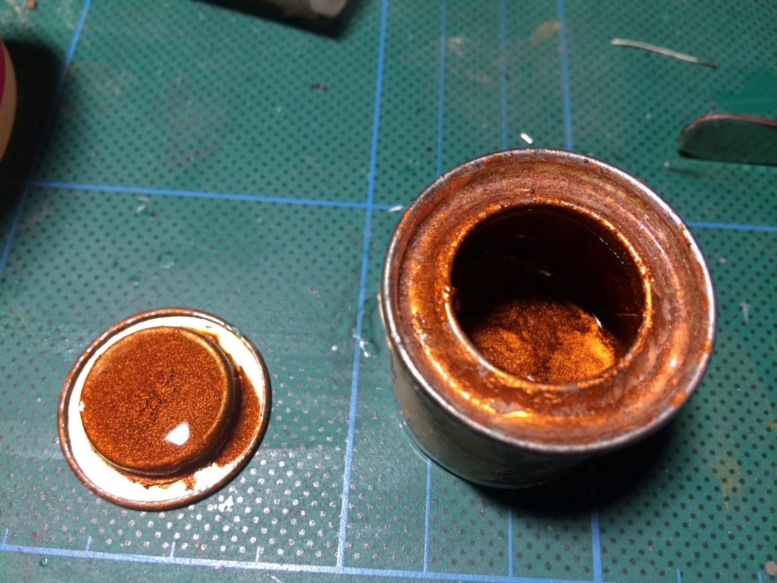
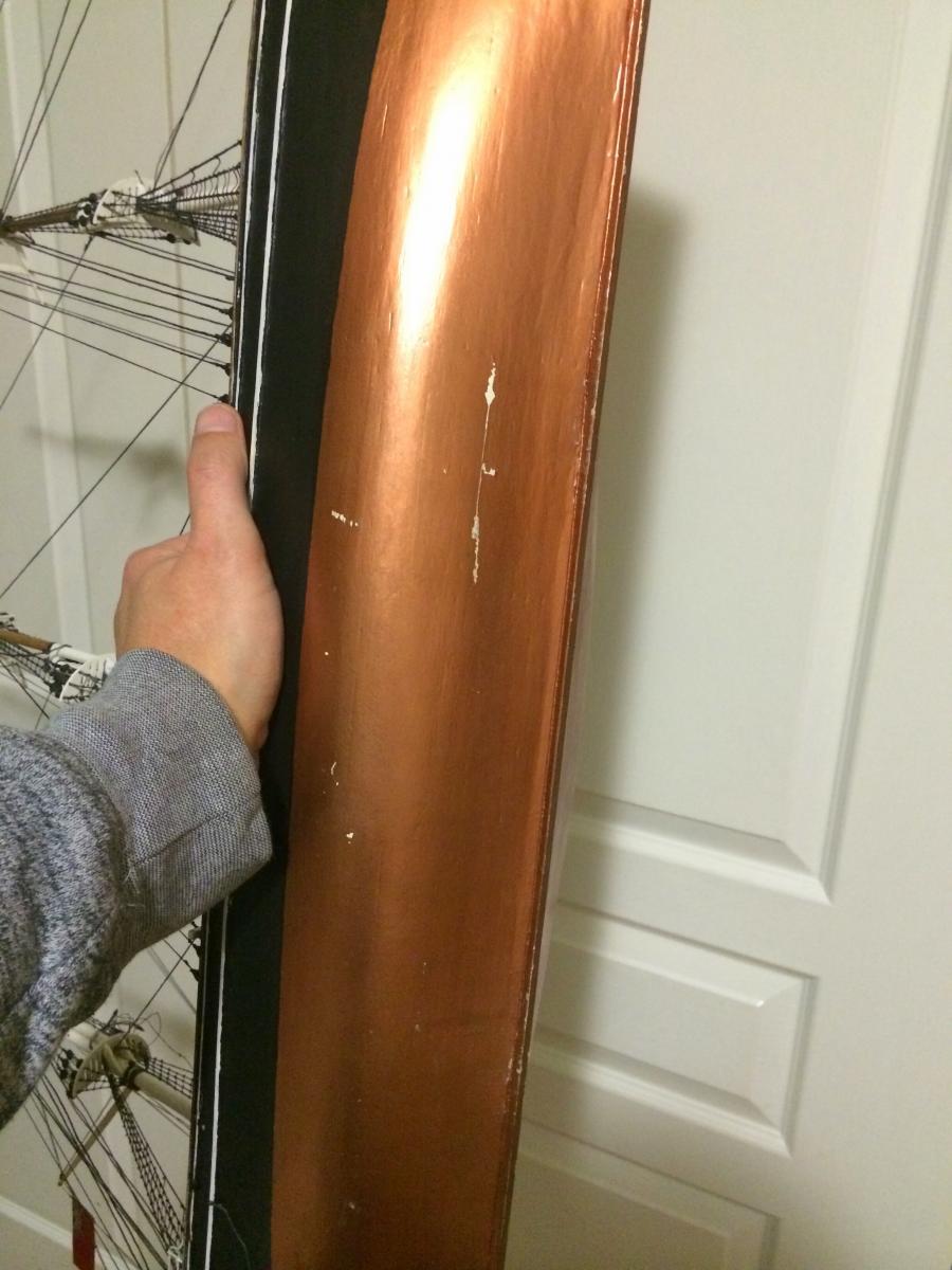
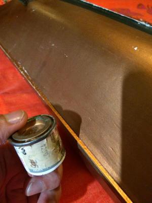
Wow, would you look at that. I think I found the original jar of paint I used.. ..And it's still usable!

- 92 replies
-
- 2
-
-
- Cutty Sark
- Billing Boats
- (and 2 more)
-
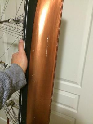
Thanks, I'll have a look. Perhaps if I can't find something exact, I can swap for the halyard chains. Unfortunately (again), when checking where on the hull the bowsprit shrouds attached, I noticed that the Billings name board is WAY too short! :-( It's supposed to go past the cathead.. -Nearly to the anchor hull padding.
-
Cutty Sark by NenadM
baskerbosse replied to NenadM's topic in - Build logs for subjects built 1851 - 1900
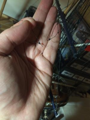
I tried using very thin copper wire from transformers, but I could not make it look right. Obviously a better material if you can make it work, since it comes in greater lengths and is easier to work with. However, if you pull at the copper version, it doesn't spring back. I used a hair because it had exactly the right springiness to form nice round loops. Didn't take long to make either (15 - 20 minutes). Problem would be to make longer stretches. It is also very elastic. It may not be suitable, I just mentioned it because I had good success in making a very small chain this way. Cheers, Peter- 4,152 replies
-
- 3
-
-
- cutty sark
- tehnodidakta
- (and 1 more)
-
Cutty Sark by NenadM
baskerbosse replied to NenadM's topic in - Build logs for subjects built 1851 - 1900
Hi Nenad, Sorry to hear about your family health, glad to hear your mother is feeling better. I did some simulated chain of small scale when I built my Wingnut Wings plastic WWI aircraft model. A chain was required from the cockpit to the wing radiator. I used a hair for that that I laid double and tied together in knots. Then I painted it silver. Ended up between 1/2 -> 1/3 mm thick Not sure if it's workable for the Cutty Sark, as there is quite a bit of this chain required and it's tedious work. http://1.bp.blogspot.com/-IMhu4g8y6tM/VLIDJaAx2PI/AAAAAAAAObg/GR5EgJuBx1Y/s1600/IMG_1187.JPG -The huge iron bar at the top is a .8 mm drill bit.. :-) http://3.bp.blogspot.com/-_4M2Ppatppw/VMbtkBy6hQI/AAAAAAAAOks/v0_oaS6Yk1w/s1600/IMG_1203.JPG (From http://wingnutbuild.blogspot.com.au/ ) /Peter- 4,152 replies
-
- 3
-
-
- cutty sark
- tehnodidakta
- (and 1 more)
-
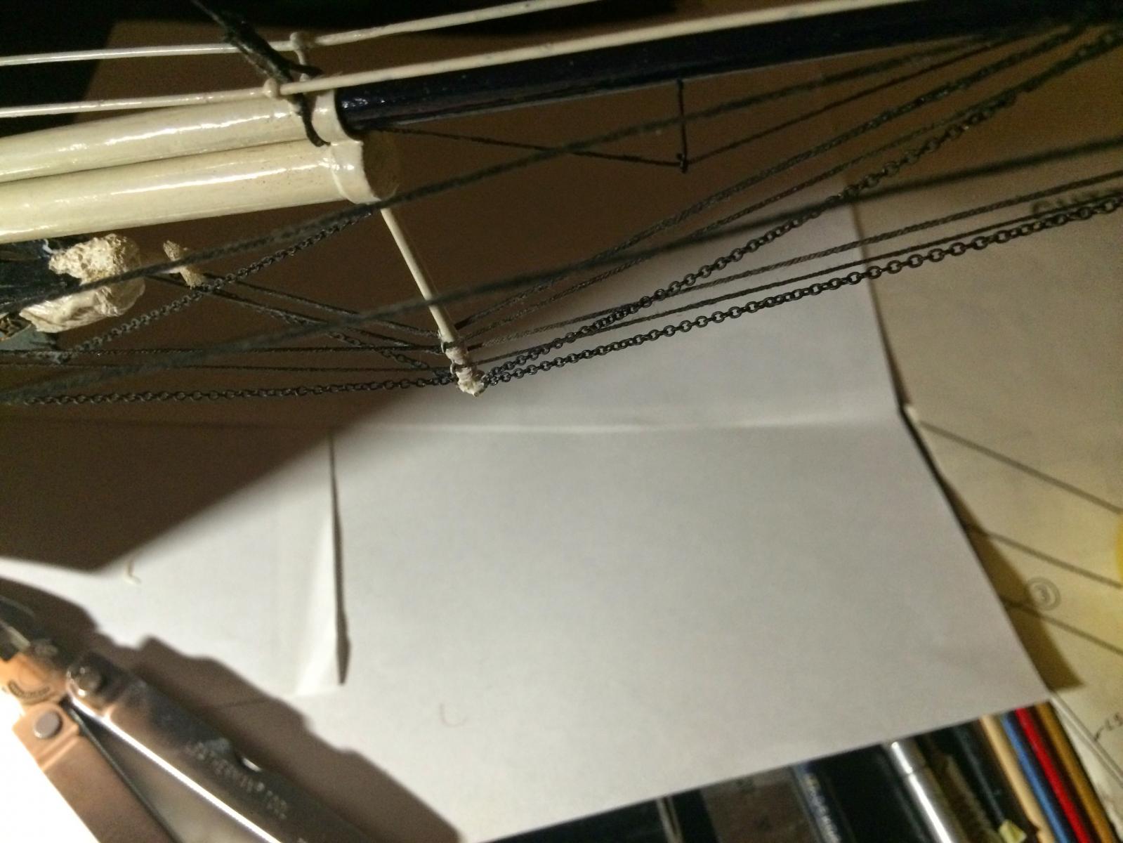
Oh oh, -Just noticed that the chain shrouds for the bowsprit are not rigged either and I don't think I have any more of the same chain.. :-(
-
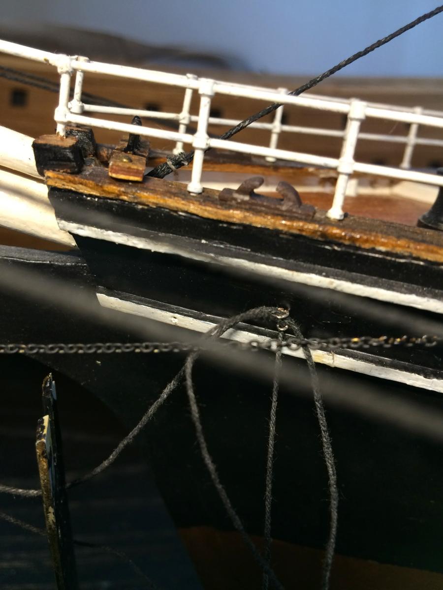
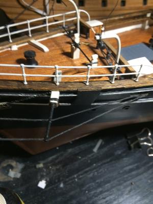
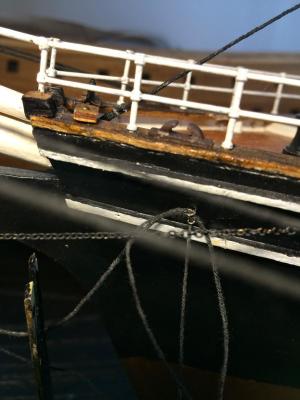
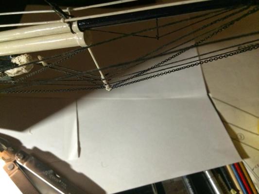
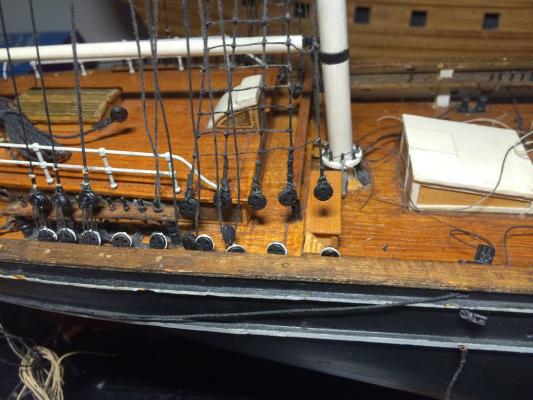
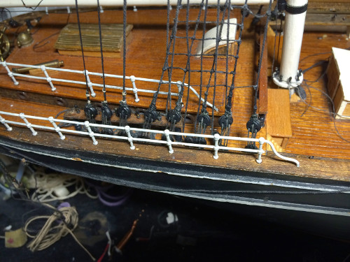
Time for an update; I have completed the rigging of the dolphin striker. A lot of lines were never rigged at all. Added attchment points: Run of lines: (sorry about the bad lighting) Standing rigging done: But the bottom could look better. Scuff marks and a crack: This needs to be fixed before the yards go on. /Peter

- 92 replies
-
- 3
-
-
- Cutty Sark
- Billing Boats
- (and 2 more)
-
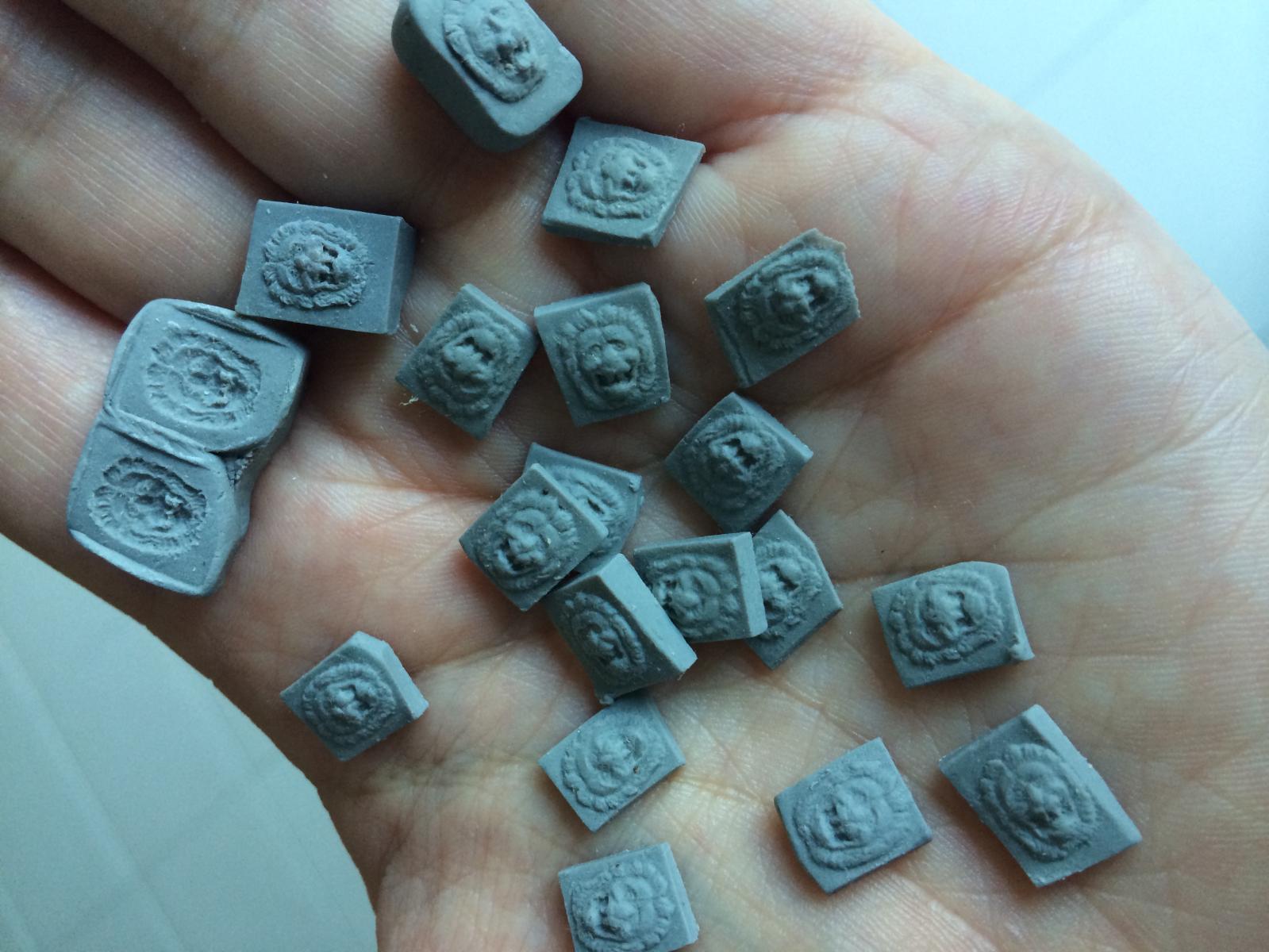
Hi Michael, I'm going to create a build log too. I was not in a hurry though, I do have another build log for rigging my old Cutty Sark model that I transported from Sweden to Australia (I took the masts down and took it as checked luggage! :-) ) This will probably take another couple of months, then I'll start working on my Vasa again. As for the sculptures, Intentions does not necessarily mean talent unfortunately. I'm going to cheat a bit. I have seen some really good wood carving on this site (and elsewhere), but I don't really feel confident doing that at this stage ( I did carve the Cutty Sark figurehead back when I was a teenager) Instead I'm doing some experiments with polymer clay (Super Sculpey): I made a master, and then a mould (inspired by the kid's Play Doh) -original is to the right of the mould. Then I can churn out multiple copies of a sculpture, adjust it as I like, and then bake it into a hard plastic. Cheers, /Peter

-
Hi Michael, You're doing real well with a difficult task! To me, it was all a bit disheartening (too much fixing of errors), but I'll be picking it up again soon! Well done to fit the extra gun port at the front. As you may have noticed, the problems with the Corel hull shape here are two; * The hull extends too far forward, over a centimetre too far * The hull is too narrow. This means the bow is not bluff enough, so the forward gunport ends up pointing in the wrong angle. If you look at your attached museum pictures (bottom one in post 905), you can see that the three most forward gunports all point somewhat forwards. It also means that in order for the beakhead to attach to the hull and still not need to be narrowed too much, the beahead sides will attach further aft, covering the place where the soldier sculpture should sit (as you noticed..) I reshaped the stern according to the museum plans as well. While the middle part was too narrow and required padding... ...the top was actually too wide. I will not be able to use many of the supplied figures, if any. The supplied top crest is now too wide to fit for example (proper stern outline to the left): The outline to right is not sloppily traced, this is the actual supplied Corel frame in my kit! Rather ridiculous shape.. :-( Cheers! /Peter
-
Yes, unfortunately Corel has the weather deck too short. To make it correct means extending it. The deck and hull are also considerably too narrow at the foremast. The foremast is also in the wrong place, it needs to move forwards, and the main mast needs to move aft. Unfortunately, they have made a bad job of the whole hull, which I don't understand why. When the lines exist for a ship, why all these differences? The hull is also too narrow and tall in general, as if they wanted to exaggerate a design fault. This is what I did: http://members.optusnet.com.au/~jenssen/index2.html
-
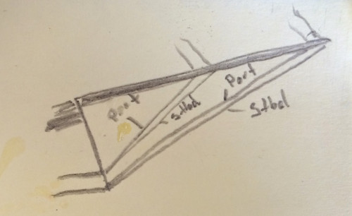
Yes, thanks Nenad. I think that does it. They are both wrong. The two outer stays go via the lower lead on the dolphin striker then to port and starboard. Then the two inner stays go to the upper lead on the dolphin striker, and the to port and starboard.
-
Found this one: http://justsaygo.com/wp-content/uploads/2013/11/CuttySbigger.jpg I think I'll go with my sketch in the end.. :-) thanks, Peter
-
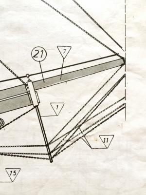
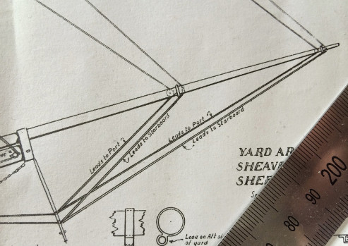
Hi Bob, (edit; -sorry, forgot the quote) " Allright; with all the forestays, (main, mizzen, etc.) their main principle is to keep the masts from falling backwards due to the tension on the backstays and shrouds, who in turn transmit the force of the wind into motion for the ship. The bowsprit will transfer some of these foremast static rigging forces, and dynamic running rigging forces, from the topmost forestays, down through the main forestays, through the bowsprit, and into the hull in a symmetrical manner. (divided by the dolphin striker.). " Yes, that is the general idea. I agree that Campbell's plans are excellent and essentially correct as far as I could find so far. However, please have a look exactly how he proposes to run the stays across the dolphin striker. The top position goes both to port, the bottom position goes both to starboard. Does not look right to me. Cheers, /Peter
-
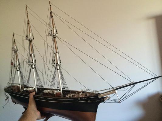
Rigging the bowsprit, particularly the dolphin striker. Again, Not confident about the Billings plan, since it has crossing ropes and the result is not optimal in a load bearing sense. Looked at the Campbell plans, but those do not make sense to me at all. (this has to be wrong..) Anyone had similar problems? I might just rig them as make sense to me: Two foremost ropes to the lower position on the dolphin striker and the other two on the upper position... Hard to tell in most pictures, but at least this one seems to favour my drawing? http://www.solarnavigator.net/history/explorers_history/Cutty_Sark_sailing_clipper_ship_Greenwich_October_2003.jpg Thoughts anyone?
- 92 replies
-
- 2
-
-
- Cutty Sark
- Billing Boats
- (and 2 more)
-
Got another half hour on the model last night (haven't had much time on it lately) Cut the lanyards, made and installed the extra deadeye. Second topmast backstay lying ready to be rigged on the deck in the background. Not quite happy with Billing's run of the halliards through the shrouds, but I'm going to leave that one alone:
- 92 replies
-
- 4
-
-
- Cutty Sark
- Billing Boats
- (and 2 more)
-
Well, This is what I had: A consequence of placing the deadeyes on the x-marks on Billing's deck plan: However, even Billing does not agree with this on their rigging plan, and places the foremost shroud parallel to the mizzen mast: Something that corresponds exactly with Campbell: (Also an interesting artefact: The two single blocks on the Campbell plan is there on the Billing plan too, except they have drawn no lines to them) Except that requires the foremost deadeye to be located here (arrow), which the Billing deck layout does not cater for..: ..-and fixed: Cheers, /Peter
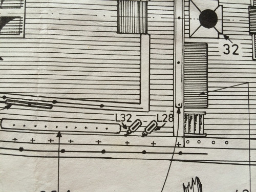

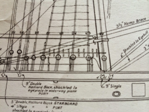
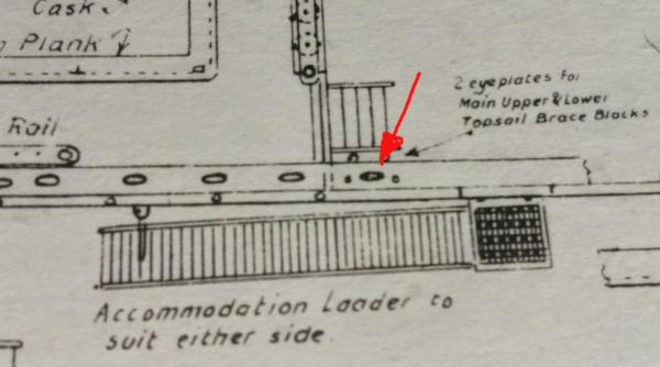
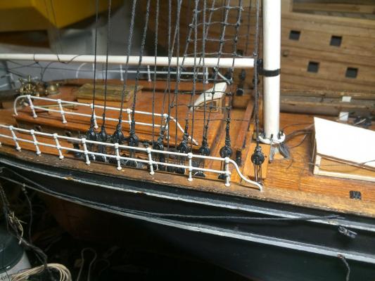
- 92 replies
-
- 4
-
-
- Cutty Sark
- Billing Boats
- (and 2 more)